

Page 1
Gen 2
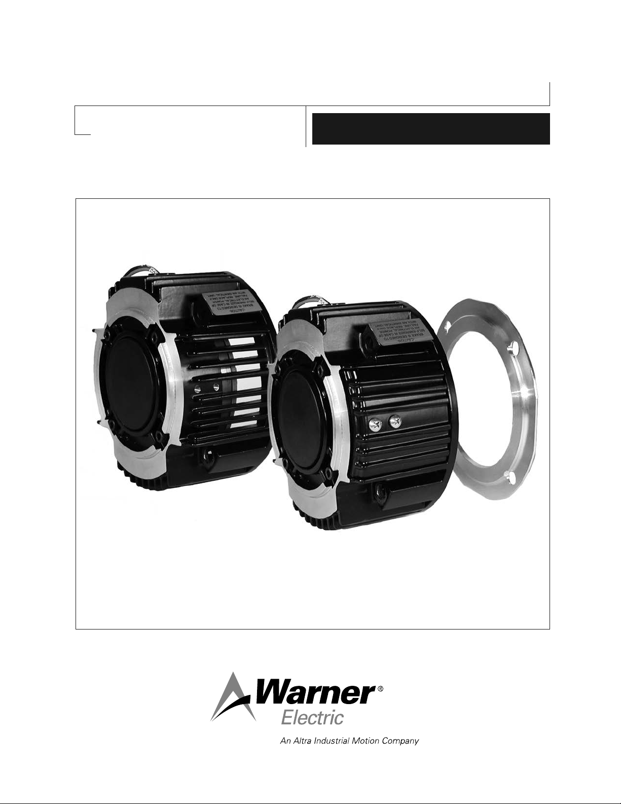
Electrically Released Motor Brake
Module for EM-MBFB and EUM-MBFB
P-273-8
819-0531
Installation Instructions
Vented
Enclosed Version Optional
Page 2
Warner Electric’s MBFB series of Electrically Released Brake Modules are designed for
brake only applications when mounted to the back of a NEMA C-face double shaft motor.
The fail safe brake engages when power goes off.
Mounting Instructions
Model Part No.
EM 50-20MBFB-10 5370-169-249
EM 50-20MBFB-10, 24V 5370-169-248
EM 100-20MBFB-21 5370-169-254
EM 100-20MBFB-21,24V 5370-169-253
EM 180-20MBFB-21 5370-169-259
EM 180-20MBFB-21, 24V 5370-169-258
EUM 50-20MBFB-6 5370-169-263
EUM 100-20MBFB-12 5370-169-264
EUM 180-20MBFB-12 5370-169-265
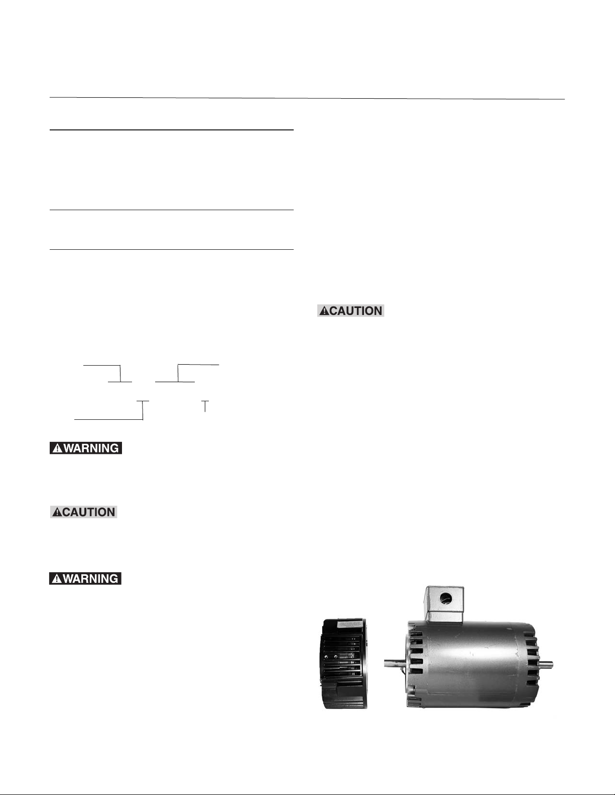
Step 1: Mounting the Brake to a Motor
The brake module (20MBFB) can be mounted
directly to the motor as follows:
A. Insert the key provided in the motor shaft
keyway. Prick punch the end of the motor
shaft keyway to prevent the key from sliding
out.
Note: The model EUM is a vented style
housing which includes the cover kit to
enclose the housing. The model EM
is a vented style housing. They can be
enclosed by purchasing the optional
cover kit 5370-101-082. (See page 4 for details.)
Model Configuration
EUM 50-20MBFB-6
Size Static Torque lb. ft.
Failure to follow these
instructions may result in product damage,
equipment damage, and serious or fatal injury
of personnel.
If brake is to be applied with the
brake output shaft in a vertical position
Warner Electric’s application engineering
should evaluate application.
B. Align the motor shaft and key with the mating
shaft hole and key slot in the brake module.
If anti-fretting lubricant is used
on the motor shaft for future ease of removal,
ensure that any excess is wiped off before
unit assembly to avoid lubricant
contaminating the clutch or brake friction
faces.
C. Slide the module onto the motor shaft so the
module surface is snug against the motor
face.
NOTE: Brake Module should slide freely
onto shaft and fit flush with motor C-face.
(Figure 1)
D. Secure the brake module (20MBFB) to the
motor C-face with the four (4) long hex head
capscrews provided. Tighten the four (4) bolts
alternately to ensure even alignment of the
module. Tighten them to 30-35 foot pounds.
The term “fail safe” describes a
brake that engages automatically when its full
power is shut off for whatever reason. The
term, as applied to brakes, designates a mode
of operation, not a guarantee of safety for the
equipment on which the brake is mounted and
for personnel who are near it.
Figure 1
Warner Electric • 800-825-9050 P-273-8 • 819-0531
2
Page 3

Step 2: Electrical Connections
24 Volt Brake recommended controls are:
The conduit hole in the motor brake is threaded
for standard pipe conduit connectors. The wiring
diagram included with each Warner Electric
control shows the proper electrical connections
to be made. Note: Controls used must have
adjustable output voltage.
Connect the red wire from the unit to the “+”
terminal of the DC supply and the black wire
from the unit to the “-” terminal of the DC supply.
Note: Refer to the brake release adjustment
procedure on page 4.
Control Requirements
All Permanent Magnet Type Electrically Released
Brake Modules are polarity sensitive. Therefore,
the red “+” wire must be connected to the “+”
terminal and the black “-” wire to the “-” terminal.
Potentiometer control will then provide
adjustment for the proper brake release point as
described in the “brake release” procedure on
page 4.
CBC-500-24, 24-30 VAC input
part no. 6024-448-002
CBC-550-24, 120/220/240/380/480 VAC input
part no. 6024-448-005
All Permanent Magnet type
Electrically Released Brake Modules are
polarity sensitive. See the service installation
sheet included with the control for connection
information
Burnishing and Maintenance
No burnishing required, units are pre-burnished
and armature airgap set at the factory.
As with any friction-type device, some initial
concern should be given to wear rate.
Improper voltage setting can reduce the braking
life. Once the best release voltage has been
established, precautions should be taken to
prevent machine operators, or other personnel
not familiar with wear characteristics, from
changing the potentiometer setting arbitrarily.
See the service installation instruction provided
with control for connection information.
90 Volt Brake recommended controls are:
*CBC-160-1 120 VAC input
part no. 6013-448-001
*CBC-160-2 220-240 VAC input
part no. 6013-448-002
CBC-200 120 VAC input
part no. 6011-448-001
CBC-300 120 VAC input
part no. 6021-448-001
CBC-500-90 120 VAC input
part no. 6024-448-003
CBC-550-90 120/220/240/380/480 VAC input
part no. 6024-448-006
*These controls are for use with conduit box kit
part no. 5370-101-042. All others require other
enclosures or alternate mounting.
Wear Pattern
Wear grooves appear on the friction surfaces.
This is a normal wear condition, and does not
impair functioning of the unit. Never machine the
friction surfaces to remove grooves or score
marks resulting from normal wear.
Foreign Materials
If units are used on machinery where ne,
abrasive dust, chips or grit are dispelled into the
atmosphere, or if the wear particles from the
brake are undesirable, you may use the optional
cover kit to enclose the module. See page 4 for
more information.
Where units are used near gear
boxes or transmissions requiring frequent
lubrication, means should be provided to
protect the friction surfaces from oil and
grease to prevent serious loss of torque.
Warner Electric • 800-825-9050 P-273-8 • 819-0531
3
Page 4

Brake Release Adjustment
Instructions for setting the optimum release
voltage of permanent magnet applied/electrically
released brakes.
The following procedure will
result in the brake releasing and allowing the
load to be free to move. Be sure the load is in
a safe condition before proceeding with this
process.
In a permanent magnet applied/electrically
released brake, the attractive force between the
brake surfaces is created by permanent
magnets. The brake is electrically released by
applying DC power to the electro-magnetic coil
in the brake that opposes the permanent
magnets.
Electrically released brakes are polarity sensitive:
The positive lead of the power supply must be
connected to the positive (red) lead of the brake
and the negative lead of the power supply must
be connected to the negative (black) lead of the
brake.
1. With power off, connect the positive lead
of the power supply to the positive (red) lead
of the brake and the negative lead of the
power supply to the negative lead (black) of
the brake.
2. Connect a volt-meter to measure the voltage
applied across the brake.
3. Adjust the power supply to its lowest possible
output, and then energize the power supply to
apply power to the brake.
4. Starting from the low voltage point, slowly
increase the applied voltage while visually
watching the brake armature through the vents
on either side of the module and through the
½ by 1 inch window in the clutch rotor fan until
the brake armature disengages from the brake
magnet. Note and record this voltage reading.
5. Add twenty (20) volts for a 90 volt brake and
ve (5) volts for a 24 volt brake to this reading
and set the supply to this level. This will be the
proper release voltage for your setup.
The power supply applied to the brake must also
be adjustable so that the optimum release
voltage for each individual brake can be
determined and set.
The following procedure describes how to set the
adjustable power supply to the optimum release
point of the brake. A volt-meter is required to
perform the procedure.
No power is applied to motor during this
procedure. Power normally supplied by motor
to brake control should be supplied by
alternate method.
6. With the brake energized, spin the motor shaft
by hand to insure that it turns freely. If a
scraping sound is noted when the output shaft
is spun, it means an armature is dragging
slightly. Correct this problem by repeating
steps 1 through 5 above.
If any problems should occur during adjustments
or application questions arise, please contact
Technical Support at 1-800-825-9050 Monday
through Friday 7:30 a.m. - 4:30 p.m. central time.
Warner Electric • 800-825-9050 P-273-8 • 819-0531
4
Page 5
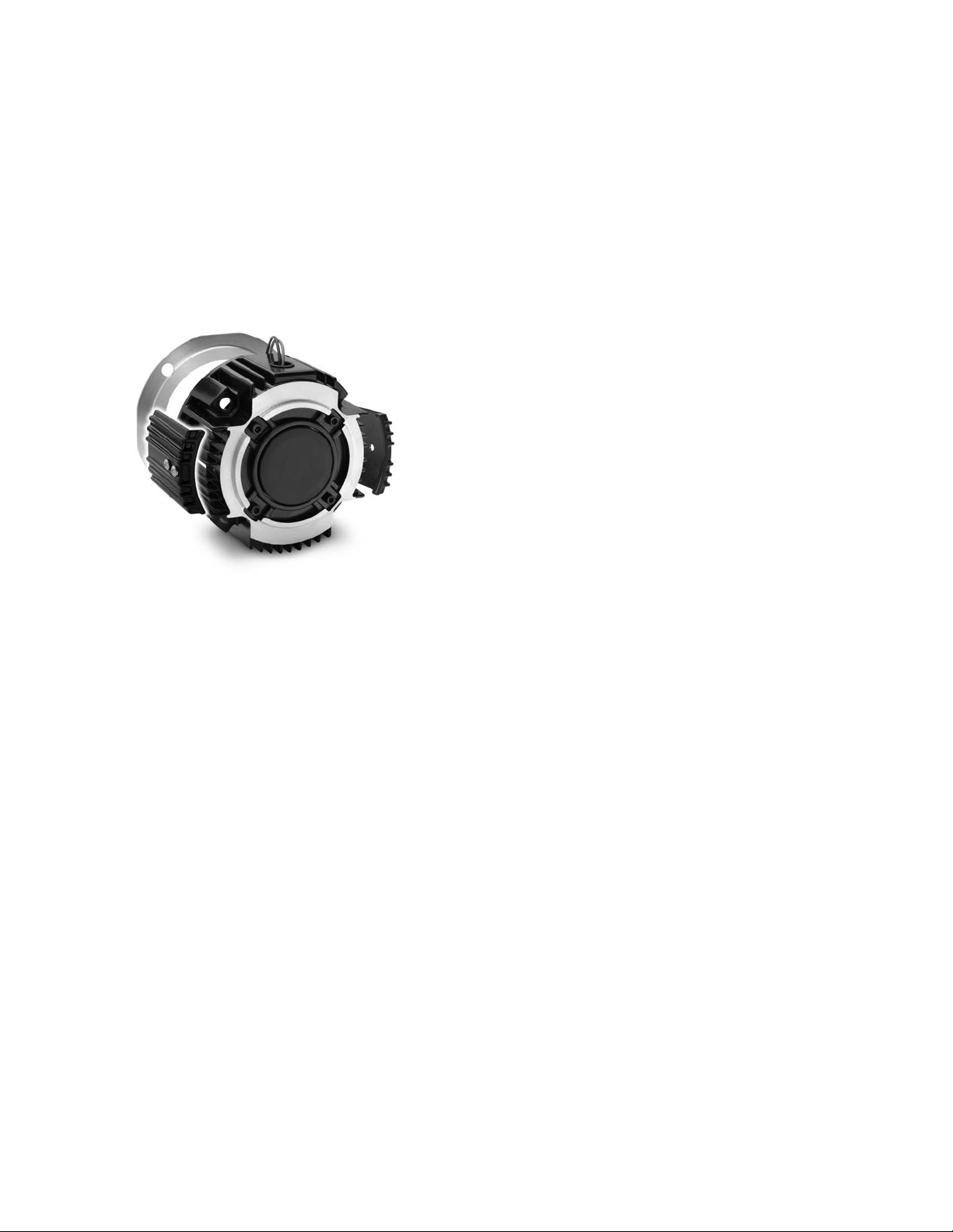
Enclosed EM-20MBFB Module Option
If an Enclosed Brake-Module is required, an
optional Cover Kit, Warner Electric part number
5370-101-082, can be purchased separately to
enclose the open vents in the housing and a
cover plate to close off the back of the Module.
Each Cover Kit includes two (2) vent covers, four
(4) screws and one (1) cover plate needed to
convert a vented EM-20MBFB to an enclosed
design (non-washdown) as shown in Figure 2.
Figure 2
Note: When using this cover kit to enclose the
module the vent covers should be assembled as
the nal step.
Notes:
Visit Warner Electric’s website at
www.warnerelectric.com for dimensional drawings, weights, inertias, and a complete offering of
our products including clutches, brakes and
clutch/brake controls and service parts.
In addition, Warner Electric module products,
controls, and service parts information can be
found in our Packaged Electromagnetic
Clutches/Brakes Catalog P-1234-WE. Call
815-389-3771 to request any of our catalogs.
Warner Electric • 800-825-9050 P-273-8 • 819-0531
5
Page 6

Warranty
Warner Electric LLC warrants that it will repair or replace (whichever it deems advisable) any
product manufactured and sold by it which proves to be defective in material or workmanship within a
period of one (1) year from the date of original purchase for consumer, commercial or industrial use.
This warranty extends only to the original purchaser and is not transferable or assignable without Warner
Electric LLC’s prior consent.
Warranty service can be obtained in the U.S.A. by returning any defective product, transportation charges
prepaid, to the appropriate Warner Electric LLC factory. Additional warranty information may be obtained
by writing the Customer Satisfaction Department, Warner Electric LLC, 449 Gardner Street, South Beloit,
Illinois 61080, or by calling 815-389-3771.
A purchase receipt or other proof of original purchase will be required before warranty service is
rendered. If found defective under the terms of this warranty, repair or replacement will be made, without
charge, together with a refund for transportation costs. If found not to be defective, you will be notified and,
with your consent, the item will be repaired or replaced and returned to you at your expense.
This warranty covers normal use and does not cover damage or defect which results from
alteration, accident, neglect, or improper installation, operation, or maintenance.
Some states do not allow limitation on how long an implied warranty lasts, so the above limitation may not
apply to you.
Warner Electric LLC’s obligation under this warranty is limited to the repair or replacement of the
defective product and in no event shall Warner Electric LLC be liable for consequential, indirect,
or incidental damages of any kind incurred by reason of the manufacture, sale or use of any defective
product. Warner Electric LLC neither assumes nor authorizes any other person to give any other warranty
or to assume any other obligation or liability on its behalf.
WITH RESPECT TO CONSUMER USE OF THE PRODUCT, ANY IMPLIED WARRANTIES WHICH THE
CONSUMER MAY HAVE ARE LIMITED IN DURATION TO ONE YEAR FROM THE DATE OF ORIGINAL
CONSUMER PURCHASE. WITH RESPECT TO COMMERCIAL AND INDUSTRIAL USES OF THE
PRODUCT, THE FOREGOING WARRANTY IS IN LIEU OF AND EXCLUDES ALL OTHER WARRANTIES,
WHETHER EXPRESSED OR IMPLIED BY OPERATION OF LAW OR OTHERWISE, INCLUDING, BUT NOT
LIMITED TO, ANY IMPLIED WARRANTIES OF MERCHANTABILITY OR FITNESS.
Some states do not allow the exclusion or limitation of incidental or consequential damages, so the above
limitation or exclusion may not apply to you. This warranty gives you specific legal rights and you may also
have other rights which vary from state to state.
Changes in Dimensions and Specifications
All dimensions and specifications shown in Warner Electric catalogs are subject to change without notice.
Weights do not include weight of boxing for shipment. Certified prints will be furnished without charge on
request to Warner Electric.
Warner Electric LLC
31 Industrial Park Road • New Hartford, CT 06057
815-389-3771 • Fax: 815-389-2582
www.warnerelectric.com
P-273-8 • 819-0531 6/12 Printed in USA
 Loading...