

Page 1

EnclosedUniModuleInstallationandTechnical
ProceduresRegularandWashdownModels
EUM-50/EUM-100/EUM-180/EUM-210/EUM-215
P-226
819-0355
Installation & Operating Instructions
Page 2

Contents
Introduction
Pre-Installation Instructions . . . . . . . . . . . . . . . . 2
Installation Instructions . . . . . . . . . . . . . . . . . . . 3
Electrical Coil Data, Mechanical Data . . . . . . . . 7
Overhung Load Data. . . . . . . . . . . . . . . . . . . . . 7
Pre-Burnishing & Maintenance . . . . . . . . . . . . . 8
Troubleshooting . . . . . . . . . . . . . . . . . . . . . . . . 9
Dimensions EUM-1020 . . . . . . . . . . . . . . . . . . 10
Dimensions EUM-2030 . . . . . . . . . . . . . . . . . . 11
EUM Parts List/1020 Combinations . . . . . . . . 12
EUM Parts List/2030 Combinations . . . . . . . . 14
Warranty. . . . . . . . . . . . . . . . . . . . . . Back Cover
Failuretofollowthese
instructionsmayresultinproduct
damage,equipmentdamage,and
seriousorfatalinjurytopersonnel.
This manual covers installation, wiring and
troubleshooting of regular and washdown models
of Enclosed UniModule clutch/brake sizes 50,
100, 180, 210, and 215. Washdown models are
designed to be liquid tight under normal
washdown conditions and the special instructions
required to install these products follow with the
instructions for the regular units. Mechanical and
electrical specifications and dimension drawings
are included.
Makesureallpoweristurned
offtothisequipmentwheninstalling,as
injury(orevendeath)mayresultfromcontact
withlivewiresorrotatingshafts.
Pre-InstallationInstructions
A. The Enclosed UniModule has been designed to
NEMA standards and can be installed with all
standard power transmission drive
systems.
B. Before installing the Enclosed UniModule to a
motor or reducer, make certain that the EUM
size and NEMA frame dimensions match
according to the chart on the right.
C. Check the motor for shaft endplay. If the shaft
can be moved axially .030" or more, the
module should not be installed since excessive
thrust may occur between the rotor and field.
The motor should not be used unless the
endplay can be reduced.
Corresponding
NEMAFrameSize C-Face
EUM Old New Shaft Pilot
Size NEMA NEMA Dia. Dia.
50 56 C 48 Y 5/8" 4-1/2"
100 56 C 48 Y 5/8" 4-1/2"
180 182 C 143 TC 7/8" 4-1/2"
184 C 145 TC
210 213 C 182 TC 1-1/8" 8-1/2"
215 C 184 TC
215 213 TC 1-3/8" 8-1/2"
215 TC
Warner Electric • 800-825-9050 P-226 • 819-0355
2
Page 3

FortheseEUMcombinations: Usetheseinstallationsteps:
Enclosed UniModule Clutch-Brake Between
C-Face Motor and Reducer – 1020 1, 2, 3, 4, 7
Enclosed UniModule Clutch-Brake – 2030 4, 7
Motor Mount Enclosed UniModule Clutch-Brake
On C-Face Motor – 1020-M 1, 2, 3, 6, 7
Base-Mounted
Enclosed UniModule Clutch-Brake – 2030-B 5, 7
InstallationInstructions
Warner Electric’s Enclosed UniModule has been
designed to NEMA standards and can be
installed with all standard power transmission
drive systems. Before installing the Enclosed
UniModule to a motor or reducer, make certain
that the EUM size and NEMA frame dimensions
match according to the chart.
Install your specific modular combination
according to the installation steps specified in
the table on page 2. Use only those steps
indicated for each combination.
Note:The equipment covered by this service
manual must be installed in accordance with
these instructions. Failure to do so may
damage the equipment and void the warranty.
Note: Special plugs and plastic screws are
provided with each washdown kit. All unused
holes are to be plugged to prevent debris
buildup and to ensure that the clutch/brake
stays dry.
MountingToAMotor
Step1:
A. For Washdown Models Only:
1. Slip rubber shield (seal) over clutch and end
of module; exact position of rubber band is
described in step 3.B. Place gasket
between motor and clutch end; be sure to
select correct gasket to match clutch end.
Warner Electric • 800-825-9050 P-226 • 819-0355
3
Page 4

B. For All UniModule Models
Note: The 1020 UniModule is furnished with
a special key already assembled in the rotor
hub. Do not use another key!
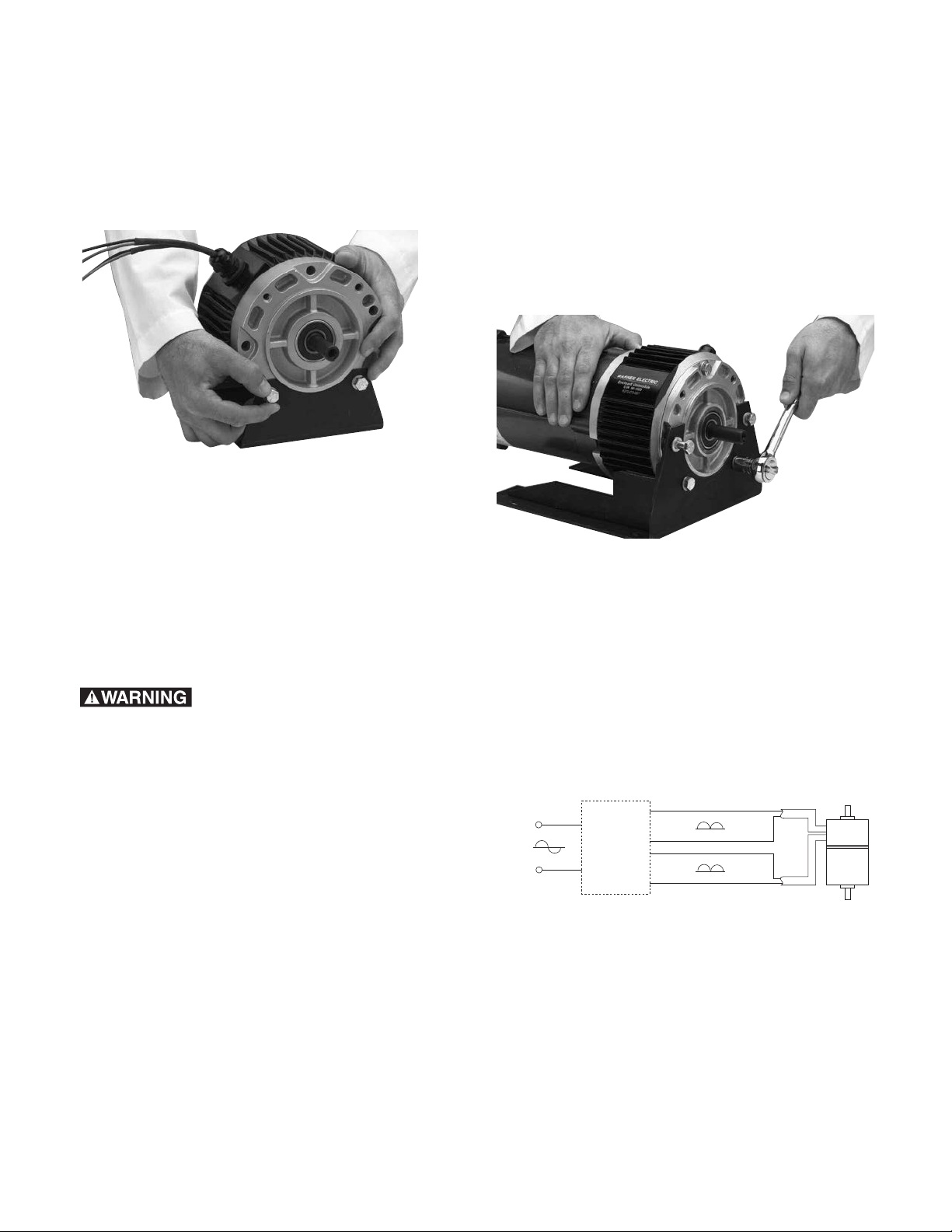
1. Before sliding UniModule onto motor, align
set screws on rotor input hub to access
slots on clutch side of module. Insert into a
set screw and slide assembly onto motor
shaft as shown in Figure 2. Align key in
UniModule with motor shaft keyway.
tapped holes on motor face. Tighten
alternately and securely to 30 to 35 ft. lbs.
torque. See Figure 3.
Figure 3
Step3:
A. For All UniModule Models
1. Tighten both set screws on the module
input hub with prepositioned Allen wrench
alternately and securely to 80 to 85 in. lbs.
for all sizes. See Figure 4.
Figure 2
Do not use force. If UniModule does not
slide on freely, polish motor shaft sufficiently
to achieve a slip fit.
Note: Sizes 100, 210 and 215 UniModules
require an adapter ring to be mounted to
the motor prior to mounting the 1020
UniModule. Adapter and mounting
hardware are provided with the
UniModule assembly.
Step2:
A. For UniModule Models Other Than
Washdown
1. Insert four large capscrews with lock
washers provided through mounting holes in
housing and into tapped holes on motor
face. Tighten alternately and securely to 30
to 35 ft. lbs. torque. See Figure 3.
B. For Washdown Models Only
1. Insert four large capscrews provided
through the large plastic washers and
through mounting holes in housing and into
Figure 4
B. For Washdown Models Only
1. After tightening set screws on the rotor
input hub, Figure 3, use plastic screws
provided in the kit to plug threaded holes
and position rubber seal to cover all slots.
Step4: Mounting to a Reducer
The output side of a UniModule may be mounted
directly to a reducer.
Warner Electric • 800-825-9050 P-226 • 819-0355
4
Page 5

A. For Washdown Models Only
1. Place a gasket between reducer and
clutch/brake; select correct gasket to match
brake end configuration. See Figure 5.
Figure 5
B. For All UniModule Models
1. Align output shaft and key of UniModule
with corresponding shaft hole and keyway
of reducer. Slide assembly together,
matching pilot diameter on UniModule with
a pilot diameter on reducer. See Figure 6.
Step5:Installing the Base Mount on 2030
UniModules
A. For All UniModule Models
1. Mount each UniModule so that base is
located below ventilation holes. A pilot
diameter on end of each UniModule mates
with pilot diameters on base. See Figure 7.
2. Secure base to UniModule with the bolts
provided. Tighten to 18 to 22 ft. lbs. torque
for 50 and 180 sizes, 40 to 45 ft. lbs. torque
for 210 and 215 sizes.
Figure 7
Step6: Installing the Motor Mount (M)
Motor Mount (M) can be installed to output end of
UniModule to provide a foot mounting for
complete assembly of UniModule and motor.
A. For All UniModule Models
Sizes 50, 100 and 180
1. Remove the four set screws plugging the
mounting holes. Remove the two long hex
head bolts from side of UniModule toward
ventilation holes.
2. Mount UniModule on Motor Mount so base
of Motor Mount is underneath UniModule
and motor. See Figure 8. A pilot diameter on
Figure 6
UniModule mates with a pilot diameter on
Motor Mount.
2. Bolt UniModule to reducer flange. The four
bolts required (3/8-16 UNC-2A) are normally
furnished with the reducer. Tighten to 18 to
22 ft. lbs. torque for 50 and 180 size, 40 to
45 ft. lbs. torque for 210 and 215 sizes.
3. Secure Motor Mount in place with two
longer mounting bolts. Tighten to 30 to 35
ft. lbs. torque and two shorter bolts tighten
18 to 22 ft. lbs. torque, all provided in kit.
Sizes 210 and 215
1. Mount UniModule on Motor Mount so base
of Motor Mount is underneath UniModule
Warner Electric • 800-825-9050 P-226 • 819-0355
5
Page 6
and motor. See Figure 8. A pilot diameter on
Clutch/Brake
Control
AC
Clutch
Brake
White
Black
Red
Red
Black
Black
DC
DC
Voltage
Voltage
Voltage
UniModule mates with a pilot diameter on
Motor Mount.
2. Secure Motor Mount to the UniModule with
three bolts provided and tighten to 40 to 45
ft. lbs. torque.
Figure 8
B. For Washdown Models Only
1. If any mounting bolts are not used, make
sure the mounting holes are plugged with
the .437 diameter plugs provided. For 210
and 215 size units, make sure holes on
circumference are plugged with the .375
plugs provided.
Step7: Electrical Connections
Toavoidinjury(orevendeath)
alwaysmakecertainallpowerisoffbefore
attemptingtoinstallorservicethiscontrolor
anyelectricalequipment.
Electric control show the proper electrical
connections.
Please refer to Figure 9 for the proper
UniModule electrical connections. Clutch
andbrakeleadsareidentifiedwith
labels.
B. For Washdown Model Only
1. Use only liquid tight connectors with flexible
tubing for connections.
Figure 9
After wiring, your Enclosed UniModule is now
ready to operate. If your clutch/brake control has
torque control, the torque adjust potentiometer(s)
should be set for rapid and complete load take
up. Excessive slippage of the brake or clutch can
cause overheating and premature wear. For
additional information, including the armature
adjustment which is occasionally required for
new installations, see page 7 of this manual.
A. For All UniModule Models
1. The UniModule is provided with one conduit
connection hole, threaded for standard 1/2"
conduit connectors. Both the clutch and
brake lead wires are brought out through
this opening. The conduit box accessory kit,
P/N 5370-101-042 for non-washdown
models, and 5370-101-045 for washdown
models, provides two conduit connection
holes for standard 1/2" conduit connectors.
The clutch and brake coils operate on DC
voltage. Warner Electric offers a full line of
AC voltage powered controls to meet the
needs of almost every clutch/brake
application. The service and installation
instructions included with each Warner
Warner Electric • 800-825-9050 P-226 • 819-0355
6
Page 7

ElectricalCoilData
MechanicalData
Clutch Brake Clutch Brake Clutch Brake
Voltage–D.C. 90 90 24 24 66
Resistance EUM-50 452 452 31.8 31.8 1.86 1.86
(OHMS) EUM-100 362 362 26.7 26.7 1.9 1.9
EUM-180 362 362 26.7 26.7 1.9 1.9
EUM-210 264 264 17.9 17.9 1.33 1.33
EUM-215 264 264 17.9 17.9 1.33 1.33
Amperes EUM-50 .199 .201 .755 .755 3.23 3.23
EUM-100 .249 .249 .896 .896 3.1 3.1
EUM-180 .249 .249 .896 .896 3.1 3.1
EUM-210 .341 .341 1.34 1.34 4.5 4.5
EUM-215 .341 .341 1.34 1.34 4.5 4.5
WATTS EUM-50 18 18 18 18 19 19
EUM-100 22 22 21.5 21.5 19 19
EUM-180 22 22 21.5 21.5 19 19
EUM-210 30.7 30.7 32 32 27 27
EUM-215 30.7 30.7 32 32 27 27
Build Up EUM-50 52 53 52 53 52 53
(Milli- EUM-100 72 75 72 75 72 70
seconds) EUM-180 72 75 72 75 72 70
EUM-210 120 100 120 100 110 100
EUM-215 120 100 120 100 110 100
Decay EUM-50 6.2 5.0 6.2 5.0 6.5 5.0
(Milli- EUM-100 12 10 12 10 12 10
seconds) EUM-180 12 10 12 10 12 10
EUM-210 20 10 20 10 20 10
EUM-215 20 10 20 10 20 10
Static Torque 16 lb. ft. 16 lb. ft. 30 lb. ft. 95 lb. ft. 95 lb. ft.
EUM-50 EUM-100 EUM-180 EUM-210 EUM-215
Maximum Speed 3600 rpm 3600 rpm 3600 rpm 3600 rpm 3600 rpm
Average Wt.-lbs.
Motor Clutch 3.4 lbs. 5.1 lbs. 5.1 lbs. 9.1 lbs. 9.1 lbs.
Brake 6.6 8.1 8.1 21.5 21.5
Input Clutch 6.4 8.4 8.4 19.8 19.8
Output Clutch 4.9 5.2 5.2 15.2 15.2
Inertia – WR
Armature .007 .018 .018 .081 .081
lb. ft. lb. ft. lb. ft. lb. ft. lb. ft.
Armature hub .002 .003 .003 .021 .021
Shaft .001 .002 .002 .017 .017
Rotor w/Fan
and hub .020 .046 .046 .188 .188
OverhungLoadData
Overhung load data is provided in this manual for
the design engineer concerned with specific
requirements in this area. The maximum allowable
overhung load which can be applied to the shaft
of a UniModule may be determined by the use of
the accompanying chart.
DistanceLoadisApplied Maximum
fromHousingFace LoadRating
ModuleSize “A”Inches “R”lbs.
EM-50 1'' – Center of Shaft 177
EUM-50 2'' – End of Shaft 123
3'' 95
EM-100 1'' – Center of Shaft 177
EUM-100 2'' – End of Shaft 123
3'' 95
EM-180 1'' – Center of Shaft 192
EUM-180 2'' – End of Shaft 134
3'' 104
EM-210 1-3/8'' – Center of Shaft 386
EUM-210 2-3/4'' – End of Shaft 271
4-1/8'' 208
EM-215 1-3/8'' – Center of Shaft 386
EUM-215 2-3/4'' – End of Shaft 271
4-1/8'' 208
Based on 10,000 Hour Life at 3600 RPM.
The minimum pitch diameter pulley or sprocket that
can be used, for satisfactory bearing life, is
determined from the formula:
Min. P.D. = 2 T K
R
T – Torque (in. lbs.). This is the torque actually being
transmitted, not necessarily the maximum torque
capacity of the Electro-Module.
Torque = 63025 x HP
RPM
K – The safety factor for the tension in the type of
drive.
Use: 1 chain and sprocket
1 for timing belt
2 for V-belt
3 for flat belt
R – Radial load allowable (values at various distance
from the housing face are given in the chart).
Example: What is the minimum V-belt pulley that
can be applied to the center of the shaft of an EM50 module. The torque requirement is 112. in. lbs.
Min. P.D. = 2 x 112 x 2
= 2'' minimum P.D. pulley
224
Warner Electric • 800-825-9050 P-226 • 819-0355
7
Page 8

Pre-BurnishingandMaintenance
Pre-Burnishing
All Warner Electric UniModules are pre-burnished
before leaving the factory and are designed to pull
full torque as shipped. Like all friction based
products, their consistency will improve after a
short break-in period.
Maintenance
As with any friction-type device, some initial care
should be given to wear rate, as minor
adjustments in actuation time can sometimes
extend the life of the unit.
The exploded views and drawing illustrate and
describe the various components in each
Electro-Module.
Wear Pattern
Wear grooves appear on the friction surfaces.
This is a normal wear condition, and does not
impair functioning of the unit. Never machine the
friction surfaces to remove grooves or score
marks resulting from normal wear.
Torque Loss
If a brake or clutch module slips or loses torque
completely, the initial check should be the input
voltage to the magnet or field as follows:
90-Volt: Connect a DC voltmeter with a range of
0-100 volt directly across the magnet or field
terminals. With the power on and the
potentiometer turned up, a normal reading is 90
volts, although 85 to 95 is satisfactory. The
reading should drop as the potentiometer
control is adjusted counterclockwise.
6-Volt: Use a DC voltmeter of approximately 0-15
volt range. A normal reading is from 5.5 to 6.5
volts, depending on the power supply.
The above checks normally are sufficient. Further
checks may be made as follows: a low range
ammeter, when connected in series with one
magnet lead, will normally indicate 0.2 to .35
amperes for the 90 volt units and 3.0 to 4.5 for
the 6 volt series. These readings are with the
power on and the potentiometer control in the
maximum position.
Heat
Excessive heat and high operating temperatures
are causes of rapid wear. Units, therefore, should
be ventilated as efficiently as possible, especially if
the application requires fast, repetitive cycle
operation.
Foreign Materials
Do not spray internal friction surfaces with oil.
EUMs will withstand humid, wet environments.
The washdown version is able to withstand high
pressure wash applications.
Ohmmeter checks should be made with the
power off and the circuit open. (To be certain,
disconnect one lead to the magnet.) Compare
resistance to the data on page 8.
If the above checks indicate that the proper
voltage and current is being supplied to the coil,
mechanical parts should be checked to assure
that they are in good operating condition and
properly installed.
Warner Electric • 800-825-9050 P-226 • 819-0355
8
Page 9

Troubleshooting
With the motor at rest and locked out, check the
following:
A. Spin the output shaft by hand to ensure that it
turns freely.
B. If the unit fails to engage, first check the power
supply. Then remove the four screws of the
access panel on the side of the unit. With full
voltage applied to the clutch or brake, switch
back and forth between the clutch and brake
and observe the armatures (plates) through the
access hole. They should move back and forth
approximately 1/32'' when switched.
C. If a scraping sound is noted when the output
shaft is spun, it means an armature is dragging
slightly because of shock and displacement
during shipment. This is easily corrected.
Figure 10
Remove the four screws of the access panel
on the side of the unit. Insert a screwdriver
through the access hole and pry the dragging
armature (clutch or brake as observed) away
from the mating surface evenly all the way
around as far as it will move. Then apply power
to the magnet and insert the screwdriver
between the two armatures (back to back) to
nudge them evenly back into complete
contact. Pry only on the outer edge of the
armature to avoid damaging the autogap
assembly. This will reset the autogap in the
proper position and the unit should now be
ready for further assembly in the drive system
and normal operation. See Figure 10.
Replace the access panel on the assembly.
Warner Electric • 800-825-9050 P-226 • 819-0355
9
Page 10
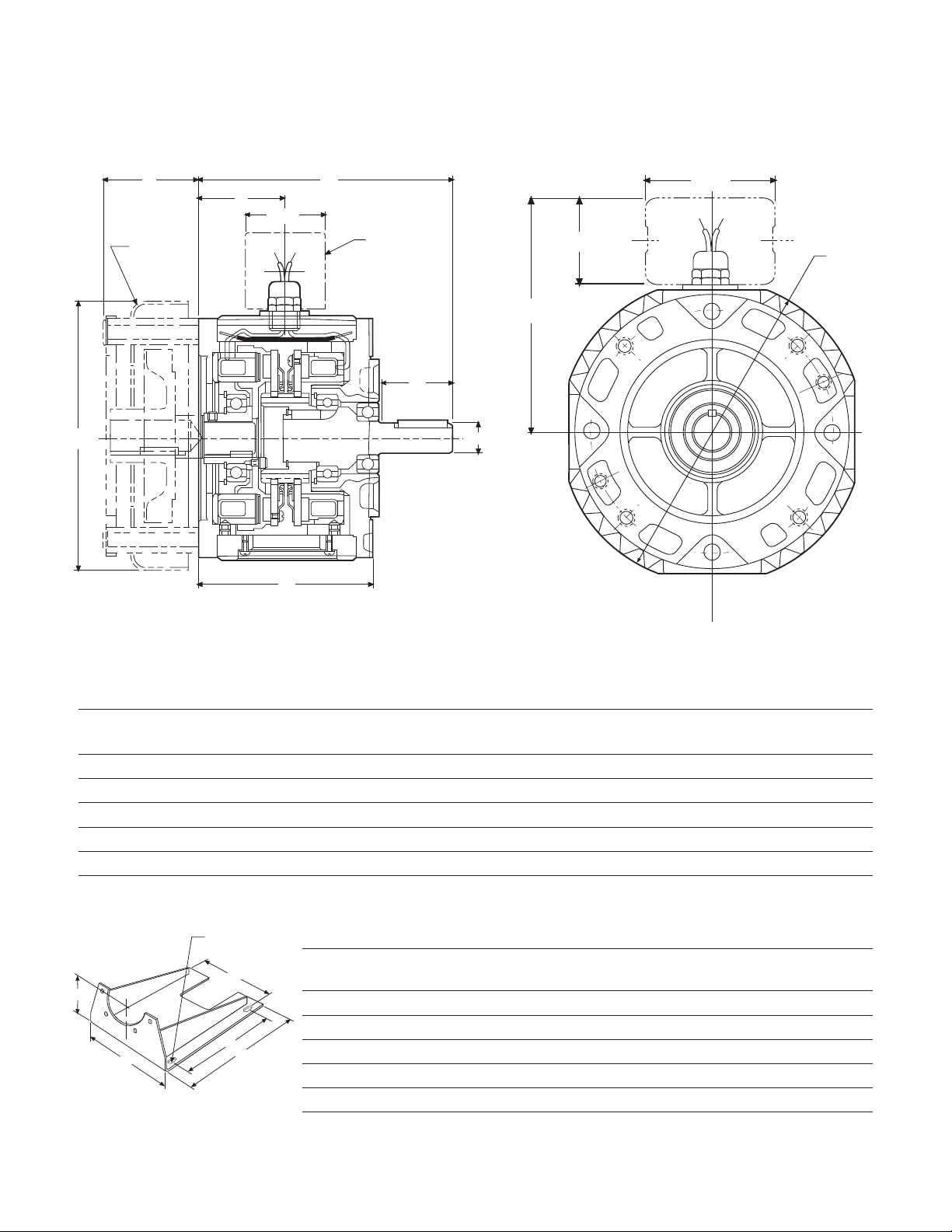
EnclosedUniModuleCombinations
E
3.125
2.188
G
C
min.
D
B
20
Brake
10
Motor
Clutch
H
Optional
Fan Kit
I
F
A
2.203
Optional
Conduit Box
E
F (4) slots
B
D
C
A
DimensionsEUM-1020
Note:Washdown Unimodules (EUM-W) do not have a finned housing.
EUM1020 Motor mounted UniModules
E
Size AB CDEUM EUM-W FGHI
50 6.750 4.844 1.813 .625 7.270 6.915 2.427 5.936 7.687 2.430
100 6.750 4.844 1.890 .625 7.270 6.915 2.427 5.936 7.687 2.430
180 6.828 4.844 1.890 .875 7.270 6.915 2.427 5.936 7.687 2.430
210 8.891 5.922 2.500 1.125 10.000 10.00 3.053 7.146 10.187 3.375
215 8.891 5.922 2.500 1.375 10.000 10.00 3.053 7.146 10.187 3.375
MotorMount(M)
Size ABCDE F EUM EUM-W
50 9.250 8.250 11.000 8.000 3.500 .796 x .406 5370-101-010 5370-101-048
100 9.250 8.250 11.000 8.000 3.500 .796 x .406 5370-101-010 5370-101-048
180 9.250 8.250 11.000 8.000 4.500 .796 x .406 5370-101-012 5370-101-049
210 11.500 10.500 12.000 9.000 5.250 .750 x .406 5371-101-012 5371-101-026
215 11.500 10.500 12.000 9.000 5.250 .750 x .406 5371-101-012 5371-101-026
PartNo.
Warner Electric • 800-825-9050 P-226 • 819-0355
10
Page 11

EnclosedUniModuleCombinations
C
min.
D
30
Input
Clutch
B
Optional
Base Mount
D
C
min.
Optional
Conduit Box
A
F
2.203
3.125
2.188
E
G
H
Optional
Base Mount
E
F (4) slots
A
D
C
B
DimensionsEUM-2030
Note: Washdown UniModules (EUM-W) do not have a finned housing.
EUM2030 Base mounted UniModules
Size AB CDEUM EUM-W FGHI
50 9.516 5.719 1.813 .625 7.270 6.915 3.164 5.936 3.670 7.119
180 9.516 5.719 1.890 .875 7.270 6.915 3.164 5.936 4.484 8.119
210 12.969 7.719 2.500 1.125 10.000 10.00 4.514 7.146 5.234 10.234
E
Base(B)
Size AB C D E F EUM EUM-W
50 6.000 5.000 5.672 4.000 2.171 .750 x .406 5370-101-062 5370-101-046
100 6.000 5.000 5.672 4.000 2.171 .750 x .406 5370-101-062 5370-101-046
180 6.625 5.000 5.672 4.000 3.000 .750 x .406 5370-101-002 5370-101-047
Warner Electric • 800-825-9050 P-226 • 819-0355
210 9.000 7.750 8.203 6.000 3.375 .750 x .531 5371-101-001 5371-101-025
215 9.000 7.750 8.203 6.000 3.385 .750 x .531 5371-101-001 5371-101-025
PartNo.
11
Page 12

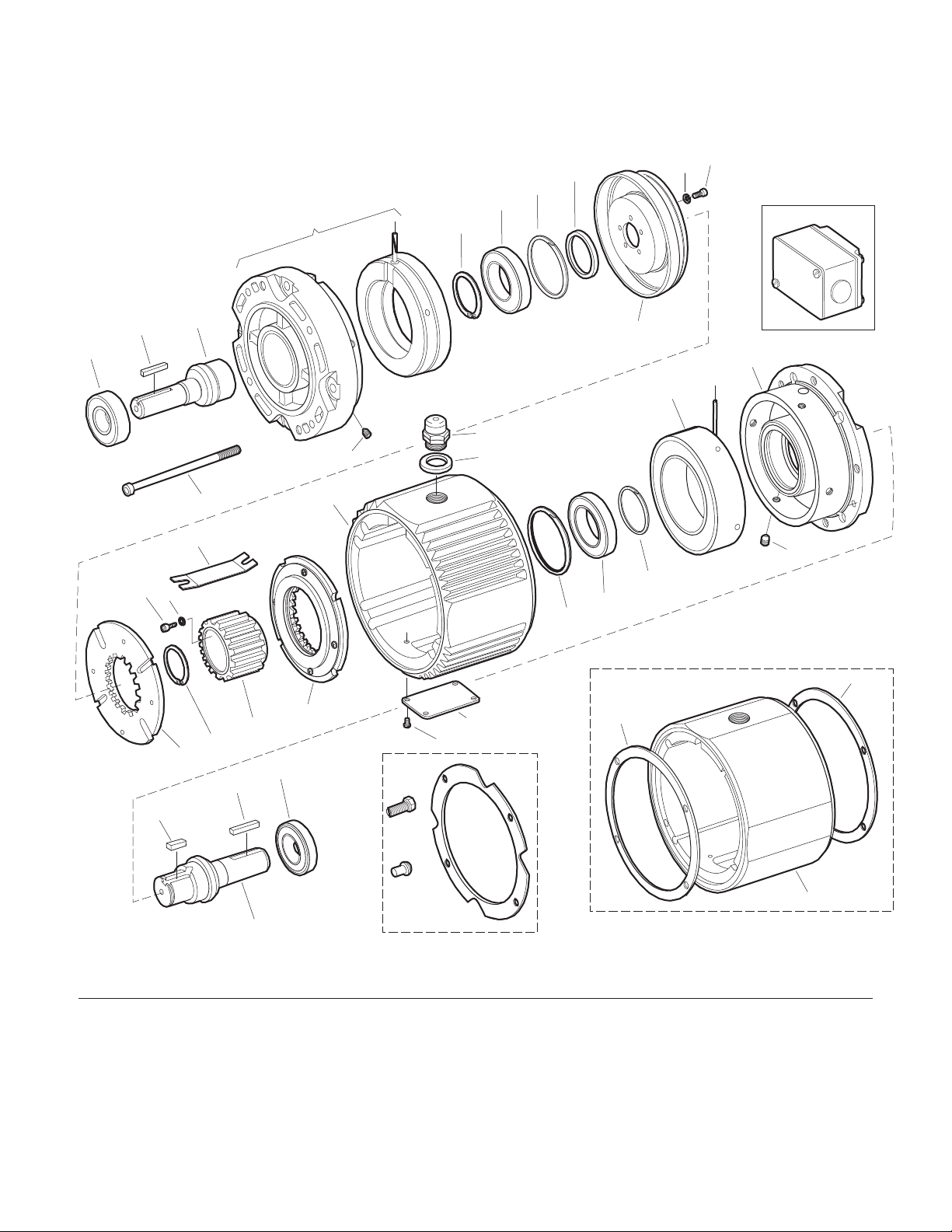
EnclosedUniModulePartsList
10
19
9a
17
17a
18
11a
11
Optional
21
21W
5
4
23
1
3
2
1
14
20
20W
22
6a
13a
13
7a
6b
7b
16a
16
16W
2a
Optional
12
12W
9a
8
9
26W
26W
14W
Optional
15
15W
1020Combinations
Specifications EUM-50 EUM-100 EUM-180 EUM-210 EUM-215
Voltage – DC 6, 24 or 90 6, 24 or 90 6, 24 or 90 6, 24 or 90 6, 24 or 90
Static Torque – lb.ft. 16 30 30 95 95
Maximum Speed – RPM 3600 3600 3600 3600 3600
Average Weight – lbs. 10.0 13.2 13.2 30.6 30.6
Total cycled inertia
– WR2(lb.ft.2) .017 .041 .041 .20 .202
Warner Electric • 800-825-9050 P-226 • 819-0355
12
Page 13

UniModuleAssemblies
PartNumbers Washdown
Unit Enclosed(EUM) EUM-W)
Size Voltage UniModule UniModule
50-1020 6V 5370-273-058 5370-273-100
24V 5370-273-059 5370-273-101
90V 5370-273-057 5370-273-099
100-1020 6V 5370-273-092 5370-273-108
24V 5370-273-093 5370-273-109
90V 5370-273-091 5370-273-107
Unit Enclosed(EUM) (EUM-W)
Size Voltage UniModule UniModule
210-1020 6V 5371-273-028 5371-273-056
24V 5371-273-029 5371-273-057
90V 5371-273-027 5371-273-055
215-1020 6V 5371-273-048 5371-273-064
24V 5371-273-049 5371-273-065
90V 5371-273-047 5371-273-063
PartNumbers Washdown
180-1020 6V 5370-273-066 5370-273-116
24V 5370-273-067 5370-273-117
90V 5370-273-065 5370-273-115
ComponentParts
Item Description EUM-50 EUM-100 EUM-180 EUM-210 EUM-215
1 Armature Assembly 5370-111-011 (2) 5370-111-013 (2) 5370-111-013 (2) 5371-111-005 (2) 5371-111-005 (2)
2 Armature Hub 540-1638 540-1642 540-1642 540-0741 540-0741
2a Key 590-0043 590-0084 590-0084
3 Retaining Ring 748-0445 748-0676 748-0676
4 Lockwasher 950-0121 (6) 950-0121 (6)
5 Capscrew 797-0081 (6) 797-0081 (6)
6a Retaining Ring 748-0113 (2) 748-0101 748-0101 748-0112 748-0112
6b Retaining Ring 748-2002 748-2002
7a Ball Bearing 166-0149 166-0101 166-0101 166-0142 166-1042
7b Ball Bearing 166-0155 166-0143 166-0143 166-0144 166-0144
8 Endbell/Brake 456-1014 456-1019 456-1019 456-1017 456-1017
9 Brake Magnet
6 Volt 5370-631-037 5370-631-002 5370-631-002 5371-631-002 5371-631-002
24 Volt 5370-631-038 5370-631-005 5370-631-005 5371-631-005 5371-631-005
90 Volt 5370-631-036 5370-631-003 5370-631-003 5371-631-003 5371-631-003
9a Set Screws 797-0471 (4) 797-1386 (4) 797-1386 (4) 797-0103 (4) 797-0103 (4)
10 Clutch Field/End Bell Assembly
6 Volt 5370-451-077 5370-451-086 5370-451-086 5371-451-033 5371-451-044
24 Volt 5370-451-078 5370-451-087 5370-451-087 5371-451-034 5371-451-045
90 Volt 5370-451-076 5370-451-085 5370-451-085 5371-451-032 5371-451-046
11 Rotor/Hub Assembly 5370-751-023 5370-751-035 5370-751-024 5371-751-014 5371-751-028
11a Set Screws 797-1098 (2) 797-1249 (2) 797-1249 (2) 797-1098 (2) 797-1098 (2)
12 Mounting Accessory Kit 5370-101-040 5370-101-040 5370-101-040 5371-101-040 5371-101-024
13 Cover Plate 686-1055 686-1055 686-1055 686-1055 686-1055
13a Cover Plate Screws 797-0575 (4) 797-0575 (4) 797-0575 (4) 797-0575 (4) 797-0575 (4)
14 Center Housing 535-0176 535-0176 535-0176 535-0177 535-0177
15 Conduit Box 5370-101-042 5370-101-042 5370-101-042 5370-101-042 5370-101-042
16 Shaft 798-0046 798-0128 798-0085 798-0051 798-0255
16a Key 590-0029 590-0029 590-0029 590-0019 590-0124
17 Retaining Ring 748-0101 (2) 748-0101 748-0101 748-0558 748-0558
17a Ball Bearing 166-0150 166-0300 166-0300 166-0168 166-0168
18 Retaining Ring 748-0018 748-0018 748-0018 748-0067 748-0067
19 Assembly Bolts 797-1433 (2) 797-1433 (2) 797-1433 (2) 797-1438 (2) 797-1438 (2)
20 Connector 280-0038 280-0038 280-0038 280-0038 280-0038
21 Accessory Fan 5370-101-055 5370-101-055 5370-101-054 5371-101-029 5371-101-034
22 Washer 950-0441 950-0441 950-0441 950-0441 950-0441
23 Insulator 572-0327 572-0327 572-0327 572-0327 572-0327
EUM-WUniqueParts
12W Washdown Mounting Kit 5370-101-052 5370-101-052 5370-101-052 5371-101-041 5371-101-028
14W Center Housing for Washdown 535-0181 535-0181 535-0181 535-0182 535-0182
15W Conduit Box Kit 5370-101-045 5370-101-045 5370-101-045 5370-101-045 5370-101-045
16W Shaft 798-0263 798-0265 798-0262 798-0259 798-0267
20W Conduit Connector 280-0058 280-0058 280-0058 280-0058 280-0058
21W Fan Kit 5370-101-060 5370-101-060 5370-101-061 5371-101-033
26W Gasket/Seal Repair Kit 5370-101-058 5370-101-058 5370-101-058 5371-101-032 5371-101-032
Warner Electric • 800-825-9050 P-226 • 819-0355
13
Page 14
EnclosedUniModulePartsList
22
16a
12
12W
9a
10
19
18
21
17
23
11b
11a
11
Optional
15
15W
9a
8
9
6b
7
6a
20
20W
25
14
13a
13
1
26
2
3
1
5
4
2a
16a
24
16
16W
(2)
req'd.
(6)
req'd.
(8)
req'd.
27W
28W
28W
14W
2030Combinations
Specifications EUM-50 EUM-180 EUM-210
Voltage – DC 6, 24 or 90 6, 24 or 90 6, 24 or 90
Static Torque – lb.ft. 16 30 95
Maximum Speed – RPM 3600 3600 3600
Average Weight – lbs. 13 16.5 41.3
Total cycled inertia
– WR
2
(lb.ft.2) .017 .041 .20
Warner Electric • 800-825-9050 P-226 • 819-0355
14
Page 15

UniModuleAssemblies
Partnumbers
Unit Enclosed(EUM) Washdown(EUM-W)
Size Voltage UniModule UniModule
50-2030 6V 5370-273-062 5370-273-104
24V 5370-273-063 5370-273-105
90V 5370-273-061 5370-273-103
180-2030 6V 5370-273-070 5370-273-120
24V 5370-273-071 5370-273-121
90V 5370-273-069 5370-273-119
210-2030 6V 5371-273-032 5371-273-060
24V 5371-273-033 5371-273-061
90V 5371-273-031 5371-273-059
ComponentParts
Item Description EUM-50 EUM-180 EUM-210
1 Armature Assembly 5370-111-011 (2) 5370-111-013 (2) 5371-111-005 (2)
2 Armature Hub 540-1638 540-1642 540-0741
2a Key 590-0043 590-0084
3 Retaining Ring 748-0445 748-0676
4 Lockwasher 950-0121 (6)
5 Capscrew 797-0081 (6)
6a Retaining Ring 748-0113 748-0101 748-0112
6b Retaining Ring 748-2002
7 Ball Bearing 166-0149 166-0101 166-0142
8 Endbell/Brake 456-1014 456-1019 456-1017
9 Brake Magnet
9a Set Screws
10 Clutch Field/End Bell Assembly
11 Rotor 5370-751-033 5370-751-034 5371-751-006
11a Screw 797-1294 (4) 797-1214 (5) 797-0081 (6)
11b Washer 950-0102 (4) 950-0102 (5) 950-0121 (6)
12 Shaft/Clutch 798-0047 798-0124 798-0123
13 Cover Plate 686-1055 686-1055 686-1055
13a Screws 797-0575 (4) 797-0575 (4) 797-0575 (4)
14 Center Housing 535-0176 535-0176 535-0177
15 Conduit Box 5370-101-042 5370-101-042 5370-101-042
16 Shaft/Brake 798-0046 798-0085 798-0051
16a Key 590-0029 (2) 590-0029 (2) 590-0019 (2)
17 Retaining Ring 748-0113 (2) 748-0101 748-0112
18 Retaining Ring 748-0017 748-0202
19 Assembly Bolts 797-1477 (2) 797-1477 (2) 797-1476 (2)
20 Connector 280-0038 280-0038 280-0038
21 Bearing 166-0149 166-0101 166-0142
22 Bearing 166-0155 166-0143 166-0144
23 Spacer 807-0062 807-0061
24 Bearing 166-0155 166-0143 166-0144
25 Washer 950-0441 950-0441 950-0441
26 Insulator 572-0327 572-0327 572-0327
EUM-WUniqueParts
12W Shaft/Clutch 798-0264 798-0261 798-0260
14W Center Housing for Washdown 535-0181 535-0181 535-0182
15W Conduit Box Kit 5370-101-045 5370-101-045 5370-101-045
16W Shaft/Brake 798-0263 798-0262 798-0259
20W Conduit Connector 280-0058 258-0058 258-0058
27W Washdown Mounting Kit 5370-101-051 5370-101-051 5371-101-027
28W Gasket/Seal Repair Kit 5370-101-058 5370-101-058 5371-101-032
6 Volt 5370-631-037 5370-631-002 5371-631-002
24 Volt 5370-631-038 5370-631-005 5371-631-005
90 Volt 5370-631-036 5370-631-003 5371-631-003
6 Volt 5370-451-082 5370-451-090 5371-451-002
24 Volt 5370-451-083 5370-451-091 5371-451-005
90 Volt 5370-451-081 5370-451-089 5371-451-003
Warner Electric • 800-825-9050 P-226 • 819-0355
15
Page 16

Warranty
Warner Electric LLC warrants that it will repair or replace (whichever it deems advisable) any
product manufactured and sold by it which proves to be defective in material or workmanship within a
period of one (1) year from the date of original purchase for consumer, commercial or industrial use.
This warranty extends only to the original purchaser and is not transferable or assignable without
Warner Electric LLC’s prior consent.
Warranty service can be obtained in the U.S.A. by returning any defective product, transportation
charges prepaid, to the appropriate Warner Electric LLC factory. Additional warranty information may
be obtained by writing the Customer Satisfaction Department, Warner Electric LLC, 449 Gardner
Street, South Beloit, Illinois 61080, or by calling 815-389-3771.
A purchase receipt or other proof of original purchase will be required before warranty service is
rendered. If found defective under the terms of this warranty, repair or replacement will be made,
without charge, together with a refund for transportation costs. If found not to be defective, you will be
notified and, with your consent, the item will be repaired or replaced and returned to you at your
expense.
This warranty covers normal use and does not cover damage or defect which results from
alteration, accident, neglect, or improper installation, operation, or maintenance.
Some states do not allow limitation on how long an implied warranty lasts, so the above limitation may
not apply to you.
Warner Electric LLC’s obligation under this warranty is limited to the repair or replacement of the
defective product and in no event shall Warner Electric LLC be liable for consequential, indirect,
or incidental damages of any kind incurred by reason of the manufacture, sale or use of any defective
product. Warner Electric LLC neither assumes nor authorizes any other person to give any other
warranty or to assume any other obligation or liability on its behalf.
WITH RESPECT TO CONSUMER USE OF THE PRODUCT, ANY IMPLIED WARRANTIES WHICH THE
CONSUMER MAY HAVE ARE LIMITED IN DURATION TO ONE YEAR FROM THE DATE OF ORIGINAL
CONSUMER PURCHASE. WITH RESPECT TO COMMERCIAL AND INDUSTRIAL USES OF THE
PRODUCT, THE FOREGOING WARRANTY IS IN LIEU OF AND EXCLUDES ALL OTHER
WARRANTIES, WHETHER EXPRESSED OR IMPLIED BY OPERATION OF LAW OR OTHERWISE,
INCLUDING, BUT NOT LIMITED TO, ANY IMPLIED WARRANTIES OF MERCHANTABILITY
OR FITNESS.
Some states do not allow the exclusion or limitation of incidental or consequential damages, so the
above limitation or exclusion may not apply to you. This warranty gives you specific legal rights and
you may also have other rights which vary from state to state.
ChangesinDimensionsandSpecifications
All dimensions and specifications shown in Warner Electric catalogs are subject to change without
notice. Weights do not include weight of boxing for shipment. Certified prints will be furnished without
charge on request to Warner Electric.
Warner Electric
31 Industrial Park Road • New Hartford, CT 06057
815-389-3771 • Fax: 815-389-2582
www.warnerelectric.com
P-226 819-0355 8/11 Printed in USA
 Loading...