

Page 1
ERD–Electrically Released Brakes
P-229
819-0453
Installation Instructions
Page 2
Warner Electric’s ERD series spring set, elec-
trically released brakes are designed to hold a
load when the power to the brake is off. ERD
brakes are offered in eight different sizes and
the characteristics of each are described under
“Specifications”. Brake options include a manual release handle, dust cover, and thin or thick
friction flanges. A friction flange is to be mounted to the back of the brake on applications
where the mounting surface is not suitable for
use as a friction surface for repeated stopping
and holding. The manual release handle offers
the operator the ability for controlled load
release without energizing the electrical coil.
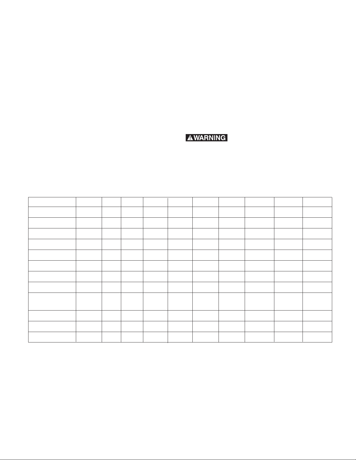
Specifications
Options Units ERD 5 ERD 10 ERD 20 ERD 35 ERD 60 ERD 100 ERD 170 ERD 300
Contents
Specifications . . . . . . . . . . . . . . . . . . . . . . . . . .2
Installation . . . . . . . . . . . . . . . . . . . . . . . . . . . . .3
Electrical Connection . . . . . . . . . . . . . . . . . . . . .3
Torque Adjustment . . . . . . . . . . . . . . . . . . . . . . .4
Maintenance . . . . . . . . . . . . . . . . . . . . . . . . . . . .4
Options . . . . . . . . . . . . . . . . . . . . . . . . . . . . . . . .5
Brake Components . . . . . . . . . . . . . . . . . . . . . .5
Dimensions . . . . . . . . . . . . . . . . . . . . . . . . . . . .6
Warranty . . . . . . . . . . . . . . . . . . . . . . .Back Page
Failure to follow these instructions may r
ment damage, and serious or fatal injury to
personnel.
esult in product damage, equip-
Holding Torque in.lb. 45 85 175 310 530 890 1500 2650
Maximum Speed RPM 3600 3600 3600 3600 3600 3600 3600 3600
Nominal Airgap Inch .008 .008 .008 .012 .012 .012 .012 .012
Maximum Airgap Inch .020 .025 .020 .030 .030 .035 .035 .040
Current Draw Amps
24 VDC 0.83 1.03 1.22 1.61 1.94 2.35 2.73 4.11
90/96/103.5 96 VDC 0.21 0.26 0.31 0.41 0.49 0.569 0.69 1.122
190/207/215 190 VDC 0.11 0.13 0.16 0.21 0.27 0.38 0.38 0.61
Resistance at
Ambient Temp. 24 VDC Ohms 28.9 23.4 19.6 14.9 12.4 10.22 8.78 5.83
90/96/103.5 96 VDC 454 372 310 233 166.2 168.6 139.2 85.63
190/207/215 190 VDC 1775 1450 1209 912 648.1 628.5 507.2 315.6
Weight Ibs 2 4 7 10 14 22 34 57
Warner Electric • 800-825-9050 819-0453
2
Page 3

Installation
ERD brakes are supplied in kit form. The magnet
assembly is supplied with airgap factory adjusted. Brakes are designed for dry operation and
can be mounted horizontally or vertically.
o
Maximum ambient temperature is 104
F.
Customer Shall Maintain:
1. Squareness of flange mounting face with
shaft within 0.006 in. (0.15mm) T.I.R. measured at the mounting shaft.
2. Concentricity of flange mounting with mounting shaft within 0.006 in. (0.15mm) T.I.R.
3. The mounting surface should be made of
steel or cast iron, square to the shaft with a
surface finish of 125 microinches or a fine
turned finish over the contact area.
Step 1
If a friction flange is provided, mount it first.
Mounting dimensions ar
Thick flanges are typical.
Step 2
Install key into shaft. Slide hub onto shaft and
ovide a suitable axial stop. Stop collars are
pr
typical.
Step 3
Slide friction disc on to hub.
Step 4
Fit magnet assembly to friction plate or prepar
ed surface. If a hand release is to be used,
this should be installed at this time. Remove
the wedge pieces. Torque bolts to the following
specifications.
ERD Size 5 10 20 35 60 100 170 300
Torque, lb.in. 20 40 70 70 210 210 210 425
e provided on Page 7.
Secure bolts using a LOCTITE 270 type thermoplastic liquid.
If a rubber dust cover is to be used, install it
before installing the magnet.
Step 5
Apply power to magnet and cycle brake on several times to confirm friction disc r
otates freely.
Verify correct airgap.
Electrical Connection
Warner Electric ERD brakes are offered in 24,
96, 190, and 215 VDC versions. Energizing the
brake magnet with the proper voltage will cause
the magnetic field generated to overcome the
brake spring force and release the brake. Any
DC power source with adequate amperage will
operate the brake. Warner Electric offers 24
VDC controls to operate standard 24 VDC
brakes and full and half wave rectifiers to supply
96 or 190 VDC current for models with those
voltage ratings. Switches are customer supplied.
The magnets are not polarity sensitive, so any
magnet lead can be connected to any power
source lead.
Recommended Warner Electric 24 VDC controls:
Model Part Number
CBC-400-24 6006-448-002
CBC-450-24
CBC-500-24 6024-448-002
CBC-550-24 6024-448-005
Warner Electric Rectifiers:
AC Input DC Output
240/220 V 96 V Half Wave CG 830
A1P1
415/380 V 190 V
A1P1
240/220 V 190 V Full Wave CG 830
A1P2
110 V 96 V Full Wave CG 830
A1P2
6006-448-005
Rectifier Part No.
Half Wave CG 830
Warner Electric • 800-825-9050 819-0453
3
Page 4

Torque Adjustment
8
5
2
4
6
3
1
9
Maintenance
Each brake is factory set to its nominal torque
rating as listed under ‘Specifications”. VAR 02
brakes are factory set at 50% of listed torque.
The torque of Variation 2 can be reduced by
loosening the central nut to the extent listed
in Figure 2.
ERD Variation 2 - lb.in. Variation 2
Size Reduction per Number of detents
detent per complete revolution
5 4.5 4
10 11 4
20 11 4
35 21 4
60 16 6
100 22 6
170 27 8
300 38 8
Wear in the friction material causes an increase
in the airgap. Before reaching the maximum airgap, it should be readjusted (see specifications).
• The brake must remain free from oil, grease,
and abrasive dust at all times.
• Check the airgap periodically and reset as
required per instructions found in Step 5 on
page 3. Inspection interval(s) depend on the
frequency of brake application.
• Check friction material thickness periodically
per dimension M and replace when below the
minimum shown below.
The theoretical reduction in airgap for 0.5 turn of
the spacer screw will be as follows:
Brake Thread Reduction Inches
ERD5 M6 X 0.5 0.25 0.010
ERD10 M8 X 0.75 0.375 0.015
ERD20 M10 X 0.75 0.375 0.015
ERD35 M10 X 0.75 0.375 0.015
ERD60 M12 X 1 0.5 0.020
ERD100 M12 X1 0.5 0.020
ERD170 M12 X 1 0.5 0.020
ERD300 M16 X 1 0.5 0.020
Table 2: Airgap Adjustment Specifications
Minimum Minimum
VAR 2
Single torque adjustment nut
VAR 0
No torque adjustment possible
ERD Size Millimeters Inches
5 0.22 0.009
10 0.21 0.008
Thickness Thickness
20 0.31 0.012
orque reduction
• T
up to 50% by
loosening nut
• Available in all sizes
Figure 2 - Torque Adjustment)
vailable in all sizes
•A
35 0.22 0.009
60 0.24 0.009
100 0.24 0.009
170 0.31 0.012
300 0.32 0.013
Table 3: Minimum Acceptable Friction Carrier
Thickness in Inches
Warner Electric • 800-825-9050 819-0453
4
Page 5

Options
Dust Cover
Airgap Adjustment
Spacer Screws
Friction
Disc Carrier
Holding Screws
Central Nut (VAR 2)
Hub
Magnet Assembly
AA
BB
EE FF
CC
Release Angle
• Manual Release - This option is recommended in applications where the brake needs to
be released by hand. This is ideal for gradually and safely lowering suspended loads in
the event of a power failure. Note: This option
requires magnet VAR 2.
• Dust Cover - This option is recommended for
use in environments which cannot be contaminated with brake friction dust and in
harsh dust, dirt, and humidity environments
where the brake is in danger from the contaminants.
• Friction Disc Carrier - Sizes 5 and 10 are
available with an optional synthetic material
carrier. Metallic disc carriers are standard for
all sizes.
• Friction Flanges - A friction flange is to be
mounted to the machine or motor frame if its
surface does not meet these specifications:
1. Cast iron or steel material
2. Hardness 150 HB
3. Smooth to 125 microinch
4. Flat to .002 inches
ERD Brake Components
Figure 1
A friction flange is required if all of the specifications are not met. The correct flange is:
Thin friction flange
Used where surface is machined but unsuitable
for friction (eg. aluminum). Used in conjunction
with "Long screw kit". Only available through
size ERD 35 due to potential distortion with frictional heat input.
Thick friction flange
Used in the absence of a suitable machined
mounting surface.
Mounting Screw Kits:
1. Short Screw Kit - supplied with the thick
2. Long Screw Kit - supplied with the thin flange
flange for mounting on the external diameter
threaded holes.
for mounting through the flange on the external diameter holes. Can also be ordered separately for direct mounting without a flange.
Figure 4 - Hand Release Lever Mounting
ERD AA BB CC EE FF Release
Size Angle
5 3.86 2.09 0.67 3.46 .040 10
10 4.21 2.44 0.71 4.17 .040 9
20 5.08 2.99 0.98 5.20 .040 8
35 5.47 3.39 0.87 5.98 .050 8
60 7.44 4.09 1.57 6.54 .050 15
100 8.07 4.72 1.73 7.36 .050 15
170 9.57 5.51 2.09 8.78 .050 15
300 12.32 6.38 2.40 10.33 .050 20
Warner Electric • 800-825-9050 819-0453
5
Page 6

f
E
F
G
0.06
B
E
H
C
J
e
P
f
h
DD
L
E
M
S
A
D
U
K
N
W
Dimensions
Brake Unit (typical)
Thin Friction Plate
Thick Friction Plate
Brake Unit (VAR 0)
Dust Cover
Figure 3
Warner Electric • 800-825-9050 819-0453
6
Page 7

Dimensions
ERD A B C D E e f F G H h J
Size Max. Bolt Patter n Bolt Bolt
Clearance Clearance
Holes Holes
5 3.307 3.268 0.787 0.5 2.835 3xM4 3x0.177 1.654 3.425 1.181 3x0.315 0.079
10 4.016 3.937 1.181 0.625 3.543 3xM5 3x0.217 2.126 4.213 1.772 3x0.394 0.079
20 5.000 4.921 1.575 1 4.409 3xM6 3x0.256 2.362 5.217 2.205 3x0.433 0.118
35 5.787 5.709 1.772 1.125 5.197 3xM6 3x0.256 2.953 6.004 2.441 3x0.433 0.118
60 6.378 6.299 2.165 1.25 5.709 3xM8 3x0.335 2.913 3x0.551 0.118
100 7.402 7.283 2.559 1.500 6.693 3xM8 3x0.335 3.307 3x0.551 0.118
170 8.465 8.346 2.953 1.95 7.717 6xM8 6x0.335 3.937 6x0.551 0.118
300 9.921 9.843 3.543 2.125 9.055 6xM10 6x0.413 4.724 6x0.670 0.118
ERD K L M N P S U W DD
Size Max. +0.000/-0.008 +/-0.002
5 1.378 1.575 0.709 0.079 0.236 0.748 0.008 0.925 3.46
10 1.614 1.831 0.787 0.118 0.276 0.945 0.008 1.122 4.17
20 1.870 2.185 0.787 0.157 0.354 1.378 0.008 1.594 5.20
35 2.146 2.559 0.984 0.118 0.354 1.575 0.012 1.909 5.98
60 2.520 2.933 1.181 0.118 0.433 1.890 0.012 2.303 6.53
100 2.795 3.209 1.181 0.118 0.433 2.047 0.012 2.500 7.56
170 3.268 3.780 1.378 0.177 0.433 2.362 0.012 2.894 8.62
300 3.819 4.528 1.575 0.197 0.433 2.874 0.012 3.484 10.8
Warner Electric • 800-825-9050 819-0453
7
Page 8

Warranty
Warner Electric LLC warrants that it will repair or replace (whichever it deems advisable) any
product manufactured and sold by it which proves to be defective in material or workmanship
within a period of one (1) year from the date of original purchase for consumer, commercial or
industrial use.
This warranty extends only to the original purchaser and is not transferable or assignable without
Warner Electric LLC’s prior consent.
Warranty service can be obtained in the U.S.A. by returning any defective product, transportation
charges prepaid, to the appropriate Warner Electric LLC factory. Additional warranty information
may be obtained by writing the Customer Satisfaction Department, Warner Electric LLC, 449
Gardner Street, South Beloit, Illinois 61080, or by calling 815-389-3771.
A purchase receipt or other proof of original purchase will be required before warranty service is
rendered. If found defective under the terms of this warranty, repair or replacement will be made,
without charge, together with a refund for transportation costs. If found not to be defective, you
will be notied and, with your consent, the item will be repaired or replaced and returned to you
at your expense.
This warranty covers normal use and does not cover damage or defect which results from
alteration, accident, neglect, or improper installation, operation, or maintenance.
Some states do not allow limitation on how long an implied warranty lasts, so the above limitation
may not apply to you.
Warner Electric LLC’s obligation under this warranty is limited to the repair or replacement of the
defective product and in no event shall Warner Electric LLC be liable for consequential, indirect,
or incidental damages of any kind incurred by reason of the manufacture, sale or use of any
defective product. Warner Electric LLC neither assumes nor authorizes any other person to give
any other warranty or to assume any other obligation or liability on its behalf.
WITH RESPECT TO CONSUMER USE OF THE PRODUCT, ANY IMPLIED WARRANTIES WHICH
THE CONSUMER MAY HAVE ARE LIMITED IN DURATION TO ONE YEAR FROM THE DATE OF
ORIGINAL CONSUMER PURCHASE. WITH RESPECT TO COMMERCIAL AND INDUSTRIAL
USES OF THE PRODUCT, THE FOREGOING WARRANTY IS IN LIEU OF AND EXCLUDES ALL
OTHER WARRANTIES, WHETHER EXPRESSED OR IMPLIED BY OPERATION OF LAW OR
OTHERWISE, INCLUDING, BUT NOT LIMITED TO, ANY IMPLIED WARRANTIES OF
MERCHANTABILITY OR FITNESS.
Some states do not allow the exclusion or limitation of incidental or consequential damages, so
the above limitation or exclusion may not apply to you. This warranty gives you specic legal
rights and you may also have other rights which vary from state to state.
Changes in Dimensions and Specifications
All dimensions and specications shown in Warner Electric catalogs are subject to change without
notice. Weights do not include weight of boxing for shipment. Certied prints will be furnished
without charge on request to Warner Electric.
Warner Electric LLC
31 Industrial Park Road • New Hartford, CT 06057
815-389-3771 • Fax: 815-389-2582
www.warnerelectric.com
P-229 819-0453 7/05 Printed in USA
 Loading...