

Page 1
P-2062-WE
SM300gb - rev 11/04
Electrically Release Brakes
ERD and ERDD
Service Manual
Page 2
We, WARNER ELECTRIC EUROPE, 7, rue Champfleur, B.P. 20095, F-49182 St Barthélemy d’Anjou Cedex
declare that these brakes are made in our factory from St Barthélemy d’Anjou,
and hereafter designated : ERD and ERDD
are exclusively designed for incorporation into a machine and to be assembled with other equipments to create a machine. The operation of the
product is submitted to the conformity of the complete equipment, following the provisions of the machinery directive 98/37/EC and if electric
to the EMC directive 89/336 /EEC. The conformity of the electric units to the Low Voltage directive 72/23 is supported by the full respect of the
following standards : NFC 79300 and VDE 05808/8.65.
Drawn up in St Barthélemy d’Anjou, July 2002
E. PRAT, General Managing Director
CONTENTS
1 Technical specifications 2
2 Precautions and restrictions on use 2
2.1 Restrictions on use 2
2.2 Precautions 3
and safety measures
3 Installation 3
3.1 Transport - storage 3
3.2 Handling 3
3.3 Installing 3
4 Maintenance 4
4.1 Adjusting the airgap 4
4.2 Adjusting the detector 4
5 Electrical connection 4
5.1 Important recommendations 4
5.2 Power supply 4
6 Options 5
6.1 Torque adjustment 5
6.2 Detection kit 5
7 Appendices 6-7
7. 1 Appendix 1 (ERD 500 to 1600 and 6
ERDD 1000 to 3200)
7. 2 Appendix 2 (ERD 3200 to 12800 and 7
ERDD 6400 to 25600)
1 Technical specifications (VAR00 and VAR03)
ERD Size 500 800 1600 3200 6400 12800
Nominal airgap mm
Airgap tolerance mm
Pull-in airgap max. mm
Tightening torque screw 909 Nm
Number of screws (Rep. 903) Handling Screws Allowable wear max* mm
0,4
± 0,005
1
48(±10%)
2xM10x80
M8
4
0,6
+0,05/-0,1
1,5
48(±10%)
4xM12x90
M12
4
0,6
+0,05/-0,1
1,5
110(±10%)
3xM16x110
M12
6,5
1
±0,1
2
150(±10%)
8xM20x120
M16
9
1,3
±0,15
2,5
260(±10%)
8xM20x140
M16
10
1,5
±0,15
380(±10%)
8XM20X180
M20
14,7
3
ERDD Size 1000 1600 3200 6400 12800 25600
Nominal airgap mm
Airgap tolerance mm
Pull-in airgap max. mm
Tightening torque screw 909 Nm
Number of screws (Rep. 903) Handling Screws Allowable wear max* mm
*See paragraphs 4-2 and 4-3
0,5
± 0,05
1
48(±10%)
2xM10x80
M8
9
0,7
+0,05/-0,1
1,5
48(±10%)
4xM12x90
M12
10,5
Table 1
0,7
+0,05/-0,1
1,5
110(±10%)
3xM16x110
M12
13,5
1,3
±0,1
2
150(±10%)
8xM20x120
M16
16,5
1,7
±0,15
2,5
260(±10%)
8xM20x140
M16
15
1,9
±0,15
3
380(±10%)
8XM20X180
M20
15,5
2 Precautions and restrictions on use
Symbol designating
an action that might
damage the brake
Symbol designating an
action that might be
dan gerous to human safety
Symbol designating an
elec trical action that might be
dangerous to human safety
2.1 Restrictions on use
These units are designed for dry operation. The
brake must be free from oil and grease.
Exceeding the maximum rotation speed listed in
the catalogue will invalidate the guarantee.
2 Warner Electric Europe • +33 (0)2 41 21 24 24 P-2062-WE • 2/13
ERD 500, ERD 800 and ERD 1600 can be hori-
zontally or vertically mounted, all other units can
only be mounted horizontally.
Ambient temperature for these units is
max 40° C (insulation class of 155°C).
Page 3
2.2 Precautions and safety measures
During the maintenance period make sure
that the moving parts of the machine are
stationary and that there is no risk of start-up.
All intervention have to be made by qualified
personnel, owning this manual.
It is imperative that the release screws (903) are
mounted before any operation is made to the
unit.
Any modification made to the brake without
the express authorisation of a representative of
Warner Electric, in the same way than any use
out of the contrac tual specifications accepted
by “Warner Electric”, will result in the warranty
being invalidated and Warner Electric will
no longer be liable in any way with regard to
conformity.
3 Installation
Slide the hub (515) onto the shaft to be braked,
fit the driving key and secure it axially.
Keep the driving splines free of oil (i.e. friction
disc / hub). Otherwise this may reduce
performance.
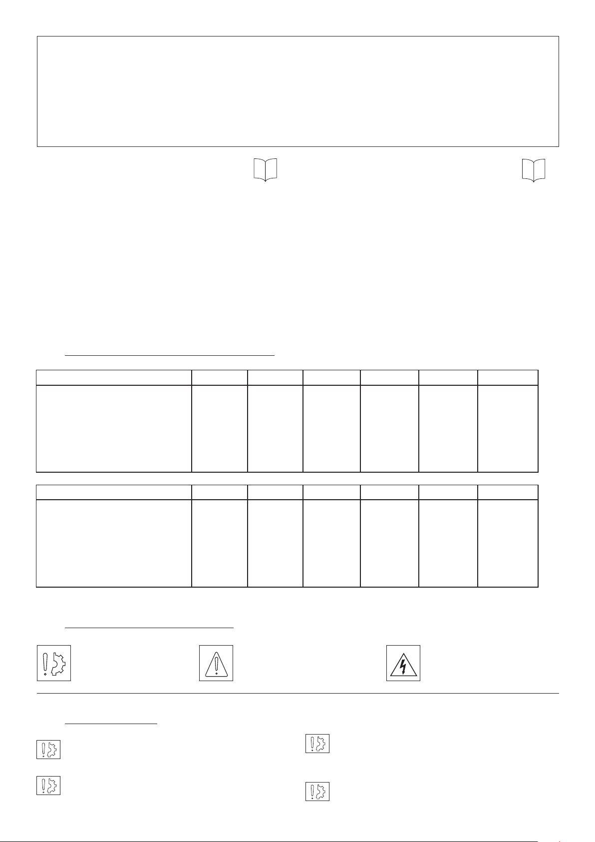
It is important to note the hub mounting
directions (See Fig. 2).
ERD
ERDD
3.1 Transport / storage
These units are delivered in packaging that
guarantees a 6 months storage period whether
transported by land, by air, or by sea to any
destination excepting tropical countries. (For
tropical destinations please consult Warner
Electric technical services).
3.2 Handling
The unit is supplied pre-assembled except for
the hub.
Do not expose the unit to shocks whilst
handling as this may reduce performance.
Use the handling
holes provided for
Handling
screw
any operation (See
Fig. 1, table 1).
Never transport
the unit by the
cable.
3.2 Installation
Fig. 1
Fig. 2
The hub is normally supplied with the following
norms : tolerances H7 for bore, P9 for keyways
(According to NF E 22-175/DIN 6885/BS 4235/ISO
R773).
Fit the friction plate (348) onto the mounting
surface. For single disc brakes from size 3200 and
for dual disc brakes from size 6400, the friction
plate is directly fixed on the mount with CHC
screws (not provided) and secure them with a
LOCTITE 270 product.
Now install the friction disc (312). If this is a dual
disc brake, then fit the intermediate disc (320) or
(321) and finally install the second friction disc
(according to size).
NOTE: The angle of the friction discs must be
facing the friction plate (see Fig. 2).
Slide the pre-campled moving armature (330) /
inductor (101) between the friction faces and fix
it with locking screws (909) and washers noting
carefully the tightening torque (see table 1 page 2).
To mount the unit proceed as follows: according
to types, (see appendices 1 or 2):
Remove release screws (903). Energize the unit
(see chapter 5) and check if the friction disc
rotates freely.
Compress springs with release screws (903).
The moving armature (330) must be pulled
against the inductor (101).
Energise the brake a number of times whilst the
motor is static and check the nominal airgap value
(See table 1 page 2) near the faces of the friction
Loosen the locking screws (909), the friction
plate (348), the friction disc(s) (312) and the
plate (348). If insufficient airgap, see chapter 4
(maintenance)
intermediate disc (320) or (321) for brakes with
dual discs.
Warner Electric Europe • +33 (0)2 41 21 24 24 P-2062-WE • 2/13 3
Page 4

4 Maintenance
4.1 Airgap setting
Electric leads must be large enough to prevent
voltage drops between power supply and the
unit.
To adjust the airgap (see appendix 1 or 2), loosen
the lock ing screws (909), then turn the adjusting
screws (902) adjusting to the airgap required.
Tighten the locking screws (909) to the required
torque (see table 1).
Check the airgap value again at various points
near the faces of the friction plate.
Energise the brake a number of times whilst the
motor is static, re-check the airgap value at the
various points.
4.2 Maintenance
Friction material wear generates an increase
in the airgap value. To reach the maximum airgap
(see table 1), it is necessary to set it (see Chapter
4.1).
4.3 Spare parts
After continued operation varying according to
unit size and use, it may become necessary to
replace
one or more friction discs when the minimum
value Y is reached (see Fig. 3 and table 2).
I (A) / L (m) 0 to 10 m von 10 to 20 m
0 to 3 (A) 1,5 mm2 1,5 mm
3 to 6 (A) 1,5 mm2 2,5 mm
2
2
Supply voltage tolerances on the brake : +5% /
-10% (NF C 79-300)
5.2 Power supply
We recommend the use of Warner Electric power
supply CBC 140-5 (with over-excitation and
handling voltage).
The switch on/switch off process has a major
effect on the response time. Response times
listed in the catalogue refers to nominal supply
voltage with switching on DC side.
If switching on the AC side, the response time in
braking can be multiplied by 6.
• If over-excitation occurs during drop-out, the
pull-indistance can be divided by 3
(depending on net voltage).
• When the operating voltage falls to
50% of the nominal value it reduces braking
response time and working temperature.
Y
Fig. 3
ERD 500 800 1600 3200 6400 12800
Y min (mm)
ERDD 1000 1600 3200 6400 12800 25600
Y min (mm)
To proceed see chapter 3-3. Re-adjustment of the
airgap is necessary (see chapter 4.1).
5 Electrical connection
The brakes ERD & ERDD must be supplied with
D.C volt- age and are fitted with a 500 mm length
cable. Polarity does not affect the functioning.
5.1 Important recommendations
2 2 2 3 4,5 3
3 3 3,5 3,5 3 3
Table 2
Warner Electric power supplies are designed to
protect the coils and circuitry. If the brake is used
power off with switching on DC side, it is essential
to protect the coil with a varistor mounted in
parallel.
All works on the electrical connections have to be
made with power off.
Note carefully the nominal supply voltage (low
sup- ply voltage generates low pull-in
distance).
4 Warner Electric Europe • +33 (0)2 41 21 24 24 P-2062-WE • 2/13
Page 5
6 Options
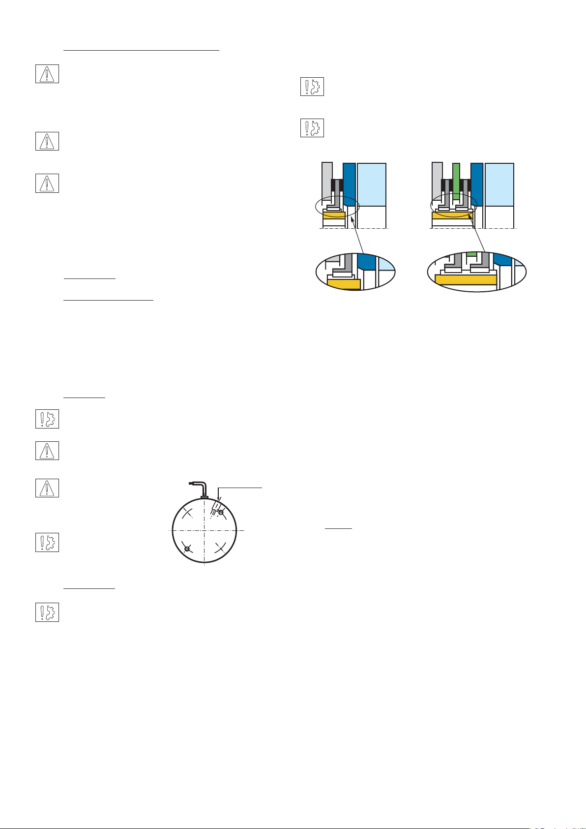
6.1 Torque adjustment
Only possible with VAR03. The brakes are
delivered adjusted with nominal torque value.
M ± 0.1
Principle of torque reduction
(See table 3 and Fig. 4). Unscrew the
adjusting cap located behind the inductor
Fig. 4
without exceeding the dimension M min.
Table 3 (for VAR03 only)
ERD Sizes 500 800 1600 3200 640-0 12800*
Nominal Torque Nm
Dinension M (
±0,1mm)
mm
Torque min. Nm
Dinension M min. (
±0,1mm)
mm
500
13,7
360
0
800
17,1
580
5,1
1600
27,3
1180
15,3
3200
14,5
2550
5,5
6400
-
-
-
12800
Theoretic reduction of nom. torque
for 1 round of adjusting cap %
4
4
5
6
-
ERDD Sizes 1000 1600 3200 6400 12800* 25600*
Nominal Torque Nm
Dinension M (
±0,1mm)
mm
Torque min. Nm
Dinension M min. (
±0,1mm)
mm
1000
13,7
700
0
1600
17,1
1200
5,1
3200
27,3
2350
15,3
6400
14,5
5600
5,5
12800
-
-
-
25600
Theoretic reduction of nom. torque
for 1 round of adjusting cap %
4
4
5
6
-
-
-
-
-
-
-
-
-
* NOTE: for ERD 6400 & 12800 and ERDD 12800 & 25600, the torque is reduced by removing the springs. This operation is carried out in our plants.
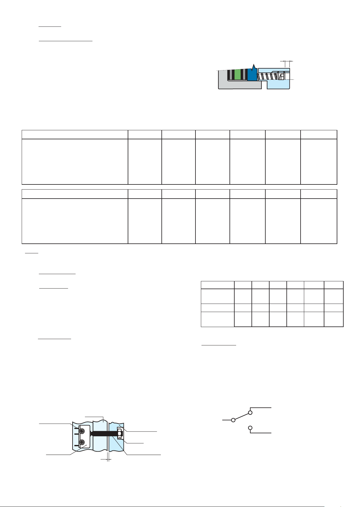
6.2 Detection kit
Mounting:
Check that the brake is correctly adjusted with
nominal airgap. Fit the M6 screw in the moving
armature and mount the nut (see Fig. 5), fit the
sensor with the M3 screws and washers.
Table 4
ERD 500 800 1600 3200 6400 12800
Dimension X
(± 0,05 mm)
ERDD 1000 1600 3200 6400 12800 25600
Dimension X
(± 0,05 mm)
0,2 0,4 0,4 0,7 1 1
0,2 0,4 0,4 0,7 1 1
Adjustment
Switch Data
Insert a feeler gauge in gap X (see table 4)
between the inductor and the moving armature.
Switch the brake on, and adjust the screw until
you obtain action on the sensor, then tighten the
Protection Class IP 65
Temperature -40°C / +120°C
Cable 3 x 0,75 mm
Switching 8A - 250 VAC / 6A - 380 VAC
locking nut. Check the unit works correctly with
successive pull-in and pull-outs.
Control position
Red
Screw
washer M3
Switch
Magnet
Moving
Armature
Nut
X
M6 screw
Black
Blue
2 positions
Fig. 5
Warner Electric Europe • +33 (0)2 41 21 24 24 P-2062-WE • 2/13 5
Page 6

7 Appendices
7.1 Appendix 1
Rep. Designation
101 Magnet
312 Friction disc
320 Intermediate disc
330 Moving armature
348 Friction plate
515 Hub
740 Spring
902 Adjusting screw
903 Release screw
909 Locking screw
917 Transport nut
921 Washer
935 Adjust cap
917
312
515
348
ERD 500 to 1600
330
max. wear
903
921
909
101
740
935
902
917
312
515
320
348
ERDD 1000 to 3200
AirgapAirgap
330
max. wear
903
921
909
101
740
935
902
6 Warner Electric Europe • +33 (0)2 41 21 24 24 P-2062-WE • 2/13
Page 7

7.2 Appendix 2
Rep. Designation
101 Magnet
312 Friction disc
321 Furnished intermediate disc
322 Mounted friction lining
330 Moving armature
348 Friction disc
515 Hub
740 Spring
902 Adjusting screw
903 Release screw
909 Locking screw
921 Washer
935 Adjust cap
960 Push
312
515
322
348
max. wear
ERD 3200 to 12800
330
921
909
101
740
921
903
960
935
902
312
322
515
320
321
348
ERDD 6400 to 25600
AirgapAirgap
330
max. wear
921
909
101
740
921
903
960
935
902
Warner Electric Europe • +33 (0)2 41 21 24 24 P-2062-WE • 2/13 7
Page 8

Warranty
Warner Electric LLC warrants that it will repair or replace (whichever it deems advisable) any product manufactured and
sold by it which proves to be defective in material or workmanship within a period of one (1) year from the date of original
purchase for consumer, commercial or industrial use.
This warranty extends only to the original purchaser and is not transferable or assignable without Warner Electric LLC’s
prior consent.
Warranty service can be obtained in the U.S.A. by returning any defective product, transportation charges prepaid, to
the appropriate Warner Electric LLC factory. Additional warranty information may be obtained by writing the Customer
Satisfaction Department, Warner Electric LLC, 449 Gardner Street, South Beloit, Illinois 61080, or by calling 815-389-
3771.
A purchase receipt or other proof of original purchase will be required before warranty service is rendered. If found
defective under the terms of this warranty, repair or replacement will be made, without charge, together with a refund for
transportation costs. If found not to be defective, you will be notified and, with your consent, the item will be repaired or
replaced and returned to you at your expense.
This warranty covers normal use and does not cover damage or defect which results from alteration, accident, neglect, or
improper installation, operation, or maintenance.
Some states do not allow limitation on how long an implied warranty lasts, so the above limitation may not apply to you.
Warner Electric LLC’s obligation under this warranty is limited to the repair or replacement of the defective product and
in no event shall Warner Electric LLC be liable for consequential, indirect, or incidental damages of any kind incurred by
reason of the manufacture, sale or use of any defective product. Warner Electric LLC neither assumes nor authorizes any
other person to give any other warranty or to assume any other obligation or liability on its behalf.
WITH RESPECT TO CONSUMER USE OF THE PRODUCT, ANY IMPLIED WARRANTIES WHICH THE CONSUMER MAY
HAVE ARE LIMITED IN DURATION TO ONE YEAR FROM THE DATE OF ORIGINAL CONSUMER PURCHASE. WITH
RESPECT TO COMMERCIAL AND INDUSTRIAL USES OF THE PRODUCT, THE FOREGOING WARRANTY IS IN LIEU
OF AND EXCLUDES ALL OTHER WARRANTIES, WHETHER EXPRESSED OR IMPLIED BY OPERATION OF LAW OR
OTHERWISE, INCLUDING, BUT NOT LIMITED TO, ANY IMPLIED WARRANTIES OF MERCHANTABILITY OR FITNESS.
Some states do not allow the exclusion or limitation of incidental or consequential damages, so the above limitation or
exclusion may not apply to you. This warranty gives you specific legal rights and you may also have other rights which
vary from state to state.
Changes in Dimensions and Specications
All dimensions and specifications shown in Warner Electric catalogs are subject to change without notice. Weights do not
include weight of boxing for shipment. Certified prints will be furnished without charge on request to Warner Electric.
Warner Electric Europe
7 rue Champfleur, B.P. 20095, St Barthelemy d’Anjou - France
+33 (0)2 41 21 24 24 • Fax: +33 (0)2 41 21 24 70
www.warnerelectric.com
Printed in USAP-2062-WE • 2/13
 Loading...