

Page 1
kgf
mm
mm
mm
mm
kgf
kg
m
N*m
lbf kN m/min ft/min m/min ft m
1
18000 80.1 3.1 14.9 4.5 21 6.4
2
14727 65.5 3.8 18.2 5.5 46 14.0
3
12461 55.4 4.5 21.5 6.6 75 22.9
* Never exceed the Rated Pulling Force. Installation of a Rated Capacity Limiter is recommended.
Duty Cycle
lbf kgf BAR min/10min
0 0 11.2 N/A
3000 1361 27.6 N/A
6000 2722 45.7 N/A
9000 4082 64.1 N/A
12000 5443 82.5 N/A
15000 6804 106.6 N/A
18000 8165 125.2 N/A
102
253inin
Line Speed 15 GPM
Wire Rope Tension Plate 10''
Fairlead Black 10''
Fairlead Chrome 10"
Remote Clutch Air
Remote Clutch Mechanical
Wire Rope Assembly 1/2''x75'
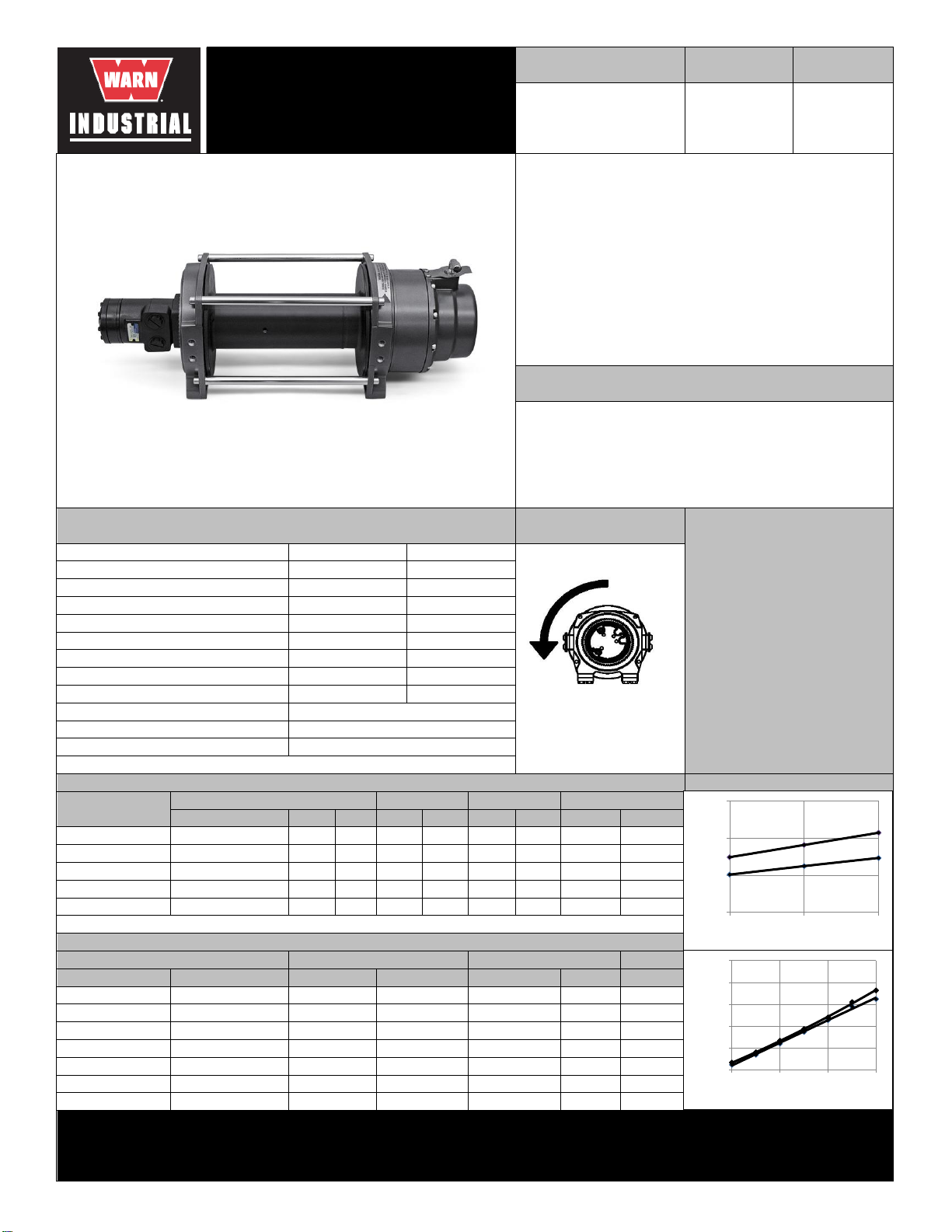
Drum Rotation
lbf
18000
1. -SAE J706
2.-CE Machinery Directive 98/37/EC and
2006/42/EC
Part Number
Model
Series 18-A-73
Hydraulic Winch
Manual Clutch
drum rotation image
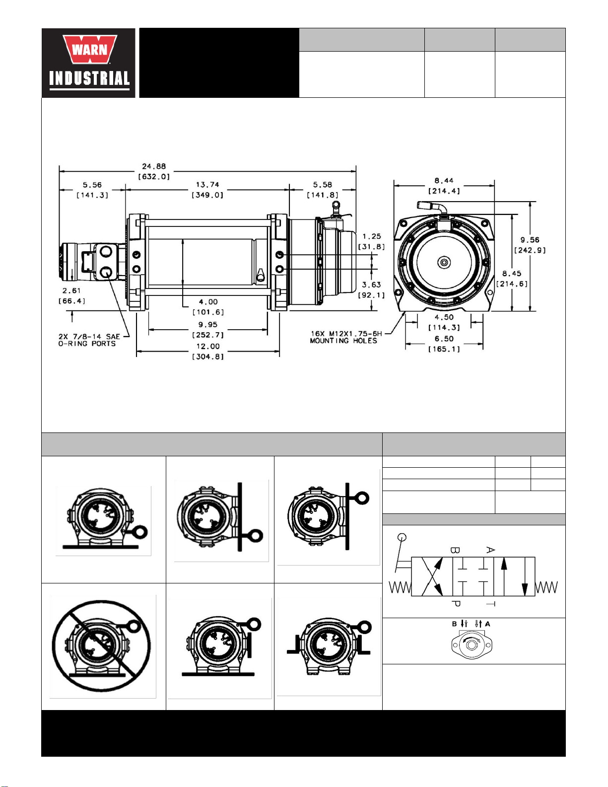
Drum Barrel Diameter:
1/2
26600
Recommended Minimum Wire Rope Breaking Strength:
Rated Pulling Force:
4.00
Drum Capacity
Motor Type
Hydraulic
7.3 ci
(120 cc)
74125
WARN Industrial Winch
Standards
Compliance
31149
24336
30859
71370
38316
77534
Part Number
product photo
The Series 18 hydraulic winch features a 2 stage planetary gear train with a
total reduction of 36:1. This winch uses a heavy duty automatic disc brake
and a locking clutch lever. The 4'' (102mm) steel drum provides excellent
durability for the wire rope. Designed to meet SAE J706 and CE standards.
Accessories
Engineering Data
Description:
47 - 54
37.2
ft*lbf
8165
209inin
12.7
Contactor / Remote Type: N/A
lbf
12066
912514.C1 2/2013
930
663
linespeed graph
pressure drop graph
Customer Service (North America): 1.800.543.9276
Customer Service (International): 1.503.722.3008
FAX: 1.503.722.3000 www.warn.com
41.3
12900 S.E. Capps Road,
Clackamas, OR USA 97015
1617
78.4
867
345
First Layer Performance
1816
1196
1546
99.7
WARN INDUSTRIES, INC
Industrial Products
kgf
5652
111.5
1446
1137
599
Line Load
psi
162
psi
Pressure Drop at 15 GPM
59.8
6680
Performance By Layer- 1/2" (12.7 mm) dia. rope
3 (with 1/2" dia. rope)
Mounting Bolt Torque:
ft
82.0
Drum Layer
23.8
400
7.8
Pressure Drop at 10 GPM
113
14.7
BAR
Viewed from Motor End
Line Speed 10 GPM
ft/min
Line Load *
8165
10.2
12.5
Drum Flange Diameter:lb36:1
Gear Reduction: 36 :1
35 - 40
9.95
Brake Type: Disc
Disk
565
Duty Cycle (intermittent per SAE J706 section 6.2):
Approximate Shipping Weight:
Maximum Layers of Wire Rope:
172
Distance Between Flanges:
8.24
Recommended Maximum Wire Rope Diameter:
0.0
10.0
20.0
30.0
1 2 3
Line Speed (ft/min)
Layer
15 GPM
10 GPM
0
500
1000
1500
2000
2500
0 6000 12000 18000
Pressure Drop (psi)
Line Load (lbf)
15 GPM
10 GPM
Page 2
Maximum System Pressure: 2400 psi 166 BAR
Maximum Motor Pressure Drop: 1816 psi 125 BAR
Maximum Rated Input Flow: 15 GPM 57 LPM
image
912514.C1 2/2013
12900 S.E. Capps Road,
Clackamas, OR USA 97015
Customer Service (North America): 1.800.543.9276
Customer Service (International): 1.503.722.3008
FAX: 1.503.722.3000 www.warn.com
WARN INDUSTRIES, INC
Industrial Products
image
Note: Drum rotates clockwise with Port A pressurized when viewed
from gearbox end.
Feet down without angle brace
image
image
Feet forward
Feet down
Hydraulic System Specifications
Hydraulic
7.3 ci
(120 cc)
Units are given in inches [millimeters], unless otherwise specified
Pull from top of winch
Pull from bottom of winch
WARN Industrial Winch
Motor / Contactor may be rotated in 90 degree increments. Clutch housing may be rotated in 72 degree increments.
outline drawing
Series 18-A-73
Hydraulic Winch
Manual Clutch
Pull from bottom of winch
Motor Type
Model
74125
Part Number
Recommended Mounting- Always Observe Correct Drum Rotation
Pull from top of winch
image
Control Valve Schematic
Angle Braces Only
3-position, 4-way, closed
center, spring return
(cylinder spool)
schematic
Control Valve Type:
Pull from top of winch
Feet forward
Pull from top of winch
Feet down with angle brace
image
 Loading...