

Page 1

WALTHER PILOT
Betriebsanleitung, Operating Instructions
Mode d’emploi, Instrucciones de Servicio
Bedieningshandleiding, Betjeningsvejledning
Spritzpistole / Spray gun / Pistolet de pulvérisation
Pistola de pulverización / Spuitpistool / Sprøjtepistoler
PILOT Rapid
REV. 01/12
Page 2

Stand Juli 2008
PILOT Rapid
2 3
Page 3

Inhaltsverzeichnis
Explosionszeichnung 2
EG-Konformitätserklärung 5
Ersatzteilliste 6
EG-Konformitätserklärung
Wir, der Gerätehersteller, erklären in alleiniger Verantwortung, dass das Produkt
in der untenstehenden Beschreibung den einschlägigen grundlegenden Sicherheitsund Gesundheitsanforderungen entspricht. Bei einer nicht mit uns abgestimmten
Änderung an dem Gerät oder bei einer unsachgemäßen Verwendung verliert diese
Erklärung ihre Gültigkeit.
1 Allgemeines 8
1.1 Kennzeichnung der Modelle 8
1.2 Bestimmungsgemäße Verwendung 8
1.3 Sachwidrige Verwendung 9
2 Technische Beschreibung 9
3 Sicherheitshinweise 10
3.1 Kennzeichnung der Sicherheitshinweise 10
3.2 Allgemeine Sicherheitshinweise 10
4 Versorgungsleitungen anschließen 11
5 Inbetriebnahme / Bedienung 12
6 Umrüstung / Instandsetzung 13
7 Reinigung 14
8 Fehlersuche und -beseitigung 15
8.1 Mängel des Spritzbildes beheben 15
9 Entsorgung 16
10 Technische Daten 16
Hersteller WALTHER Spritz- und Lackiersysteme GmbH
Kärntner Str. 18 - 30
D - 42327 Wuppertal
Tel.: +49(0)202 / 787 - 0
Fax: +49(0)202 / 787 - 2217
www.walther-pilot.de • e-mail: info@walther-pilot.de
Typenbezeichnung Modelle: Handspritzpistolen PILOT Rapid, - MP
Rapid Materialanschluss V 10 172
Rapid-MP Materialanschluss V 10 174
Verwendungszweck Verarbeitung spritzbarer Materialien
Angewandte Normen und Richtlinien
EG-Maschinenrichtlinien 2006 / 42 / EG
94 / 9 EG (ATEX Richtlinien)
EN ISO 12100 Teil 1
EN ISO 12100 Teil 2 DIN EN 1953
DIN EN 1127-1 DIN EN 13463-1
Spezifikation im Sinne der Richtlinie 94 / 9 / EG
Kategorie 2 Gerätebezeichnung
Bevollmächtigt mit der Zusammenstellung der technischen Unterlagen:
Nico Kowalski, WALTHER Spritz- und Lackiersysteme GmbH, Kärntner Str. 18 - 30
D- 42327 Wuppertal
Besondere Hinweise :
Das Produkt ist zum Einbau in ein anderes Gerät bestimmt. Die Inbetriebnahme ist
so lange untersagt, bis die Konformität des Endproduktes mit der Richtlinie 2006 /
42 / EG festgestellt ist.
II 2 G c T 6
Tech.File,Ref.:
2401
Wuppertal, den 01. Januar 2010
i.V.
Name: Torsten Bröker
Stellung im Betrieb: Leiter der Konstruktion und Entwicklung
Diese Erklärung ist keine Zusicherung von Eigenschaften im Sinne der Produkthaftung. Die
Sicherheitshinweise der Produktdokumentation sind zu beachten.
4 5
Page 4

Ersatzteilliste PILOT Rapid
PILOT Rapid
Materialanschluss
V 10 172 02 . . 3 V 10 174 02 . . 3
Pos. Bezeichnung Stck Artikelnummer Stck Artikelnummer
Luftkopf
Düsengröße 0,3 bis 1,5 mm ø*
1
Düsengröße 1,8 bis 2,2 mm ø*
Materialdüse*
2
Nadelpackung komplett
3
Nadelstopfbuchse
3.1
Nadelpackung
3.2
3.3 Druckstück 1 V 10 151 37 000 1 V 10 151 37 000
4 Pistolenkörper komplett 1 V 10 172 01 000 1 V 10 174 01 000
5 Ventilschaftdichtung 1 V 10 170 20 000 1 V 10 170 20 000
6 Ventilkegel komplett 1 V 10 170 14 000 1 V 10 170 14 000
7 Ventilfeder 1 V 10 170 30 000 1 V 10 170 30 000
8 Scheibe 1 V 10 151 18 000 1 V 10 151 18 000
9 O-Ring 1 V 09 102 33 009 1 V 09 102 33 009
10 O-Ring 1 V 09 103 22 001 1 V 09 103 22 001
11 Federbuchse 1 V 10 151 16 005 1 V 10 151 16 005
12 Materialnadel* 1 V 10 152 71 . . 3* 1 V 10 152 71 . . 3*
13 Nadelfeder 1 V 10 151 53 000 1 V 10 151 53 000
Stellschraube
14
(Materialmenge)
15 Regelschraube komplett 1 V 11 700 11 000 1 V 11 700 11 000
16 O-Ring 1 V 09 103 14 001 1 V 09 103 14 001
17 Spindelbuchse 1 V 11 700 12 100 1 V 11 700 12 100
18 Packung 1 V 09 101 02 020 1 V 09 101 02 020
19 Stopfbuchse 2 V 10 302 02 000 2 V 10 302 02 000
20 Stellknopf (Luftmenge) 1 V 11 700 13 000 1 V 11 700 13 000
21 Zylinderschraube 1 V 11 700 13 100 1 V 11 700 13 100
22 Dichtkegel 1 V 10 170 10 200 1 V 10 170 10 200
23 Gewindebuchse 1 V 10 170 10 100 1 V 10 170 10 100
24 O-Ring 1 V 09 102 02 007 1 V 09 102 02 007
Stellschraube (Rund -/
25
Breitstrahl)
8-Loch
V 10 151 30 039* V 10 141 30 038*
1
V 10 151 30 189* V 10 141 30 188*
V 10 151 41 . . 3*
1
V 10 151 00 500
1
V 10 151 06 103
1
V 09 002 21 000
1
1 V 10 151 19 005 1 V 10 151 19 005
1 V 10 170 10 300 1 V 10 170 10 300
6 7
PILOT Rapid-MP
Materialanschluss
1
Mitteldruck
V 10 151 41 . . 3*
1
V 10 151 00 500
1
V 10 151 06 103
1
V 09 002 21 000
1
Ersatzteilliste PILOT Rapid
PILOT Rapid
Materialanschluss
V 10 172 02 . . 3 V 10 174 02 . . 3
Pos. Bezeichnung Stck Artikelnummer Stck Artikelnummer
26
Senkschraube
27 Doppelnippel 1 V 00 101 70 005 1 V 00 101 70 005
28 Materialanschlussnippel 1 V 10 152 16 003 1 V 10 152 16 003
29 Sicherungsscheibe 2 V 11 601 23 000 2 V 11 601 23 000
30 Hebelschaftschraube 1 V 10 151 11 005 1 V 10 151 11 005
31 Mitnehmerbolzen 1 V 10 151 12 005 1 V 10 151 12 005
32 Hebelschraube 1 V 10 301 09 000 1 V 10 301 09 000
33 Abzugshebel 1 V 10 171 10 000 1 V 10 171 10 000
34 Federscheibe 1 V 11 700 26 200 1 V 11 700 26 200
1 V 10 170 25 003 1 V 10 170 25 003
Reparatursets
WALTHER hält für die Handspritzpistolen PILOT Rapid und Rapid MP Reparatursets bereit, die
sämtliche Verschleißteile enthalten. Diese Teile sind in der Ersatzteilliste mit Fettdruck gekennzeichnet.
PILOT Rapid
Standard-Version V 16 172 NA ..3
Materialanschluss (FA)
PILOT Rapid-MP
Mitteldruck-Version V 16 174 NA ..3
Materialanschluss (FA)
Düsenausstattung nach Wahl: ▪ 0,3 • 0,5 • 0,8 • 1,0 • 1,2 • 1,5 • 1,8 • 2,0 • 2,2 mm ø
Düsensets
Düsensets bestehen aus Luftkopf, Materialdüse und Materialnadel.
PILOT Rapid Materialanschluss (FA) V 15 172 04 ..3
PILOT Rapid-MP Materialanschluss (FA) V 15 174 NA ..3
Düsenausstattung nach Wahl: ▪ 0,3 • 0,5 • 0,8 • 1,0 • 1,2 • 1,5 • 1,8 • 2,0 • 2,2 mm ø
*Bei Ersatzteillieferung bitte entsprechende Größe angeben.
( Ø 0.3, 0.5, 0.8, 1.0, 1.2, 1.5, 1.8, 2.0, 2.2 mm )
Wir empfehlen, Reparatursets auf Lager zu halten.
PILOT Rapid-MP
Materialanschluss
Artikelnummer
Artikelnummer
Page 5

1 Allgemeines
1.1
Modelle: Handspritzpistolen PILOT Rapid (Hochdruck)
Handspritzpistolen PILOT Rapid-MP (Mitteldruck)
Typ: PILOT Rapid Materialanschluss V 10 172
PILOT Rapid-MP Materialanschluss V 10 174
Hersteller: WALTHER Spritz- und Lackiersysteme GmbH
Kärntner Str. 18-30
D-42327 Wuppertal
Telefon: 00 49 / 2 02 / 787-0
Telefax: 00 49 / 2 02 / 787-2217
www.walther-pilot.de • Email:info@walther-pilot.de
1.2 Bestimmungsgemäße Verwendung
Die Handspritzpistole PILOT Rapid dient ausschließlich der Verarbeitung spritzbarer
Medien, wie z.B.:
• Lacke und Farben
• Fette, Öle und Korrosionsschutzmittel
• Keramikglasuren
• Beizen
Sind die Materialien, die Sie verspritzen wollen, hier nicht aufgeführt, wenden Sie
sich bitte an WALTHER Spritz- und Lackiersysteme GmbH, Wuppertal. Die spritzbaren Materialien dürfen lediglich auf Werkstücke bzw. Gegenstände aufgetragen werden. Die Temperatur des Spritzmaterials darf 43°C grundsätzlich nicht überschreiten.
Die bestimmungsgemäße Verwendung schließt auch ein, dass alle Hinweise und
Angaben der vorliegenden Betriebsanleitung gelesen, verstanden und beachtet werden.
Das Gerät erfüllt die Explosionsschutz-Forderungen der Richtlinie 94 / 9 EG (ATEX)
für die auf dem Typenschild angegebene Explosionsgruppe, Gerätekategorie und
Temperaturklasse. Beim Betreiben des Gerätes sind die Vorgaben dieser
Betriebsanleitung unbedingt einzuhalten.
Die vorgeschriebenen Inspektions- und Wartungsintervalle sind einzuhalten.
Die Angaben auf den Geräteschildern bzw. die Angaben in dem Kapitel technische
Daten sind unbedingt einzuhalten und dürfen nicht überschritten werden. Eine
Überlastung des Gerätes muss ausgeschlossen sein.
Das Gerät darf in explosionsgefährdeten Bereichen nur nach Maßgabe der zuständigen Aufsichtsbehörde eingesetzt werden.
Der zuständigen Aufsichtsbehörde bzw. dem Betreiber obliegt die Festlegung
der Explosionsgefährdung (Zoneneinteilung).
Es ist betreiberseitig zu prüfen und sicherzustellen, dass alle technischen Daten
und die Kennzeichnung gemäß ATEX mit den notwendigen Vorgaben übereinstimmen.
Bei Anwendungen, bei denen der Ausfall des Gerätes zu einer Personengefährdung
führen könnten, sind betreiberseitig entsprechende Sicherheitsmaßnahmen vorzusehen.
Falls im Betrieb Auffälligkeiten erkannt werden, muss das Gerät sofort stillgesetzt
werden und es ist mit WALTHER Spritz- und Lackiersysteme Rücksprache zu halten.
Erdung / Potentialausgleich
Es muss sichergestellt werden, dass die Spritzpistole über einen leitfähigen Luftschlauch ausreichend geerdet ist (maximaler Wiederstand 10
6
Ω).
1.3 Sachwidrige Verwendung
Die Spritzpistole darf nicht anders verwendet werden, als es im Abschnitt bestimmungsgemäße Verwendung geschrieben steht. Jede andere Verwendung ist sachwidrig.
Zur sachwidrigen Verwendung gehören z.B.:
• das Verspritzen von Materialien auf Personen und Tiere
• das Verspritzen von flüssigem Stickstoff.
2 Technische Beschreibung
PILOT Rapid: Spritzpistole für konventionelle Zerstäubung.
Ausführungen: • mit Materialanschluss.
PILOT Rapid-MP: Spritzpistole für Mitteldruck
Ausführungen: • mit Materialanschluss.
Bei einem Eingangsdruck von 3,0 bis 3,3 bar beträgt der Spritzdruck 1,2 bis 1,4
bar.
Bei Betätigung des Abzughebels (Pos. 33) wird zuerst der Ventilkegel (Pos. 6)
geöffnet (Vorluft) und dann erst die Materialnadel (Pos. 12) zurückgezogen.
Das Schließen erfolgt in umgekehrter Reihenfolge.
Die Materialdurchflussmenge ist abhängig vom Durchmesser der Düse und der Einstellung des Materialdruckes am Druckgefäß oder Materialdruckregler. Zusätzlich
läßt sich die Materialmenge durch Ein- bzw. Ausschrauben der Stellschraube
(Pos. 14) regeln.
Die Stellschraube (Pos. 25) dient zur Regulierung der Spritzstrahlbreite.
Der Spritzstrahl wird durch Linksdrehen (Ausschrauben) zum Breitstrahl,
Die Stellknopf (Pos. 20) dient zur Regulierung der Zerstäuberluftmenge.
durch Rechtsdrehen (Einschrauben) zum Rundstrahl.
8 9
Page 6
3 Sicherheitshinweise
3.1 Kennzeichnung der Sicherheitshinweise
Verwenden Sie nur Original-Ersatzteile, da WALTHER nur für diese eine sichere und
einwandfreie Funktion garantieren kann.
Warnung
Das Piktogramm und die Dringlichkeitsstufe “Warnung“ kennzeichnen eine mögliche
Gefahr für Personen.
Mögliche Folgen: schwere oder leichte Verletzungen.
Achtung
Das Piktogramm und die Dringlichkeitsstufe “Achtung“ kennzeichnen eine mögliche
Gefahr für Sachwerte.
Mögliche Folgen: Beschädigung von Sachen.
Hinweis
Das Piktogramm und die Dringlichkeitsstufe “Hinweis“ kennzeichnen zusätzliche
Informationen für das sichere und effiziente Arbeiten mit der Spritzpistole.
3.2 Allgemeine Sicherheitshinweise
Die einschlägigen Unfallverhütungsvorschriften sowie die sonstigen anerkannten
sicherheitstechnischen und arbeitsmedizinischen Regeln sind einzuhalten.
Benutzen Sie die Spritzpistole nur in gut belüfteten Räumen. Im Arbeitsbereich ist
Feuer, offenes Licht und Rauchen verboten. Beim Verspritzen leichtentzündlicher
Materialien (z. B. Lacke, Kleber, Reinigungsmittel usw.) besteht erhöhte
Gesundheits-, Explosions- und Brandgefahr.
Es muss sichergestellt werden, dass die Spritzpistole über einen leitfähigen Luftschlauch ausreichend geerdet ist (maximaler Wiederstand 10
Schalten Sie vor jeder Wartung und Instandsetzung die Luft- und Materialzufuhr zur
Spritzpistole drucklos - Verletzungsgefahr.
Halten Sie beim Verspritzen von Materialien keine Hände oder andere Körperteile vor
die unter Druck stehende Düse der Spritzpistole - Verletzungsgefahr.
Richten Sie die Spritzpistole nicht auf Personen und Tiere - Verletzungsgefahr.
Beachten Sie die Verarbeitungs- und Sicherheitshinweise der Hersteller von
Spritzmaterial und Reinigungsmittel. Insbesondere aggressive und ätzende
Materialien können gesundheitliche Schäden verursachen.
Die partikelführende Abluft ist vom Arbeitsbereich und Betriebspersonal fernzuhalten.
Tragen Sie dennoch vorschriftsgemäßen Atemschutz und vorschriftsgemäße
Arbeitskleidung, wenn Sie mit der Spritzpistole Materialien verarbeiten.
Umherschwebende Partikel gefährden Ihre Gesundheit.
Tragen Sie im Arbeitsbereich der Spritzpistole einen Gehörschutz. Der erzeugte
Schallpegel der Spritzpistole beträgt ca. 85 dB (A) (PILOT Rapid) bzw. ca. 83 dB (A)
(PILOT Rapid-MP).
Achten Sie stets darauf, dass bei Inbetriebnahme, insbesondere nach Montage- und
Wartungsarbeiten alle Muttern und Schrauben fest angezogen sind.
10 11
6
Ω).
Bei Nachfragen zur gefahrlosen Benutzung der Spritzpistole sowie der darin verwendeten Materialien, wenden Sie sich bitte an WALTHER Spritz- und Lackiersysteme
GmbH, D-42327 Wuppertal.
4 Versorgungsleitungen anschließen
Hinweis
Zur Durchführung der im Folgenden aufgeführten Arbeitsschritte benutzen Sie bitte
die Explosionszeichnung (Faltblatt) am Anfang dieser Betriebsanleitung.
Warnung
Der an der Pistole anstehende Luftdruck darf 8 bar nicht überschreiten, da sonst kein
funktionssicherer Betrieb der Spritzpistole gewährleistet ist.
Warnung
Material- und Luftschläuche, die mit einer Schlauchtülle befestigt werden, müssen
zusätzlich mit einer Schlauchschelle gesichert sein.
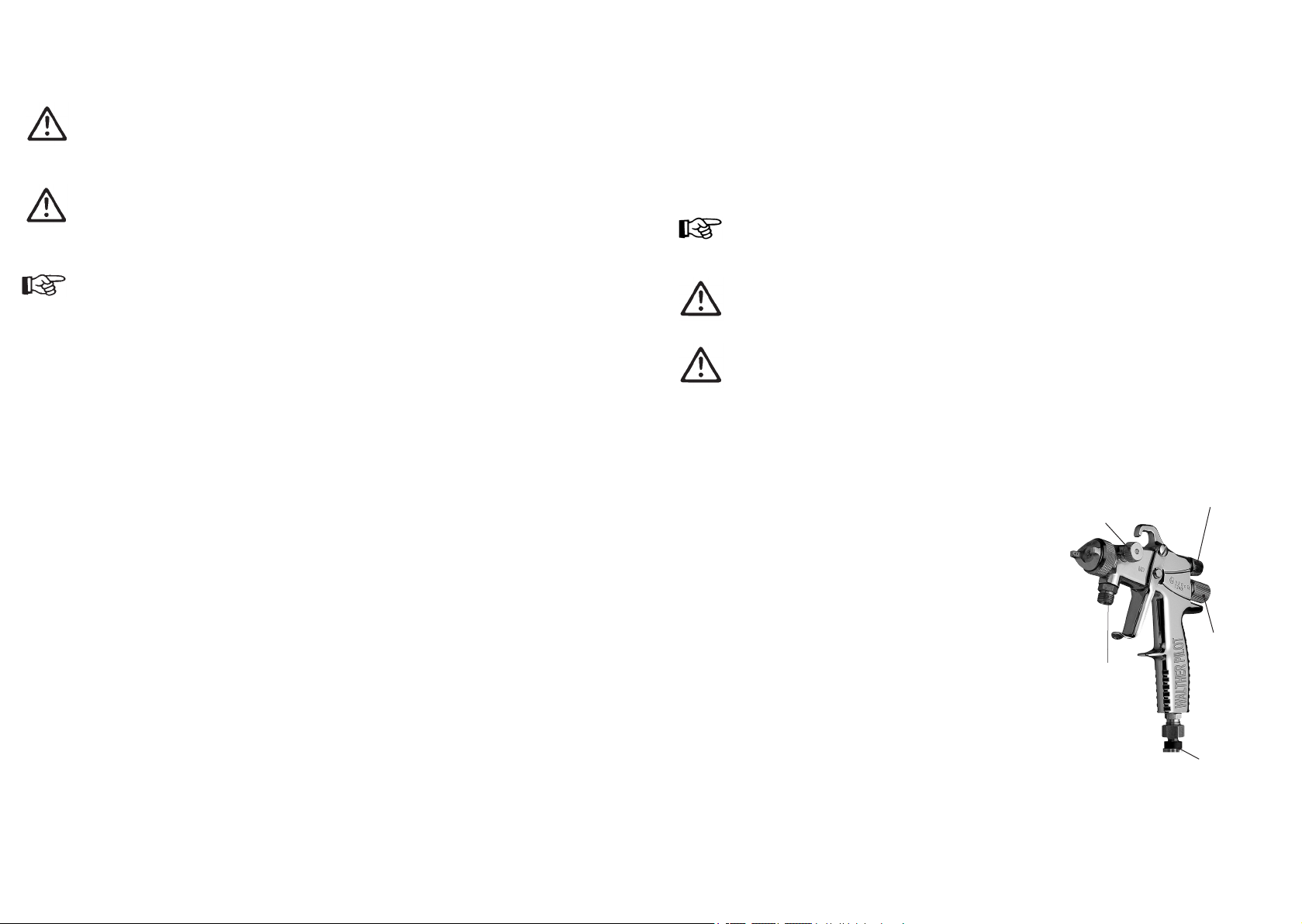
Ausführung:
Materialzuführung durch Druckgefäß
1. Befestigen Sie den Druckluftschlauch an der
Luftleitung (gereinigte Druckluft) und an dem
Luftanschluss der Spritzpistole (Pos. 27).
Rund - /
BreitstrahlRegulierung
2. Befestigen Sie den Materialzuführungsschlauch
am Materialdruckgefäß bzw. Materialdruckregler
einer Pumpenanlage und an dem
Materialanschluss (Pos. 28) der Spritzpistole.
3. Füllen Sie Material in das Materialdruckgefäß
und verschließen Sie den Deckel.
4. Stellen Sie am Druckluftreduzierventil den
gewünschten Materialdruck ein; bei
Materialzufuhr über Pumpensysteme wird der
Materialdruck am Materialdruckregler einge-
Materialanschluss
stellt.
5. Schalten Sie die Druckluft ein und stellen Sie
am Reduzierventil den gewünschten
Zerstäuber luftdruck ein.
6. Öffnen Sie den Materialhahn am Druckgefäß.
7. Um die im Materialschlauch befindliche Luft
entweichen zu lassen, betätigen Sie den
Abzugshebel (Pos. 33) solange, bis ein gleichmäßiger Materialstrahl aus der
Düse tritt; nun kann die Pistole wieder geschlossen werden.
Die Pistole ist nun betriebsbereit.
Luftmengenregulierung
Materialmengenregulierung
(Nadelhub)
Luftanschluss
Page 7

5 Inbetriebnahme / Bedienung
6 Umrüstung / Instandsetzung
Bevor Sie die Spritzpistole in Betrieb setzen können, müssen folgende Voraussetzungen erfüllt sein:
• Der Zerstäuberluftdruck muss an der Spritzpistole anstehen
• Der Materialdruck muss an der Spritzpistole anstehen
Achtung
Der Materialdruck darf nicht höher eingestellt sein als
• 8 bar, da sonst kein funktionssicherer Betrieb der Spritzpistole gewährleistet ist.
Warnung
Die Spritzpistole muss nach Arbeitsende immer drucklos geschaltet werden. Die
unter Druck stehenden Leitungen können platzen und nahestehende Personen
durch das ausströmende Material verletzen.
Spritzbildprobe
Eine Spritzbildprobe sollte immer dann erzeugt werden, wenn:
• die Spritzpistole zum erstenmal in Betrieb gesetzt wird.
• das Spritzmaterial ausgetauscht wird.
• die Pistole zur Wartung oder Instandsetzung zerlegt wurde.
Die Spritzbildprobe kann auf ein Probewerkstück, Blech, Pappe oder Papier abgegeben werden.
Spritzbild verändern:
Sie können an der PILOT Rapid durch die folgenden Einstellungen das Spritzbild
verändern (siehe auch Abbildungen Seite 5).
a) Breit- bzw. Rundstrahl einstellen
Regulierung der Spritzstrahlbreite an der Stellschraube (Pos. 25):
• durch Linksdrehen (Ausschrauben) zum Breitstrahl,
• durch Rechtsdrehen (Einschrauben) zum Rundstrahl.
b) Materialdurchflussmenge einstellen
Die Materialmenge läßt sich durch Ein- bzw. Ausschrauben der Stellschraube
(Pos. 14) regeln. Sie wird durch Linksdrehen (Ausschrauben) erhöht, durch
Rechtsdrehen (Einschrauben) verringert.
c) Zerstäuberluft regulieren
Die Zerstäuberluftmenge läßt sich durch Ein- bzw. Ausschrauben der Stellknopf
(Pos. 20) regulieren. Der Zerstäuberluftdruck wird am Druckluft-Reduzierventil
der Kompressoranlage eingestellt. Beachten Sie die Anweisungen und
Sicherheitshinweise des Herstellers. Wenn Sie das Spritzbild über die bereits
erwähnten Möglichkeiten hinaus verändern wollen, muss die Spritzpistole umgerüstet werden. WALTHER bietet dazu eine Vielzahl unterschiedlicher Luftkopf- /
Materialdüse-/ Nadel-Kombinationen an.
Warnung
Schalten Sie vor jeder Umrüstung / Instandsetzung die Steuer- und Zerstäuberluft
sowie die Materialzufuhr zur Spritzpistole drucklos - Verletzungsgefahr.
Hinweis
Zur Durchführung der im Folgenden aufgeführten Arbeitsschritte benutzen Sie bitte
die Zeichnung am Anfang dieser Betriebsanleitung.
Materialdüse und Luftkopf wechseln
1. Schrauben Sie den Luftkopf (Pos. 1) vom Pistolenkörper (Pos. 4).
2. Schrauben Sie die Materialdüse (Pos. 2) mit Schlüssel SW 7 aus dem
Pistolenkörper aus.
Die Montage der neuen Materialdüse erfolgt in umgekehrter Reihenfolge.
Materialnadel wechseln
1. Schrauben Sie die Stellschraube (Pos. 14) ab.
2. Entnehmen Sie die Nadelfeder (Pos. 13).
3. Ziehen Sie die Materialnadel (Pos. 12) aus dem Pistolenkörper.
Die Montage erfolgt in umgekehrter Reihenfolge.
Undichte Nadelpackung austauschen
1. Entfernen Sie die Materialnadel, -düse und Luftkopf wie oben beschrieben.
2. Schrauben Sie mit einem Schraubendreher die Nadelstopfbuchse (Pos. 3.1) aus dem
Pistolenkörper. (Benutzen Sie evtl. das Spezialwerkzeug ).
3. Ziehen Sie die Nadelpackung komplett (Pos. 3) {Nadelstopfbuchse (Pos. 3.1),
Nadelpackung (Pos. 3.2), Druckstück (Pos. 3.3)} aus dem Pistolenkörper
Benutzen Sie hierzu evtl. einen dünnen Draht, dessen Ende zu einem Haken
umgebogen ist.
Die Montage erfolgt in umgekehrter Reihenfolge
Hinweis
Die aus dem Pistolenvorsatz entnommene Nadelpackung darf nicht wieder verwendet
werden, da sonst eine funktionssichere Dichtwirkung nicht gewährleistet ist.
Hinweis
Alle beweglichen und gleitenden Bauteile müssen vor dem Einbau in den Pistolenkörper mit einem säurefreien, nicht harzenden Fett eingefettet werden.
12 13
Page 8
7 Reinigung
8 Fehlersuche und -beseitigung
Achtung
Legen Sie die Spritzpistole nie in Lösemittel oder ein anderes Reinigungsmittel.
Die einwandfreie Funktion der Spritzpistole kann sonst nicht garantiert werden.
Verwenden Sie zur Reinigung keine harten oder spitzen Gegenstände.
Für Schäden, die aus unsachgemäßer Reinigung herrühren, übernimmt
WALTHER, Wuppertal, keine Gewährleistung.
Sie können die Spritzpistole reinigen, ohne diese dabei zerlegen zu müssen.
1. Befüllen Sie den gesäuberten Materialbehälter / Fließbecher / Saugbecher /
Hängedruckbecher bzw. das gesäuberte Materialdruckgefäß mit einem zum
verspritzten Material passenden Reinigungsmittel.
2. Setzen Sie die Spritzpistole in Betrieb.
3. Setzen Sie die Spritzpistole erst außer Betrieb, wenn diese nur noch klares
Reinigungsmittel verspritzt.
Die gesamte Spritzanlage ist bis zum nächsten Einsatz drucklos zu schalten.
Verwenden Sie zur Reinigung der Spritzpistole nur Reinigungsmittel, die vom
Hersteller des Spritzmaterials angegeben werden und die folgenden Bestandteile
nicht enthalten:
• halogenierte Kohlenwasserstoffe
(z. B. 1,1,1, Trichlorethan, Methylen-Chlorid usw.)
• Säuren und säurehaltige Reinigungsmittel
• regenerierte Lösemittel (sog. Reinigungsverdünnungen)
• Entlackungsmittel.
Die o.g. Bestandteile verursachen an galvanisierten Bauteilen chemische
Reaktionen und führen zu Korrosionsschäden.
Reinigen Sie die Spritzpistole
• vor jedem Farb- bzw. Materialwechsel.
• mindestens einmal wöchentlich.
• materialabhängig und je nach Verschmutzungsgrad mehrfach wöchentlich.
Ausführliche Reinigung
1. Zerlegen Sie die Pistole.
2. Reinigen Sie den Luftkopf und die Materialdüse mit einem Pinsel und dem
Reinigungsmittel.
3. Reinigen Sie alle übrigen Bauteile und den Pistolenkörper mit einem Tuch
und dem Reinigungsmittel.
4. Bestreichen Sie folgende Teile mit einem dünnen Fettfilm:
• Nadelfeder.
• alle gleitenden Teile und Lagerstellen.
Die beweglichen Innenteile sind wenigstens einmal wöchentlich zu fetten. Die Federn sollten ständig mit einem leichten Fettüberzug versehen sein. Verwenden Sie
dazu ein säurefreies, nicht harzendes Fett und einen Pinsel. Anschließend wird
die Spritzpistole in umgekehrter Reihenfolge zusammengesetzt.
Warnung
Unterbrechen Sie vor jeder Umrüstung die Luft- und Materialzufuhr zur
Spritzpistole - Verletzungsgefahr.
Fehler Ursache Abhilfe
Pistole tropft
Stoßweiser oder
flatternder Spritzstrahl
Pistole bläst
in Ruhestellung
Materialnadel o. -düse beschädigt
Materialnadel o. -düse verschmutzt
Nadelstopfbuchse (Pos. 3.1) zu
fest ange zogen
zu wenig Material im Behälter
Fließbecher wird zu stark geneigt
Materialdüse (Pos. 2) ist lose
oder beschädigt
Ventilfeder (Pos. 7) oder
Ventilkegel (Pos. 6) beschädigt
auswechseln
reinigen
mit Schraubendreher
etwas lösen
auffüllen
gerader halten
festziehen oder austauschen
austauschen
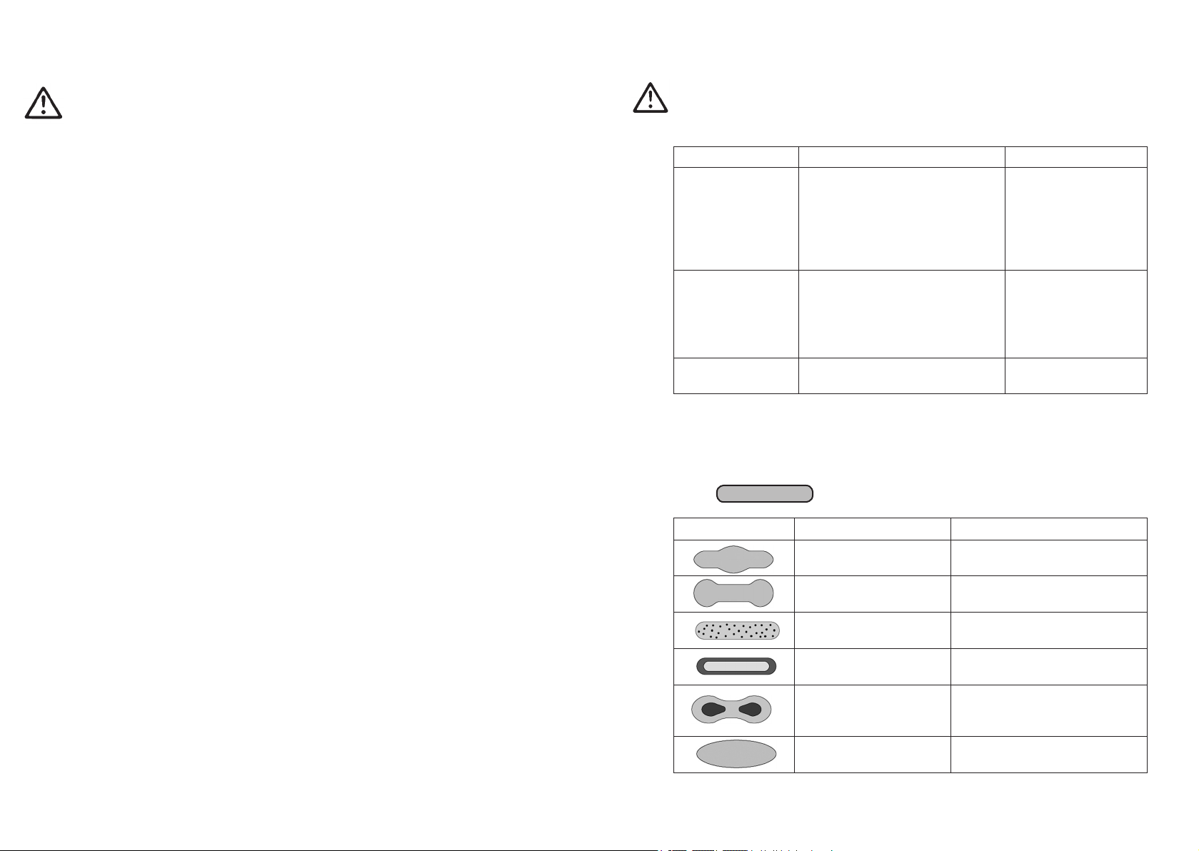
8.1 Mängel eines Spritzbildes beheben
Die folgende Tabelle zeigt Ihnen, mit welchen Einstellungen Sie das Spritzbild
beeinflussen können.
angestrebtes Spritzergebnis
Spritzbildprobe Abweichung erforderliche Einstellung
Spritzbild ist in der Mitte
zu dick
Spritzbild ist an den
Enden zu dick
Spritzbild ist ziemlich
grobtropfig
Materialauftrag ist in der
Spritzbildmitte sehr dünn
Spritzbild ist in der Mitte
gespalten
Spritzbild ist sehr ballig • Materialdruck verringern
• breitere Spritzstrahlform
einstellen
• rundere Spritzstrahlform
einstellen
• Zerstäuberluftdruck
erhöhen
• Zerstäuberluftdruck
verringern
• Düsendurchmesser erhöhen
• Zerstäuberluftdruck verringern
• Materialdruck erhöhen
• Zerstäuberluftdruck erhöhen
14 15
Page 9

9 Entsorgung
Die bei der Reinigung und Wartung anfallenden Materialien sind den Gesetzen
und Vorschriften entsprechend sach- und fachgerecht zu entsorgen.
Warnung
Beachten Sie insbesondere die Hinweise des Herstellers der Spritz- und
Reinigungsmittel. Unachtsam entsorgtes Material gefährdet die Gesundheit von
Mensch und Tier.
10 Technische Daten
Gewicht: 400 g
Düsenaustattung
nach Wahl: 0,3 • 0,5 • 0,8 • 1,0 • 1,2 • 1,5 • 1,8 • 2,0 • 2,2 mm
Luftköpfe: Hochdruckluftkopf 8-Loch
Mitteldruckkopfkopf
Max. Zerstäuberluftdruck: 8 bar
Max. Materialdruck: 8 bar
Max. Betriebstemperatur
der Spritzpistole: 43°C
Der Schallpegel,
gemessen in 1 m Abstand,
beträgt: 83 / 85 dB(A)
Technische Änderungen vorbehalten.
16
Page 10
Contents
Exploded Drawing 2
Declaration of CE-Conformity 19
Spare Parts List 20
1 General Information 22
1.1 Identification of Model Version 22
1.2 Normal Use 22
1.3 Improper Use 23
2 Technical Description 23
3 Safety Instructions 24
3.1 Identification of safety instructions 24
3.2 General Safety Instructions 24
4 Assembly 25
5 Operation 26
6 Retooling and Repairs 27
7 Cleaning and Maintenance 28
8 Troubleshooting 29
8.1 Correcting spray pattern flaws 29
9 Disposal of Cleaning and Servicing Substances 30
10 Technical Data 30
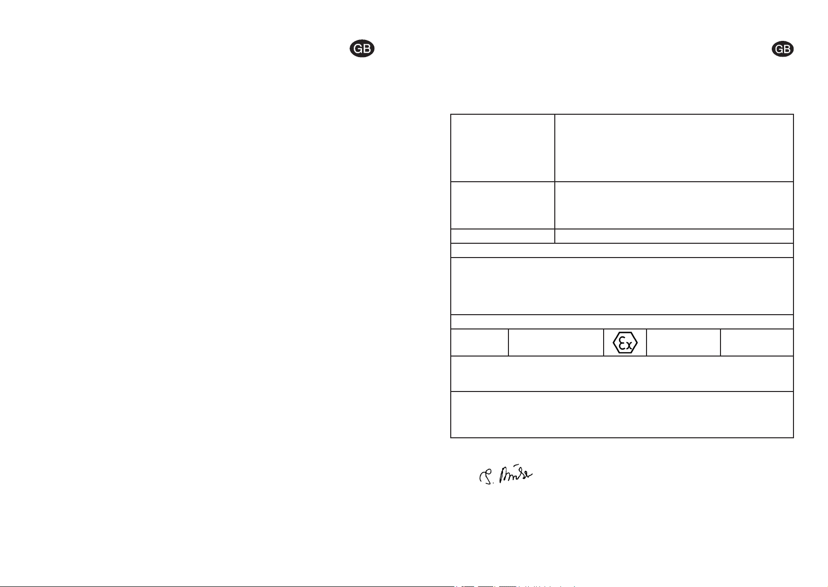
Declaration of CE-Conformity
We, the manufacturers of the equipment, hereby declare under our sole responsibility that the product(s) described below conform to the essential safety requirements.
This declaration will be rendered invalid if any changes are made to the equipment without prior consultation with us.
Manufacturer WALTHER Spritz- und Lackiersysteme GmbH
Kärntner Str. 18 - 30
D - 42327 Wuppertal
Tel.: +49(0)202 / 787 - 0
Fax: +49(0)202 / 787 - 2217
www.walther-pilot.de • e-mail: info@walther-pilot.de
Type Designation Models:Hand-held Spray Guns PILOT Rapid, - MP
Rapid Material Connection V 10 172
Rapid-MP Material Connection V 10 174
Intended purpose Processing of sprayable media
Applied Standards and Directives
EU-Mechanical Engineering Directives 2006 / 42 / EC
94 / 9 EC (ATEX Directives)
EN ISO 12100-1
EN ISO 12100-2 DIN EN 1953
DIN EN 1127-1 DIN EN 13463-1
Specification according 94 / 9 / EC
Category 2 Part marking
Authorized with the compilation of the technical file:
Nico Kowalski, WALTHER Spritz- und Lackiersysteme GmbH, Kärntner Str. 18 - 30
D- 42327 Wuppertal
Special remarks :
The named product is intended for installation in other equipment. Commissioning is
prohibited until such time as the end product has been proved to conform to the provision of the Directives 2006 / 42 / EC.
II 2 G c T 6
Tech.File,Ref.:
2401
Wuppertal, the 1st of January 2010
i.V.
Name: Torsten Bröker
Position: Manager, Design and Development
This Declaration does not give assurance of properties in the sense of product liability. The safety instructions
provided in the product documentation must be observed at all times.
18 19
Page 11

Replacement parts PILOT Rapid
PILOT Rapid
Material connection
V 10 172 02 . . 3 V 10 174 02 . . 3
Item Description Qty. Art. No. Qty. Art. No.
Air Control Head
for nozzles 0.3 - 1.5 mm ø* V 10 151 30 039* V 10 141 30 038*
1
for nozzles 1.8 - 2.2 mm ø* V 10 151 30 189* V 10 141 30 188*
Material Outlet Nozzle*
2
Needle Seal Packing compl.
3
Needle Packing Gland
3.1
Needle Seal Packing
3.2
3.3 Thrust Ring 1 V 10 151 37 000 1 V 10 151 37 000
4 Gun Body compl. 1 V 10 172 01 000 1 V 10 174 01 000
5 Valve Stem Seal 1 V 10 170 20 000 1 V 10 170 20 000
6 Valve Cone compl. 1 V 10 170 14 000 1 V 10 170 14 000
7 Valve Spring 1 V 10 170 30 000 1 V 10 170 30 000
8 Washer 1 V 10 151 18 000 1 V 10 151 18 000
9 O-Ring 1 V 09 102 33 009 1 V 09 102 33 009
10 O-Ring 1 V 09 103 22 001 1 V 09 103 22 001
11 Spring Retaining Bush 1 V 10 151 16 005 1 V 10 151 16 005
12 Material Control Needle* 1 V 10 152 71 . . 3* 1 V 10 152 71 . . 3*
13 Needle Spring 1 V 10 151 53 000 1 V 10 151 53 000
Needle Adjusting Screw
14
(Material Flow Rate)
15 Adjusting Screw compl. 1 V 11 700 11 000 1 V 11 700 11 000
16 O-Ring 1 V 09 103 14 001 1 V 09 103 14 001
17 Spindle Bushing 1 V 11 700 12 100 1 V 11 700 12 100
18 Packing 1 V 09 101 02 020 1 V 09 101 02 020
19 Stuffing Gland 2 V 10 302 02 000 2 V 10 302 02 000
20 Adjusting Knob (Air Flow Rate) 1 V 11 700 13 000 1 V 11 700 13 000
21 Cylinder Head Screw 1 V 11 700 13 100 1 V 11 700 13 100
22 Conical Nipple 1 V 10 170 10 200 1 V 10 170 10 200
23 Threated bush 1 V 10 170 10 100 1 V 10 170 10 100
24 O-Ring 1 V 09 102 02 007 1 V 09 102 02 007
Adjusting Screw
25
(Flat - / Round - Jet)
1
8-Loch
V 10 151 41 . . 3*
1
V 10 151 00 500
1
V 10 151 06 103
1
V 09 002 21 000
1
1 V 10 151 19 005 1 V 10 151 19 005
1 V 10 170 10 300 1 V 10 170 10 300
PILOT Rapid-MP
Material connection
1
Medium pre.
V 10 151 41 . . 3*
1
V 10 151 00 500
1
V 10 151 06 103
1
V 09 002 21 000
1
20 21
Replacement parts PILOT Rapid
PILOT Rapid
Materialanschluss
V 10 172 02 . . 3 V 10 174 02 . . 3
Item. Description Qty. Art. No. Qty. Art. No.
26 Counter Sunk Screw 1 V 10 170 25 003 1 V 10 170 25 003
27 Double Nipple 1 V 00 101 70 005 1 V 00 101 70 005
28 Material Inlet 1 V 10 152 16 003 1 V 10 152 16 003
29 Lock Washer 2 V 11 601 23 000 2 V 11 601 23 000
30 Trigger Shank Screw 1 V 10 151 11 005 1 V 10 151 11 005
31 Driver Pin 1 V 10 151 12 005 1 V 10 151 12 005
32 Trigger Screw 1 V 10 301 09 000 1 V 10 301 09 000
33 Trigger 1 V 10 171 10 000 1 V 10 171 10 000
34 Spring Washer 1 V 11 700 26 200 1 V 11 700 26 200
Repair Sets
WALTHER supplies repair sets containing all wearing parts for the hand-held spray guns PILOT
Rapid and Rapid MP. This wearing parts are shown in boldface print in the list of the replacement parts.
PILOT Rapid
Standard-version V 16 172 NA ..3
Material connection (FA)
PILOT Rapid-MP
Medium-pressure-version V 16 174 NA ..3
Material connection (FA)
Nozzle sizes optional: ▪ 0,3 • 0,5 • 0,8 • 1,0 • 1,2 • 1,5 • 1,8 • 2,0 • 2,2 mm ø
Nozzle Sets
Nozzle sets consist of air control head, material nozzle and material needle.
PILOT Rapid Material connection (FA) V 15 172 04 ..3
PILOT Rapid-MP Material connection (FA) V 15 174 NA ..3
Nozzle sizes optional: ▪ 0,3 • 0,5 • 0,8 • 1,0 • 1,2 • 1,5 • 1,8 • 2,0 • 2,2 mm ø
* Please quote the respective sizes when ordering replacements.
( Ø 0.3, 0.5, 0.8, 1.0, 1.2, 1.5, 1.8, 2.0, 2.2 mm )
We recommand that repair sets are held on stock.
PILOT Rapid-MP
Materialanschluss
Art. No.
Art. No.
Page 12

1 General Information
1.1 Identification of Model Version
Models: Hand-held Spray Guns PILOT Rapid (high pressure)
Hand-held Spray Guns PILOT Rapid-MP (medium pressure)
Type: PILOT Rapid Material Connection V 10 172
PILOT Rapid-MP Material Connection V 10 174
Manufacturer: WALTHER Spritz- und Lackiersysteme GmbH
Kärntner Str. 18-30
D-42327 Wuppertal • Germany
Phone: 00 49 / 2 02 / 787-0
Fax: 00 49 / 2 02 / 787-2217
www.walther-pilot.de • Email:info@walther-pilot.de
1.2 Normal Use
The hand-held spray gun PILOT Rapid is designed exclusively for use with sprayable
media, including water-based and aggressive media, such as:
The operator must check and ensure that all technical data and the marking of the
equipment in accordance with ATEX are compliant with the necessary requirements.
The operator must provide corresponding safety measures for all applications in
which the breakdown of the equipment might lead to danger to persons.
If any irregularities are observed while the equipment is in operation, the equipment must be put out of operation immediately and WALTHER Spritz- und
Lackiersysteme must be consulted.
Grounding / Equipotential Bonding
Measures must be taken to ensure that the spray gun is sufficiently grounded
(earthed) by means of a conductive air hose (maximum resistance 10
6
Ω).
1.3 Improper Use
The spray gun must not be used for purposes other than those laid down in the
above section 1.2 Normal Use.
Any other form of use is prohibited.
Improper use includes
• the spraying of material on persons and animals;
• the use of liquid nitrogen.
• paints and laquers
• greases, oils and corrosion preventives
• ceramic glazes
• pickling solutions
If you have any questions, please contact WALTHER Spritz- und Lackiersysteme
GmbH, Wuppertal.
Sprayable material should only be applied to work pieces or similar objects.
The temperature of the material to be sprayed should at no time exceed 43° C.
The term 1.2 Normal Use also implies that any and all safety warnings and instructions laid down in these operating instructions have been read, understood and are
duly complied with.
This equipment complies with the explosion protection requirements of Directive
94/9/EC (ATEX) for the explosion group, equipment category and temperature class
indicated on the type plate. When using the equipment, the requirements specified in
these Operating Instructions must be observed at all times.
The technical data indicated on the equipment rating plates and the specifications in
the chapter „Technical Data“ must be complied with at all times and must not be
exceeded. An overloading of the equipment must be ruled out.
The equipment may be used in potentially explosive atmospheres only with the
authorisation of the relevant supervisory authority.
The relevant supervisory authority or the operator of the equipment are
responsible for determining the explosion hazard (zone classification).
22 23
2 Technical Description
PILOT Rapid: Manual spray gun for conventional atomisation
Model versions: • with material connection
PILOT Rapid-MP: Manual spray gun for medium pressure
Model versions: • with material connection.
With the PILOT Rapid-MP the spraying pressure is from 1.2 to 1.4 bar with an input
pressure of 3.0 to 3.3 bar.
Pulling of the trigger (item 33) is followed by opening of the valve cone (item 6)
(initial air input) with subsequent pull-back of the material control needle (item
12). Releasing of the trigger shuts the gun off in reverse order.
The material flow rate depends on the diameter of the nozzle used and on the setting of the material pressure at the material pressure tank or at the material pressure regulating control.
The material input volume may also be regulated at the needle adjusting screw
(item 14) by turning it inwards or outwards.
The spray-jet adjuster (item 25) is used to control the spray jet ratio, i.e.
LH-turn (outwards) = flat jet,
RH-turn (inwards)
The air volume regulating control (item 20) is used to adjust the atomizing air
input.
= round jet.
Page 13

3 Safety instructions
3.1 Identification of safety instructions
Warning
The pictogram and the urgency level “Warning“ identify a possible danger to persons.
Possible consequences: Slight to severe injuries.
Attention
The pictogram and the urgency level “Attention“ identify a possible danger to material assets.
Possible consequences: Damage to material assets.
Use only original replacement parts, since WALTHER can only guarantee safe and
fault-free operation for original parts.
For further information on the safe use of the spray gun and the spraying materials,
please contact WALTHER Spritz- und Lackiersysteme GmbH, D-42327 Wuppertal,
Germany.
4 Assembly
Note
Use the exploded view at the beginning of these operating instruction to perform the
operational steps described hereafter.
Note
The pictogram and the urgency level “Note“ identify additional information for the
safe and efficient operation of the spray gun.
3.2 General Safety Instructions
All applicable accident prevention rules and regulations as well as other recognised
industrial safety and health rules and regulations must be observed at all times.
Use the spray gun only in well-ventilated rooms. Fire, naked flames and smoking
are strictly prohibited within the working area. WARNING – during the spraying of
flammable materials (e.g. lacquers, adhesives, cleaning agents, etc.), there is an
increased risk to health as well as an increased risk of explosion and fire.
Measures must be taken to ensure that the spray gun is sufficiently grounded
(earthed) by means of a conductive air hose (maximum resistance 10
Before carrying out maintenance or servicing work, always ensure that the air and
material feed to the spray gun have been de-pressurised. Risk of injury!
When spraying materials, do not place your hands or other parts of the body in front
of the pressurised nozzle or the spray gun. Risk of injury!
Never point the spray gun at persons or animals. Risk of injury!
Always observe the spraying and safety instructions given by the manufacturers of
the spraying material and the cleaning agent. Aggressive and corrosive materials in
particular can be harmful to health.
Exhaust air containing particles (overspray) must be kept away from the working
area and personnel. In spite of these measures, always wear the regulation breathing masks and protective overalls when using the gun. Airborne particles represent a serious health hazard!
Always wear hearing protection when using the gun or when in the vicinity of a gun
that is in use. The noise level generated by the spray gun is approx. 85 dB (A)
(PILOT Rapid) or approx. 83 dB (A) (PILOT Rapid-MP).
After carrying out assembly or maintenance work, always ensure that all nuts, bolts
and screw connections have been fully tightened before the gun is used.
6
Ω).
Warning
The air pressure at the gun shall not exceed 8 bar; otherwise a safe operation of
the spray gun cannot be ensured.
Warning
Material and air hoses which are installed with a hose grommet must be additionally
secured with a hose clamp.
Design Version: External Material Input
1. Connect the pressure-air hose between the
air supply system (cleaned pressure-air) and
the gun air inlet reducer (item 27).
Flat-/
Round-Jet
Adjustment
2. Connect the material input hose between the
material pressure tank and/ or the material
pressure regulating control of a pumping
system and the material inlet (item 28) of the
gun.
3. Fill the material pressure tank with material
and close the lid.
4. Set the desired material pressure at the air
pressure reduction valve; if the material is
supplied via pump systems, the material
Material
Connection
pressure is adjusted via the adjustment
wrench at the material pressure control.
5. Swith on the pneumatic system and set the
desired atomizing air pressure at the reduction valve.
6. Open the material tap at the pressure tank.
7. Pull the trigger (item 33) of the gun to evacuate all air trapped inside the material input hose. Wait until the material exits in an even flow from the gun and
shut the gun off.
The gun is now ready for operation.
Atomizing air
Material
Flow Rate
(Needle
Range)
Air Connection
24 25
Page 14

5 Operation
6 Retooling and Repairs
The following requirements must be met before the spray gun is operated:
• The atomizing air pressure must be available at the gun,
• The material pressure must be available at the gun.
Caution
The material pressure should not exceed
• 8 bar,since otherwise the operational reliability of the spray gun will be impaired.
Warning
It is important to remember to relieve the spray gun of all pressures when work is
terminated. Lines left under pressure may burst and the released material may
cause injuries.
Spray Pattern Test
Spray pattern tests should be performed whenever:
• the spray gun is taken into operation for the first time;
• the spraying medium is changed;
• the spray gun was taken apart for maintenance or repair works.
The spray pattern is best tested using a workpiece sample, a sheet of metal,
cardboard or paper.
Spray Pattern Adjustment:
The spray pattern of the spray guns of Model Series PILOT Rapid may be adjusted as follows (look also at the figures of page 5).
a) Flat- or Round-Jet Adjustments
The spray-jet adjuster serves to change the spray pattern ratio from flat to
round. Flat-Jet Control (item 25):
• LH-turn (outwards) = flat,
• RH-turn (inwards) = round.
b) Material flow rate-Adjustments
The material flow is controlled across the needle adjusting screw (item 14).
LH-turn (outwards) = increase, RH-turn (inwards) = decrease.
c) Atomizing Air Adjustments
The atomizing air input is regulated across the air volume regulating control by
adjusting knob (item 20) it inwards or outwards. The atomizing air pressure is
to be set up at the air pressure reducing valve of the compressor system make sure to follow relevant instructions and SAFETY warnings ! If any other
changes of the spray pattern those already described is desired, the spray gun
has to be re-tooled. WALTHER offers a wide range of combinations of air control heads, material noozles and needles.
Warning
Control and atomizing air as well as material inputs must be shut off prior to retooling - risk of injury.
Note
Please refer to the exploded view at the beginning of these operating instructions
to perform the steps detailed below.
Changing of Material Outlet Nozzle and Air Control Head:
1. Remove the air control head (item 1) from the gun body (item 4).
2. Remove the material outlet nozzle (Iitem 2) from the gun body using the Size
"SW 7" wrench.
Install the new material control needle in reverse order.
Replacement of the Material Control Needle:
1. Remove the needle adjusting screw (item 14).
2. Remove the needle spring (item 13).
3. Remove the material control needle (item 12) from the gun body.
Install the new material control needle in reverse order.
Replacement of leaking Needle Seal Packing
1. Remove the material control needle, outlet nozzle and air control.
2. Use a screwdriver to remove the needle packing gland (item 3.1) from the gun
body (It is recommended to use Special Tool instead of the screwdriver).
3. Remove the needle seal packing complete (item 3) {needle packing gland
(item 3.1), needle seal packing (item 3.2), thrust ring (item 3.3)} from the gun
body. Use a thin wire, one end of which is bent into a hook, for this purpose.
Installation of the new needle seal packing in reverse order.
Note
Needle seal packings removed from the gun are not to be used again because
their sealing efficiency can no longer be relied upon.
Note
Apply a thin layer of grease when reinstalling or exchanging the following parts.
26 27
Page 15

7 Cleaning
8 Troubleshooting
CAUTION
Never immerse the spray gun in solvent or any other cleaning solution. The functional reliability and efficiency of the gun can otherwise not be guaranteed.
Do not use any hard, sharp or pointed objects when cleaning the spray gun.
WALTHER is not responsible for any damage resulting from improper cleaning.
The gun does not need to be dismantled for cleaning.
1. Fill the cleaned material container / gravity-feed cup / siphon-feed cup /
suspended pressure-feed cup or the cleaned pressure tank with a cleaning
fluid compatible with the sprayed material.
2. Operate the spray gun.
3. Do not stop the spray gun until clear cleaning fluid emerges from the nozzle.
The entire system should then be depressurised until the gun is used again.
Clean the spray gun only with cleaning agents which have been recommended
by the manufacturer of the sprayed material and which do not contain the following constituents:
•
halogenated hydrocarbons
(e.g. 1,1,1-trichloroethane, methylene chloride, etc.)
• acids and acidic cleaning fluids
• regenerated solvents (so-called cleaning thinners)
• paint removers
The above-mentioned constituents cause chemical reactions on electroplated
components, resulting in corrosion damage.
Clean the spray gun
• before each change of spraying material
• at least once a week or
• several times a week if required by the spraying medium and depending on
the degree of fouling.
Complete Cleaning
1. Disassemble the spray gun.
2. Clean the air cap and the material nozzle with a soft brush and cleaning fluid.
3. Clean all other components and the gun body with a soft cloth and cleaning
fluid.
4. Coat the following parts with a thin layer of grease:
• needle spring
• all sliding parts and bearing points.
The moving internal parts must be greased at least once a week.
The springs should always be coated with a thin layer of grease. For this, always
use a non-acidic, non-resinogenic grease and a soft brush.
Assemble the gun again in reverse order.
Warning
Prior to any repairs/replacements: Make sure that the spray gun is in unpressurized condition, i.e. the air and material input must be shut off - if not, imminent
- Risk of Injury.
Fault Cause Remedy
Gun is dripping
Pulsating or
unsteady spray jet
Gun keeps blowing
in off-position
Nozzle or needle damaged
Nozzle or needle clogged
Needle packing gland (item 3.1)
too tight
Level in material tank too low
Gravity cup is tilted too much
Material nozzle(item 2) loose or
damaged
Valve spring (item 7) or
valve cone (item 6) damaged
Replace
Clean
Loosen slightly
Top-up
Keep straight
Tighten or Replace
Replace
8.1 Correcting spray pattern flaws
The following table shows the settings you can use to change the spray pattern.
desired spray result
Spray pattern
Deviation Required adjustment
test
Spray pattern is split in
the centre
Spray pattern is too thick
at the ends
The spray pattern shows
rather large droplets
Material application in the
centre of the spray pattern
is very thin
Spray pattern is split in
the centre
Spray pattern is very
spherical
• setting a wider spray pattern
• Setting a more rounded spray
pattern
• Increase the nozzle air pressure
• Decrease the nozzle air pressure
• Increase the nozzle diameter
• Reduce nozzle air pressure
• Increase material pressure
• Reduce material pressure
• Increase nozzle air pressure
28 29
Page 16

9 Disposal of Cleaning and Servicing Substances
The disposal of substances used for cleaning and servicing should be in accordance
with local, national and international laws and directives.
Warning
Particular attention should be paid to the spray and cleaning media manufacturers‘
instructions. Improper disposal represents a serious threat to the health of humans
and animals.
10 Technical Data
Weight: 400 g
Choice of nozzle sizes: 0,3 • 0,5 • 0,8 • 1,0 • 1,2 • 1,5 • 1,8 • 2,0 • 2,2 mm
Air cap: High pressure 8-hole cap or
Medium pressure air cap
Max. spraying pressure: 8 bar
Max. material pressure: 8 bar
Max. operating
temperature of
the spray gun: 43°C
Noise level,
measured at a distance
of ca. 1 m from
spray gun: 83 / 85 dB(A)
Right to effect technical changes reserved.
30
Page 17

Das WALTHER PILOTProgramm
The WALTHER PILOT
Programme
• Hand-Spritzpistolen
• Automatik-Spritzapparate
• Niederdruck-Spritzpistolen
(System HVLP)
• ZweikomponentenSpritzsysteme
• Materialfördersysteme
• Materialdruckbehälter
• Drucklose Behälter
• Rührwerk-Systeme
• Farbwechsler
• Airless-Geräte und
Flüssigkeitspumpen
• Kombinierte Spritz- und
Trockenboxen
• Absaugsysteme mit
Trockenabscheidung
• Absaugsysteme mit
Nassabscheidung
• Trockner
• Zuluft-Systeme
• Atemschutzsysteme
und Zubehör
• Manual Spray Guns
• Automatic Spray Guns
• Low Pressure Spray Guns
(System HVLP)
• Two-Component Spray Guns
• Material Pressure Tanks
• Nonpressurized Tanks
• Agitator Systems
• Airless Equipment and
Transfer Pumps
• Material Circulation Systems
• Combined Spraying and
Drying Booths
• Spray Booths with Filter Mats
• Spray booths with
Water-Wash Function
• Dryers
• Ventilation Systems
• Protective Respiratory
Systems and Accessory Items
WALTHER Spritz- und Lackiersysteme
Kärntner Str. 18-30 • 42327 Wuppertal
Telefon: 0202 / 787-0 • Telefax: 0202 / 787-2217
www.walther-pilot.de
E-mail:info@walther-pilot.de
 Loading...