

WallWizard X700CB User Manual

Table of Contents
Important Safety Instructions 2
Grounding Instructions 2
X-arm™ Overview 3
X-arm™ Specications 4
Certications & Marks 4
Installing X-arm™ 5
Wood Stud Wall Installation 5
Concrete Wall Installation 6
Both Wood Stud & Concrete Wall Installation 6
Using X-arm™ 14
Setting X-arm™ TV width 14
Adjusting the TV position 14
Universal Remote Control 15
Controlling X-arm™ with Home Automation (RJ11/RS232 port) 22
Troubleshooting 23
X-arm™ Will Not Move 23
TV does not t X-arm 27
TV leans forward at the home position (not parallel with wall) 27
Maintenance 27
Warranty 28
Important Safety Instructions (SAVE THESE INSTRUCTIONS)
!
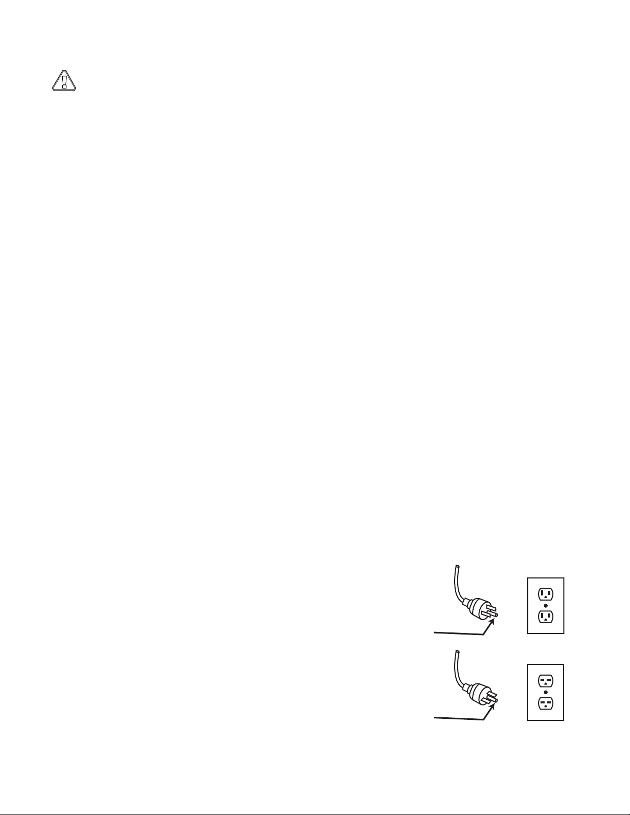
Grounding
Pin
Cover of Grounded
Outlet Box
Grounding
Pin
WARNING: When using X-arm™, basic precautions should always be followed, including:
• Read the entire users manual before attempting to use X-arm™.
• Keep everything and everyone away from X-arm™ while in motion. Do not contact moving parts.
• The user must observe the X-arm™ while it is in motion at all times until it is stopped by pressing on one of the
directional arrows on the remote control.
• Follow the installation instructions provided to correctly install X-arm™. To prevent injury, X-arm must be
securely attached to the wall in accordance with the installation instructions.
• X-arm™ restricts movement based upon the TV width set on the side controls of X-arm™. The TV width must
be set correctly before operating X-arm™.
• X-arm™ mounting bracket is intended for use only with the maximum weight of 180 pounds (81 kg). Use with
TVs heavier than 180 pounds (81 kg) may result in instability and cause injury.
• To reduce the risk of injury, close supervision is necessary when operating X-arm near children.
• Only use attachments recommended or sold by the manufacturer. Do not operate X-arm™ without all covers
and guards in place.
• Do not use outdoors.
• X-arm is designed to mount on vertical walls only. Do not mount X-arm on ceilings or non-vertical walls.
• To disconnect, turn all controls to the off (“O”) position, then remove plug from outlet.
• Do not unplug by pulling on cord. To unplug, grasp the plug, not the cord.
• Unplug from outlet when not in use and before servicing or cleaning.
• Do not operate X-arm with a damaged cord or plug, or after the appliance malfunctions or is dropped or
damaged in any manner. Return appliance to the nearest authorized service facility for examination, repair, or
electrical or mechanical adjustment.
• Connect to a properly grounded outlet only. See Grounding Instructions.
Grounding Instructions
This appliance must be grounded. In the event of malfunction or breakdown, grounding provides a path of least
resistance for electric current to reduce the risk of electric shock.
This appliance is equipped with a cord having an equipment-grounding conductor and a grounding plug. The plug
must be plugged into an appropriate outlet that is properly installed and grounded in accordance with all local codes
and ordinances.
DANGER – Improper connection of the equipment-grounding conductor can result in a risk of electric shock.
The conductor with insulation having an outer surface that is green with or without yellow stripes is the equipmentgrounding conductor. If repair or replacement of the cord or plug is necessary, do not connect the equipmentgrounding conductor to a live terminal.
Check with a qualied electrician or serviceman if the grounding
instructions are not completely understood, or if in doubt as to whether
the appliance is properly grounded. Do not modify the plug provided with
the appliance – if it will not t the outlet, have a proper outlet installed by
a qualied electrician.
This appliance is for use on a circuit having a nominal rating more than
120 V, 15 A and is for use on a circuit having a nominal rating of 120 V),
and is factory equipped with a specic electric cord and plug. No adapter
should be used with this appliance. If the appliance must be reconnected
for use on a different type of electric circuit, the reconnection should be
made by qualied service personnel; and after the reconnection, the
appliance should comply with all local codes and ordinances.
2 www.closystems.com
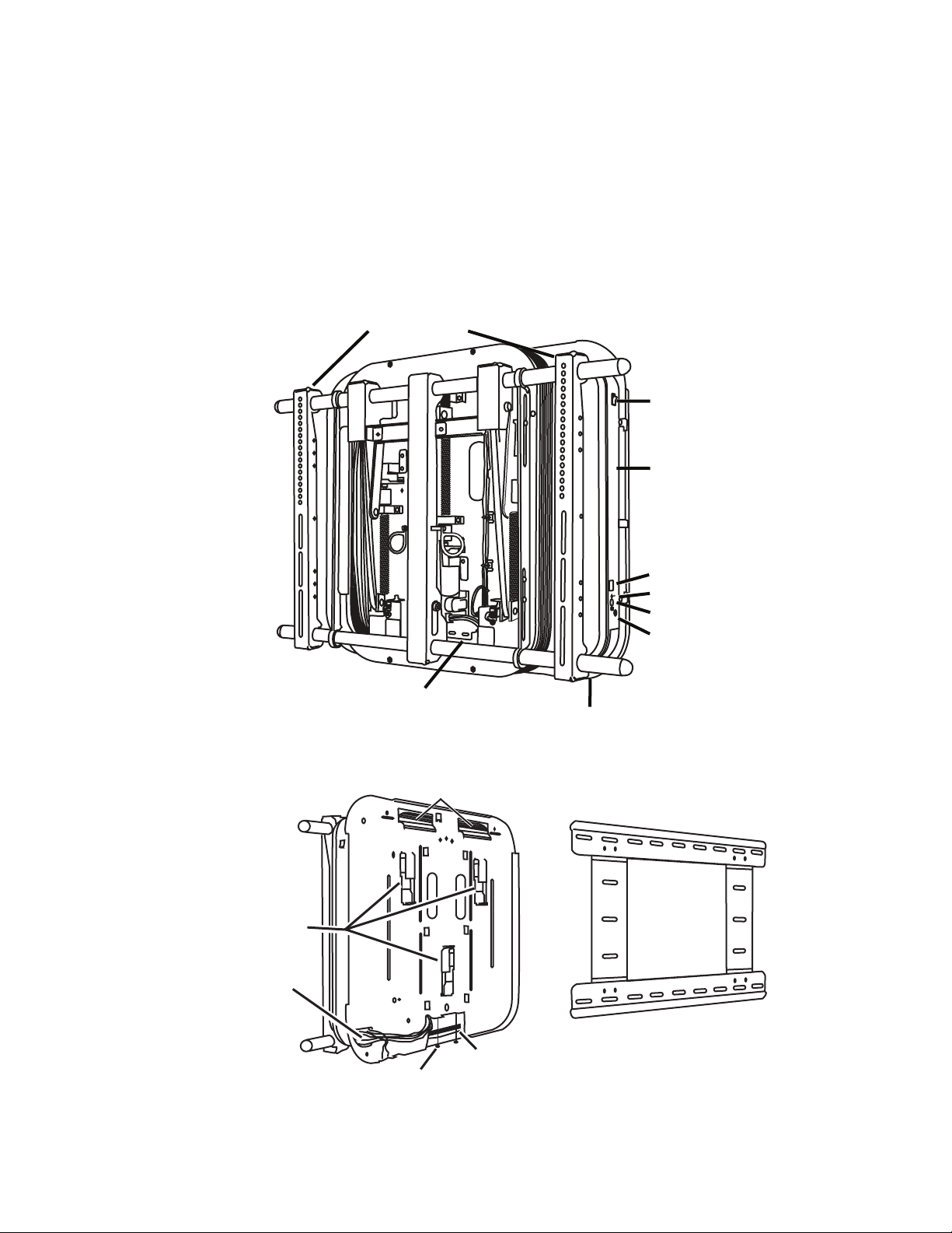
X-arm™ Overview
Se
t
TV Mounting
Brackets
Power Switch
Control Box
LED Display
Selector Button
Set Button
IR Receiver Socket
Power Cord Socket
Cord Channel
Hanging Hooks
Motors
Cable
Access Hole
Security
Screws
Wall Plate
(Ships attached to X-arm back)
RS 232 Cable Channel
(X700 CS & CB only)
X-arm™ mount is a motorized mount for most at-panel TVs from 40” to 63” (101,6 to 160 cm),
weighing up to 180 pounds (81 kg). X-arm™ allows a viewer to adjust the viewing angle of the
TV with the touch of a remote control button. In the retracted position, the TV is 4.6” (11,68 cm)
from the wall. Activating X-arm™ smoothly extends the TV away from the wall about 12” (30,48
cm) allowing you to swivel the TV from side to side and tilt it up and down. As X-arm™ mount
extends the TV from the wall, a bellows extends with the TV to cover the X-arm™ actuators and
all of TV cables within the bellows. This gives X-arm™ a clean look.
X-arm™ (front)
X-arm™ (back)
www.closystems.com 3
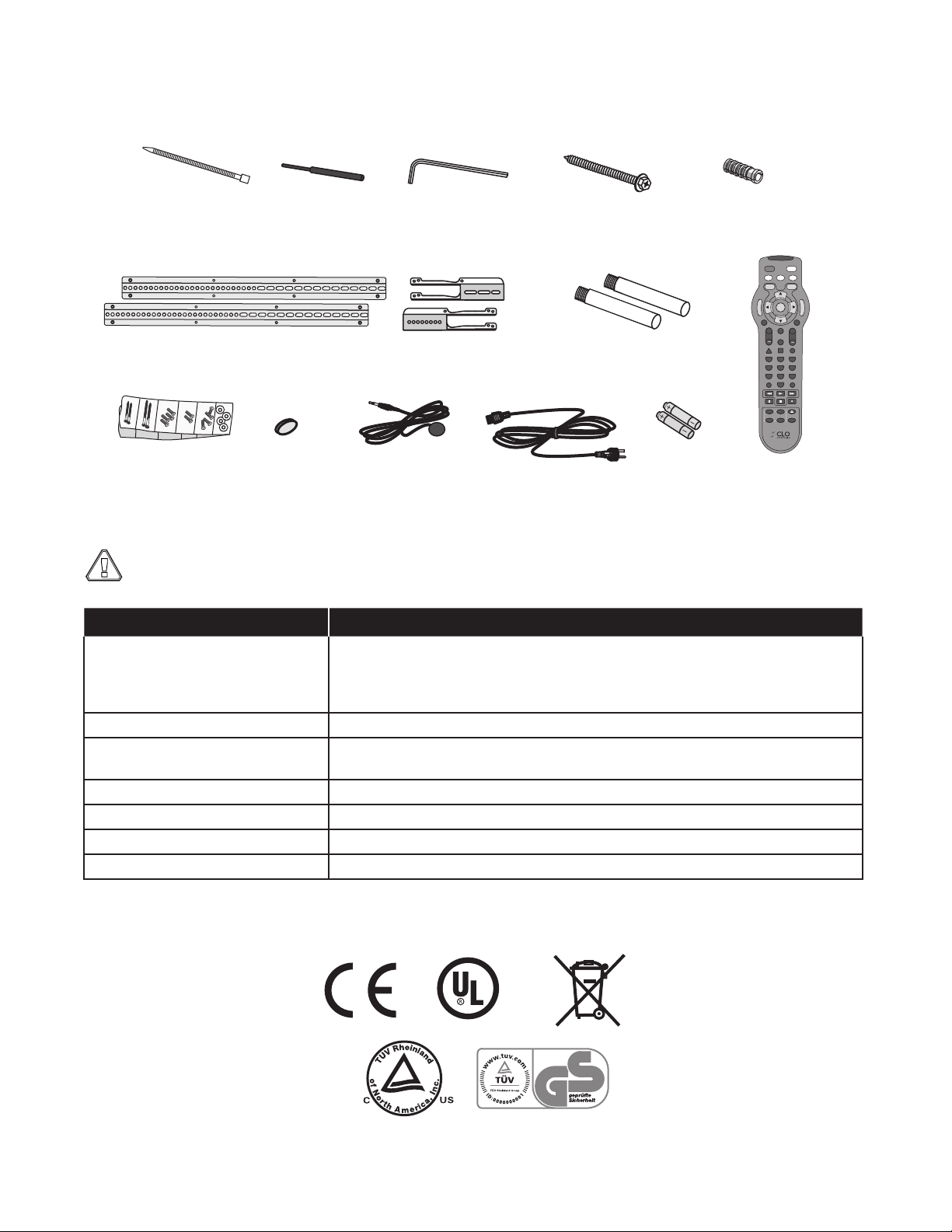
X-arm™ packaging includes:
!
Screen Size
Selection Pointer
Hex Wrench
(for safety clips)
Black 2-1/2” (63 mm)
Wall Screws (X6)
TV Mounting
Hardware
Zip Tie
Fasteners (X10)
Cement
Anchors (X6)
IR Receiver
(for remote control)
Cross Plates
(Optional)
Bar Extenders
(Optional)
Size AA
Batteries
IR Receiver
Velcro Tab Power Cord
Remote Control
Bracket Extensions
(Optional)
PIP
SWAP
POSITION
FREEZE
OPEN/CLOSE
SLEEP
P1
P3
+
VOL
+
CH
POWER
TV
IN OUT
MOUNT
VCR
DVD
CBL
SET
P
R
E
S
E
T
P
R
E
S
E
T
MENU
EXIT
MUTE
FAV
INFO TV/VCR GUIDE
LAST ENTER
1 2 3
4 5 6
7 8 9
0
P2
P4
C US
X-arm™ Specications
Caution: X-arm™ mount is intended for use only with the maximum weight and TV widths
indicated. Use with products heavier than the maximum weight or larger than the TV widths
indicated may result in instability and cause injury.
Specication Value
Maximum Tilt/Swivel Ranges
based upon TV outside width
TV Sizes Accomodated 40” - 61” (102 - 155 cm) TV outside width must be < 63” (160 cm).
Overall Mount Size 31 1/2” (w) x 22 3/4” (h) x 4 1/2” (d)
Maximum Weight Limit 180 lbs. (81 kg)
Minimum Extension from Wall 4.6” + TV (11,68 cm + TV)
Maximum Extension from Wall 12” + TV (30,48 + TV)
Weight of X-arm 60 lbs. (29,50 kg)
Certications & Marks
4 www.closystems.com
40” - 44.9” (102 - 113 cm): 7° up, 20° down, 28° left, right (56° total)
45” - 48.9” (114 - 123 cm): 7° up, 20° down, 26° left, right (52° total)
49” - 55.9” (124 - 140 cm): 7° up, 20° down, 23° left, right (46° total)
56” - 63.0” (142 - 160 cm): 7° up, 20° down, 19° left, right (38° total)
80 cm (w) x 57,80 cm (h) x 11,43 cm (d)
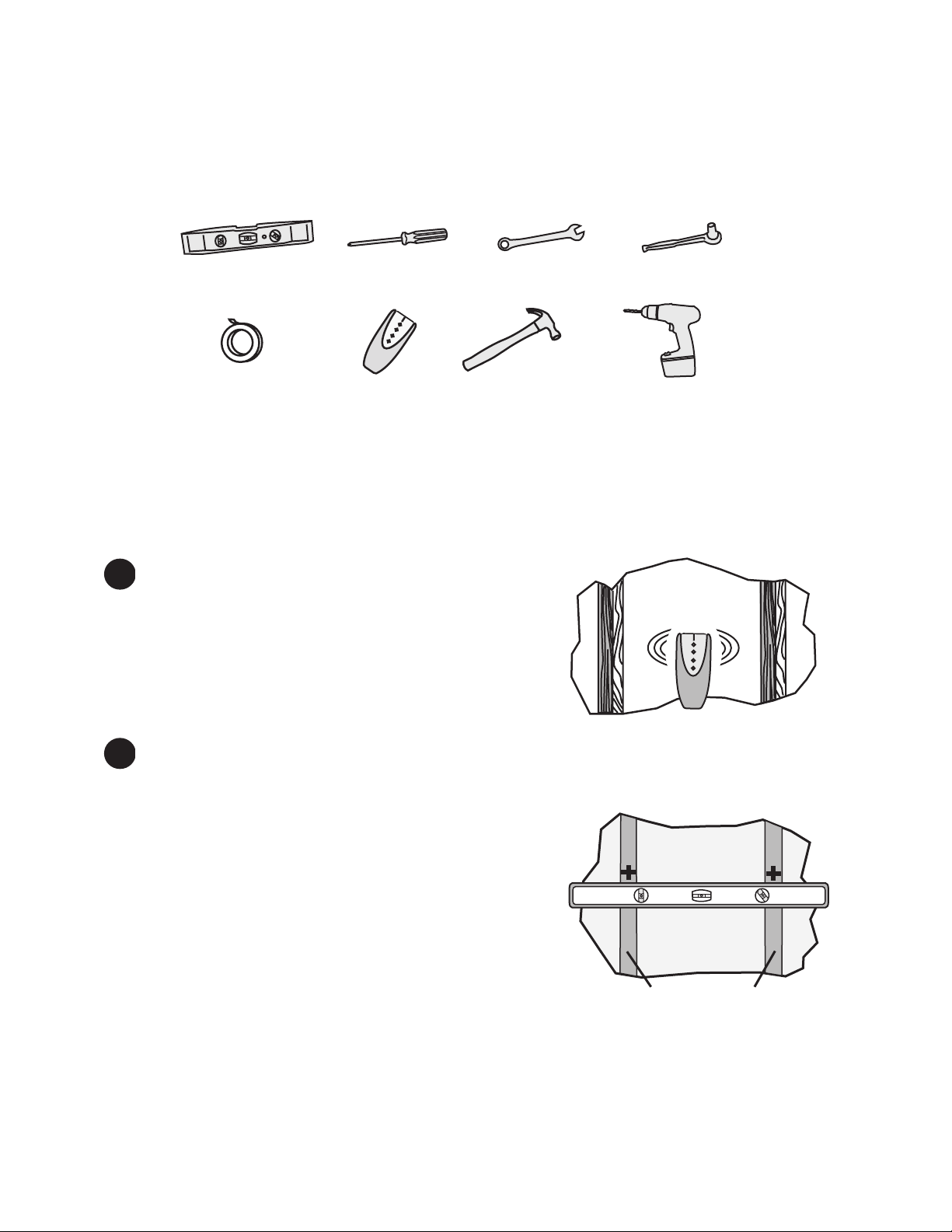
Installing X-arm™
2”x 4” (51 x 102 mm)
Wood Studs
Level Philips screw
driver
Adhesive tape
3/8” (9.5 mm)
wrench
Socket wrench
(optional)
Stud finder Hammer
Drill with 1/8” (3mm) bit
(Wood stud wall)
Masonry bit (Concrete wall)
For concrete wall installation, go to the “Concrete Wall Installation” section. For wood stud wall
installation continue below.
Tools Needed
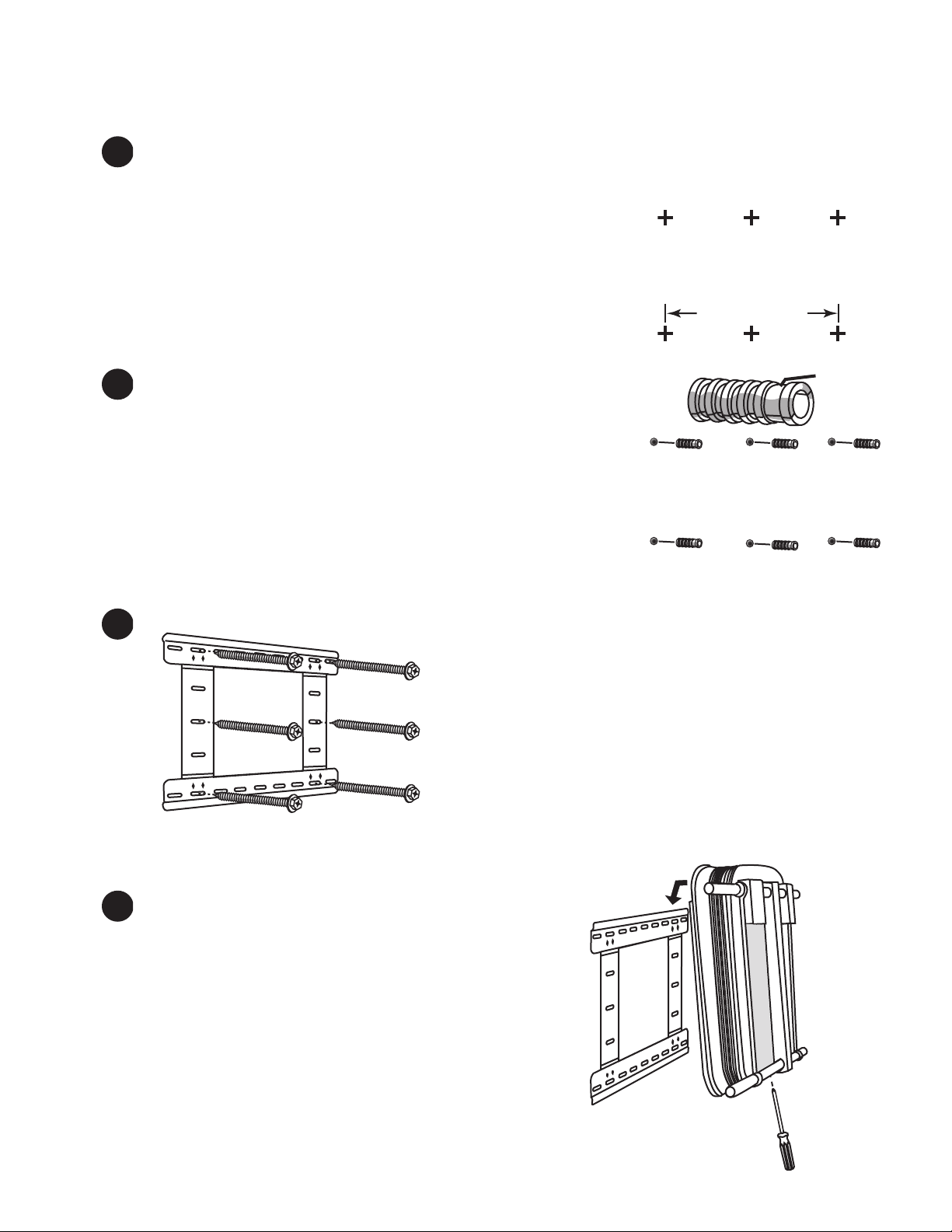
Wood Stud Wall Installation
1. Locate wall studs
1-1.Using a stud nder, locate two wooden studs no
more than 17” (43,18 cm) apart, center to center.
1-2. Mark the stud centers on the wall.
To avoid property damage or injury, the mount must
attach to at least two 2” x 4” (51 x 102 mm) wood
studs.
2. Drill mounting holes
2-1. Remove the wall plate from the back of the X-arm™. First loosen the 2 security screws
at the bottom, then lift the wall plate off the X-arm™.
2-2. Hold the wall plate up to the wall so that the
mounting holes line up with studs.
2-3. Level the wall plate.
2-4. Mark the 6 places where the wall plate holes line
up with the wall studs.
2-5. Remove the wall plate, then drill 6 holes with a
1/8” (3mm) drill bit, 2-1/2” (6,35 cm) deep at the
locations drawn from step 2-4.
www.closystems.com 5
Concrete Wall Installation
16” (406.4 mm)
hinge
4.1
4.3
1. Mark anchor locations
1-1. Remove the wall plate from the back of the X-arm™. First loosen the 2 security screws at
the bottom, then lift the wall plate off the X-arm™.
1-2. Hold the wall plate up to the wall where you want the X-arm™
located.
1-3. Level the wall plate.
1-4. Mark the wall in 6 places as shown. Holes should be as far
apart as possible.
2. Install six screw anchors
2-1. Using a 1/2” (13 mm) masonry drill bit, drill 6 holes 2-1/2”
(6,35 cm) deep at the locations drawn in step 1-4.
2-2. Install the 6 anchors as shown with the hinged end facing
toward you.
Both Wood Stud & Concrete Wall Installation
3. Hang the wall plate
4. Hang X-arm™ on the wall
4-1. Hang the X-arm™ on the top edge of the wall plate.
4-2. If needed, slide X-arm™ on the wall plate about 1.5”
(3,81 cm) in either direction to center it in the room.
4-3. Using a philips screw driver, tighten the 2 security
screws on the bottom of the X-arm™.
3-1. Secure the wall plate to the wall using all
six of the provided black 2-1/2” (6,35 cm) lag
bolts.
6 www.closystems.com
Se
t
Power
switch
Do not use.
(incorrect)
Use this width.
(correct)
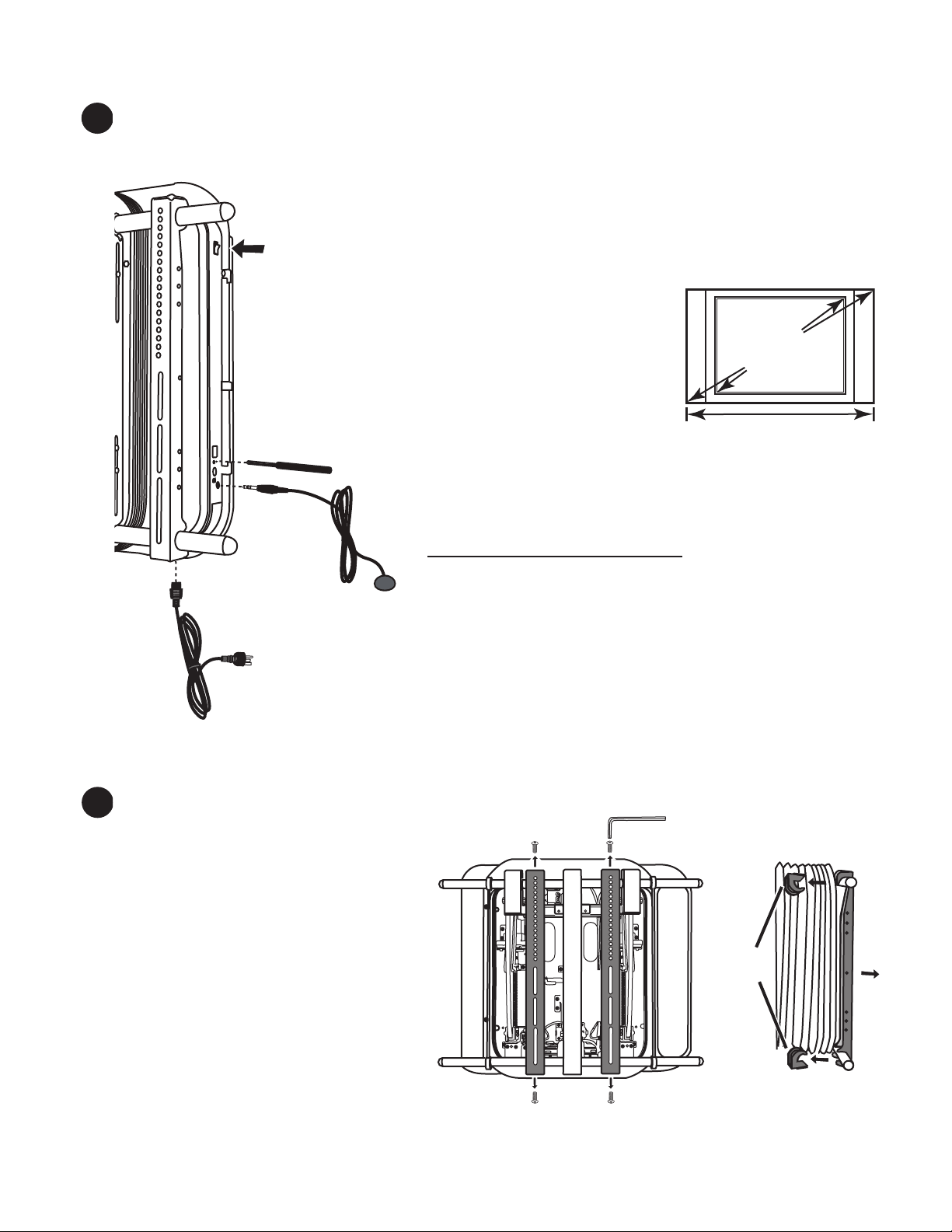
5. Set the X-arm™ TV width
Safety
Clips
It is important to set the correct TV width on X-arm™ to avoid injury or property damage. The Xarm™ restricts movement based upon the TV width that is set.
5-1. Attach the power cord and connect the X-arm™ to a grounded power
outlet. The X-arm™ power cord has a grounding conductor grounding
plug. The plug must be plugged into an appropriate outlet with 3 prongs
that is properly installed and grounded in accordance with all local
codes and ordinances. See the front of this manual for more grounding
instructions.
5-2. Press the power switch to ON (1).
IMPORTANT: Do not operate the X-arm by
using the remote control at this time.
5-3. Measure the total width of the TV including any
side speakers that may be attached to the TV.
Do not use the TV manufacturer’s screen size,
which is measured diagonally, to set the TV
width on X-arm™.
5-4. Insert the provided plastic pointer into the Selector hole, and
press the button until the TV width code corresponds to the
outside width of your TV as indicated in the table below.
Code TV Outside Width
C1 40” - 44.9” (102 - 113 cm)
C2 45” - 48.9” (114 - 123 cm)
C3 49” - 55.9” (124 - 140 cm)
C4 56” - 63.0” (142 - 160 cm)
5-5. Hold the black rubber Set button, below the selector hole, until the TV
width code stops blinking.
5-6. Attach the IR receiver.
5-7. Optional (X700CS & CB Models only): To control X-arm™ with home
automation through the RJ11/RS232 port, see page 22 for instructions.
6. Remove the TV Mounting Brackets
6-1. Extend X-arm™ straight out from the
wall by pressing the MOUNT button
and then the OUT button on the
remote once while aiming at the IR
Receiver.
6-2. Remove the hex screws from the
ends of the TV Mounting Brackets
with the provided hex wrench.
6-3. Pull the Safety Clips from the backs
of the TV Mounting Brackets, and
then remove the TV Mounting
Brackets.
6-4. Save all the removed pieces.
www.closystems.com 7
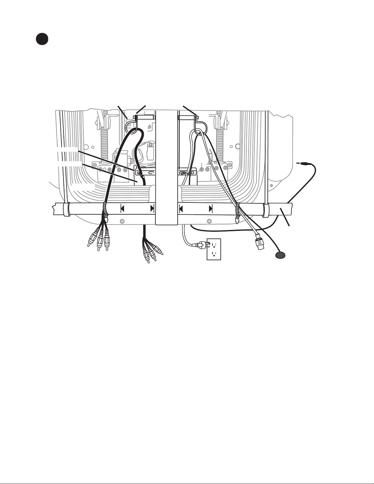
7. Route the Cables and IR Receiver
AV Cables
to TV
AV Cables from
Component
TV Power Outlet
(outside bellows)
Power
to TV
IR Reciever Eye
IR Reciever
Plug
Cable Loops
Bellows
No Cable
2” (5 cm)
No Cable
2” (5cm)
Cable Bar
Bottom Cross Bar
Cable Hole
Cable Tie Anchor
X-arm is designed to hide cables and the TV power cord by passing them through the bellows to
the wall. Use the cable-separating features built into X-arm™ to keep the power and AV cables
separated to minimize electrical interference and binding as X-arm™ moves.
If the TV power outlet is located outside the bellows of X-arm™, follow the directions below.
If the power outlet for your TV and X-arm™ is located inside the bellows, go to page 9.
8 www.closystems.com
7-1. Run A/V cables over the bottom cross bar, through a cable loop and down through the
cable hole in the back of the X-arm.
7-2. Run the TV power cord on the other side the same way.
7-3. Unplug the IR Receiver and run the plug end up over the bottom cross bar, through a
cable hook and out the cable hole. Plug the IR Receiver back into the side of X-arm™.
7-4. The AV, power cord, and IR Receiver cords must be long enough to connect equipment,
but not so long that they get caught in X-arm™ parts. Test this by tilting up, down, and
side to side.
7-5. Using the provided zip ties, fasten all cables to the Cable Bar located near the Cable Hole.
7-6. Using the provided zip ties, fasten the cables to the Bottom Cross Bar so that they pass
over the cross bar. The cables should be at least 2” (5 cm) from the center beam. Cut off
the excess zip tie ends.
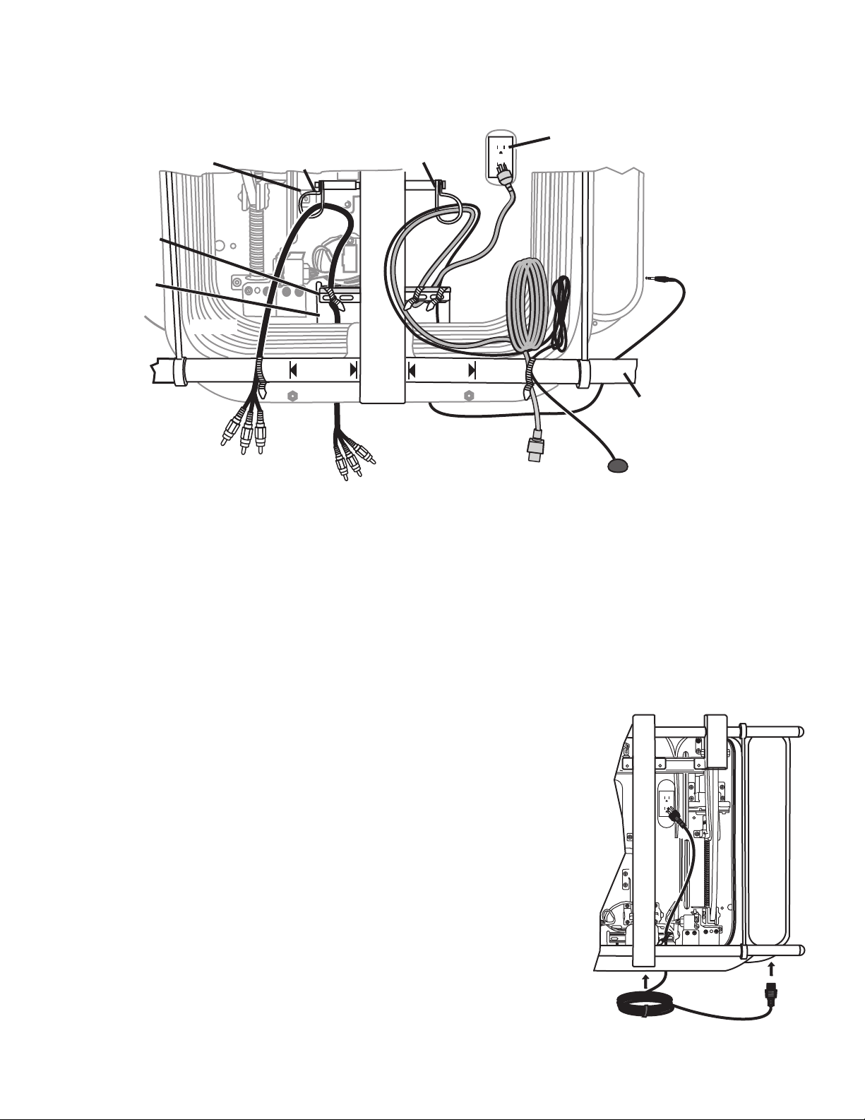
If the power outlet for TV and X-arm™ is located inside the bellows of X-arm™, follow these
AV Cables
to TV
AV Cables from
Component
TV Power
Cord
IR Reciever
Plug
AV Cable Loop
Bellows
No Cable
2” (5 cm)
No Cable
2” (5 cm)
Cable Bar
Cable Hole
Bottom Cross Bar
IR Receiver Eye
Center
Beam
TV Power outlet
inside belows.
Cable Tie Anchor
TV Power &
IR Receiver Hook
X-arm power cord
directions.
7-1. Run A/V cables on the left side going over the bottom cross bar, through a cable loop and down
through the cable hole in the back of the X-arm.
7-2. Run the TV power cord over the bottom cross bar, through the right cable loop, under the cable
bar at the back, and up toward the electrical outlet. Secure the power cord to the cable bar
using a zip tie.
7-3. Run the IR receiver cord over the bottom cross bar, through the right cable loop, through the
bellows and down through the cord hole, plugging it into the side of the X-arm™ control box.
7-4. Coil up the excess TV power cord and IR Receiver cord and put a zip tie around them.
7-5. Plug the X-arm™ power cord into X-arm™, run the cord up
through the cable hole and plug it in, gathering the excess with
a cable tie. Place the cord into the space near the cable bar as
shown to the right. Fasten it to the cable bar with another zip tie.
7-6. The AV, power cord, and IR Receiver cords must be long enough
to connect equipment, but not so long that they get caught in Xarm™ parts. Test this by tilting up, down, and side to side.
7-7. Fasten all cables to the cable bar at the back of X-arm™ using
the provided zip ties.
7-8. Fasten the cables to the bottom cross bar so that they are at least
2” (5 cm) from the center beam. Cut off the excess zip tie.
www.closystems.com 9
 Loading...