

Page 1
USER MANUAL
DM65
Manual Flush/Tilt Combo Mount
1
D1_1.11.11.indd 1 1/14/11 2:41 PM
Page 2

!
CAUTION
When using this mounting system, basic precautions should be followed, including:
•Follow the entire installation/user’s manual and the important safety instructions
before attempting to install or use this mounting system.
•Manufacturer is not liable for damage or injury caused by incorrect mounting,
assembly, or use.
•This mount fits most screens from 42” to 65”.
•This mount system supports a maximum weight of 150 lbs (68 kg) and maximum
screen size of 65”.
•Attaching a TV that is heavier than the maximum size and weight specified may
result in instability, and possible personal injury.
•Only attach this mount system on vertical walls as instructed in this manual.
•If you have any doubts about the ability of the wall to support the TV and mount-
ing system, contact a qualified contractor.
•This product contains small items that could be a choking hazard if swallowed.
•Keep these items away from children.
•For indoor use only.
Engineered and Designed in the USA, and Assembled in China.
PATENT PENDING
2
D1_1.11.11.indd 2-3 1/14/11 2:41 PM
3
Page 3
1/2”
(12.7mm)
7/32”
(5.5mm)
Before Installation
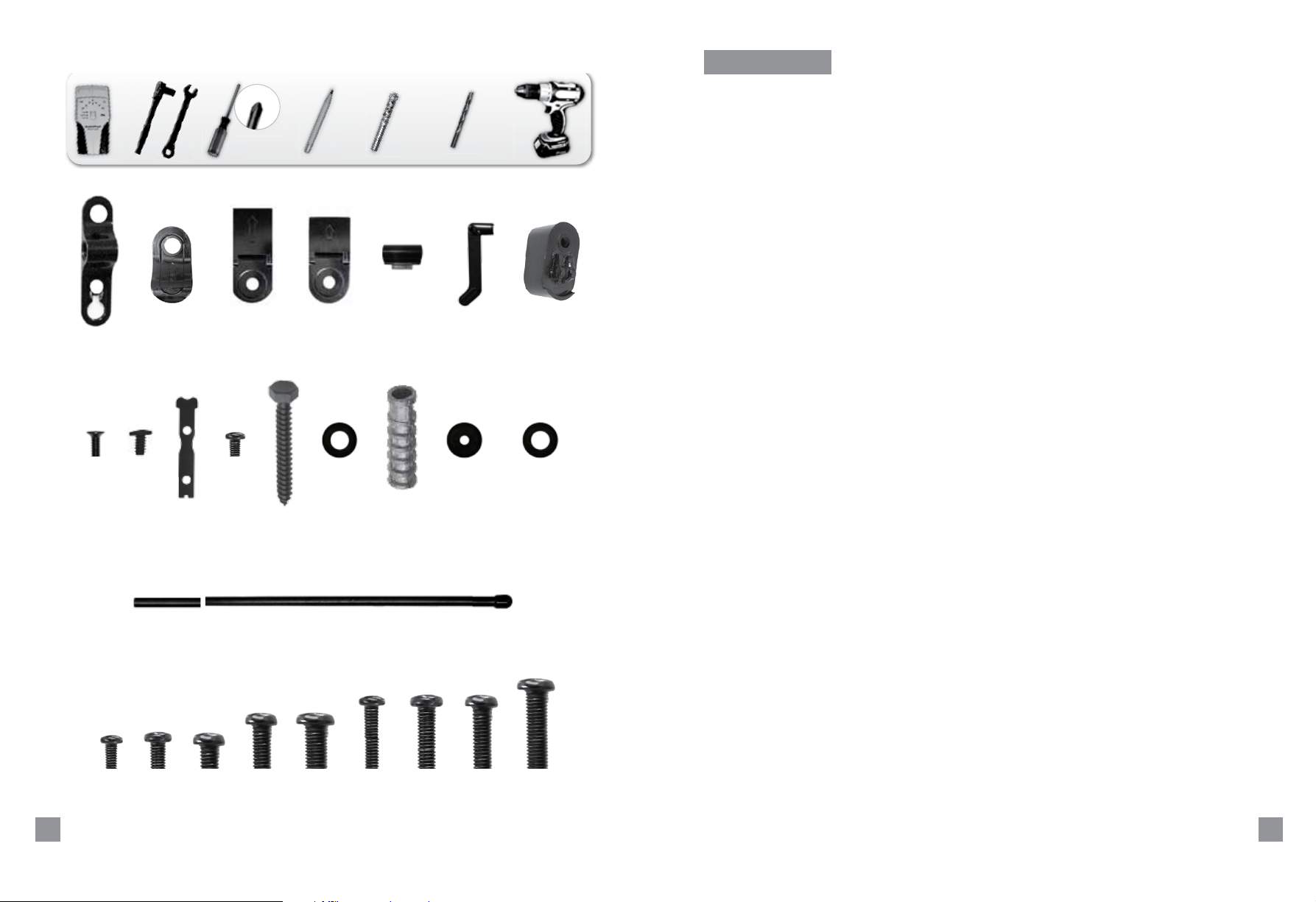
Before starting assembly, verify that all the parts are included and undamaged. If any
parts are missing or damaged, do not return the item to your dealer; contact customer
service number listed on the back cover. Never use damaged parts.
[A] x 3 [B] x 2
[H] x 1
[I] x 1
[J1] x 1
[O] x 1 [P] x 1
[J2] x 1
[K1] x 6
[D] x 1[C] x 1 [F] x 1 [G] x 2
[K2] x 6
[E] x 1
[L] x 6
[M] x 6
[N] x 6
[M4 - 15]
4
D1_1.11.11.indd 4-5 1/14/11 2:41 PM
[Q] x 4
[M5 - 15]
[R] x 4
[M6 - 15]
[S] x 4
[M6 - 20]
[T] x 4
[M8 - 20]
[U] x 4
[M4 - 44]
[V] x 2
[M5 - 44]
[W] x 2
[M6 - 44]
[X] x 2
[M8 - 48]
[Y] x 2
5
Page 4
1.0
2” x 4”
[A]
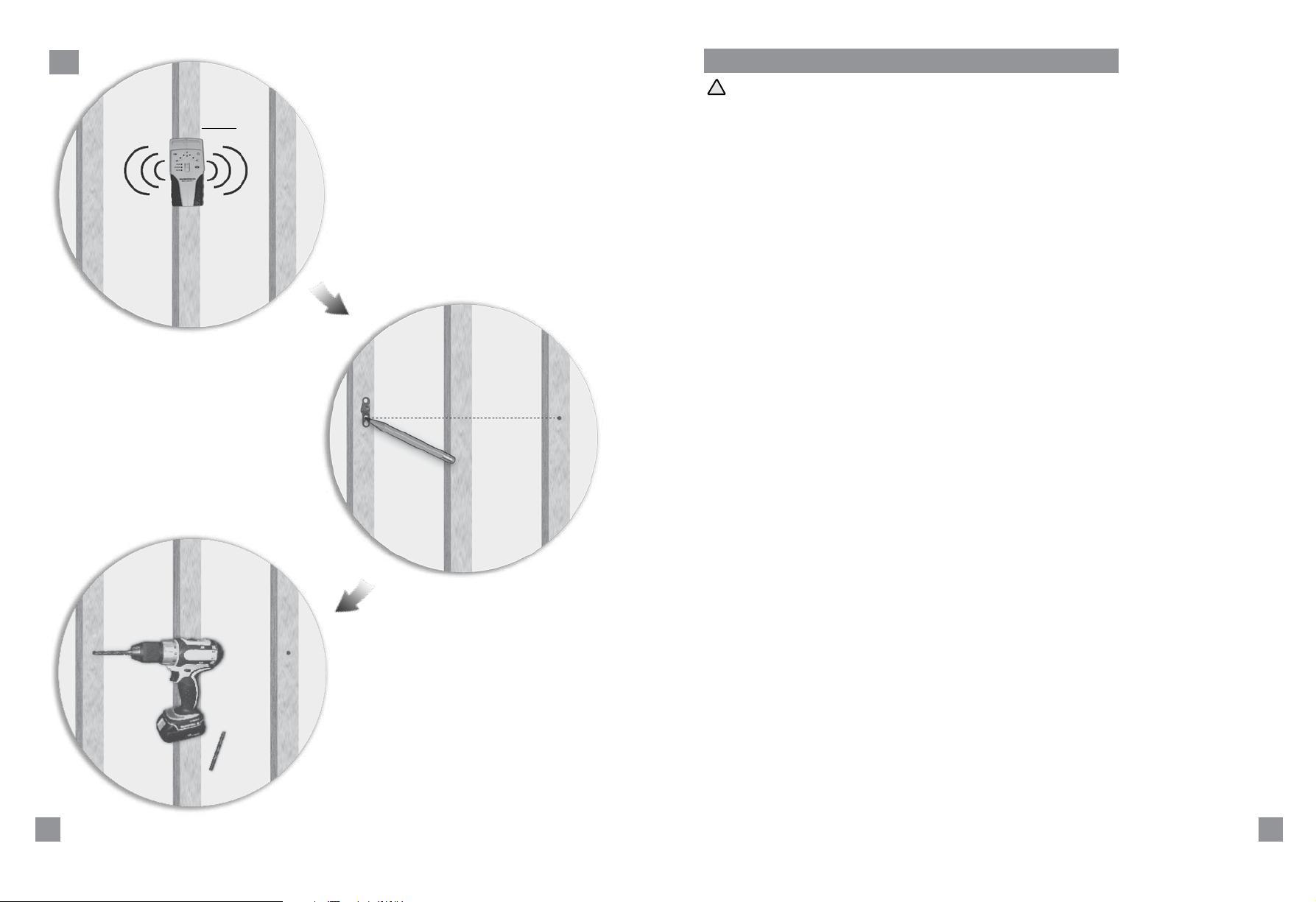
1.0 Mounting to a Wall with Wooden Studs
!
CAUTION: The wall covering (drywall, lath, plaster, and the like) may not exceed
0.5” (12.7 mm) thickness. A minimum of 6 lag bolts [K1] are required to secure the
mount.
TV’s 42”- 65
7/32”
(5.5mm)
6
D1_1.11.11.indd 6-7 1/14/11 2:41 PM
7
Page 5
2.0
[A]
[K2]
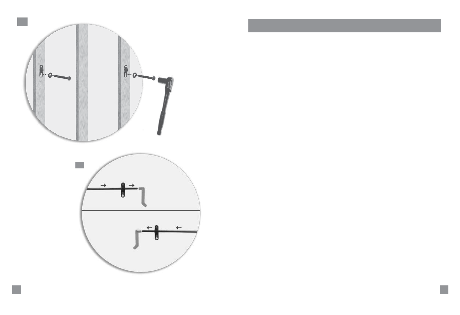
2.0 Secure the two lag bolts [K1, K2] through the elongated holes to the wood studs, but do
not tighten them completely.
2.1 Choose the placement of the handle. Right: insert the shaft from left to right. Left:
insert the shaft from right to left.
[K1]
2.1
8
D1_1.11.11.indd 8-9 1/14/11 2:41 PM
9
Page 6
3.0
[A]
TV’s 42”- 65
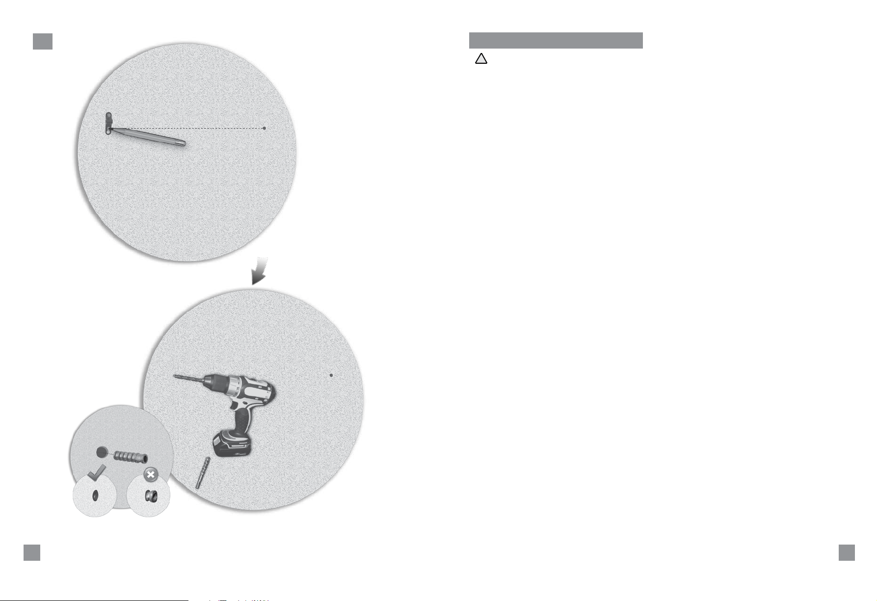
3.0 Mounting to Solid Concrete Walls
!
CAUTION: Concrete anchors must be flush with the concrete surface. A minimum
of 6 lag bolts are required to secure the mount.
[L]
1/2”
(12.7mm)
10
D1_1.11.11.indd 10-11 1/14/11 2:41 PM
11
Page 7
4.0
[A]
[K2]
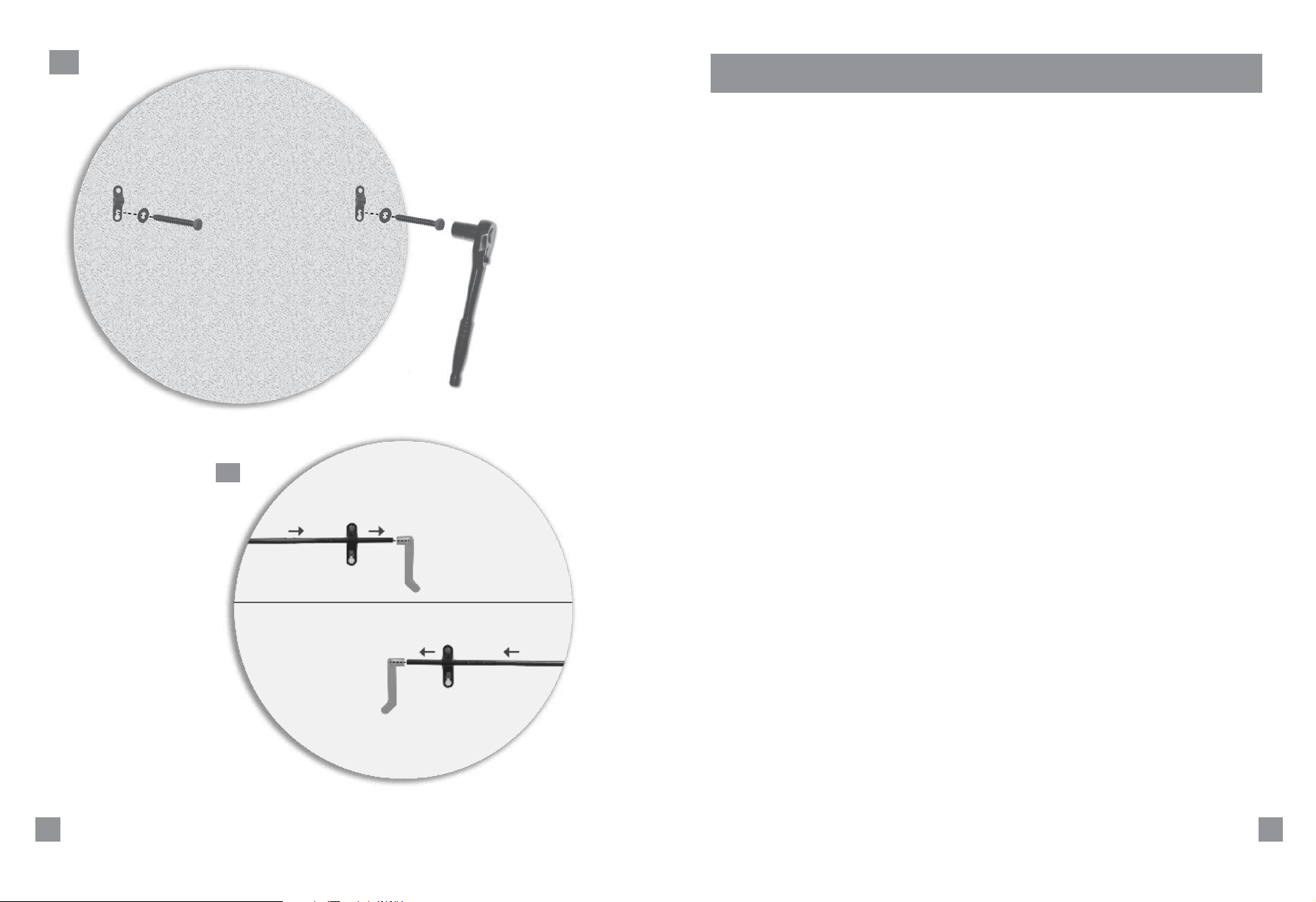
4.0 Secure the two lag bolts [K1, K2] through the elongated holes to the concrete wall, but
do not tighten them completely.
4.1 Choose the placement of the handle. Right: insert the shaft from left to right. Left:
insert the shaft from right to left.
[K1]
4.1
12
D1_1.11.11.indd 12-13 1/14/11 2:41 PM
13
Page 8
5.0
[A] [A] [A]
5.1
[P]
[E]
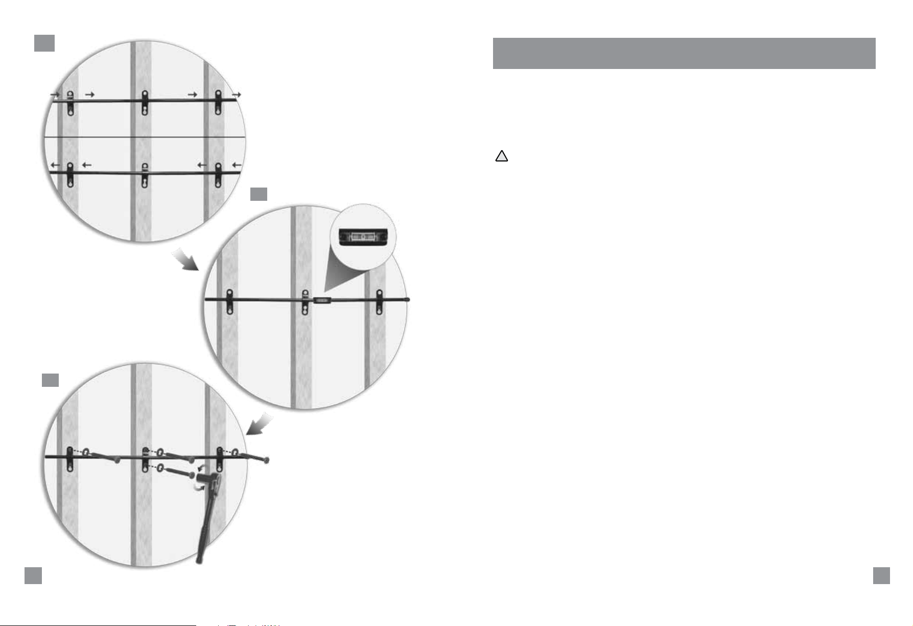
5.0 Place the third wall bracket [A] between the two outer wall brackets and insert the shaft
through all three wall brackets.
5.1 Snap on the leveler [E] and rotate the leveler facing forward. Level the shaft [P] until it is
leveled.
5.2 Mark and predrill rest of the holes and insert rest of the lag bolts [K1, K2]. Secure all lag
bolts tightly.
!
Caution: Make sure to remove and save leveler before hanging the TV.
5.2
14
D1_1.11.11.indd 14-15 1/14/11 2:41 PM
15
Page 9
6.0
6.1
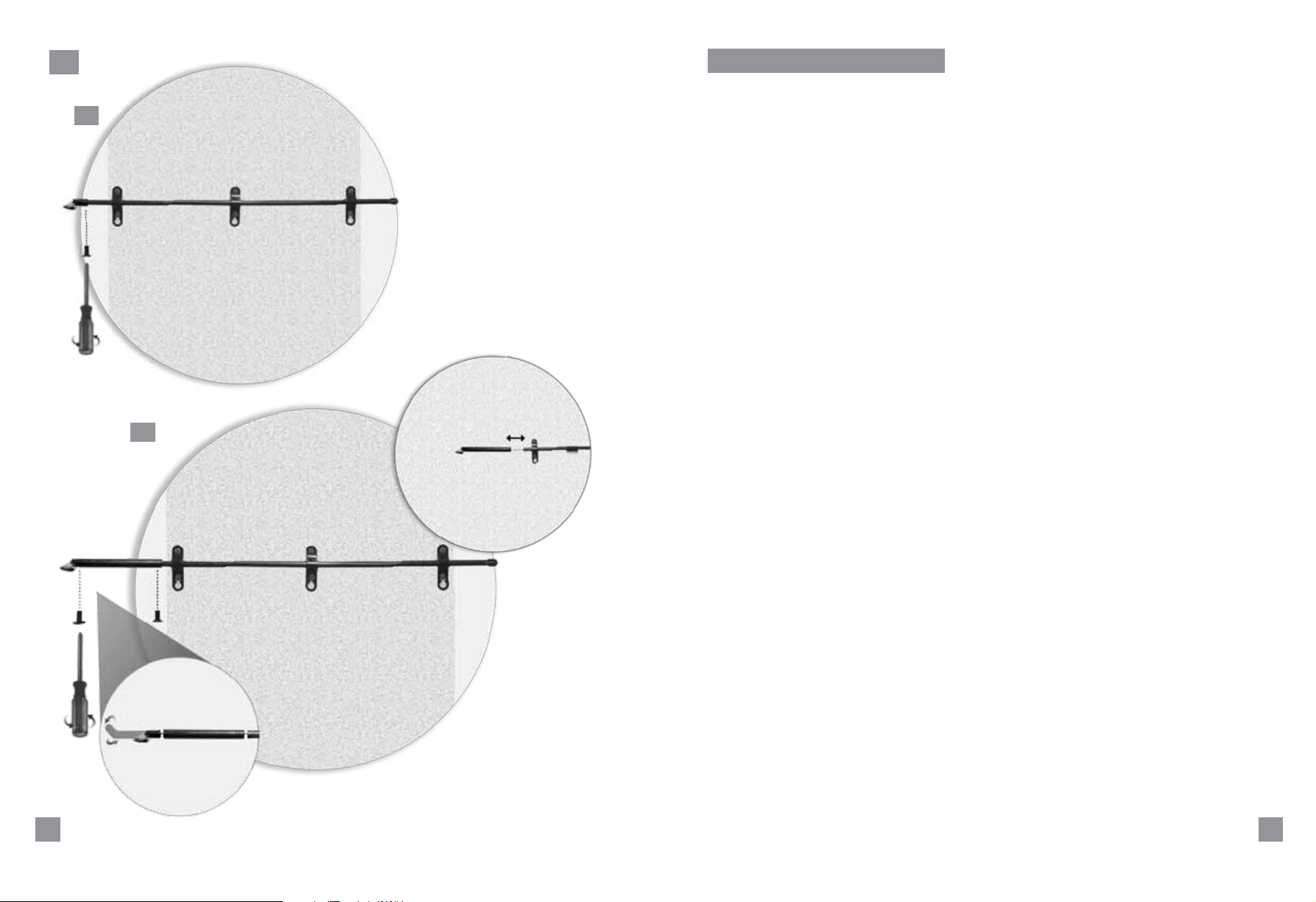
6.0 Secure the Handle to the Shaft.
6.1 Attach the handle [F] on the opposite end of the end cap. Use the screw [H] on the
bottom to tighten.
6.2. *Insert the extension bar [O] if the TV size is between 46”- 65” using the screws
[H and I].
[H]
[F]
[O]
6.2
[P]
[O]
TVs 46”- 65”.
[I] [H]
16
D1_1.11.11.indd 16-17 1/14/11 2:41 PM
17
Page 10
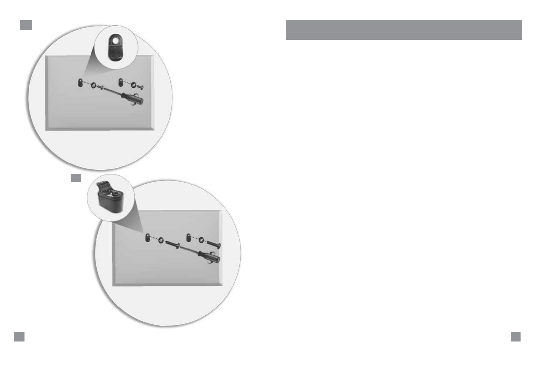
7.0
7.0 Install the two mounting hooks [B] on the top two holes on the back of the TV
securing them tightly.
7.1
[G]
[B]
[B]
[M, N]
[Q, R, S, T, U]
7.1 Optional: To achieve approximately 9˚ of fixed tilt, combine mounting hooks [B]
and spacers [G] securing them tightly.
[M, N]
[V, W, X, Y]
18
D1_1.11.11.indd 18-19 1/14/11 2:41 PM
19
Page 11
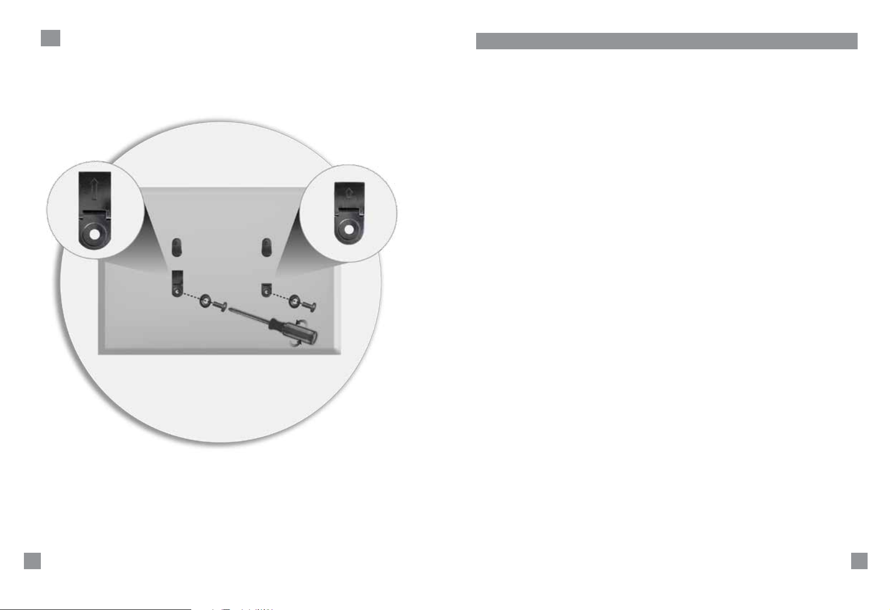
8.0
[C] [D]
[M, N]]
[Q, R, S, T, U]
8.0 Install the two kick stands [C, D] on the bottom two holes on the back of the TV.
20
D1_1.11.11.indd 20-21 1/14/11 2:41 PM
21
Page 12
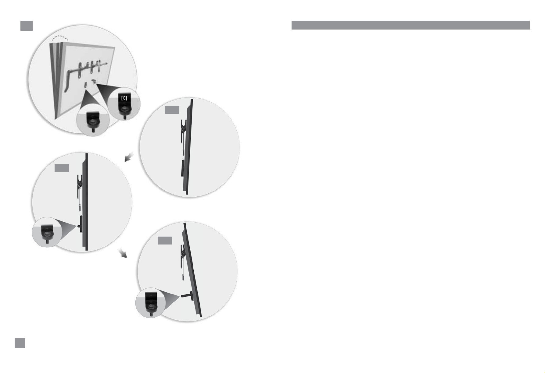
9.0
9.0 Kick Stand Operation without Spacers.
9.1With both kickstands [C,D] in the closed position, the TV will tilt about 3˚.
9.2 Use kickstand [D] to achieve the flush position.
9.3 Use kickstand [C] to tilt up.
[D]
9.2
[E]
0˚
[D]
[C]
9.3
9.1
3˚
0˚
[B]
[C]
22
D1_1.11.11.indd 22-23 1/14/11 2:41 PM
Page 13
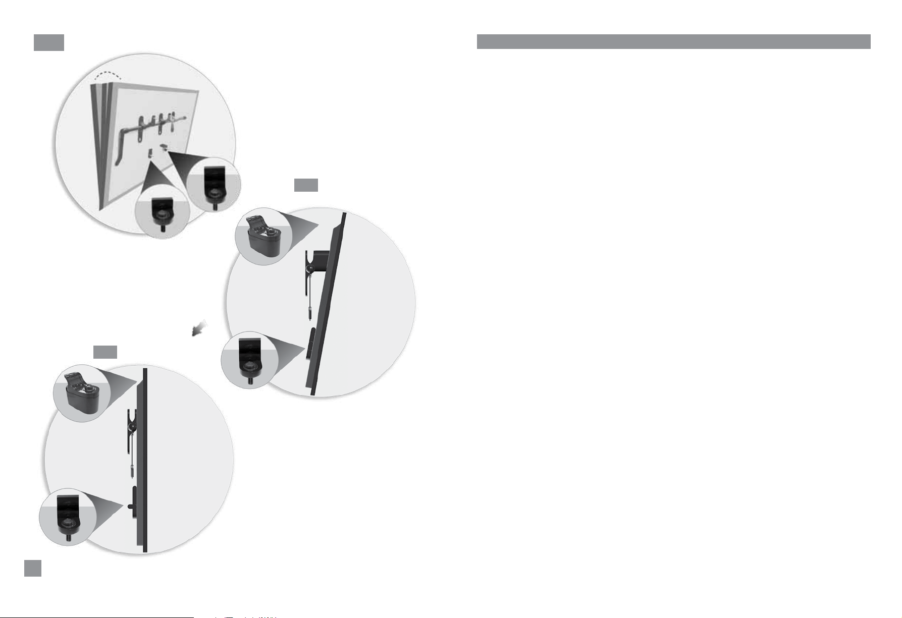
10.0
10.0 Kick Stand Operation with Spacers
10.1 With spacers, the TV will tilt about 9˚.
10.2 Use kickstand [C, D] to adjust to lesser tilt angle.
[A]
[B]
10.2
[E]
[C]
10.1
[D]
[A]
9˚
[B]
0˚
[D]
0˚
[D]
24
D1_1.11.11.indd 24-25 1/14/11 2:41 PM
Page 14
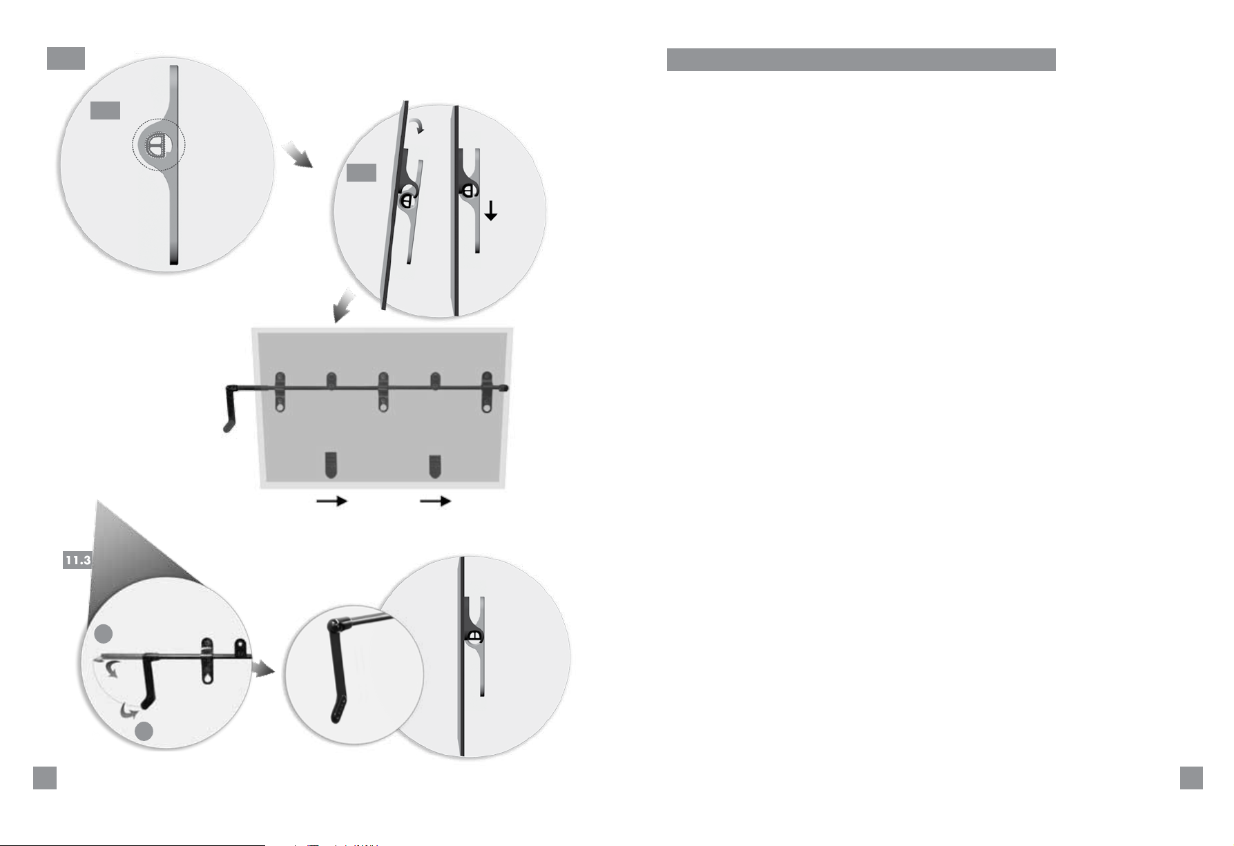
11.0
11.0 Hang the TV Screen.
11.1 Ensure that the shaft is in an unlock position as shown in 11.1.
11.1
11.2 Lift and lower the TV so that the two hooks [B] rest on the shaft.
11.3
11.2
[B]
11.3 Slide the TV, so that the handle [F] is accessible. Use the handle to rotate the
shaft to the lock position shown in 11.3.
1
[F]
2
26
D1_1.11.11.indd 26-27 1/14/11 2:42 PM
27
Page 15
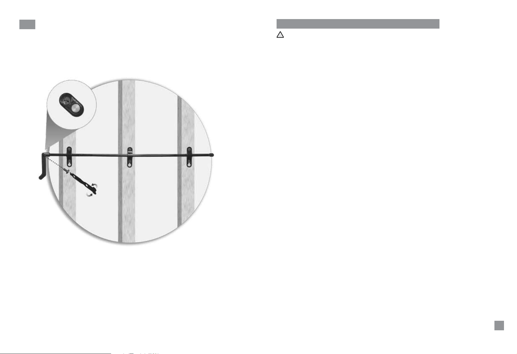
12.0
[F]
[J2]
[J1]
12.0 Anti-theft lock (Mandatory)
Insert the J-screw [J2] using the driver [J1] through the handle [F].
!
29
D1_1.11.11.indd 28-29 1/14/11 2:42 PM
Page 16

Limited Warranty
CLO Systems (“CLO”) warrants its products, under normal use, to be free of defects in material
and workmanship for the product’s Warranty Period as specified below (“Warranty):
•Lifetimeformanualmountsandstands;and
•One(1)yearforallmotorizedand/orautomatedmountsandstands.
The Warranty period commences on the original purchase date, and it extends only to the
original purchaser purchased from an authorized dealer, distributor, or retailer. The Warranty is
automatically void if the product:
•is modified in any way, improperly installed, or the product is supporting a monitor that
is heavier than the stated weight capacity of the product;
•is used outdoors;
•is damaged due to misuse, abuse, negligence, accident or shipping;
•has been repackaged, resold or refurbished;
•has been purchased from an unauthorized party; and
•has been reinstalled in a different location or with different monitor.
To the maximum extent permitted by applicable law, CLO disclaims any other warranties,
express or implied, including warranties of fitness for a particular purpose and warranties of
merchantability. CLO will not be liable for any damages whatsoever arising out of the use or
inability to use its products, even if CLO has been advised of the possibility of such damages. To
the maximum extent permitted by applicable law, CLO disclaims any responsibility for incidental
or consequential damages.
For warranty claims made during the Warranty Period, CLO will replace any defective product
part free of charge. Should a part on your CLO product fail, call CLO at 877-4CLO-SYS (877
425-6797) to make a warranty claim. We will discuss the problem with you and once we confirm
the product is under Warranty, we will ship replacement parts to you. This Limited Warranty does
not cover the costs of removing and replacing defective parts from your CLO product. Therefore,
should the repair require a technician, CLO is not responsible for any labor charges.
Disclaimer
CLO Systems, LLC makes no claim that the information contained herein covers all details,
conditions, or variations. Nor does it provide for every possible contingency in connection with
the installation or use of this mounting system. The information contained in this document is
subject change without notice or obligation of any kind. CLO Systems makes no representation
of warranty, expressed or implied, regarding the information contained herein. CLO Systems
assumes no responsibility of accuracy, completeness or sufficiency of the information contained
in this document.
31
D1_1.11.11.indd 30-31 1/14/11 2:42 PM
 Loading...