


WallWizard X700CB User Manual
X-arm Control Box Replacement
IR Receiver
Soccket
Set
Selector
Screen Size
POWER
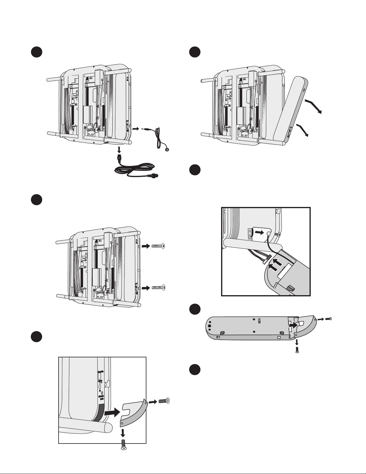
Unplug the power cord and IR Receiver.
1.
POWER
Screen Size
Selector
Set
IR Receiver
Soccket
Remove the screws from the side of the
2.
control box and save them.
Slide the control box away from the X-arm.
4.
Unplug both connectors, making sure to
5.
release the locks under the connectors.
Remove the grounding wire connecting the
control box to the X-arm frame.
POWER
Remove the screws from the control box
3.
cover and remove it.
POWER
Screen Size
Selector
Set
IR Receiver
Soccket
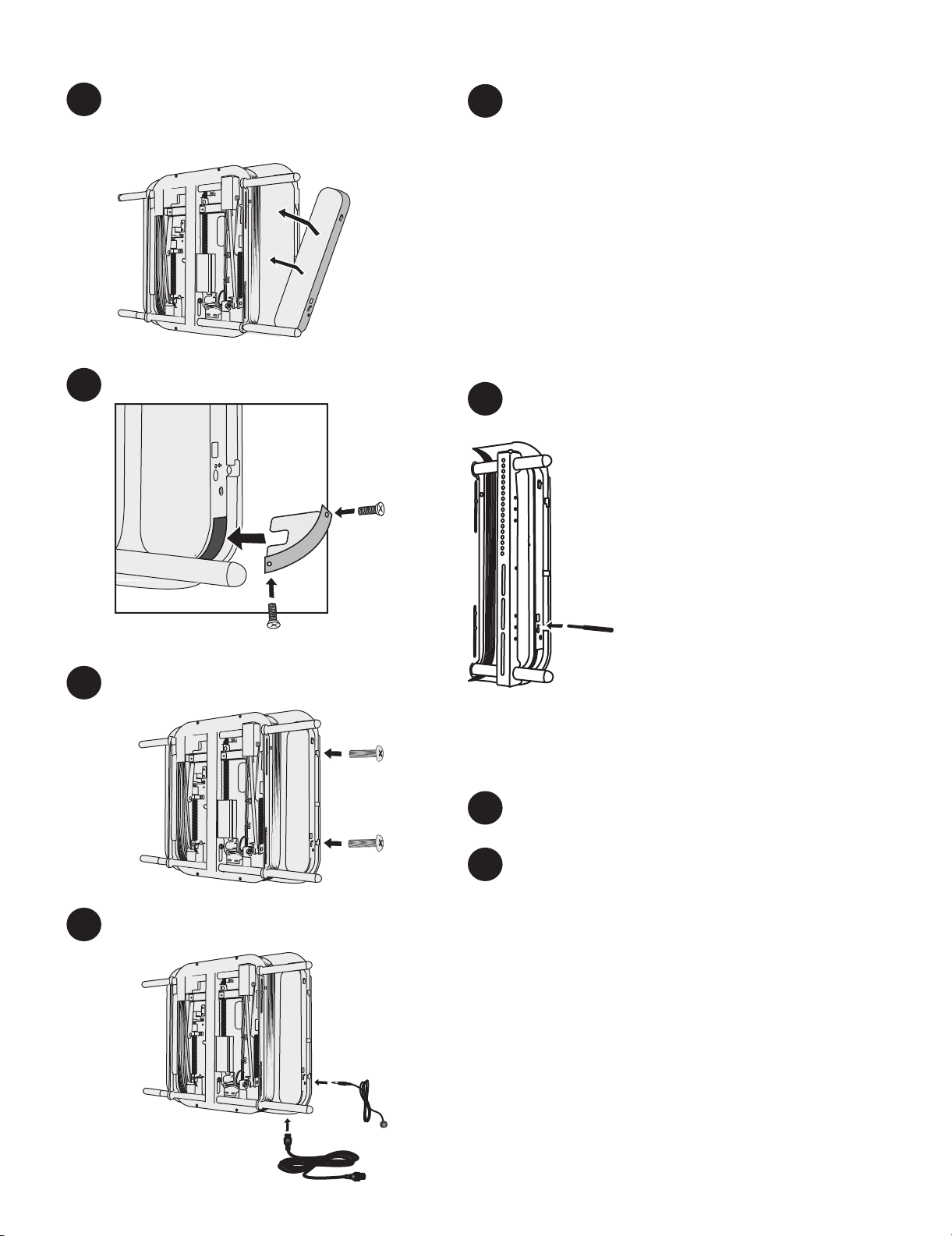
Remove the cover from the new control box.
6.
Reverse the action performed in step 5 by
7.
routing the grounding wire from the new control
box to the X-arm, attaching it with the screw
from step 5.
Route the wire bundles from the X-arm through
the wire hole, and attach them to the connectors
of the same color on the control box. The
connectors ends only fit one way so do not force
them.
X-arm Control Box Replacement (Continued)
IR Rec
eiv
er
S
o
cc
ket
S
et
S
elec
t
or
Scr
e
e
n
Si
z
e
P
O
WER
S
et
IR Rec
eiver
S
o
cc
k
et
S
et
S
el
ec
t
or
S
c
r
een
S
i
z
e
PO
W
ER
IR Rec
ei
v
er
S
occket
S
et
S
elector
Screen S
i
z
e
PO
WE
R
IR
Re
c
e
i
v
er
S
o
c
c
k
et
Se
t
S
e
lec
to
r
Scr
e
en
S
i
z
e
Line up the three hooks on the control box
8.
with the slots in the X-arm.
Slide the control box onto the X-arm.
POWER
Attach the control box cover.
9.
Screen Size
or
Select
Set
iver
IR Rece
Soccket
Secure the control box to the X-arm with the
10.
screws from the old control box.
PO
W
ER
If X-arm is in the home position against the wall,
12.
continue to step 13. If not, follow these steps to get
X-arm into the home position:
12-1. Press the POWER switch to ON (1).
12-2. Insert the provided plastic pointer
into the Selector hole, and press
the button until the LED reads “t”.
12.3. Use the remote control to straighten
X-arm so that it is parallel with the
wall. Once parallel with the wall,
press the “Set” button on the control
box for three seconds. X-arm
should return to the home position.
Set the TV size code (see below).
13.
13-1. Press the POWER switch to ON (1).
13-2. Measure the total width of the TV
POW
ER
including any side speakers that
may be attached to the TV.
13.3. Insert the provided plastic pointer
into the Selector hole, and press
the button until the TV width code
corresponds to the outside width of
e
Siz
Screen
or
ect
Sel
Set
er
eceiv
IR R
cket
Soc
your TV (see below).
Code TV Outside Width
C1 40” - 44.9” (102 - 113 cm)
C2 45” - 48.9” (114 - 123 cm)
C3 49” - 55.9” (124 - 140 cm)
C4 56” - 61.0” (141 - 155 cm)
13.4. Hold the Set button until the LED
display stops blinking.
ze
i
n S
ee
cr
S
tor
ec
l
Se
Set
eiver
IR Rec
t
Soccke
Attach the power cord and IR Receiver.
11.
Plug the X-arm into a grounded power outlet.
POW
ER
ize
een S
Scr
ctor
e
l
Se
t
Se
eiver
IR Rec
et
k
c
Soc
14.
15.
R1: 4-3-07
Mount the TV as shown in your manual.
Recalibrate the X-arm to your TV.
To avoid damage, X-arm must be in the home
position before you calibrate it.
15-1. Switch off the main power on the side
of X-arm.
15-2. Hold down the Set button on the
control box while switching on the
power. Continue holding down the Set
button for 5 seconds until the display
reads CT.
15-3. Stand back while X-arm™ calibrates,
moving in - out, left - right and up down.
15-4. X-arm™ is done calibrating when it
goes back to the home position against
the wall.