

Waldorf Pulse User Manual
S Y N T H E S I Z E R
User’s Manual
Pulse • Pulse Plus

➤
Vielen Dank für den Kauf dieses Waldorf Produktes. Es zeichnet sich durch
Zuverlässigkeit und Langlebigkeit aus. Dennoch können Material- oder
Verarbeitungsfehler nicht völlig ausgeschlossen werden. Daher bieten wir
Ihnen eine verlängerte Garantie. Damit Garantieleistungen in Kraft treten,
müssen Kaufrechnung und Garantiekarte vollständig ausgefüllt innerhalb
von 14 Tagen zurückgesandt werden. Diese Garantie erstreckt sich auf alle
Defekte in Material und Verarbeitung für den Zeitraum von 1 Jahr ab Kauf
des Produktes. Während der Garantiezeit ersetzt oder repariert Waldorf
Electronics das durch Waldorf Electronics oder ein autorisiertes Service
Zentrum als defekt befundene Produkt, ohne dem Kunden Material- oder
Arbeitsaufwand in Rechnung zu stellen.
Um die Garantie in Anspruch zu nehmen, muß sich der Kunde zunächst
telefonisch mit dem zuständigen Vertrieb in Verbindung setzen. Produkte,
die ohne vorherige Absprache eingesandt werden, können nicht kostenfrei
ausgetauscht bzw. repariert werden.
Das Produkt muß frei und versichert in Originalverpackung eingesandt
werden. Detaillierte Fehlerbeschreibungen sind beizufügen. Unfrei und/oder
nicht originalverpackt eingesandte Produkte gehen ungeöffnet zurück.
Waldorf Electronics behält sich vor, das eingesandte Produkt auf den neusten
Stand der Technik zu bringen, wenn dies erforderlich sein sollte.
Diese Garantie deckt keine Defekte ab, die durch unsachgemäße
Behandlung oder Eingriffe von unautorisierten Personen verursacht wurden
und ist beschränkt auf die Behebung von Defekten, die während der
normalen Nutzung durch Material- oder Verarbeitungsfehler aufgetreten
sind.
Thank you for choosing this Waldorf product. It is a dependable device and
is designed to last. However, the potential for defects in material or
workmanship cannot be eradicated completely. This is why we provide an
extended warranty for you.
To ensure your unit has full warranty coverage, mail the receipt and the fully
completed warranty card back within 14 days of purchase.
This warranty covers all defects in material and workmanship for a period of
one year from the date of original purchase. During this time, Waldorf
Electronics will repair or replace the product without charge for materials or
labor, provided the product was first inspected and found faulty by Waldorf
Electronics or an authorized service center. You must first contact your dealer
or distributor by telephone. Products that were mailed without prior
agreement cannot be exchanged or repaired free of charge.
The unit must be insured and sent prepared in its original package. Please
include a detailed description of the defect. Products that were not send
prepared or in the original package will be returned unopened.
Waldorf Electronics reserves the right to upgrade the unit with the latest
technological advances if necessary.
This warranty does not cover defects due to abuse, operation under other
than specified conditions, or repair by unauthorized persons. The warranty
covers only those malfunctions caused by material or workmanship defects
that occur during normal operation.
Bitte schicken Sie die Garantiekarte vollständig ausgefüllt zusammen mit
einer Kopie der Kaufrechnung zurück, um die Produktgarantie in Anspruch
nehmen zu können.
Please fill out this warranty card completely, include a copy of the purchase
receipt and send the two items to us in order to ensure the warranty is valid.
Garantiekarte / Warranty Card
Produktgarantie / Product Warranty
✁
Produkt / Product:
Sonderausstattungen / Custom features:
Sonstige verwendete Geräte / Other used equipment:
Seriennummer / Serial number: Kaufdatum / Purchase date:
Name Ihres Händlers / Name of your dealer:
Ort Ihres Händlers / City of your dealer:
➤
➤
➤
Waldorf Electronics
Support Department
Neustraße 9-12
53498 Waldorf
Germany
Straße / Street:
PLZ, Wohnort / ZIP Code, City:
Land / Country:
Telefon / Telephone:
Telefax / Facsimile:
Name / Name:
S Y N T H E S I Z E R
+
S Y N T H E S I Z E R

4
Produktunterstützung / Product Support
✁
Wenn Sie Fragen zu Ihrem Waldorf Produkt haben, gibt es vier
Möglichkeiten, uns zu kontaktieren:
If you have any questions about your Waldorf product, feel free to contact us
via one of the four options listed below.
Schicken Sie uns eine E-Mail. Das ist der mit
Abstand effizienteste und schnellste Weg, uns zu
erreichen. Ihre Fragen können sofort an die
richtige Stelle weitergeleitet und innerhalb
kürzester Zeit beantwortet werden.
Senden Sie uns ein Telefax. Fast so schnell wie EMail, allerdings für Sie und uns weniger
komfortabel.
Schicken Sie uns einen Brief. Etwas langsamer,
dafür jedoch genauso zuverlässig wie ein
Telefax.
Und wenn es ganz dringend ist, rufen Sie uns an.
Wir versuchen, Ihre Fragen möglichst sofort zu
beantworten.
Send us an e-mail message. This is the most
efficient and fastest way to contact us. Your
questions will be forwarded immediately to the
resident expert and you will quickly receive an
answer.
Send us a fax. This is as fast as e-mail, but not
quite as comfortable for you and us.
Send us a letter. It will take a bit longer, but it is
just as dependable as a fax.
If you’re in big hurry, call us, we’ll try to answer
your questions right away.
info@waldorf-gmbh.de
+49-(0)2636-7935
+49-(0)2636-80563
Waldorf Electronics
Neustraße 9-12
53498 Waldorf, Germany
4
3
3
2
2
1
1

User’s Manual Pulse • PulsePlus
5
1. Contents
1.1 Table of Contents
2. Control Features and Connections . . . . . . . . . . . . . . . . . . . . . . . . . . . . . . . . 7
2.1 Front Panel . . . . . . . . . . . . . . . . . . . . . . . . . . . . . . . . . . . . . . . . . . . . . 7
2.2 Rear Panel . . . . . . . . . . . . . . . . . . . . . . . . . . . . . . . . . . . . . . . . . . . . . 7
3. Foreword . . . . . . . . . . . . . . . . . . . . . . . . . . . . . . . . . . . . . . . . . . . . . . . . . . . 8
4. Introduction . . . . . . . . . . . . . . . . . . . . . . . . . . . . . . . . . . . . . . . . . . . . . . . . 9
4.1 Symbols . . . . . . . . . . . . . . . . . . . . . . . . . . . . . . . . . . . . . . . . . . . . . . . 9
4.2 Highlighted Control Features and Parameters . . . . . . . . . . . . . . . . . . . . 9
5. General Safety Guidelines . . . . . . . . . . . . . . . . . . . . . . . . . . . . . . . . . . . . . 10
5.1 Suitable Operating Conditions . . . . . . . . . . . . . . . . . . . . . . . . . . . . . . 10
5.2 Power Supply . . . . . . . . . . . . . . . . . . . . . . . . . . . . . . . . . . . . . . . . . . 10
5.3 Operation . . . . . . . . . . . . . . . . . . . . . . . . . . . . . . . . . . . . . . . . . . . . . 10
5.4 Maintenance . . . . . . . . . . . . . . . . . . . . . . . . . . . . . . . . . . . . . . . . . . . 11
5.5 Proper Use . . . . . . . . . . . . . . . . . . . . . . . . . . . . . . . . . . . . . . . . . . . . 11
6. Setup and Operation . . . . . . . . . . . . . . . . . . . . . . . . . . . . . . . . . . . . . . . . . 12
6.1 Inventory . . . . . . . . . . . . . . . . . . . . . . . . . . . . . . . . . . . . . . . . . . . . . 12
6.2 Setup . . . . . . . . . . . . . . . . . . . . . . . . . . . . . . . . . . . . . . . . . . . . . . . . 12
6.3 Connections . . . . . . . . . . . . . . . . . . . . . . . . . . . . . . . . . . . . . . . . . . . 12
7. Operation . . . . . . . . . . . . . . . . . . . . . . . . . . . . . . . . . . . . . . . . . . . . . . . . . 14
7.1 Powering Up . . . . . . . . . . . . . . . . . . . . . . . . . . . . . . . . . . . . . . . . . . . 14
7.2 Selecting Programs . . . . . . . . . . . . . . . . . . . . . . . . . . . . . . . . . . . . . . 14
Factory and User Programs . . . . . . . . . . . . . . . . . . . . . . . . . . . . . . . . 14
Random Program . . . . . . . . . . . . . . . . . . . . . . . . . . . . . . . . . . . . . . . 15
7.3 Editing Sound Parameters . . . . . . . . . . . . . . . . . . . . . . . . . . . . . . . . . . 15
7.4 The Store Function . . . . . . . . . . . . . . . . . . . . . . . . . . . . . . . . . . . . . . 17
7.5 The Compare Function . . . . . . . . . . . . . . . . . . . . . . . . . . . . . . . . . . . 18
7.6 Deleting Edits . . . . . . . . . . . . . . . . . . . . . . . . . . . . . . . . . . . . . . . . . . 18
7.7 Viewing Parameter Values . . . . . . . . . . . . . . . . . . . . . . . . . . . . . . . . . 18
8. Sound Parameters . . . . . . . . . . . . . . . . . . . . . . . . . . . . . . . . . . . . . . . . . . . 19
8.1 Overview of Functions . . . . . . . . . . . . . . . . . . . . . . . . . . . . . . . . . . . 19
8.2 Oscillators . . . . . . . . . . . . . . . . . . . . . . . . . . . . . . . . . . . . . . . . . . . . 20
Oscillator 1 . . . . . . . . . . . . . . . . . . . . . . . . . . . . . . . . . . . . . . . . . . . . 20
Oscillator 2 . . . . . . . . . . . . . . . . . . . . . . . . . . . . . . . . . . . . . . . . . . . . 21
Oscillator 3 . . . . . . . . . . . . . . . . . . . . . . . . . . . . . . . . . . . . . . . . . . . . 23
Noise Generator . . . . . . . . . . . . . . . . . . . . . . . . . . . . . . . . . . . . . . . . 23
8.3 Mixer . . . . . . . . . . . . . . . . . . . . . . . . . . . . . . . . . . . . . . . . . . . . . . . . 24
8.4 Low-frequency Oscillators (LFOs) . . . . . . . . . . . . . . . . . . . . . . . . . . . . 25
LFO 1 . . . . . . . . . . . . . . . . . . . . . . . . . . . . . . . . . . . . . . . . . . . . . . . . 25
LFO 2 . . . . . . . . . . . . . . . . . . . . . . . . . . . . . . . . . . . . . . . . . . . . . . . . 27
8.5 Envelopes . . . . . . . . . . . . . . . . . . . . . . . . . . . . . . . . . . . . . . . . . . . . . 28
Envelope 1 . . . . . . . . . . . . . . . . . . . . . . . . . . . . . . . . . . . . . . . . . . . . 28
Envelope 2 . . . . . . . . . . . . . . . . . . . . . . . . . . . . . . . . . . . . . . . . . . . . 29
8.6 Modulations . . . . . . . . . . . . . . . . . . . . . . . . . . . . . . . . . . . . . . . . . . . 30
Modulation Matrix . . . . . . . . . . . . . . . . . . . . . . . . . . . . . . . . . . . . . . 30
Routing a Modulation Source to CV 2 Out . . . . . . . . . . . . . . . . . . . . . 34
Pitch Modulation . . . . . . . . . . . . . . . . . . . . . . . . . . . . . . . . . . . . . . . 35
Pitchbend . . . . . . . . . . . . . . . . . . . . . . . . . . . . . . . . . . . . . . . . . . . . . 35
Portamento . . . . . . . . . . . . . . . . . . . . . . . . . . . . . . . . . . . . . . . . . . . . 35
8.7 Filter . . . . . . . . . . . . . . . . . . . . . . . . . . . . . . . . . . . . . . . . . . . . . . . . . 36
8.8 VCA . . . . . . . . . . . . . . . . . . . . . . . . . . . . . . . . . . . . . . . . . . . . . . . . . 37
8.9 Global Parameters . . . . . . . . . . . . . . . . . . . . . . . . . . . . . . . . . . . . . . . 38
9. MIDI Control . . . . . . . . . . . . . . . . . . . . . . . . . . . . . . . . . . . . . . . . . . . . . . 39
9.1 Calling Programs via Program Change . . . . . . . . . . . . . . . . . . . . . . . . 39
9.2 Influencing Sounds via Control Change Messages . . . . . . . . . . . . . . . . 39
Controller as Modulation Sources . . . . . . . . . . . . . . . . . . . . . . . . . . . 39

6
User’s Manual Pulse • PulsePlus
Changing Sound Parameters . . . . . . . . . . . . . . . . . . . . . . . . . . . . . . . . 39
9.3 Pitchbending . . . . . . . . . . . . . . . . . . . . . . . . . . . . . . . . . . . . . . . . . . . 39
9.4 Aftertouch as a Modulation Source . . . . . . . . . . . . . . . . . . . . . . . . . . . 40
9.5 System Exclusive Data Transmission . . . . . . . . . . . . . . . . . . . . . . . . . . 40
Sending System Exclusive Data . . . . . . . . . . . . . . . . . . . . . . . . . . . . . 40
Receiving System Exclusive Data . . . . . . . . . . . . . . . . . . . . . . . . . . . . 40
9.6 Controller Dump . . . . . . . . . . . . . . . . . . . . . . . . . . . . . . . . . . . . . . . . 41
9.7 Panic Function . . . . . . . . . . . . . . . . . . . . . . . . . . . . . . . . . . . . . . . . . 41
9.8 Special Features . . . . . . . . . . . . . . . . . . . . . . . . . . . . . . . . . . . . . . . . 41
10. The Arpeggiator . . . . . . . . . . . . . . . . . . . . . . . . . . . . . . . . . . . . . . . . . . . . . 42
10.1 Arpeggiator Synchronization via MIDI Clock . . . . . . . . . . . . . . . . . . . 45
10.2 The Hold Mode . . . . . . . . . . . . . . . . . . . . . . . . . . . . . . . . . . . . . . . . . 45
11. Additional Functions of the Pulse Plus . . . . . . . . . . . . . . . . . . . . . . . . . . . . 46
11.1 Connections . . . . . . . . . . . . . . . . . . . . . . . . . . . . . . . . . . . . . . . . . . . . . . . 46
11.2 Audio Input . . . . . . . . . . . . . . . . . . . . . . . . . . . . . . . . . . . . . . . . . . . . . . . . 46
11.3 CV/Gate Interface . . . . . . . . . . . . . . . . . . . . . . . . . . . . . . . . . . . . . . . . . . . . 47
11.4 Global Parameters . . . . . . . . . . . . . . . . . . . . . . . . . . . . . . . . . . . . . . . . . . . 48
MIDI/System Parameters . . . . . . . . . . . . . . . . . . . . . . . . . . . . . . . . . . 48
CV/Gate Parameters . . . . . . . . . . . . . . . . . . . . . . . . . . . . . . . . . . . . . . 49
12. Stacking two or more Pulses . . . . . . . . . . . . . . . . . . . . . . . . . . . . . . . . . . . 52
13. Tips and Tricks . . . . . . . . . . . . . . . . . . . . . . . . . . . . . . . . . . . . . . . . . . . . . . 54
14. Trouble-Shooting . . . . . . . . . . . . . . . . . . . . . . . . . . . . . . . . . . . . . . . . . . . . 55
14.1 Tuning the Filter . . . . . . . . . . . . . . . . . . . . . . . . . . . . . . . . . . . . . . . . 56
Appendix . . . . . . . . . . . . . . . . . . . . . . . . . . . . . . . . . . . . . . . . . . . . . . . . . . . . 57
(A) Technical Data . . . . . . . . . . . . . . . . . . . . . . . . . . . . . . . . . . . . . . . . . . . . . . 57
(B) MIDI Controller Assignments . . . . . . . . . . . . . . . . . . . . . . . . . . . . . . . . . . . 58
(C) System Exclusive Data Format . . . . . . . . . . . . . . . . . . . . . . . . . . . . . . . . . . . 61
Glossary . . . . . . . . . . . . . . . . . . . . . . . . . . . . . . . . . . . . . . . . . . . . . . . . . . . . 70
MIDI Implementation Chart . . . . . . . . . . . . . . . . . . . . . . . . . . . . . . . . . . . . . . . . . . 74
1.2 Diagrams
Diagram 1: Connections . . . . . . . . . . . . . . . . . . . . . . . . . . . . . . . . . . . . . . . . . . . 12
Diagram 2: Selecting Programs . . . . . . . . . . . . . . . . . . . . . . . . . . . . . . . . . . . . . . 14
Diagram 3: Parameter Matrix . . . . . . . . . . . . . . . . . . . . . . . . . . . . . . . . . . . . . . . . 15
Diagram 4: Block Schematic Diagram for the Pulse . . . . . . . . . . . . . . . . . . . . . . . 19
Diagram 5: Pulsewidth Modulation . . . . . . . . . . . . . . . . . . . . . . . . . . . . . . . . . . . 20
Diagram 6: Crossmodulation . . . . . . . . . . . . . . . . . . . . . . . . . . . . . . . . . . . . . . . . 21
Diagram 7: Oscillator Synchronisation . . . . . . . . . . . . . . . . . . . . . . . . . . . . . . . . . 22
Diagram 8: Structure of an ADSR Envelope . . . . . . . . . . . . . . . . . . . . . . . . . . . . . 28
Diagram 9: Arpeggiator Patterns . . . . . . . . . . . . . . . . . . . . . . . . . . . . . . . . . . . . . . 43
Diagram 10: Additional Connectors of the Pulse Plus . . . . . . . . . . . . . . . . . . . . . . . 46

User’s Manual Pulse • PulsePlus
7
2. Control Features and Connections
2.1 Front Panel
2.2 Rear Panel
The additional connectors of the Pulse Plus are described in the chapter „Additional
Functions of the Pulse Plus“.
햾 MIDI In jack
햿 MIDI Thru jack
헀 MIDI Out jack
헁 Power supply socket DC 12V
헂 Stereo Out Right
헃 Stereo Out Left/Mono
햲 Modulation source assignment table
햳 MIDI status LED
햴 Display
햵 Modulation destination assignment
table
햶 Mode key; selects the parameter
level. Alternate function: Dump
햷 Mode LED; indicates the currently
active parameter level
햸 Parameters
햹 Rotary pots; adjust parameters
햺 Shift key; activates alternate
functions for pots and keys (those
featuring orange markings)
햻 ▲ Scroll key; raises the program
number. Alternate function:
Compare
햽 ▼ Scroll key; lowers the program
number. Alternate function: Store
햲
MOD SOURCES
7 Envelope 2
0 off
8 Velocity
1 LFO1
9 Keytrack
2 LFO1 *Modw.
10 Pitch Follow
3 LFO1 *Aftert.
11 Pitchbend
4 LFO2
12 Modwheel
5 LFO2 * Env1
13 Aftertouch
6 Envelope 1
14 Breath Ctr.
15 Control X
S Y N T H E S I Z E R
햳
햶
햷
Semitone / Tune
Shape / PW
LFO1 Speed / Shape LFO2 Speed / Delay Sync / Keytrack Osc 1 Osc 2 Osc 3 / Noise
Attack Decay Sustain Release Keytrack Trigger
Pitch Mod / Source Portamento / Mode Select Source Amount Destination
Mode
Dump
Shift
Active / Range Tempo / Clock Mode Pitchbend Scale Mastertune / Control X MIDI Channel / ID
Cutoff / Keytrack Env1 Sens / Velo Sens Cutoff Mod / Source Resonance Volume / Velo Sens Panning
햺
OSC1
Semitone / Tune
햸
ARP
햹
Shape / PW
OSC2
Semitone / Tune
Shape
OSC3
MIX
ENV1/2
MOD
VCF
GLB
VCA
0 Pitch
1 Ocs1 Pitch
2 Osc2 Pitch
3 Osc3 Pitch
4 Pulsewidth1
5 Pulsewidth2
6 Osc1 Level
7 Osc2 Level
8 Osc3 Level
9 Noise Level
10 Cutoff
11 Resonance
12 Volume
13 Panning
14 LFO1 Speed
15 Mod1 Amount
햵
햴
DESTINATIONS
MIDI
CompareStore
햻햽
Made in Germany
In OutThru
햾
MIDI
햿
+
헀
! !
CAUTION
To reduce the risk of electric shock, do not remove
cover. No user-serviceable parts inside.
Refer servicing to qualified service personnel.
Vorsicht! Gerät nicht öffnen. Gefahr eines Stromschlages. Servicearbeiten nur von geschultem
Fachpersonal durchführen lassen!
12V = / 500mA
헁
STEREO OUTPOWER
Right
Left / Mono
-
헂
S Y N T H E S I Z E R
헃

8
User’s Manual Pulse • PulsePlus
3. Foreword
Thank you for purchasing the Waldorf Pulse.
You now own a monophonic analog synthesizer featuring a wide range of unique sounds.
To ensure your instrument functions properly and enjoys a long life, please read and heed
the instructions in this manual.
Software: Stefan Stenzel
Hardware: Thomas Kircher
Design: Axel Hartmann
Text & Layout: Oliver Rockstedt
Translation: T. D. Green
Release: 2.0
Revision Date: 22.11.97
We would like to thank:
Wolfram Franke, Frank Schneider, Lu Wangard, Georg Müller, Claudia Nähring, Wolfgang
Düren, Drew Neumann, Geoff Farr, Siggi, Bonni, Hubi, Philipp, Rainer und Martin.
Waldorf Electronics is not liable if this manual contains erroneous information. The
contents of this manual may be updated at any time without prior notice. We made every
effort to ensure the information herein is accurate and that the manual contains no
contradictory information. Waldorf extends no guarantees in regard to this manual other
than those required by local law.
This manual or any portion of it may not be reproduced in any form without the
manufacturer's express written consent.
Waldorf Electronics GmbH, Neustraße 12, D-53498 Waldorf, Germany

User’s Manual Pulse • PulsePlus
9
4. Introduction
This handbook was written to help you become familiar with the Waldorf Pulse. It will also
help experienced users with routine tasks.
To avoid confusion, the terminology in this manual is based on the Pulse parameter names.
You will find a glossary at the end of the manual; it explains the various terms used herein.
We also used a uniform set of symbols to alert you to topics of particular interest or
significance. Important terms are highlighted in bold letters.
4.1 Symbols
Caution: The comments that follow this symbol will help you avoid errors and
malfunctions.
☞Instructions: Follow these guidelines to execute a desired function.
Info: Additional information on a given topic.
Pulse Plus: Paragraphs marked with this symbol refer to the additional parameters
and functions of the Pulse Plus.
4.2 Highlighted Control Features and Parameters
All of the Pulse's keys, pots and parameters are highlighted in bold letters throughout the
manual. Also every control element has an unique position no. 햲...헃 which refers to the
diagrams on page 3.
Example: • Press the Mode key.
The Pulse's diverse modes and parameters are illustrated in a depiction of the display.
A given parameter's value range is indicated from low to high, with the two values
separated by three dots.
Example: Semitone -48...+48
Example: Program 72 is active.

10
User’s Manual Pulse • PulsePlus
5. General Safety Guidelines
Caution: Please read the following safety tips carefully!
They include several precautions you should always observe when dealing
with electronic equipment.
Read all of the instructions before operating your device.
Save these instructions for later reference.
5.1 Suitable Operating Conditions
• Use the device in enclosed rooms only.
• Never use the device under damp conditions such as in bathrooms, washrooms or
around indoor swimming pools.
• Do not use the device in extremely dusty or dirty environments.
• Ensure adequate ventilation is available at all sides of the device, especially when
you mount it in a rack.
• Do not place the device near heat sources such as radiators.
• Do not expose the device to direct sunlight.
• Do not expose the device to extreme vibrations.
5.2 Power Supply
• Use only the included AC adapter.
• Plug the adapter only into wall sockets that are properly grounded.
• Make sure the available power supply has the required rating indicated on the
adapter. If you have any doubts, consult a qualified electrician.
• Never install a different plug. If the included cable is not equipped with a suitable
plug for your local sockets, take it to a qualified electrician.
• Unplug the device when you are not using it for longer periods.
• Never touch the plug with wet hands.
• Always pull the plug when unplugging the device, never the cable.
5.3 Operation
• Never place objects containing liquids on or near the device.
• Place the device on a stable base only. Use a suitable platform or rack.
• Make sure no foreign objects find their way into the chassis. If for some reason this
should occur, switch the power off, unplug the device and consult a qualified
repair center.
• This device, used on its own or with amplifiers, speakers or headphones, can
generate volume levels that may do irreparable damage to your hearing. For this
reason you should keep the volume at tolerable levels.
5.4 Maintenance
• Do not open the device or remove the cover. Refer all service and repair tasks to
qualified personnel. The interior of the chassis contains no components that require
user maintenance.

User’s Manual Pulse • PulsePlus
11
• Use only a dry, soft cloth or brush to clean the device.
Never use alcohol, cleaning solutions or similar chemicals. They will damage the
surface of the chassis.
5.5 Proper Use
This device is designed exclusively to produce low-frequency audio signals for the purpose
of generating sound. Any other use is prohibited and voids the warranty extended by
Waldorf Electronics. Waldorf Electronics is not liable for damages due to incorrect use.

12
User’s Manual Pulse • PulsePlus
6. Setup and Operation
6.1 Inventory
The Waldorf Pulse comes complete with:
• the Waldorf Pulse
• 12V/500mA adapter
• warranty card
• this handbook
Please ensure all the items above were included. If something is missing, contact your local
dealer.
We recommend that you save the original packing material for future transport.
Caution: Make sure you fill out the warranty card and send it to the appropriate
distributor. The address is printed on the registration card. This is the
only way we can keep you informed of upgrades and updates. Other
available services are listed on the warranty card.
6.2 Setup
Place the Waldorf Pulse on a clean, even surface.
If you choose to take the device on the road, we suggest you mount it in a 19" rack. The
Pulse takes up 89 mm, equivalent to two rack spaces.
6.3 Connections
In order to get started with your Pulse you will need an AC wall socket, a MIDI keyboard, a
mixing console, an amp and an audio monitor such as a speaker cabinet.
You can also use a computer or sequencer rather than a MIDI keyboard.
Diagram 1: Connections
Stereo Out
Right
Line
In R
Line
In L
MIDI
Out
MIDI
In
Shift
Pitchbend Scale
Mode
Dump
MIDI
Pitch Mod / Source Portamento / Mode
CompareStore
0 off
1 LFO1
2 LFO1 *Modw.
3 LFO1 *Aftert.
4 LFO2
5 LFO2 * Env1
6 Envelope 1
7 Envelope 2
8 Velocity
9 Keytrack
10 Pitch Follow
11 Pitchbend
12 Modwheel
13 Aftertouch
14 Breath Ctr.
15 Control X
0 Pitch
1 Ocs1 Pitch
2 Osc2 Pitch
3 Osc3 Pitch
4 Pulsewidth1
5 Pulsewidth2
6 Osc1 Level
7 Osc2 Level
8 Osc3 Level
9 Noise Level
10 Cutoff
11 Resonance
12 Volume
13 Panning
14 LFO1 Speed
15 Mod1 Amount
MOD SOURCES
DESTINATIONS
Semitone / Tune
Shape / PW
OSC1
Semitone / Tune
Shape / PW
Sync / Keytrack
OSC2
Semitone / Tune
Shape
OSC3
Osc 1 Osc 2 Osc 3 / Noise
MIX
LFO1 Speed / Shape LFO2 Speed / Delay
Attack Decay Sustain Release Keytrack Trigger
ENV1/2
Select Source Amount Destination
MOD
Mastertune / Control X MIDI Channel / ID
GLB
Volume / Velo Sens Panning
VCA
Active / Range Tempo / Clock Mode
ARP
Cutoff / Keytrack Env1 Sens / Velo Sens Cutoff Mod / Source Resonance
VCF
Pulse
Line
Out L
Stereo Out
Left/Mono
Line
In L
Line
In R
Line
Out R
Power
MIDI Keyboard
Power
adapter
Mixer
Amp

User’s Manual Pulse • PulsePlus
13
☞ Follow these steps to connect the devices:
• Turn all devices off.
• Connect the Pulse's two audio ouputs Stereo Out Left/Mono 헃 and
Stereo Out Right 헂 to your mixing console.
If you do not choose to connect a mixing console, you can patch the Pulse's output
signals directly to an amp. Use an input usually called Aux or Tape input. If you do
not want to send a stereo signal, use Stereo Out Left/Mono 헃 output. If you do not
insert a plug into Stereo Out Right 헂, then the mono master signal is routed via the
left output.
Caution: Never use the mic or phono input of the connected amp.
• Connect your keyboard's MIDI Out jack to the Pulse's MIDI In jack 햾 .
• Connect the included adapter to the Pulse's power supply socket 헁 .
• Insert the adapter plug in a suitable wall outlet.
• First switch on the connected MIDI keyboard and then the mixing console and
amp.
Caution: • Before connecting and disconnecting the Pulse to a power supply
source, turn your amp's volume control all the way down to avoid
damage due to on/off switching noise.
• The Pulse produces a high level output signal (see technical data).
Please take care that the connected playback device is suitable for
the high level of an electronic instrument.
14
User’s Manual Pulse • PulsePlus
7. Operation
7.1 Powering Up
The Waldorf Pulse is not equipped with an AC power switch. The Pulse is automatically
operational once you connect the Pulse to a wall socket.
First, the version number of the Pulse's operating software will in appear the display 햴.
After several seconds, a program number will appear in the display; the Pulse is now ready
to be played.
7.2 Selecting Programs
Factory and User Programs
The Waldorf Pulse features 99 sound programs which are also called memory locations.
Programs 1 through 40 are freely-programmable; programs 41 through 99 are permanent
factory preset programs. When you first activate the Pulse, programs 1 through 40 are
identical to factory preset programs 41 through 99.
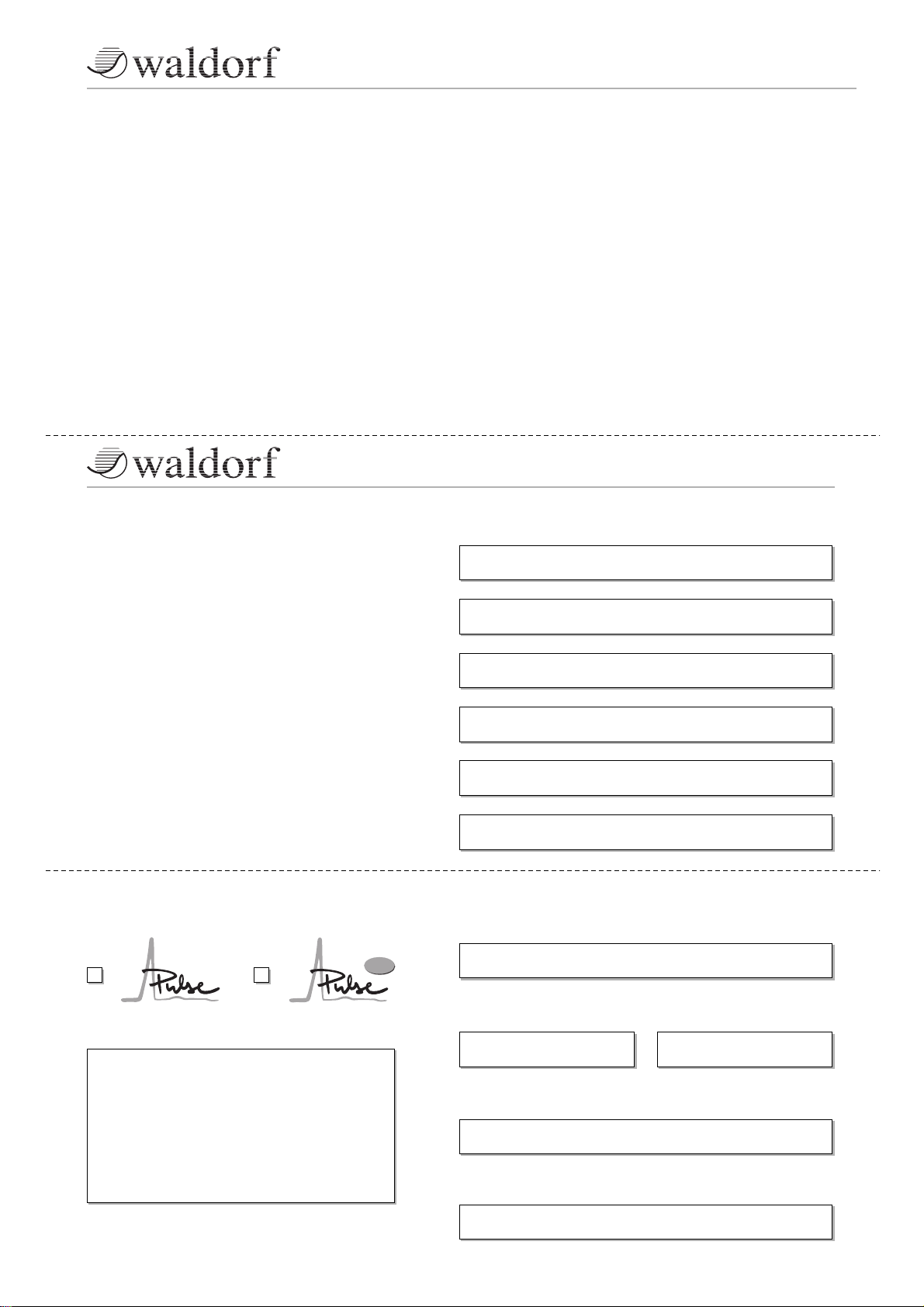
Diagram 2: Selecting programs
Use the Scroll keys ▲ 햻 and ▼ 햽 to select programs. The currently selected program is
indicated by the display 햴 .
☞ This is how you select a sound program.
• Press ▲ 햻 briefly to select the next program.
• Press ▼ 햽 briefly to select the previous program.
To Scroll through a number of programs quickly, press the appropriate Scroll key and
hold it down. After approx. 1 second, the display will Scroll faster. Once the desired
program is indicated in the display, release the Scroll key. More acceleration can be
archived by pressing down the opposite Scroll key while holding down the first Scroll
key. In this case, the program no. is changed in steps of 10.
Example: Program 72
Version number of the operating
software
Example: 1.25
MOD SOURCES
DESTINATIONS
MIDI
CompareStore
User’s Manual Pulse • PulsePlus
15
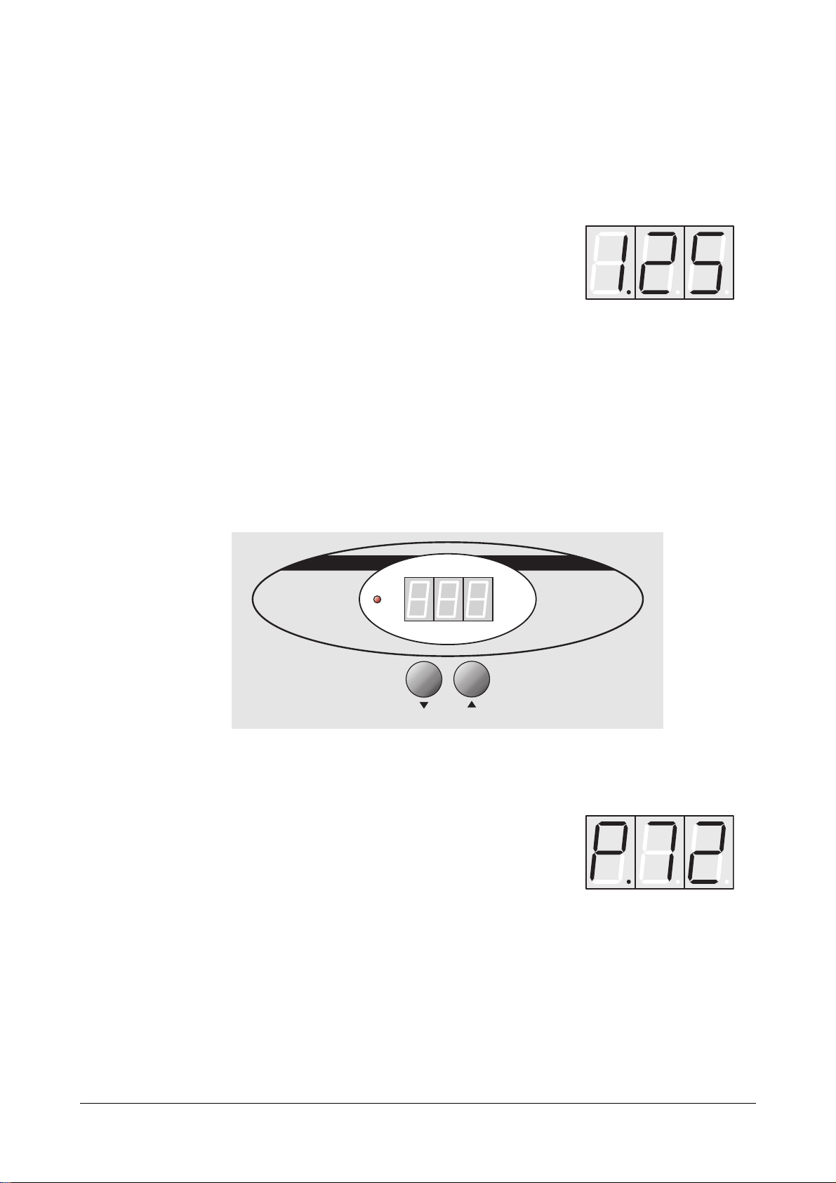
Random Program
If you Scroll beyond program 99, you will see the program P.rn, i.e. a random program.
When you select this program, the Pulse will generate a sound at random.
When the Pulse switches off, its memory stores the last active program and reactivates this
program when the Pulse switches back on. However, any edits you did not save are lost
when the Pulse switches off.
7.3 Editing Sound Parameters
In order to change or edit a sound in the Pulse, you must access the appropriate
parameters. These sound parameters are arranged in a matrix. Accessing parameters
requires two steps: First you must select the desired parameter level. Then you can use the
rotary pots located below the six columns to edit the parameter directly. The parameters
and how they function are described in detail in the next chapter.
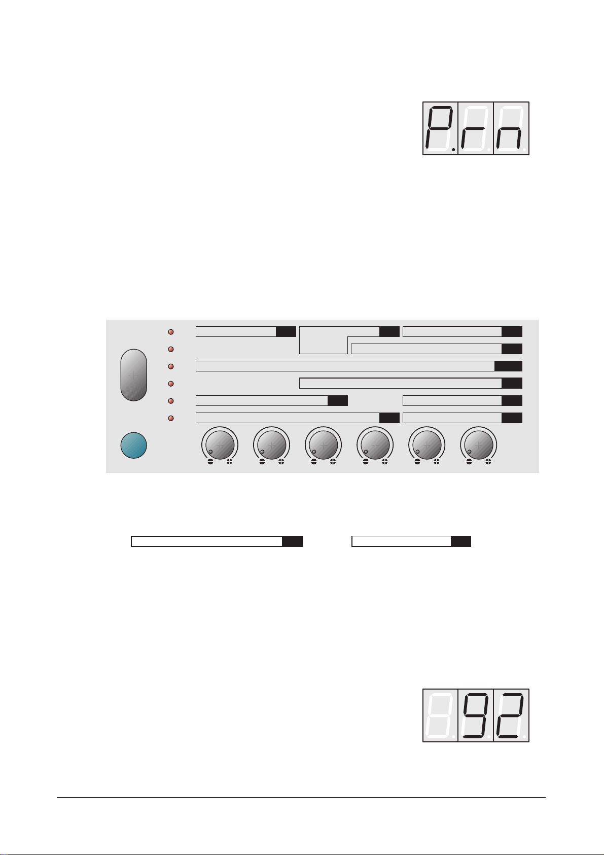
Diagram 3: Parameter matrix
According to the extended functionality of the Pulse Plus, the parameter groups
MIX
and
GLB
differ slightly from the shown diagram:
Please read the chapter about the corresponding parameter group in this manual.
☞ This is how you access a desired parameter:
• Press the Mode key 햶 repeatedly until the LED 햷 next to the desired parameter
level illuminates.
• Alternatively, you can press and hold the Mode key 햶, and use the Scroll keys ▲
햻 and ▼ 햽 to select the desired level.
• Press the control feature 햹 located below the column 햸 containing the desired
parameter.
The display will indicate this
parameter's current value.
Select Value
GLB
Osc 1 Osc 2 / External Osc 3 / Noise
MIX
Random program
Mode
Dump
Semitone / Tune
LFO1 Speed / Shape LFO2 Speed / Delay
Attack Decay Sustain Release Keytrack Trigger
Pitch Mod / Source Portamento / Mode
Active / Range Tempo / Clock Mode
Cutoff / Keytrack Env1 Sens / Velo Sens Cutoff Mod / Source Resonance
Shape / PW
Semitone / Tune
OSC1
Sync / Keytrack
Select Source Amount Destination
Shape / PW
Osc 1 Osc 2 Osc 3 / Noise
Pitchbend Scale
ARP
Semitone / Tune
OSC2
Mastertune / Control X MIDI Channel / ID
Volume / Velo Sens Panning
VCF
Shape
OSC3
MIX
ENV1/2
MOD
GLB
VCA
Shift

16
User’s Manual Pulse • PulsePlus
Several parameter values are not indicated as numerals, but as alphabetic
abbreviations. Please consult the chapter entitled "The Sound Parameters" for further
information.
Several of the Pulse's sound parameters are accessed via the rotary pots' alternate
functions. These parameters are identified in orange lettering on the front panel. You have
two options for editing these parameters:
• Press and hold the Shift key 햺 while adjusting the rotary pots 햹 .
• You also can briefly press the Shift key 햺.
The LED 햷 located next to this parameter level will flash. This indicates that the
rotary pots now adjust the parameters marked in orange.
Press the Shift key 햺 again to return to the previous status.
When you change a parameter value, the current program is automatically in Edit mode.
The letter E. will appear in front of the progam number in the display.
The Pulse is equipped with a feature called an edit buffer. It enables you to activate other
programs without deleting the changes you made to the current program. However, as soon
as you begin editing another program, the modifications you made to the previous program
are lost.
Caution: Make sure you save the modifications you made before you begin
editing the next program. If you fail to save the changes, they will be
irretrievably lost! The next section describes how to save
modifications.
☞ Example: How to change a filter cutoff frequency:
• The desired parameter is entitled Cutoff and is located in the
VCF
group (bottom
line).
• Press the Mode key 햶 repeatedly until the LED 햷 next to the bottom parameter
level illuminates.
• The filter cutoff frequency, aptly entitled Cutoff is located in the first column. Turn
the appropriate rotary pot 햹 , i.e. the first one from the left.
• Observe the value as it changes in the display 햴.
Example: Program 27 in Edit mode

User’s Manual Pulse • PulsePlus
17
7.4 The Store Function
After you have finished editing a program, you must save it if you intend to use it again. The
program memory locations 1 through 40 are available for this purpose.
☞ This is how you store a program:
• Press and hold the Shift key 햺 .
• Briefly press the Scroll key ▼ 햽. This Scroll key's alternate function is Store,
indicated in orange lettering.
• Release the Shift key 햺 .
• A flashing S. appears in front of the selected program number in the display:
The indicated memory location number will always be from 1 to 40, i.e. within the
range of the freely programmable memory locations. If you have edited a factory
preset program, it must be stored in one of these memory locations. The Pulse will
suggest a program number equivalent to the original number plus 40.
Original Program Suggested Program
1...40 1...40
41...80 1...40
81...99 1...19
P.rn 20
• If you want to store the program at a memory location other than the suggested
one, use the Scroll keys ▲ and ▼ to select the desired program number.
• Press and hold the Shift key 햺 and press the Store key 햽 again.
You have now stored the program.
When you activate the Store function, Edit or Compare modes are terminated.
By pressing the Mode key 햶 , you can terminate the process at any time before you
press the Store key 햽 for the final time.
Example: Program 9 is the selected
memory location
18
User’s Manual Pulse • PulsePlus
7.5 The Compare Function
The Compare function allows you to compare the edited sound parameters to their original
values.
☞ This is how you activate the Compare function:
• Press and hold the Shift key 햺 .
• Briefly press the Scroll key ▲ 햻. This Scroll key's alternate function is Compare,
indicated in orange lettering.
• Release the Shift key 햺 .
• A flashing C. appears in front of the selected program number in the display 햴 .
• You will now hear the unedited version when you play your MIDI keyboard.
• Press and hold the Shift key 햺 and press the Compare key 햻 again.
• The edited version of the program is now active.
Please note that parameters cannot be edited when the Compare function is active. If
you select a new program while the Compare function is active, the Compare status
is automatically terminated.
7.6 Deleting Edits
You can void edits at any time and return to the original program.
☞ This is how you delete the edits:
• Press the Shift key 햺 and hold it down.
• Press the Compare key 햻 and hold it down.
• After approx. 2 seconds, the C in the display is replaced by P.
• Release the Shift 햺 and Compare 햻 keys.
All edits have been deleted and the program is back in its original state.
7.7 Viewing Parameter Values
You can also view the value of a parameter without changing it.
☞ This is how you can check out a parameter value:
• Select the appropriate parameter via the Mode key 햶.
• To view a parameter that is accessible via an alternate function, briefly press the
Shift key 햺 so that this parameter level's LED 햷 illuminates.
• Press and hold the Mode key 햶.
• Turn the parameter's rotary pot 햹.
• The parameter value appears in the display 햴.
The value does not change when you turn the rotary pot.
• Release the Mode key 햶.
If the currently active program is in Compare status, the original parameter value will
appear in the display when you turn the pot.
Example: Program 14 in Compare status
User’s Manual Pulse • PulsePlus
19
8. Sound Parameters
8.1 Overview of Functions
The Waldorf Pulse consists of numerous sound-shaping components. The following
overview gives you an idea of how the individual components interact:
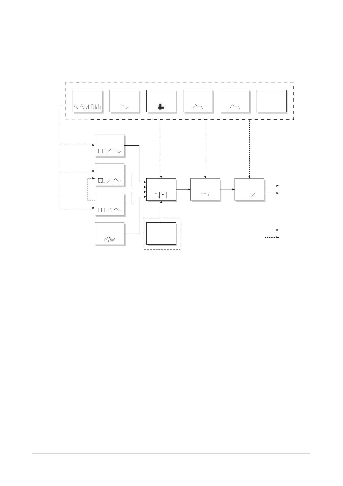
Diagram 4: Block schematic diagram for the Pulse
As you can see, the Pulse consists of two different types of components for sound
generation and sound shaping:
• Oscillators, mixer, filter, VCA.
Sound generation actually occurs within the oscillators. They produce square,
sawtooth and triangular waveshapes. The mixer follows the oscillators in the signal
chain, which is where the oscillators' output signals are mixed. Pink noise can also
be added to the mix. The filter then shapes the sound by amplifying (boosting) or
attenuating (dampening) certain frequencies. The VCA is located at the end of the
signal chain. It is an amplifier that determines the overall volume and position of
the signal within the stereo panorama.
• Modulators: LFOs, Modulation Matrix, Envelopes.
The modulators are designed to manipulate or modulate the sound generating
components to add dynamics to sounds. The low-frequency oscillators (LFOs) are
designed for periodic or recurring waveshapes and envelopes for modulations that
occur once within a given time frame. These generators are assigned to parameters
via the modulation matrix and influence these parameters to alter a sound.
Available modulations include pitch, waveshape, volume, filter settings, etc.
On the Pulse Plus, you can feed in an additional audio signal.
Slave
Master
Sync
L
R
Lowpass Filter
VCF
Volume & Pan
VCA
Output
Mixer
MIX
Oscillator 1
OSC1
Noise
Generator
Envelope 1
ENV1
Envelope 2
ENV2
LF-Oscillator 1
LFO1
LF-Oscillator 2
LFO2
Modulation Matrix
MOD
Global
Parameters
GLB
Audio signal
Control signal
Oscillator 2
OSC2
Oscillator 3
OSC3
Cross Modulation
external
Audiosignal
Pulse Plus only
20
User’s Manual Pulse • PulsePlus
8.2 Oscillators
Oscillators are the heart of every synthesizer. They produce the sound that is later shaped
by the filter and other components. The Waldorf Pulse is equipped with three oscillators,
each of which has different features.
Oscillator 1
Oscillator 1 delivers a periodic oscillation where you can determine waveshape and
frequency. The frequency is defined by the pitch of the notes that are sent via MIDI.
Maximum pitch is approx. 8,5 kHz. The following parameters are available:
Semitone -48...+48 Determines the pitch of the oscillator in semitone
steps.
Tune -32...+31 Fine-tunes the oscillator in increments of 64ths of a
semitone.
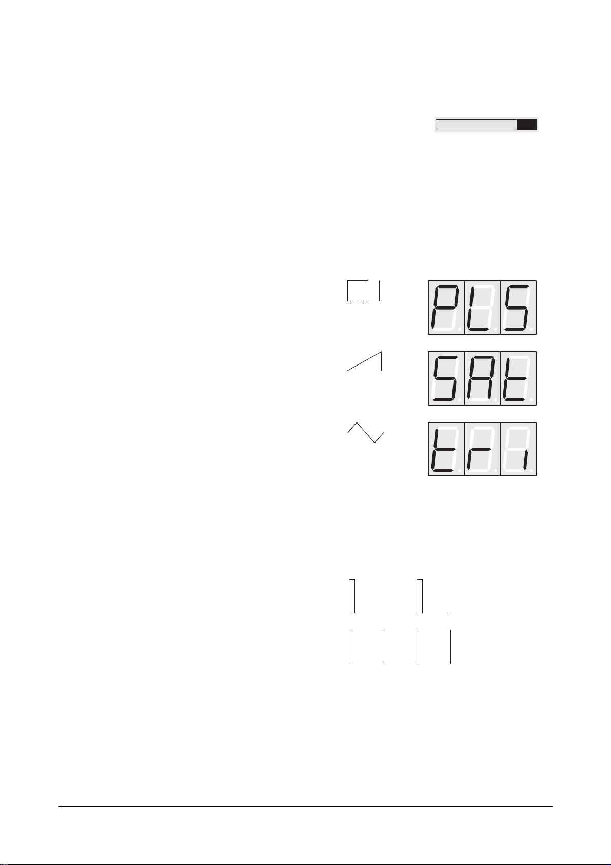
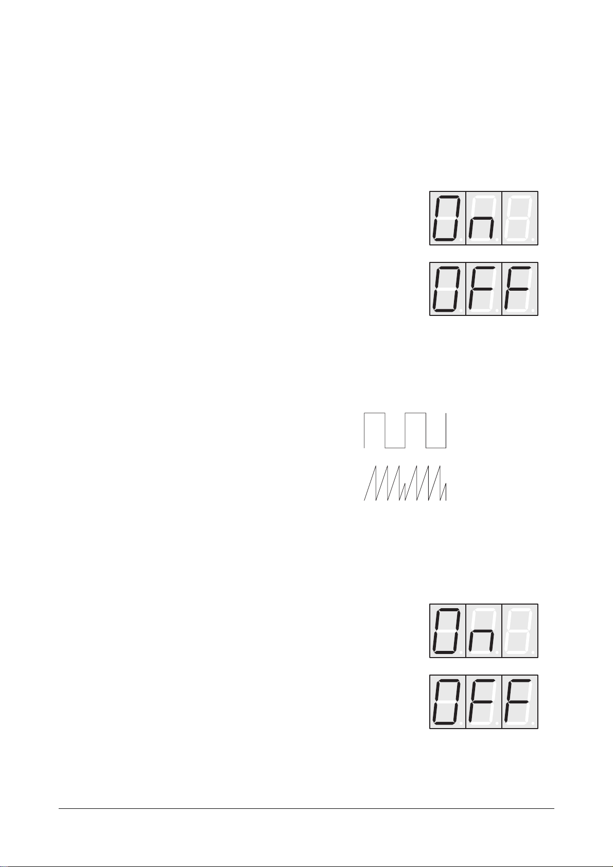
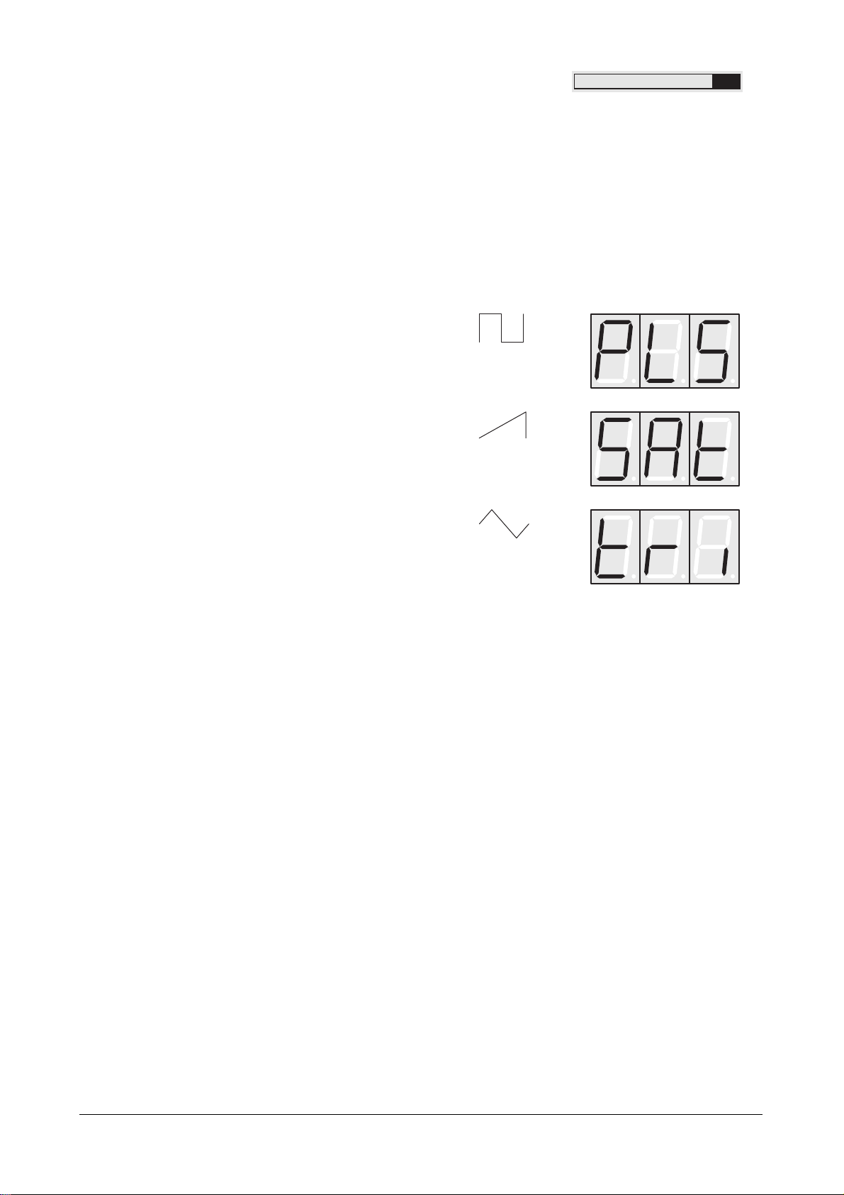
Shape Determines the type of waveshape to be generated.
The following waveshapes are available:
PW 0...127 Determines the pulsewidth of the square wave. If you
select a waveshape other than pulse, than this
parameter has no influence on that waveshape.
PW stands for pulsewidth. If you select a square waveshape, you can determine its
pulsewidth. The value 0 is equivalent to a pulse ratio of 1%, the value 127 is
equivalent to 50%.
Diagram 5: Pulsewidth Modulation
PW=0
PW=127
Triangle
Sawtooth
Pulse: square with variable
pulsewidth
Semitone / Tune
Shape / PW
OSC1
User’s Manual Pulse • PulsePlus
21
Oscillator 2
Similar to Oscillator 1, the second oscillator produces oscillations with variable
waveshapes and frequencies. Available parameter settings are identical to those of
Oscillator 1, with several additional options.
Semitone -48...+48 Determines the pitch of the oscillator in semitone
steps.
Tune -32...+31 Fine-tunes the oscillator in increments of 64ths of a
semitone.
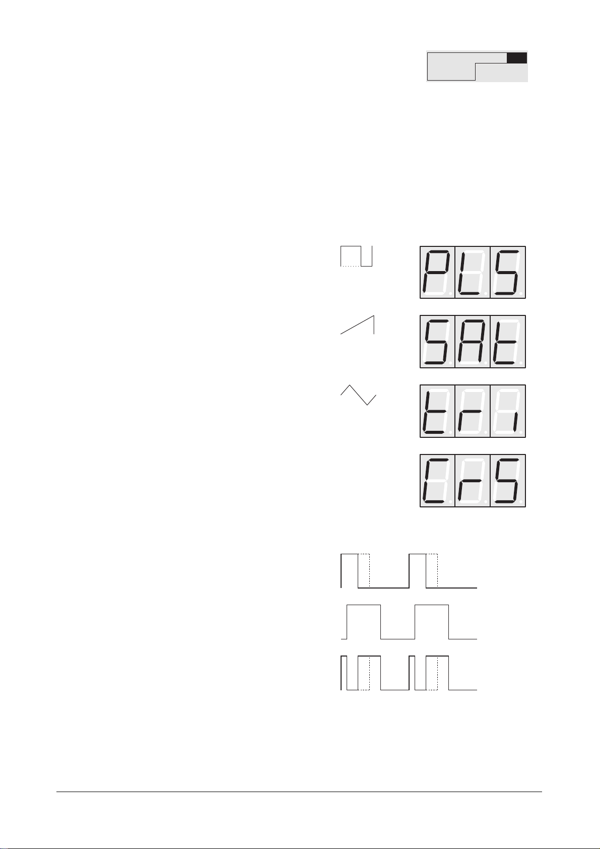
Shape Determines the type of waveshape to be generated.
The following waveshapes are available:
Crossmodulation is a XOR combination of the square waveshapes of
Oscillators 2 and 3:
Diagram 6: Crossmodulation
It produces a waveshape that contains the sum of as well as the
difference between the two original waveshapes.
Oscillator 2
Oscillator 3
Crossmodulation
Crossmodulation
Triangle
Sawtooth
Pulse: square with variable
pulsewidth
Semitone / Tune
Sync / Keytrack
Shape / PW
OSC2
22
User’s Manual Pulse • PulsePlus
Although Oscillator 3's square waveshape is used for crossmodulation, it does not
mean that this square waveshape must be used as the source signal. Because the
crossmodulation is purely internal, you can select another waveshape for Oscillator 3
if you so desire. Please note that you can also modulate Oscillator 2's pulsewidth at
any time. Additionally, you can switch synchronization on and off independently.
PW 0...127 Determines the pulsewidth of the square wave. If you
select a waveshape other than pulse, than this
parameter has no influence on that waveshape.
Sync Switches synchronization with Oscillator 3 on and off.
When the oscillators are in sync, Oscillator 2 is the slave and
Oscillator 3 is the master, i.e. Oscillator 3 controls its counterpart.
At each new periodic cycle of the master oscillator, the waveshape of
the slave oscillator is also started, which leads to interesting effects.
These are especially evident when the two oscillators are operating at
different frequencies.
Diagram 7: Oscillator Synchronisation
Synchronization is possible with all of Oscillator 2's waveshapes. You can also freely
select the waveshape for Oscillator 3.
Keytrack Determines if the pitch of the oscillator is dependent on the MIDI note
number.
The pitch remains at the value you
entered for "Semitone" and "Tune",
regardless of the note you play.
Pitch changes in proportion to the
incoming MIDI notes
Oscillator 3
Oscillator 2
in Sync
Synchronization off
Synchronization on
User’s Manual Pulse • PulsePlus
23
Oscillator 3
Similar to Oscillators 1 and 2, the third oscillator produces oscillations with variable
waveshapes and frequencies. However, it does not feature variable pulsewidth. The
oscillator's highest frequency lies an octave lower than that of Oscillators 1 and 2, at
approx. 4,25kHz.
Semitone -48...+48 Determines the pitch of the oscillator in semitone
steps.
Tune -32...+31 Fine-tunes the oscillator in increments of 64ths of a
semitone.
Shape Determines the type of waveshape to be generated.
The following waveshapes are available:
Noise Generator
In addition to the oscillators, a noise generator that produces pink noise is available. The
noise generator has just one parameter: volume. Volume is determined via the mixer.
Triangle
Sawtooth
Pulse: square
Semitone / Tune
Shape
OSC3

24
User’s Manual Pulse • PulsePlus
8.3 Mixer
The mixer is used to determine volume for the three oscillators and the noise generator.
On the Pulse Plus you can also set the volume of the external audio signal.
Osc1 0...127 Volume of Oscillator 1
Osc2 0...127 Volume of Oscillator 2
Osc3 0...127 Volume of Oscillator 3
Noise 0...127 Volume of the Noise Generator
External 0...127 Volume of the external audio signal
The mixer's output sends the signal to the filter's input. The Pulse is designed to enable you
to overdrive this signal. Saturation occurs at the following values:
• If you program a sound using just one oscillator, then the signal is overdriven
somewhere in the volume value range of 40.
• If you use more than one oscillator, a volume value of approx. 30 is the overdrive
threshold for each oscillator.
The option of overdriving the signal vastly enhances the variety of sounds the Pulse
can produce. The Pulse is an analog device, so we can't give you a precise value
when a signal will be overdriven. As the volume increases, the signal becomes
slightly saturated and flows seamlessly into total disortion.
An overdriven signal has a richer sound, as overtones are added to the clean signal.
This is especially interesting in conjunction with sawtooth and triangular waveshapes,
as square waveshapes are inherently very similar in structure to other overdriven
waveshapes.
Distortion is most audible when you drastically detune several oscillators in relation
to each other, especially over a range of several octaves. This effect is even more
interesting when you tune the pitch of one oscillator a semitone or several semitones
above or below the true octave.
Osc 1 Osc 2 Osc 3 / Noise
MIX
Osc 1 Osc 2 / External Osc 3 / Noise
MIX
 Loading...