

WAGNER Leopard 48-110, Leopard 35-150, Leopard 35-70, Wildcat 10-70, Tiger 72-300 Service Manual
...Page 1

II 2G IIB c T3 X
B_00343
"?
B_00365
Wildcat Puma
10-70 28-40
18-40 15-70
Leopard 21-110
35-70 15-150
35-150 Jaguar
48-110 75-150
Tiger
72-300
IceBreaker Pumps
Feed volume 40 ccm - 300 ccm
Edition 01/2012
Translation of the original
Service manual
Page 2

Page 3

3
40 ccm - 300 ccm.
SERVICE MANUAL
EDITION 01/2012 PART NO. DOC367866
Contents
1 ABOUT THESE INSTRUCTIONS 5
1.1 Languages 5
1.2 Warnings, notes and symbols in these instructions 6
2 GENERAL SAFETY INSTRUCTIONS 7
2.1 Safety instructions for the operator 7
2.1.1 Electrical equipment 7
2.1.2 Personnel qualifi cations 7
2.1.3 A safe work environment 7
2.2 Safety instructions for staff 7
2.2.1 Safe handling of WAGNER spray units 8
2.2.2 Earth the unit 8
2.2.3 Paint hoses 8
2.2.4 Cleaning 9
2.2.5 Handling hazardous liquids, varnishes and paints 9
2.2.6 Touching hot surfaces 9
2.3 Correct use 9
2.4 Use in an explosion hazard area 10
2.4.1 Correct use 10
2.4.2 Explosion protection identifi cation 10
2.4.3 Identifi cation X 10
2.4.4 German regulations and guidelines 11
3 GUARANTEE AND CONFORMITY DECLARATIONS 12
3.1 Important notes on product liability 12
3.2 Guarantee claim 12
3.3 CE-conformity 13
4 PRODUCT DESCRIPTION 14
4.1 Modular structure 14
4.2 Date 15
4.2.1 Materials of the parts transporting paint 15
4.2.2 Recommended V-packings 15
4.2.3 Technical data 16
4.2.3.1 Technical Data for Wildcat, Puma 16
4.2.3.2 Technical data for Leopard, Jaguar and Tiger 17
5 REPAIRS 18
5.1 Tools, test devices and assembly aids 18
5.2 Dismantling / mounting 19
6 FUNCTIONAL TEST 20
6.1 Field-test preparation 20
6.2 Dead point test 20
6.3 Pump running-in 20
6.4 Testing air motor for air leaks 21
6.5 Testing pump for fl uid leaks 21
6.6 Function test 22
6.7 Test data table 23
Page 4

4
40 ccm - 300 ccm.
SERVICE MANUAL
EDITION 01/2012 PART NO. DOC367866
Contents
7 SPARE PARTS 24
7.1 How to order spare parts? 24
7.2 Over views modules 25
7.2.1 Wildcat, Puma, Leopard and Jaguar 25
7.2.2 Tiger 29
7.3 Air motors 30
7.3.1 Air motors Wildcat, Puma, Leopard 30
7.3.2 Air regulator for air motors Wildcat, Puma and Leopard 34
7.3.3 Air motor Jaguar 35
7.3.4 Regulator for Jaguar 40
7.3.5 Air motor Tiger 41
7.3.6 Regulator for air motor Tiger 46
7.4 Material pumps 47
7.4.1 Material pumps 40 ccm 47
7.4.2 Material pumps 70 ccm 50
7.4.3 Material pump 110 ccm 53
7.4.4 Material pumps 150 ccm 56
7.4.5 Material pumps 300 ccm 59
7.5 High-pressure fi lter 62
7.5.1 High-pressure fi lter Wildcat, Puma, Leopard, Jaguar 62
7.5.2 High-pressure fi lter Tiger 64
7.6 Filter-relief combination 66
7.7 Distributor 67
7.8 Trolley 68
7.9 Trolley „Heavy Duty“ 69
7.10 Lifting trolley pneumatic 70
7.11 Lifting trolley 74
7.12 Wall lifting gear pneumatic 76
7.13 Wall lifting gear 80
8 ACCESSORIES 82
8.1 Accessories for Wildcat and Puma pumps 82
8.2 Accessories for Leopard and Jaguar pumps 89
8.3 Accessories for Tiger 95
Page 5

5
40 ccm - 300 ccm.
SERVICE MANUAL
EDITION 01/2012 PART NO. DOC367866
1 ABOUT THESE INSTRUCTIONS
1.1 LANGUAGES
367865 367866
These service instructions contain information on the maintenance and repair of the units.
For further information on technical data and accessories, please see the respective operating instructions.
The manuals respective are available in the following languages:
WILDCAT, PUMA, LEOPARD, JAGUAR
Language Part No. Language Part No.
German 367850 English 367851
French 367852 Dutch 367853
Italian 367854 Spanish 367855
Danish 367857 Swedish 367856
Portuguese 367859 Turkish 367858
Polish 367864 Greek 2309490
TIGER
Language Part No. Language Part No.
German 370850 English 370851
French 370852 Dutch 370853
Italian 370854 Spanish 370855
Danish 370857 Swedish 370856
The service instructions are available under the following order numbers:
Language: Part No. Language: Part No.
German English
Page 6

6
40 ccm - 300 ccm.
SERVICE MANUAL
EDITION 01/2012 PART NO. DOC367866
1.2 WARNINGS, NOTES AND SYMBOLS IN THESE INSTRUCTIONS
Warning instructions in this manual point out particular dangers to users and equipment
and state measures for avoiding the hazard.
These warning instructions fall into the following categories:
Danger - imminent danger. Non-observance will result
in death, serious injury and serious material damage.
Warning - possible danger. Non-observance can result
in death, serious injury and serious material damage.
Caution - a possibly hazardous situation.
Non-observance can result in minor injury.
Note - provide information on particular characteristics and how to proceed.
Caution - a possibly hazardous situation.
Non-observance can cause material damage.
SIHI_0100_GB
DANGER
This line warns of the hazard!
Possible consequences of failing to observe the warning instructions.
The signal word points out the hazard level.
The measures for preventing the hazard and its consequences.
SIHI_0103_GB
WARNING
This line warns of the hazard!
Possible consequences of failing to observe the warning instructions.
The signal word points out the hazard level.
The measures for preventing the hazard and its consequences.
SIHI_0101_GB
C AUTION
This line warns of the hazard!
Possible consequences of failing to observe the warning instructions.
The signal word points out the hazard level.
The measures for preventing the hazard and its consequences.
SIHI_0102_GB
CAUTION
This line warns of the hazard!
Possible consequences of failing to observe the warning instructions . The signal word
points out the hazard level.
The measures for preventing the hazard and its consequences.
Page 7

7
40 ccm - 300 ccm.
SERVICE MANUAL
EDITION 01/2012 PART NO. DOC367866
2 GENERAL SAFETY INSTRUCTIONS
2.1 SAFETY INSTRUCTIONS FOR THE OPERATOR
2.1.1 ELECTRICAL EQUIPMENT
2.1.2 PERSONNEL QUALIFICATIONS
2.1.3 A SAFE WORK ENVIRONMENT
2.2 SAFETY INSTRUCTIONS FOR STAFF
Keep these operating instructions to hand near the unit at all times.
Always follow local regulations concerning occupational safety and accident prevention.
Electrical plant and unit
To be provided in accordance with the local safety requirements with regard to the
operating mode and ambient influences.
May only be maintained by skilled electricians or under their supervision.
Must be operated in accordance with the safety regulations and electrotechnical
regulations.
Must be repaired immediately in the event of problems.
Must be put out of operation if they pose a hazard.
Must be de-energized before work is commenced on active parts. Inform staff about
planned work, observe electrical safety regulations.
%NSURETHATTHEUNITISOPERATEDANDREPAIREDONLYBYTRAINEDPERSONS
Make sure that the floor in the area where you are working is derivable in accordance
with EN 61340-4-1.
Ensure that all persons within the working area wear derivable shoes.
Ensure that during spraying, persons wear derivable gloves so that they are earthed via
the handle of the spray gun.
Customer to provide paint mist extraction units conforming to local regulations.
Ensure that the following components of a safe working environment are available:
– Material/air hoses adapted to the working pressure
– Personal safety equipment (breathing and skin protection)
Ensure that there are no ignition sources such as naked flame, glowing wires or hot
surfaces in the vicinity. Do not smoke.
Always follow the information in these instructions, particularly the general safety
instructions and the warning instructions.
Always follow local regulations concerning occupational safety and accident
prevention.
Page 8

8
40 ccm - 300 ccm.
SERVICE MANUAL
EDITION 01/2012 PART NO. DOC367866
2.2.1 SAFE HANDLING OF WAGNER SPRAY UNITS
2.2.2 EARTH THE UNIT
2.2.3 PAINT HOSES
The spray jet is under pressure and can cause dangerous injuries.
Avoid injection of paint or cleaning agents:
Never point the spray gun at people.
Never reach into the spray jet.
Before all work on the unit, in the event of work interruptions and functional faults:
– Switch off the energy/compressed air supply.
– Secure the spray gun against actuation.
– Relieve the pressure from the spray gun and unit.
– By functional faults: Identify and correct the problem, proceed as described in
chapter „Trouble shooting“.
In the event of skin injuries caused by paint or cleaning agents:
Note down the paint or cleaning agent that you have been using.
Consult a doctor immediately.
Avoid danger of injury through recoil forces:
Ensure that you have a firm footing when operating the spray gun.
Only hold the spray gun briefly in any one position.
Depending on the electrostatic charge and the flow speed of the spray, an electrostatic
charge may occur in the equipment. This could cause a spark or flame on discharging.
Ensure that the unit is earthed for every spraying operation.
Earth the work pieces being painted.
Ensure that all persons inside the working area are earthed, e.g. that they are wearing
derivable shoes.
When spraying, wear derivable gloves to earth yourself via the spray gun handle.
Ensure that the hose material is chemically resistant to the sprayed materials.
Ensure that the material hose is suitable for the pressure generated in the unit.
Ensure that the following information is visible on the high pressure hose:
– Manufacturer
– Permissible operating overpressure
– Date of manufacture.
The electrical resistance of the complete high pressure hose must be less than 1 MOhm.
Page 9

9
40 ccm - 300 ccm.
SERVICE MANUAL
EDITION 01/2012 PART NO. DOC367866
2.2.4 CLEANING
2.2.5 HANDLING HAZARDOUS LIQUIDS, VARNISHES AND PAINTS
2.2.6 TOUCHING HOT SURFACES
2.3 CORRECT USE
De-energize the unit electrically.
Disconnect the pneumatic supply line.
Relieve the pressure from the unit.
Ensure that the flash point of the cleaning agent is at least 5 K above the ambient
temperature.
To clean, use only solvent-free cloths and brushes. Never use hard objects or spray on
cleaning agents with a gun.
An explosive gas/air mixture forms in closed containers.
When cleaning units with solvents, never spray into a closed container.
Earth the container.
When preparing or working with paint and when cleaning the unit, follow the working
instructions of the manufacturer of the paints, solvents and cleaning agents being
used.
Take the specified protective measures, in particular wear safety goggles, protective
clothing and gloves, as well as hand protection cream if necessary.
Use a mask or breathing apparatus if necessary.
For sufficient health and environmental safety: Operate the unit in a spray booth or on
a spraying wall with the ventilation (extraction) switched on.
Wear suitable protective clothing when working with hot materials.
➞ Touch hot surfaces only if you are wearing protective gloves.
➞ When operating the unit with a coating material with a temperature of > 43 °C; 109.4 °F:
- Identify the unit with a warning label that says „Warning - hot surface“.
Order No.
9998910 Information label
9998911 Safety label
7!'.%2ACCEPTSNOLIABILITYFORANYDAMAGEARISINGFROMINCORRECTUSE
5SETHEUNITONLYTOWORKWITHTHEMATERIALSRECOMMENDEDBY7!'.%2
/PERATETHEUNITONLYASANENTIREUNIT
$ONOTDEACTIVATESAFETYEQUIPMENT
5SEONLY7!'.%2ORIGINALSPAREPARTSANDACCESSORIES
Page 10

10
40 ccm - 300 ccm.
SERVICE MANUAL
EDITION 01/2012 PART NO. DOC367866
2.4.1 CORRECT USE
2.4.2 EXPLOSION PROTECTION IDENTIFICATION
2.4.3 IDENTIFICATION X
2.4 USE IN AN EXPLOSION HAZARD AREA
4HEUNITISSUITABLEFORWORKINGLIQUIDMATERIALSINACCORDANCEWITHTHECLASSIlCATIONINTO
EXPLOSIONCLASSES
As defined in the Directive 94/9/EC (ATEX 95), the unit is suitable for use in areas where
there is an explosion hazard.
II 2G IIB c T3 X
CE: Communautés Européennes
Ex: Symbol for explosion protection
II: Unit class II
2: Category 2 (Zone 1)
G: Ex-atmosphere gas
IIB: Explosion group
c: Constructional security
T3: Temperature class: maximum surface temperature < 200 °C; 392 °F.
X: Special Notes (see chapter 2.4.3)
Maximum surface temperature
The maximum surface temperature of the piston pump can be reached if it runs dry.
Ensure that the piston pump is filled with sufficient working or cleaning medium.
Ensure that the separating fluid container is filled with sufficient separating fluid.
Ignition temperature of the coating material
Ensure that the ignition temperature of the coating material is above the maximum
surface temperature.
Ambient temperature
The permissible ambient temperature is +5 °C to +60 °C; +41 °C to 140 °F
Medium supporting atomizing
To atomize the material, use only weakly oxidizing gases, e.g. air.
Mechanical sparks can form if the unit comes into contact with metal
In an explosive atmosphere:
Do not knock or push the unit against steel or rusty iron.
Do not drop the unit.
Use only tools that are made of a permitted material.
Page 11

11
40 ccm - 300 ccm.
SERVICE MANUAL
EDITION 01/2012 PART NO. DOC367866
Cleaning
If there are deposits on the surfaces, the unit may form electrostatic charges. Flames or
sparks can form if there is a discharge.
Remove deposits from the surfaces to maintain conductivity.
Use only a damp cloth to clean the unit.
Surface spraying, electrostatic
Do not spray unit parts with electrostatic (e.g. electrostatic spray gun).
2.4.4 GERMAN REGULATIONS AND GUIDELINES
a) BGR 500 Part 2, Chap. 2.36 Working with liquid ejection devices
b) BGR 500 Part 2, Chap. 2.29 Using coating materials
c) BGR 104 Explosion protection rules
d) TRBS 2153 Avoiding ignition risks
e) BGR 180 Setting up for cleaning with solvents for cleaning workpieces with
solvents
f) ZH 1/406 Guidelines for liquid ejection devices
g) BGI 740 Painting rooms and equipment
h) Betr.Sich.V. Plant Safety Ordinance
Note: All titles can be ordered from Heymanns Publishing House in Cologne,or they are
to be found in the Internet.
Page 12

12
40 ccm - 300 ccm.
SERVICE MANUAL
EDITION 01/2012 PART NO. DOC367866
3 GUARANTEE AND CONFORMITY DECLARATIONS
3.1 IMPORTANT NOTES ON PRODUCT LIABILITY
3.2 GUARANTEE CLAIM
As a result of an EC regulation, effective as from January 1, 1990, the manufacturer shall
only be liable for his product if all parts come from him or are approved by him, and if the
devices are properly fitted , operated and maintained.
If other makes of accessory and spare parts are used, the manufacturer‘s liability could be
fully or partially null and void.
The usage of original WAGNER accessories and spare parts guarantees that all safety
regulations are observed.
Full guarantee is provided for this device:
We will at our discretion repair or replace free of charge all parts which within 24 months
in single-shift, 12 months in 2-shift or 6 months in 3-shift operation from date of receipt by
the Purchaser are found to be wholly or substantially unusable due to causes prior to the
sale, in particular faulty design, defective materials or poor workmanship.
The type of guarantee provided is such that the device or individual components of the
device are either replaced or repaired as we think fit. The resulting costs, in particular
shipping charges, road tolls, labour and material costs will be borne by us except where
these costs are increased due to the subsequent shipment of the unit to a location other
than the address of the purchaser.
We do not provide guarantee for damage that has been caused or contributed to for the
following reasons:
Unsuitable or improper use, faulty installation or commissioning by the purchaser or a
third party, normal wear, negligent handling, defective maintenance, unsuitable coating
products, substitute materials and the action of chemical, electro chemical or electrical
agents, except when the damage is attributable to us.
Abrasive coating products such as red lead, emulsions, glazes, liquid abrasives, zinc dust
paints and similar reduce the service life of valves, packings, spray guns, tips, cylinders,
pistons etc. Signs of wear and tear due to such causes are not covered by this guarantee.
Components that have not been manufactured by WAGNER are subject to the original
guarantee of the manufacturer.
Replacement of a component does not extend the period of guarantee of the device.
The unit should be inspected immediately upon receipt. To avoid losing the guarantee, we
or the supplier company are to be informed in writing about obvious faults within 14 days
upon receipt of the device.
We reserve the right to have the guarantee compliance met by a contracting company.
The services provided by this guarantee depend on evidence being provided in the form
of an invoice or delivery note. If an examination discovers that no guarantee claim exists,
the costs of repairs are charged to the purchaser.
It is clearly stipulated that this guarantee claim does not represent any constraint to statutory
regulations or regulations agreed contractually in our general terms and conditions.
J. Wagner AG
Page 13
13
40 ccm - 300 ccm.
Wildcat Puma Leopard Jaguar Tiger
10-70 28-40 35-70 75-150 72-300
18-40 15-70 35-150 38-300 17-1200
21-110 48-110 9-1200
15-150 18-300
8-300 8-600
3-600 4-1200
II 2G IIB c T3 X
SERVICE MANUAL
EDITION 01/2012 PART NO. DOC367866
3.3 CE-CONFORMITY
CE Certificate of Conformity
The certificate is enclosed with this product. The certificate of conformity can be reordered
from your WAGNER representative, quoting the product and serial number.
Part number :
Herewith we declare that the supplied version of
Pneumatic pumps and spraypacks
Complies with the following guidelines;
2006/42/EG 94/9/EG Atex-directives
Applied standards, in particular:
DIN EN ISO 12100-1: 2004 DIN EN 809: 2011 DIN EN 12621/A1: 2010
DIN EN ISO 12100-1/A1: 2009 DIN EN 14462: 2005 DIN EN 13463-1: 2009
DIN EN ISO 12100-2: 2004 DIN EN ISO 14121-1: 2007 DIN EN 13463-5: 2004
DIN EN ISO 12100-2/A1: 2009 DIN EN 1127-1: 2008
DIN EN ISO 13732-1: 2008 DIN EN 12621: 2006
Applied national technical standards and specifi cations, in particular:
BGR 500 Part 2 Chap. 2.29 and Chap. 2.36 BGR 104 TRBS 2153
Marking:
2302304
Page 14
14
40 ccm - 300 ccm.
B_02326
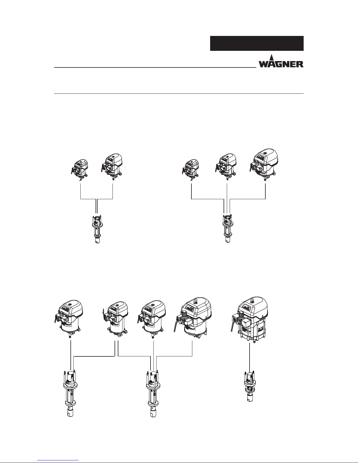
WILDCAT
Ø 80 mm
H 75 mm
Ø 3 inch
S 3 inch
PUMA
Ø 100 mm
H 75 mm
Ø 4 inch
S 3 inch
WILDCAT
Ø 80 mm
H 75 mm
Ø 3 inch
S 3 inch
PUMA
Ø 100 mm
H 75 mm
Ø 4 inch
S 3 inch
LEOPARD
Ø 150 mm
H 75 mm
Ø 6 inch
S 3 inch
WILDCAT 18-40
PUMA 28-40
WILDCAT 10-70
PUMA 15-70
LEOPARD 35-70
PUMA
Ø 100 mm
H 150 mm
Ø 4 inch
S 6 inch
LEOPARD
Ø 150 mm
H 150 mm
Ø 6 inch
S 6 inch
LEOPARD
Ø 150 mm
H 150 mm
Ø 6 inch
S 6 inch
JAGUAR
Ø 220 mm
H 150 mm
Ø 9 inch
S 6 inch
TIGER
Ø 300 mm
H 150 mm
Ø 13 inch
S 6 inch
PUMA 15-150
LEOPARD 35-150
JAGUAR 75-150
TIGER 72-300
LEOPARD 48-110
PUMA 21-110
40 cm
3
300 cm
3
150 cm
3
70 cm
3
110 cm
3
SERVICE MANUAL
EDITION 01/2012 PART NO. DOC367866
4 PRODUCT DESCRIPTION
4.1 MODULAR STRUCTURE
Page 15

15
40 ccm - 300 ccm.
SERVICE MANUAL
EDITION 01/2012 PART NO. DOC367866
4.2 DATE
4.2.1 MATERIALS OF THE PARTS TRANSPORTING PAINT
Housing Stainless steel
Piston Stainless steel and hard chrome
Valve balls Stainless steel
Valves seats Hard chrome (without Type ESS -> Stainless steel)
O-rings Tefl on
V-packings Standard PE/ TG
PE = Polyethylen UHMW
TG = Tefl on (PTFE) with graphite
4.2.2 RECOMMENDED V-PACKINGS
Wagner V-packings are manufactured in four different materials:
Code Material Colour
L Leather dark brown
TG Tefl on with graphite black
PE Polyethylen UHMW transparent
T Tefl on white
Each material has the following properties, which infl uence the packings:
LTGPET
Mechanical stability low good good low
Coeffi cient of friction low very good good very good
Sealing capacity good* good good good
Chemical resistance or
reactivity
low good very good very good
Temperature stability good low - good very good low
* for abrasive materials
Standard combinations
Standard pneumatic pumps PE/TG
Heavy duty (HD) pumps PE/L
Hardener pump in 2C-Systems PE/T
Page 16

16
40 ccm - 300 ccm.
SERVICE MANUAL
EDITION 01/2012 PART NO. DOC367866
4.2.3 TECHNICAL DATA
4.2.3.1 TECHNICAL DATA FOR WILDCAT, PUMA
Description
Units WILDCAT
10-70
WILDCAT
18-40
PUMA
28-40
PUMA
15-70
PUMA
21-110
PUMA
15-150
Transmission ratio 10 :1 18 :1 28 : 1 15 :1 21:1 15 :1
Flow volume per double stroke (DS) cm³; cc 70 40 40 70 110 150
Maxi. operating over pressure MPa
bar
psi
8
80
1160
14.4
144
2089
22.4
224
3249
12
120
1740
16.8
168
2436
12
120
1740
Maxi. possible strokes in operation DH/min
DS/min
60 60 60 60 60 60
Min. Maxi. incoming air pressure MPa
bar
psi
0.25-0.8
2.5-8
36-116
0.25-0.8
2.5-8
36-116
0.25-0.8
2.5-8
36-116
0.25-0.8
2.5-8
36-116
0.25-0.8
2.5-8
36-116
0.25-0.8
2.5-8
36-116
Ø Incoming air (inside threads) Zoll Inch G 1/2“ G 1/2“ G 1/2“ G 1/2“ G 1/2“ G 1/2“
Min. Ø compressed air hose mm; Inch 9; 0.354 9; 0.354 9; 0.354 9; 0.354 9; 0.354 9; 0.354
Air consumption at 0.6 MPa; 6 bar; 87
psi per DS
nl
scf
5.3
0.19
5.3
0.19
8.3
0.29
8.3
0.29
16.5
0.58
16.5
0.58
Sound pressure level at maxi.
permissible air pressure*.
dB(A) 77 77 78 77 78 78
Sound pressure level at 0.6 MPa; 6
bar; 87 psi air pressure*
dB(A) 74 74 74 74 74 74
Sound pressure level at 0.4 MPa; 4
bar; 58.01 psi air pressure*
dB(A) 69 69 69 69 69 69
Ø piston of air motor mm; Inch 80; 3.2 80; 3.2 100; 4 100; 4 100; 4 100; 4
Mat. inlet connection (inside threads) Zoll Inch G 1“ G 3/4“ G 3/4“ G 1“ G 1“ G 1“
Material outlet connection (inside
threads)
Zoll Inch G 3/8“ G 3/8“ G 3/8“ G 3/8“ G 3/8“ G 3/8“
Weight kg; lb 17; 38 15; 33 16; 35 18; 40 28; 62 28; 62
Material pH value pH 3.5 ÷ 9
Maxi. material pressure at pump inlet MPa;bar; psi 2; 20; 290
Material temperature °C; °F +5° ÷ +80°; +41 ÷ +176
Ambient temperature °C; °F +5° ÷ +60° +41 ÷ +140
Allowable sloping position at work <) ° ± 10
* A rated sound pressure level measured at 1 m distance according to DIN EN 14462: 2005.
Reference measurements have been made by SUVA (Swiss accident insurance institute).
WARNING
Outgoing air containing oil!
Risk of poisoning if inhaled
Function problem airmotor
Provide water-free and oil-free compressed air (quality standard
5.5.4 as per ISO 8573.1) 5.5.4 = 40 μm / +7 / 5 mg/m³.
SIHI_0068_GB
Page 17

17
40 ccm - 300 ccm.
SERVICE MANUAL
EDITION 01/2012 PART NO. DOC367866
4.2.3.2 TECHNICAL DATA FOR LEOPARD, JAGUAR AND TIGER
Description Units LEOPARD
35-70
LEOPARD
48-110
LEOPARD
35-150
JAGUAR
75-150
Tiger
72-300
Transmission ratio 35 : 1 48 :1 35 : 1 75:1 72 :1
Flow volume per double stroke (DS) cm³; cc 70 110 150 150 300
Maxi. operating over pressure MPa
bar
psi
25
250
3626
37
370
5366
27
270
3916
53
530
7687
53
530
7687
Maxi. possible strokes in operation DH/min
DS/min
60 60 60 60 40
Min. - Maxi. air inlet pressure MPa
bar
psi
0.25-0.71
2.5-7.1
36-103
0.25-0.8
2.5-8
36-116
0.25-0.77
2.5-7.7
36-112
0.25-0.71
2.5-7.1
36-103
0.25-0.74
2.5-7.4
36-107
Ø air inlet (inside threads) Zoll Inch G 1/2“ G 1/2“ G 1/2“ G 1“ G 1“
Min. Ø compressed air hose mm; Inch 13; 0.512 13; 0.512 13; 0.512 25; 0.984 25; 0.984
Air consumption at 0.6 MPa; 6 bar; 87 psi
per DS
nl; scf 18.6; 0.66 37.3; 1.32 37.3; 1.32 79.9; 2.82 170; 6
Sound pressure level at maxi.
permissible air pressure*
dB(A) 77 78 80 83 82
Sound pressure level at 0.6 MPa; 6 bar;
87 psi air pressure*
dB(A) 74 74 78 81 80
Sound pressure level at 0.4 MPa; 4 bar;
58 psi air pressure*
dB(A) 71 69 74 74 75
Ø piston of air motor mm; Inch 150; 6 150; 6 150; 6 220; 8.7 320; 12.6
Mat. inlet connection (inside threads) Zoll Inch G 1“ G 1“ G 1“ G 1“ G 1 1/2“
Mat. outlet connection (inside threads) Zoll Inch G 3/8“ G 3/8“ G 3/8“ G 3/8“ G 3/4“
Weight kg; lb 26; 57 36; 79 36; 79 53; 117 80; 176
Material pH value pH 3.5 ÷ 9
Maxi. material pressure at pump inlet MPa; bar; psi 2; 20; 290
Material temperature °C; °F +5° ÷ +80°; +41 ÷ +176
Ambient temperature °C; °F +5° ÷ +60°; +41 ÷ +140
Allowable sloping position at work <) ° ± 10
* A rated sound pressure level measured at 1 m distance according to DIN EN 14462: 2005.
Reference measurements have been made by SUVA (Swiss accident insurance institute).
WARNING
Outgoing air containing oil!
Risk of poisoning if inhaled
Function problem airmotor
Provide water-free and oil-free compressed air (quality standard
5.5.4 as per ISO 8573.1) 5.5.4 = 40 μm / +7 / 5 mg/m³.
SIHI_0068_GB
Page 18

18
40 ccm - 300 ccm.
SERVICE MANUAL
EDITION 01/2012 PART NO. DOC367866
5 REPAIRS
5.1 TOOLS, TEST DEVICES AND ASSEMBLY AIDS
Standard tools:
Single-head engineers jaw wrench SW13; size 0.51 inch
Single-head engineers jaw wrench SW17; size 0.67 inch
Single-head engineers jaw wrench SW19; size 0.75 inch
Single-head engineers jaw wrench SW22; size 0.87 inch
Hexagon key SW5; size 0.2 inch
Hexagon key SW6; size 0.24 inch
Hexagon key SW13; size 0.51 inch
Screwdriver size 1
Screwdriver size 5
Screwdriver Torx T25
Circlip pliers
Other tools:
Mandrel for removing inlet valve seat ø 18.3 mm; 0.72 inch
Assembly arbor ø 15.4 mm; 0.60 inch for spool and sleeve assembly
Torque wrench
Assembly aids:
Lubricant Beacon EP 2
Anti-sieze paste
Loctite 243 / 542
Separating fl uid (Mesamol)
Vaseline
Test devices
Container for testing fl uid (approx. 20 l; 0.70 cf)
Earth cable
Suction system
High-pressure hose
Pressure gauge
Gun and nozzle
Page 19

19
40 ccm - 300 ccm.
SERVICE MANUAL
EDITION 01/2012 PART NO. DOC367866
5.2 DISMANTLING / MOUNTING
See safety regulations in chapter 2!
After disassembly:
Treat all parts with a suitable cleaning agent.
Inspect all parts for traces of wear and replace if necessary.
Change all parts contained in the service set.
SIHI_0004_GB
WARNING
Incorrect maintenance/repair!
Risk of injury and damage to the equipment
Repairs and part replacement may only be carried out by specially
trained staff or a WAGNER service center.
Before all work on the unit and in the event of work interruptions:
- Switch off the energy/compressed air supply.
- Relieve the pressure from the spray gun and unit.
- Secure the spray gun against actuation.
Observe the operating and service instructions when carrying
out all work.
WARNING
Overpressure!
Risk of injury from bursting components
Never change the safety valve setting.
SIHI_0026_GB
SIHI_0134_ENG
WARNING
Flying parts!
Risk of injury
➞ Before dismounting a part from the fan motor, this must be
disconnected from the compressed air system:
1. Remove air hose.
2. Set spherical valve to vent position.
Page 20

20
40 ccm - 300 ccm.
SERVICE MANUAL
EDITION 01/2012 PART NO. DOC367866
6 FUNCTIONAL TEST
6.1 FIELD-TEST PREPARATION
Re-assemble pump and other components on trolley or wall-support. Connect suction and
HP hoses, test gauge, spray gun with suitable nozzle.
SIHI_0117_GB
WARNING
Overpressure!
Risk of injury bursting components
➞ Ensure that the pressure range of all the test components used
lies above the maximum operating pressure of the pump.
6.2 DEAD POINT TEST
Fill pump, hose, gun with test fl uid:
Use 0.6 MPa; 6 bar; 87 psi input air, allow pump to cycle slowly (hold gun open with nozzle
under fl uid level).
Stop pump at change-over points, check for pressure drop. There should be no signifi cant
less of pressure after change-over
Pilot valves may blow at change over.
Aids:
Flow controller
6.3 PUMP RUNNING-IN
Allow pump 0.7-0.8 MPa; 7-8 bar; 101.5-116 psi to cycle with gun open (Raise operating
pressure to maximum).
So pump cycles around 15-20 cycles/min (DS) / min
For 10 minutes
Control cycle rate with tip size. After test, check tightness of fi ttings see chapter 7.2.
Test conductivity between piston and pump housing: <100 k
Attention, this test is
-relevant.
Aids:
Test stand with adjustable fl ow
Test medium oil
Torque wrench
Ohmmeter
Page 21

21
40 ccm - 300 ccm.
B_02327
35
SERVICE MANUAL
EDITION 01/2012 PART NO. DOC367866
6.4 TESTING AIR MOTOR FOR AIR LEAKS
Allow pump to cycle slowly, and stop pump by closing gun at various points in up and
down stroke. Check for any air leaks. Close air-supply ball-valve without relieving and check
for pressure-loss.
1. Check for leaks at air piston by listening for leaking at exhausts with gun closed in both
upwards and downwards directions.
2. Check for leaks at air piston by listening for leaking at exhausts with gun closed in both
upwards and downwards directions.
3. Check fl ange seals.
4. Check air connections to pilot valve.
5. Check ball-valve for leaks in all positions.
6. Check switching point of installed over pressure valve (35) and correct if necessary.
(See chapter 6.7, table columns 1 and 2)
7. Tightness of sliding case combination: Stop pump once in upwards and downwards
stroke respectively and close air supply. The air pressure must not fall below 0.6 MPa, 6
bar; 87 psi within 25 seconds, starting at 0.7 MPa; 7 bar; 101.5 psi.
The test data must be documented and should match the values from the test data table
in chapter 6.7.
Aids:
Test stand
Test medium air
Leakage spray
Stopwatch
Checklist C-367000
6.5 TESTING PUMP FOR FLUID LEAKS
Allow pump to cycle slowly:
Close gun and raise operating air to maxi. pressure. Close gun. Check visnally for leaks at all
joints. The pump piston must not „creep“. Repeat test in opposite cycle direction, e.g.
1. Lower / upper packings and outlet (piston) valve in upwards stroke.
2. Lower packing / inlet valve in downwards stroke.
3. Check complete pump section for leaks.
4. Check all fi ttings / connections for leaks
Aids:
Test stand with HD hose (min. NW6), 53 MPa; 530 bar; 7687 psi; 10 m; 32.8 ft.
Pressure gauge
Test medium oil or water
Page 22

22
40 ccm - 300 ccm.
SERVICE MANUAL
EDITION 01/2012 PART NO. DOC367866
The function test should be carried out according to the pressure shown in column 3 of the
table of „test data“ chapter 6.7.
1. For fi nal pressure, see test data table column 4. Pressure difference between upward
stroke and downward stroke must not exceed that in the table column 5.
2. For start-up at mains pressure, see table column 8.
(The pressure before the pump pressure controller is relevant).
3. Suction head >= 8.2 m; 26.9 ft.
4. Pulsation: The pressure drop at the upper and lower switch-over point must not
exceed the value in column 7 for the dynamic spray pressure (column 6) of the test
data table in chapter 6.7.
Attention:
Depending on the nozzle size.
5. Check idler frequency without gun.
Aim: high frequency (>30 DH/Min), no erratic running.
6.6 FUNCTION TEST
Page 23

23
40 ccm - 300 ccm.
SERVICE MANUAL
EDITION 01/2012 PART NO. DOC367866
Column 1 2 3 4 5 6 7 8
Maxi. air pressure
Maxi. material
pressure
Test pressure air
Test pressure ma-
terial
Differential
pressure upward /
downward stroke
Fluid pressure
(Run-in)
Pulsation
Start-up mains
pressure
WILDCAT
10-70
MPa
bar
psi
0.8
8
116.0
7.4±0.5
74±5
1073±72.5
0.7
7
101.5
6.5±0.5
65±5
943±72.5
0.5
5
72.5
4.0±0.5
40±5
580±72.5
0.7
7
72.5
0.25
2.5
36.3
WILDCAT
18-40
MPa
bar
psi
0.8
8
116.0
14.4±1
144±10
2089±145
0.7
7
101.5
12.6±1
126±10
1827±145
1
10
145
10±1
100±10
1450±145
1.5
15
217.5
0.25
2.5
36.3
PUMA
15-70
MPa
bar
psi
0.8
8
116.0
12±1
120±10
1741±145
0.7
7
101.5
10±1
100±10
1450±145
1
10
145
7±1
70±10
1015±145
2
20
290
0.25
2.5
36.3
PUMA
28-40
MPa
bar
psi
0.8
8
116.0
22±1
220±10
3191±145
0.7
7
101.5
19±1
190±10
2756±145
1
10
145
16±1
160±10
2321±145
1
10
145
0.25
2.5
36.3
PUMA
21-110
MPa
bar
psi
0.8
8
116.0
16±1
160±10
2320±145
0.7
7
101.5
14±1
140±10
2030±145
1
10
145
10±1
100±10
1450±145
1
10
145
0.25
2.5
36.3
PUMA
15-150
MPa
bar
psi
0.8
8
116.0
12±1
120±10
1741±145
0.7
7
101.5
10±1
100±10
1450±145
1
10
145
7±1
70±10
1015±145
2
20
290
0.25
2.5
36.3
LEOPARD
35-70
MPa
bar
psi
0.71
7.1
103
24±1
240±10
3481±145
0.7
7
101.5
23.1±1
231±10
3350±145
1
10
145
20±1
200±10
2901±145
2
20
290
0.25
2.5
36.3
LEOPARD
48-110
MPa
bar
psi
0.8
8
116
35±1
350±10
5076±145
0.7
7
101.5
30.6±1
308±10
4467±145
1
10
145
30±1
300±10
4351±145
2
20
290
0.25
2.5
36.3
LEOPARD
35-150
MPa
bar
psi
0.77
7.7
112
24±1
240±10
3481±145
0.7
7
101.5
23.2±1
232±10
3365±145
1
10
145
20±1
200±10
2901±145
2
20
290
0.25
2.5
36.3
JAGUAR
75-150
MPa
bar
psi
0.71
7.1
103
52±1
520±10
7542±145
0.7
7
101.5
50±1
500±10
7252±145
2
20
290
45±1
450±10
6527±145
2.5
25
362.6
0.25
2.5
36.3
TIGER
72-300
MPa
bar
psi
0.74
7.4
107.3
52±1
520±10
7542±145
0.74
7.4
107.3
52±1
520±10
7542±145
2
20
290
42±1
420±10
6092±145
5
50
72.5
0.25
2.5
36.3
Tolerance MPa
bar
psi
±0.01
±0.1
±1.45
- ±0.01
±0.1
±1.45
- Maxi. - Maxi. Maxi.
6.7 TEST DATA TABLE
Page 24

24
40 ccm - 300 ccm.
SERVICE MANUAL
EDITION 01/2012 PART NO. DOC367866
Always supply the following information to ensure delivery of the right spare part:
Part Number, description and quantity
The quantity need not be the same as the number given in the „Quantity“ column.
This number merely indicates how many of the respective parts are used in each sub
assembly.
The following information is also required to ensure smooth processing of your order:
- Address for the invoice
- Address for delivery
- Name of the person to be contacted in the event of any queries
- Type of delivery required (air freight or mail, sea route or overland route, etc.)
Marks in spare parts lists
Note to column „K“ in the following spare parts lists.
U = Wearing parts
Note: No liability is assumed for wearing parts
L = Not part of standard equipment, available, however, as additional extra.
7 SPARE PARTS
7.1 HOW TO ORDER SPARE PARTS?
SIHI_0004_GB
WARNING
Incorrect maintenance/repair!
Risk of injury and damage to the equipment
Repairs and part replacement may only be carried out by specially
trained staff or a WAGNER service center.
Before all work on the unit and in the event of work interruptions:
- Switch off the energy/compressed air supply.
- Relieve the pressure from the spray gun and unit.
- Secure the spray gun against actuation.
Observe the operating and service instructions when carrying
out all work.
Page 25

25
40 ccm - 300 ccm.
B_00336
3
2
7
6
4
5
8
9
10
11
13
12
1
SERVICE MANUAL
EDITION 01/2012 PART NO. DOC367866
7.2 OVER VIEWS MODULES
7.2.1 WILDCAT, PUMA, LEOPARD AND JAGUAR
WILDCAT
10-70
PE/TG
WILDCAT
10-70
PE/T
WILDCAT
18-40
PE/TG
WILDCAT
18-40
PE/T
WILDCAT
18-40
PE/TG
Valve tappet
WILDCAT
18-40
PE/T
Valve tappet
Item Description No. No. No. No. No. No.
1 Piston pump 366112 366113 366110 366111 366105 366106
2 Material pump 368070 368076 367070 367072 367074 2302057
3 Air motor 366080 366080 366080 366080 366080 366080
4 Spring 367530
5 Coupling 367579 367529
6 Double nipple 368958 (M36x2- G 1“) 367958 (M36x2- G 3/4“)
7 Sealing ring 9974110 9974109
8 Sealing ring 9925024
9 Double nipple
(G 3/8“ -NPSM 3/8“)
367556
10 Adapter (NPSM 3/8“ -NPSM1/4“) 367562
11 Adapter (NPSM 3/8“ -M16x1.5) 367563
12 Earthing cable compl. 236219
13 Molykote DX grease 9992616
Tightening torque
Air motor/ Material pump
25 Nm; 18 lbft
Tightening torque pos. 6 160 Nm; 118 lbft
Tightening torque pos. 9 100 Nm; 74 lbft
Tightening torque pos. 2 with 3
Page 26

26
40 ccm - 300 ccm.
SERVICE MANUAL
EDITION 01/2012 PART NO. DOC367866
PUMA
28-40
PE/TG
PUMA
28-40
PE/T
PUMA
28-40
PE/TG
ESS
PUMA
15-70
PE/TG
PUMA
15-70
PE/T
Item Description No. No. No. No. No.
1 Piston pump 367103 367105 367119 367106 367107
2 Material pump 367070 367072 367073 368070 368076
3 Air motor 367080
4 Spring 367530
5 Coupling 367529 367579
6 Double nipple 367958 (M 36x2-G 3/4“) 368958 (M 36x2-G 1“)
7 Sealing ring 9974109 9974110
8 Sealing ring 9925024
9 Double nipple (G 3/8“ -NPSM 3/8“) 367556
10 Adapter (NPSM 3/8“ -NPSM1/4“) 367562
11 Adapter (NPSM 3/8“ -M16x1.5) 367563
12 Earthing cable compl. 236219
13 Molykote DX grease 9992616
Tightening torque Air motor/ Material pump 25 Nm; 18 lbft
Tightening torque pos. 6 160 Nm; 118 lbft 200 Nm; 148 lbft
Tightening torque pos. 9 100 Nm; 74 lbft
PUMA
15-150
PE/TG
PUMA
15-150
PE/T
PUMA
21-110
PE/TG
PUMA
21-110
PE/L
Item Description No. No. No. No.
1 Piston pump 368114 368115 2319960 2319953
2 Material pump 368071 368073 368077 368079
3 Air motor 367083
4 Spring 367530
5 Coupling 367579
6 Double nipple (M36x2 -G 1“) 368958
7 Sealing ring 9974110
8 Sealing ring 9925024
9 Double nipple (G 3/8“ -NPSM 3/8“) 367556
10 Adapter (NPSM 3/8“ -NPSM1/4“) 367562
11 Adapter (NPSM 3/8“ -M16x1.5) 367563
12 Earthing cable compl. 236219
13 Molykote DX grease 9992616
Tightening torque Air motor/ Material pump 50 Nm; 37 lbft
Tightening torque pos. 6 200 Nm; 148 lbft
Tightening torque pos. 9 100 Nm; 74 lbft
Page 27

27
40 ccm - 300 ccm.
SERVICE MANUAL
EDITION 01/2012 PART NO. DOC367866
LEOPARD
35-70
PE/TG
LEOPARD
35-70
PE/T
LEOPARD
35-150
PE/TG
LEOPARD
35-150
PE/T
LEOPARD
35-150
PE/L
Item Description No. No. No. No. No.
1 Piston pump 368103 368105 368106 368107 368109
2 Material pump 368070 368076 368071 368073 368072
3 Air motor 368080 368081
4 Spring 368530
5 Coupling 368529
6 Double nipple (M36x2 -G 1“) 368958
7 Sealing ring 9974110
8 Sealing ring 9925024
9 Double nipple (G 3/8“ -NPSM 3/8“) 367556
10 Adapter (NPSM 3/8“ -NPSM1/4“) 367562
11 Adapter (NPSM 3/8“ -M16x1.5) 367563
12 Earthing cable compl. 236219
13 Molykote DX grease 9992616
Tightening torque
Air motor/ Material pump
25 Nm; 18 lbft 50 Nm; 37 lbft
Tightening torque pos. 6 200 Nm; 148 lbft
Tightening torque pos. 9 100 Nm; 74 lbft
LEOPARD
48-110
PE/TG
LEOPARD
48-110
PE/T
LEOPARD
48-110
PE/L
Item Description No. No. No.
1 Piston pump (NPSM) 368023 368024 368025
2 Material pump 368077 368078 368079
3 Air motor 368081
4 Spring 368530
5 Coupling 368529
6 Double nipple (M36x2 -G 1“) 368958
7 Sealing ring 9974110
8 Sealing ring 9925024
9 Double nipple (G 3/8“ -NPSM 3/8“) 367556
10 Adapter (NPSM 3/8“ -NPSM1/4“) 367562
11 Adapter (NPSM 3/8“ -M16x1.5) 367563
12 Earthing cable compl. 236219
13 Molykote DX grease 9992616
Tightening torque Air motor/ Material pump 50 Nm; 37 lbft
Tightening torque pos. 6 200 Nm; 148 lbft
Tightening torque pos. 9 100 Nm; 74 lbft
Page 28

28
40 ccm - 300 ccm.
SERVICE MANUAL
EDITION 01/2012 PART NO. DOC367866
JAGUAR
75-150
PE/TG
JAGUAR
75-150
PE/T
JAGUAR
75-150
PE/L
Item Description No. No. No.
1 Piston pump (NPSM) 369121 369123 369122
2 Material pump 368071 368073 368072
3 Air motor 369080 369080 369080
4 Spring 368530
5 Coupling 368529
6 Double nipple 368958
7 Sealing ring 9974110
8 Sealing ring 9925024
9 Double nipple (NPSM) 367556
10 Adapter (NPSM 3/8“ -NPSM1/4“) 367562
11 Adapter (NPSM 3/8“ -M16x1.5) 367563
12 Earthing cable compl. 236219
13 Molykote DX grease 9992616
Tightening torque Air motor/ Material pump 50 Nm; 37 lbft
Tightening torque pos. 6 200 Nm; 148 lbft
Tightening torque pos. 9 100 Nm; 74 lbft
Page 29
29
40 ccm - 300 ccm.
2
9
8
7
3
4
5
1
6
B_00350
11
10
SERVICE MANUAL
EDITION 01/2012 PART NO. DOC367866
Tightening torque
Tiger
72-300
PE/L
Tiger
72-300
PE/TG
Tiger
72-300
PE/T
Item Description No. No.
No.
1
Piston pump (NPSM)
370102 370104 370103
2
Material pump
370070 2302211 370071
3
Air motor
370080
4
Spring
370530
5
Coupling
370529
6
Double nipple
369958
7 Sealing ring 9974126
8 Reducing nipple 2 x 60
0
; A=G3/4“- A=NPSM3/8“ 369657
9 Adapter I=NPSM3/8“- A=M16x1.5 367563
10 Earthing cable compl. 236219
11 Molykote DX grease 9992616
Tightening torque Air motor/ Material pump 70 Nm; 52 lbft
Tightening torque pos. 6 300 Nm; 222 lbft
7.2.2 TIGER
Page 30

30
40 ccm - 300 ccm.
14
23
37
8
25
54
48
35
57
8
37
74
75
75
47
31
81
40
30
9
45
44
13
62
18
69
16
49
12
46
17
16
49
11
42
55
56
10
43
52
50
60
59
61
34
41
5
41
71
6
39
32
2
3
53
33
53
36
51
36
4
47
15
72
58
2-3 Nm; appr. 2 lbft
40 Nm; 30 lbft
10-15 Nm;
7-11 lbft
20-25 Nm; 15-19 lbft
28
25 Nm; 19 lbft
29
B_00258
29
30
110
1
110
106
109
106
108
110
110
107
110
108
109
109
100
SERVICE MANUAL
EDITION 01/2012 PART NO. DOC367866
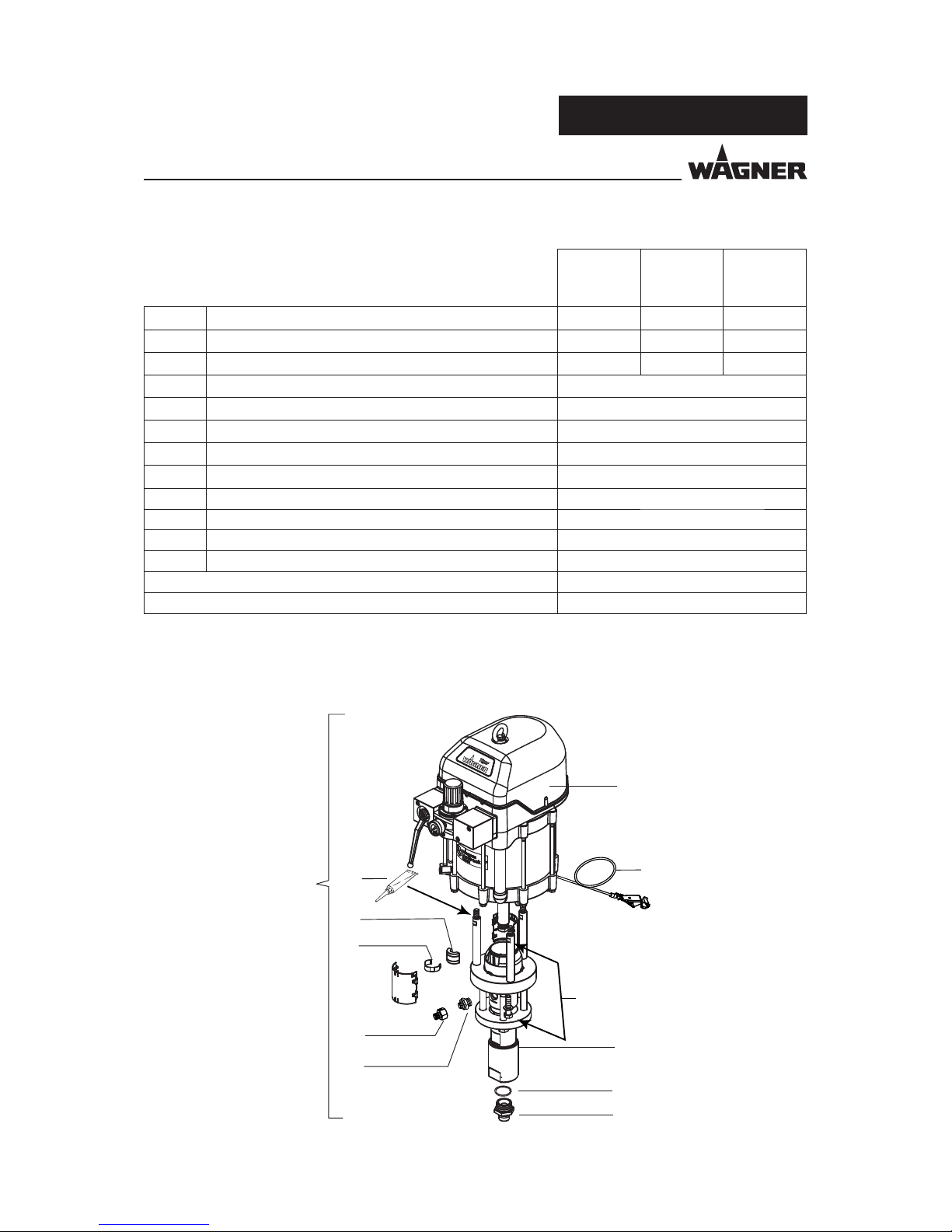
7.3 AIR MOTORS
7.3.1 AIR MOTORS WILDCAT, PUMA, LEOPARD
Do not dismount the piston (Pos. 81)
Pressure regulator (pos. 100)
Detail see paragraph 7.3.2
Page 31

31
40 ccm - 300 ccm.
SERVICE MANUAL
EDITION 01/2012 PART NO. DOC367866
SIHI_0004_GB
WARNING
Incorrect maintenance/repair!
Risk of injury and damage to the equipment
Repairs and part replacement may only be carried out by specially
trained staff or a WAGNER service center.
Before all work on the unit and in the event of work interruptions:
- Switch off the energy/compressed air supply.
- Relieve the pressure from the spray gun and unit.
- Secure the spray gun against actuation.
Observe the operating and service instructions when carrying
out all work.
Spare parts list
Air motor
WILDCAT
Ø80mm/
H75mm
Ø3.1/S3 inch
PUMA
Ø100mm/
H75mm
Ø4/S3 inch
PUMA
Ø100mm/
H150mm
Ø4/S6 inch
LEOPARD
Ø150mm/
H75mm
Ø6/S3 inch
LEOPARD
Ø150mm/
H150mm
Ø6/S6 inch
Pos K Description Qty No. Qty No. Qty No. Qty No. Qty No.
1 Air motor 1 366080 1 367080 11 367083 1 368080 1 368081
2 Flange 1 367316 1 367316 1 367316 1 368316 1 368316
3 Piston rod 1 367302 1 367302 1 367402 1 368302 1 368402
4 Cylinder rod 1 366303 1 367303 1 367403 1 368303 1 368403
5 Compressed air pipe 1 367304 1 367304 1 367404 1 368304 1 368404
6 Control air pipe 1 367305 1 367305 1 367405 1 367305 1 367405
8 Stopper 2 367307 2 367307 2 367307 2 367307 2 367307
9
◆★
Seal, outlet 2 L414.06C 2 L414.06C 2 L414.06C 2 L423.06 2 L423.06
10 Connection piece 1 367309 1 367309 1 367309 1 368309 1 368309
11 Sound absorber 1 367310 1 367310 1 367310 1 368310 1 368310
12 Hood 1 367311 1 367311 1 367311 1 368311 1 368311
13
◆★
Filter, compressed air 1 367313 1 367313 1 367313 1 367313 1 367313
14
◆★
Filter, control air 1 367314 1 367314 1 367314 1 367314 1 367314
15 Casing 1 367312 1 367312 1 367412 1 368312 1 368412
16 Shoulder screw 2 367318 2 367318 2 367318 2 368324 2 368324
17
◆
Sound absorbing mat 1 367319 1 367319 1 367319 1 368319 1 368319
18 Spring pin 2 367320 2 367320 2 367320 2 368320 2 368320
19 Distributor 1 2308791 1 2308791 1 2308791 1 2308793 1 2308793
20
◆
Pressure regulator 1 9998676 1 9998676 1 9998676 1 9999506 1 9999506
20
◆
Pressure regulator XR15 (special accessory)
------19999554 1 9999554
◆ = Wearing part
★ = Included in service set
Page 32

32
40 ccm - 300 ccm.
SERVICE MANUAL
EDITION 01/2012 PART NO. DOC367866
Spare parts list
Air motor
WILDCAT
Ø80mm/
H75mm
Ø3.1/S3 inch
PUMA
Ø100mm/
H75mm
Ø4/S3 inch
PUMA
Ø100mm/
H150mm
Ø4/S6 inch
LEOPARD
Ø150mm/
H75mm
Ø6/S3 inch
LEOPARD
Ø150mm/
H150mm
Ø6/S6 inch
Pos K Description Qty No. Qty No. Qty No. Qty No. Qty No.
21
◆
Angle ball valve -- -- -- -- --
22 Connection piece 2 367322 2 367322 2 367322 2 368322 2 368322
23 Filter location 1 367324 1 367324 1 367324 1 367324 1 367324
24
◆
Stop washer SW9 180 1 9943114 1 9943114 1 9943114 1 9943114 1 9943114
25 Throttle - - - 1 367325 1 367325
26
◆
Handle SW9 1 9943115 1 9943115 1 9943115 1 9943115 1 9943115
27
◆
Hexagon screw 1 9943116 1 9943116 1 9943116 1 9943116 1 9943116
28
◆
O-ring 6 9971123 6 9971123 6 9971123 6 9974142 6 9974142
29
◆
Rod seal 2 9974217 2 9974217 2 9974217 2 9974217 2 9974217
30
◆
Pilot valve 2 369290 2 369290 2 369290 2 369290 2 369290
31
◆
Spool and sleeve assy. 1 9943080 1 9943080 1 9943080 1 9943081 1 9943081
32
◆
Permaglide bush 1 9962018 1 9962018 1 9962018 1 9962019 1 9962019
33
◆
Complete piston 1 9998663 1 9998661 1 9998661 1 9998662 1 9998662
34
◆★
Sealing-wiper ring 1 9974090 1 9974090 1 9974090 1 9974091 1 9974091
35 Safety valve 1 368288 1 368288 1 368288 1 368286 1 368287
36
◆★
O-ring 2 9974115 2 9974084 2 9974084 2 9974087 2 9974087
37
◆★
O-ring 2 9974085 2 9974085 2 9974085 2 9974085 2 9974085
39
◆★
O-ring 2 9974089 2 9974089 2 9974089 2 9974089 2 9974089
40
◆★
O-ring 2 9974095 2 9974095 2 9974095 2 9974096 2 9974096
41
◆★
O-ring 2 9971448 2 9971448 2 9971448 2 9971137 2 9971137
42
◆★
O-ring 1 9974097 1 9974097 1 9974097 1 9974100 1 9974100
43
◆★
O-ring 1 9974098 1 9974098 1 9974098 1 9974101 1 9974101
44 Threaded plug 2 9998674 2 9998674 2 9998674 2 9998674 2 9998674
45 Threaded plug 2 9998274 2 9998274 2 9998274 2 9998274 2 9998274
46 Sticker WAGNER 1 366804 1 367804 1 367804 1 368804 1 368804
47 Threaded plug 2 9998675 2 9998675 2 9998675 2 9998675 2 9998675
48 Control housing 1 367315 1 367315 1 367315 1 368315 1 368315
49 Washer 2 9925033 2 9925033 2 9920106 2 9925026 2 9925026
50 Hexagon screw 3 9900225 3 9900225 3 9907121 3 9900225 3 9907121
51 Hexagon nut 1 9910101 1 9910101 1 9910101 1 9910605 1 9910605
52 Washer 3 9920106 3 9920106 3 9920106 3 9920106 3 9920106
53 Washer 1 9920107 1 9920107 1 9920107 2 9920110 2 9920110
54 Screw SFS 2 9907126 2 9907126 2 9907126 3 9907125 3 9907125
◆ = Wearing part
★ = Included in service set
Page 33

33
40 ccm - 300 ccm.
SERVICE MANUAL
EDITION 01/2012 PART NO. DOC367866
Spare parts list
Air motor
WILDCAT
Ø80mm/
H75mm
Ø3.1/S3 inch
PUMA
Ø100mm/
H75mm
Ø4/S3 inch
PUMA
Ø100mm/
H150mm
Ø4/S6 inch
LEOPARD
Ø150mm/
H75mm
Ø6/S3 inch
LEOPARD
Ø150mm/
H150mm
Ø6/S6 inch
Pos K Description Qty No. Qty No. Qty No. Qty No. Qty No.
55 Cap head screw
M6x16
3 9900325 3 9900325 3 9900325 3 9900313 3 9900313
56 Washer 3 9920103 3 9920103 3 9920103 3 9920102 3 9920102
57
◆★
Sealing ring 1 9970149 1 9970149 1 9970149 1 9970149 1 9970149
58 Base 1 9952668 1 9952668 1 9952668 1 9952668 1 9952668
59 Clamping strap 1 9952667 1 9952667 1 9952667 1 9952667 1 9952667
60 Cap head screw 1 9900701 1 9900701 1 9900701 1 9900701 1 9900701
61 Spring ring 1 9921505 1 9921505 1 9921505 1 9921505 1 9921505
62 Cap head screw 4 9900316 4 9900316 4 9900316 4 9906011 4 9906011
63
◆★
O-ring 1 9974086 1 9974086 1 9974086 1 9974086 1 9974086
64 O-ring 1 3055026 1 3055026 1 3055026 1 3055026 1 3055026
65 O-ring 2 9974105 2 9974105 2 9974105 2 9974102 2 9974102
66 Sealing ring 2 9970149 2 9970149 3 9970149 2 9970148 2 9970148
67 Pressure gauge 1 9998677 1 9998677 1 9998677 1 9998725 1 9998725
69 Pin 1 9998718 1 9998718 1 9998718 1 9998718 1 9998718
70 Plug-in nipple 1 9998810 1 9998810 1 9998810 1 9998813 1 9998813
71 Sticker IceBreaker 1 367806 1 367806 1 367806 1 367806 1 367806
72 Warning sign 1 367807 1 367807 1 367807 1 367807 1 367807
74
◆
Detent body compl.
ISO 1/2
1 368038 1 368038 368038 1 368038 1 368038
75
◆
Absorber ISO 1/2 2 368313 1 368038 368038 1 368038 1 368038
76
◆
O-ring - - - -- --
77
◆
Diaphragm compl. - - - -- --
78
◆
Piston compl. - - - -- --
79
◆
Pressure spring - - - -- --
80
◆
Hand-wheel 1 2315535 1 2315535 1 2315535 - -
81
◆
Spool and sleeve
ISO1 or ISO2
1 9943097 1 9943097 1 9943097 1 9943098 1 9943098
82
◆
Damping washer - - - -- --
100 Pressure regulator
assy. (incl. pos. 62)
1 367060 1 367060 1 367060 1 368060 1 368060
101 Wear parts set for
pos. 20
1 115943 1 115943 1 115943 - - -
106 Loctite 222
50 ml; 50 cc
9992590 9992590 9992590 9992590 9992590
◆ = Wearing part
★ = Included in service set
Page 34

34
40 ccm - 300 ccm.
B_02600
66
66
22
22
45
65
77
82
80
78
76
79
65
64
63
110
108
67
21
24
27
26
20
19
70
110
100
101
SERVICE MANUAL
EDITION 01/2012 PART NO. DOC367866
7.3.2 AIR REGULATOR FOR AIR MOTORS WILDCAT, PUMA AND LEOPARD
Spare parts list
Air motor
WILDCAT
Ø80mm/
H75mm
Ø3.1/S3 inch
PUMA
Ø100mm/
H75mm
Ø4/S3 inch
PUMA
Ø100mm/
H150mm
Ø4/S6 inch
LEOPARD
Ø150mm/
H75mm
Ø6/S3 inch
LEOPARD
Ø150mm/
H150mm
Ø6/S6 inch
Pos K Description Qty No. Qty No. Qty No. Qty No. Qty No.
107 Loctite 243
50 ml; 50 cc
9992511 9992511 9992511 9992511 9992511
108 Loctite 542
50 ml; 50 cc
9992831 9992831 9992831 9992831 9992831
109 Molykote DX grease 9992616 9992616 9992616 9992616 9992616
110 Grease Beacon 9998808 9998808 9998808 9998808 9998808
Service set 1 366995 1 367995 1 367995 1 368995 1 368995
◆ = Wearing part
★ = Included in service set
Page 35

35
40 ccm - 300 ccm.
SERVICE MANUAL
EDITION 01/2012 PART NO. DOC367866
7.3.3 AIR MOTOR JAGUAR
SIHI_0004_GB
WARNING
Incorrect maintenance/repair!
Risk of injury and damage to the equipment
Repairs and part replacement may only be carried out by specially
trained staff or a WAGNER service center.
Before all work on the unit and in the event of work interruptions:
- Switch off the energy/compressed air supply.
- Relieve the pressure from the spray gun and unit.
- Secure the spray gun against actuation.
Observe the operating and service instructions when carrying
out all work.
Spare parts list Air motor Jaguar
JAGUAR
ø220mm
H150mm
ø8.7/S6 inch
Pos K Qty Description No.
1 1 Air motor 369080
2 1 Flange 369316
3 1 Piston rod 368402
4 1 Cylinder pipe 369403
5 2 Compressed air pipe 368404
6 1 Control air pipe 367405
8 1 Sealing plug 369307
9
◆★
2 Seal, outlet 369312
10 1 Connection piece 369309
11 1 Sound absorber 369310
12 1 Hood 369905
13
◆★
1 Filter, compressed air 369313
14
◆★
1 Filter, control air 367314
15 1 Cylinder cover 369412
16 1 Shoulder screw 369318
17
◆
1 Sound absorbing mat 369906
18 2 Spring pin 369320
19 1 Distributor 369321
20
◆
1 Pressure control valve A25R-1 9999452
21
◆
1 Angle ball valve, assy. 369061
22 2 Connection piece 369322
◆ = Wearing part
★ = Included in service set
Page 36

36
40 ccm - 300 ccm.
14
23
37
8
25
54
89
35
57
92
37
74
93
94
31
40
9
13
62
105
109
109
110
110
110
18
83
82
49
95
96
97
81
12
46
17
16
54
80
11
36
55
56
10
103
43
52
50
60
59
61
34
41
5
41
71
72
6
39
32
2
3
53
88
51
75
36
4
47
15
58
8-10 Nm / 6-7 lbft
140 Nm / 103 lbft
40 Nm / 30 lbft
70 Nm / 52 lbft
28
87
77
48
76
79
106
110
108
78
87
85
90
91
40 Nm /
30 lbft
20 Nm
15 lbft
29
B_00277
30
29
30
98
109
106
108
107
110
110
1
33
84
114
1:2
33, 112
84. 113
33, 112
84. 113
SERVICE MANUAL
EDITION 01/2012 PART NO. DOC367866
Do not dismount the
piston (pos. 94)
ATTENTION
Wrong assembly combination form O-Ring
and piston cylinder will damage cylinder!
See assembly instruction on page 6
Pressure regulator (pos. 105)
Detail see chapter 7.3.4
Page 37

37
40 ccm - 300 ccm.
SERVICE MANUAL
EDITION 01/2012 PART NO. DOC367866
Spare parts list Air motor Jaguar
JAGUAR
ø220mm
H150mm
ø8.7/S6 inch
Pos K Qty Description No.
23 1 Filter location 367324
25 1 Throttle 367325
28
◆
6 O-ring 9974 143
29
◆
2 Rod seal 9974217
30
◆
2 Pilot valve 369290
31
◆
1 Spool and sleeve assembly ISO3 369907
32
◆
1 Permaglide bushing 9962019
33
◆
1
Piston (valid for pump serial number „J8-056“ and higher.)
369385
34
◆★
1 Sealing-wiper ring 9974125
35 1 Safety valve 368286
36
◆★
2 O-ring 9974133
37
◆★
2 O-ring 9971056
39
◆★
2 O-ring 9974089
40
◆★
2 O-ring 9974132
41
◆★
4 O-ring 9971137
43
◆★
1 O-ring 9974165
46 1 Sticker WAGNER 369804
47 2 Threaded plug 9998675
48 1 Control housing 369315
49 1 Washer 9925034
50 4 Hexagon head screw 9907137
51 1 Hexagon nut 9910605
52 4 Washer 9920106
53 2 Washer 369303
54 7 Screw SFS 9907125
55 3 Cap head screw 9900314
56 3 Washer 9925029
57
◆★
1 Sealing ring 9970149
58 1 Base 9952668
59 1 Clamping strap 9952667
60 1 Cap head screw 9900701
61 1 Spring ring 9921505
62 4 Cap head screw 9907078
63
◆★
1 O-ring 3051679
64
◆★
1 O-ring 9971092
◆ = Wearing part
★ = Included in service set
Page 38

38
40 ccm - 300 ccm.
SERVICE MANUAL
EDITION 01/2012 PART NO. DOC367866
Spare parts list Air motor Jaguar
JAGUAR
ø220mm
H150mm
ø8.7/S6 inch
Pos K Qty Description No.
65
◆★
2 O-ring 9971009
66
◆★
2 Sealing ring 9974135
67
◆
1 Pressure gauge 9998725
68
◆
1 O-ring 115437
71 1 Sticker Ice Breaker 367806
72 1 Warning sign 367807
73 1 Cone plug 9990543
74
◆
1 Detent body 369027
75 1 Rod seal Profi le E5 9974124
76 2 Angled connection 9992757
77 1 T -fi tting 9992758
78 4 Washer 9920102
79 4 Cap head screw 9900313
80 2 Washer 9925031
81 1 Ring nut 369325
82 1 Shoulder ring 369324
83 1 Hexagon head screw 9900150
84
◆★
1
O-ring (valid for pump serial number „J8-056“ and higher) 9974262
85 1 Air pipe 369306
86 2 Cylindrical shaft 9930834
87
◆
3 O-ring 9971004
88 2 Damping washer 369304
89 1 Control fl ange 369317
90 1 Air hose rear 369026
91 1 Air hose front 369025
92 1 Stop space 9 369326
93
◆
2 Absorber ISO3 369329
94
◆
1 Spool and sleeve ISO3 9943131
95
◆
1 Velcro fastener adhesive part 9999151
96
◆
1 Velcro fastener coating part 9999152
97 1 Adhesive 9992816
98
◆
1 O-ring Viton B 9971372
99
◆
1 Stop washer SW14; size 0.55 inch 180 9943117
100 1 Handle 9943118
101 1 Hexagon screw with washer 9943119
◆ = Wearing part
★ = Included in service set
Page 39

39
40 ccm - 300 ccm.
B_02792
4.325 mm
Ø 5.33 mm
Ø 210.0 mm
5.025 mm
Ø 5.33 mm
Ø 215.67 mm
113
112
84
33
SERVICE MANUAL
EDITION 01/2012 PART NO. DOC367866
Spare parts list Air motor Jaguar
JAGUAR
ø220mm
H150mm
ø8.7/S6 inch
Pos K Qty Description No.
102
◆
1 Diaphragm unit 115435
103
◆
1 Sound absorbing mat 9/12“ 369330
104
◆
1 Hand-wheel 115787
105 1 Pressure regulator unit 9 assy. (incl. pos. 62) 369060
106 1 Loctite 222 50 ml; 50 cc 9992590
107 1 Loctite 243 50 ml; 50 cc 9992511
108 1 Loctite 542 50 ml; 50 cc 9992831
109 1 Anti-sieze paste 9992616
110 1 Grease Beacon 9998808
111 1 Wear parts set A25R-1 (for pos. 20) 115436
112 1
Piston (valid for pump serial number older than „J8-056“)
369305
113
◆★
1
O-ring (valid for pump serial number older than „J8-056“)
9974134
114 1
Piston with o-ring SOFT (wear part)
369971
1 Service set 369987
◆ = Wearing part
★ = Included in service set
Assembly instructions for o-rings item 84 or 113
From pump serial number “J8-056” piston O-ring has changed.
1 o-ring for the old design and 1 o-ring for the new design are included in service set.
In case of service be sure, that the correct o-ring is mounted on the existing piston.
Design older
than pump serial
number “J8-056”
Design newer
than pump serial
number “J8-056”
Control dimension
Control dimension
Piston 9
Page 40

40
40 ccm - 300 ccm.
104
102
86
66
66
22
22
65
65
64
63
108
111
110
110
99
100
101
67
68
21
20
19
B_01982
73
105
SERVICE MANUAL
EDITION 01/2012 PART NO. DOC367866
7.3.4 REGULATOR FOR JAGUAR
Page 41

41
40 ccm - 300 ccm.
SERVICE MANUAL
EDITION 01/2012 PART NO. DOC367866
7.3.5 AIR MOTOR TIGER
Spare parts list Air motor
LUMO Tiger
with regulator
LUMO Tiger
without regulator
Pos K Description Qty No. Qty No.
1 Air motor complete 1 370080 1 370081
2 Shoulder ring 1 369324 1 369324
3 Ring nut 1 369325 1 369325
4
◆
Pressure regulator unit 12 (incl. pos. 40) 1 370060 - -
5 Control air pipe 150 2 367405 2 367405
6 Piston washer 12 1 370303 1 370303
7 Damping washer 12 2 370304 2 370304
8
◆
Piston 12 (valid for pump serial number
„E7-077“ and higher.)
1 370385 1 370385
9 Piston rod 12/150 1 370402 1 370402
10 Hexagon nut 1 9913051 1 9913051
11
◆★
O-ring (valid for pump serial number
„E7-077“ and higher.)
1 9974261 1 9974261
13 Base 1 9952668 1 9952668
14 Clamping strap 1 9952667 1 9952667
15 Spring ring 1 9921505 1 9921505
16 Slotted cheese head screw with slit 1 9900701 1 9900701
17 Gauging pin 1 370307 1 370307
18 Valve cover 2 370309 2 370309
19 Spiral spring 2 370310 2 370310
20 Sealing screw 2 370311 2 370311
21
◆
Valve body 2 370312 2 370312
22 Lock washer 2 9922724 2 9922724
◆ = Wearing part; ★ = Included in service set
WARNING
Incorrect maintenance/repair!
Risk of injury and damage to the equipment
Repairs and part replacement may only be carried out by specially
trained staff or a WAGNER service center.
Before all work on the unit and in the event of work interruptions:
- Switch off the energy/compressed air supply.
- Relieve the pressure from the spray gun and unit.
- Secure the spray gun against actuation.
Observe the operating and service instructions when carrying
out all work.
Page 42

42
40 ccm - 300 ccm.
11, 118
59
10
6
11
8
7
9
35
74
32
31
33
16
15
14
13
20
19
18
22
17
21
23
29
43
41
30
24
25
28
27
26
107
39
3 / 2
44
36
38
46
42
85
37
45
112
116
86
71
73
50
78
60
67
77
52
63
115
116
116
116
114
116
70
72
58
87
57
61
54
56
62
55
66
76
42
66
65
74
53
69
83
74
81
51
40
68
75 a)
48
49
47
4
79
108
115
116
116
1
109
111
111
64
8-10 Nm / 6-7 lbft
200 Nm / 148 lbft
40 Nm / 30 lbft
70 Nm / 51 lbft
20 Nm /
15 lbft
60 Nm / 44 lbft
80
5
B_00357
112
116
116
116
116
113
11, 118
8, 119
8, 119
SERVICE MANUAL
EDITION 01/2012 PART NO. DOC367866
Pressure regulator (pos. 4)
Detail see chapter 7.3.6
Do not dismount the
piston (Pos. 87)
ATTENTION
Wrong assembly combination form
O-ring and piston cylinder will
damage cylinder!
See assembly instruction on page 6
Page 43

43
40 ccm - 300 ccm.
SERVICE MANUAL
EDITION 01/2012 PART NO. DOC367866
Spare parts list Air motor
LUMO Tiger
with regulator
LUMO Tiger
without regulator
Pos K Description Qty No. Qty No.
23
◆
O-ring 2 9974102 2 9974102
24 Flange 12 1 370316 1 370316
25
◆
Permaglide bushing 1 9962026 1 9962026
26
◆
O-ring 1 9971446 1 9971446
27
◆★
Wiper ring D35 1 9974158 1 9974158
28
◆★
Rod seal D35 1 9974159 1 9974159
29 Threaded plug 1 9998675 1 9998675
30 Threaded plug 2 9998274 2 9998274
31 Air pipe 12 1 370306 1 370306
32 Cylinder rod 12/150 1 370403 1 370403
33
◆★
O-ring 1 9971129 1 9971129
35
◆★
O-ring 4 9974089 4 9974089
36 Hood 9 1 369311 1 369311
37
◆
Sound absorbing mat 9 1 369319 1 369319
38 Sticker Wagner 12 Tiger 1 370804 1 370804
39 Hexagon head screw 1 9900150 1 9900150
40 Cap head screw 4 9907078 4 -
41 Hexagon head screw 8 9907208 8 9907208
42 Screw 5 9907125 5 9907125
43 Washer 8 9920107 8 9920107
44 Washer 1 9925034 1 9925034
45 Silencer 9 1 369310 1 369310
46 Shoulder screw 9 1 369318 1 369318
47
◆★
Filter, control air 1 367314 1 367314
48 Filter location 1 367324 1 367324
49 Throttle 1 367325 1 367325
50 Connection piece 9 1 369309 1 369309
51
◆★
Filter, compressed air 9 1 369313 1 369313
52
◆★
Seal, outlet DE 50 2 369312 2 369312
53 Lock washer 12 1 370313 1 370313
54 Sealing plug 12 1 370314 1 370314
55 Control housing 12 1 370315 1 370315
56 Securing ring 2 370330 2 370330
57
◆
Spool and sleeve assembly ISO4 1 9943121 1 9943121
58
◆
O-ring 6 9974160 6 9974160
59 Safety valve 0.78 MPa; 7.8 bar; 113 psi 1 2302480 1 2302480
◆ = Wearing part; ★ = Included in service set
Page 44

44
40 ccm - 300 ccm.
SERVICE MANUAL
EDITION 01/2012 PART NO. DOC367866
Spare parts list Air motor
LUMO Tiger
with regulator
LUMO Tiger
without regulator
Pos K Description Qty No. Qty No.
60
◆★
Sealing ring 1 9970149 1 9970149
61
◆★
O-ring 2 9974092 2 9974092
62 Synthetic union elbow 8-1/4“ 2 9998253 2 9998253
63 Synthetic union elbow 8-1/8“ 2 9992757 2 9992757
64 Air hose front 1 370233 1 370233
65 Air hose rear 1 370234 1 370234
66 Air hose down 2 370235 2 370235
67 Gauging pin 1 370308 1 370308
68 Control fl ange 12 1 370317 1 370317
69 Compressed air pipe 12 1 370404 1 370404
70 Cap head screw 4 9900313 4 9900313
71 Cap head screw 3 9900314 3 9900314
72 Washer 4 9920102 4 9920102
73 Washer 3 9925029 3 9925029
74
◆
O-ring 5 9971004 5 9971004
75
◆★
O-ring 1 9971129 1 9971129
76
◆
O-ring 1 9971372 1 9971372
77
◆★
O-ring 2 9974132 2 9974132
78 Synthetic union elbow 8-1/8“ 1 9992757 1 9992757
79 Fitting L 1 9998613 1 9998613
80 Sticker IceBreaker 1 367806 1 367806
81 Pin for control fl ange 2 370318 2 370318
82 Treated connection straight 1 9992744 1 9992744
83 Treated connection straight 1 9992743 1 9992743
84 Screw SFS Plastite 45 2 9907125 2 9907125
85 Washer 2 9925031 2 9925031
86
◆
O-ring 1 9974165 1 9974165
90 Angle ball valve housing 12 1 370323 1 370323
91 Stop washer SW14 180 1 9943117 - -
92 Handle SW14 2x offset 1 9943118 - -
93 Hexagon head screw with washer 1 9943119 - -
95 Connection piece 1“/30 2 370322 - -
96 Cylindrical shaft 2 9930126 - -
97
◆★
O-ring 2 9971056 - -
98
◆★
O-ring 1 3055026 - -
99
◆★
O-ring 1 9971169 - -
◆ = Wearing part; ★ = Included in service set
Page 45

45
40 ccm - 300 ccm.
B_02791
6 mm
Ø 6.99 mm
Ø 285.1 mm
7.5 mm
Ø 6.99 mm
Ø 297.8 mm
118
119
11
8
SERVICE MANUAL
EDITION 01/2012 PART NO. DOC367866
Spare parts list Air motor
LUMO Tiger
with regulator
LUMO Tiger
without regulator
Pos K Description Qty No. Qty No.
100
◆★
Sealing ring 1“ 2 9974135 - -
101
◆
Pressure control valve A25R-1 1 9999452 - -
102
◆
Diaphragm unit 1 115435 - -
103
◆
O-ring 1 115437 - -
104 Hand-wheel ET 1 115787 - -
105
◆
Pressure gauge 1 9998725 - -
106 Angle ball valve, assy. 1 370061 - -
107 Danger sign 1 367807 1 367807
108
◆
Velcro fastener adhesive part 1 9999151 1 9999151
109
◆
Velcro fastener coating part 1 9999152 1 9999152
110
◆
Distributor 12 1 370321 - -
111 Adhesive „Miranit“ 1 9992816 1 9992816
112
Loctite 222 50 ml; 50 cc
1
9992590
1
9992590
113
Loctite 243 50 ml; 50 cc
1
9992511
1
9992511
114
Loctite 542 50 ml; 50 cc
1
9992831
1
9992831
115
Anti-sieze paste
1
9992616
1
9992616
116
Grease Beacon
1
9998808
1
9998808
117
Wear parts set A25R-1 (for pos. 20)
1
115436
--
118
◆★
O-ring (valid for pump serial number older
than „E7-077“)
1 9974161
119
Piston 12 (valid for pump serial number
older than „E7-077“)
1
370305
--
Service set air motor 12 1 370987 1 370987
◆ = Wearing part; ★ = Included in service set
Assembly instructions for o-rings item 11 or 118
From pump serial number “E7-077” piston O-ring has changed.
1 o-ring for the old design and 1 o-ring for the new design are included in service set.
In case of service be sure, that the correct o-ring is mounted on the existing piston.
Design older
than pump serial
number “E7-077”
Design newer
than pump serial
number “E7-077”
Control dimension
Control dimension
Piston 12
Page 46

46
40 ccm - 300 ccm.
104
102
96
100
100
114
117
103
116
116
116
95
95
97
97
98
99
4
105
106
101
110
B_00359
91
92
93
SERVICE MANUAL
EDITION 01/2012 PART NO. DOC367866
7.3.6 REGULATOR FOR AIR MOTOR TIGER
SIHI_0004_GB
WARNING
Incorrect maintenance/repair!
Risk of injury and damage to the equipment
Repairs and part replacement may only be carried out by specially
trained staff or a WAGNER service center.
Before all work on the unit and in the event of work interruptions:
- Switch off the energy/compressed air supply.
- Relieve the pressure from the spray gun and unit.
- Secure the spray gun against actuation.
Observe the operating and service instructions when carrying
out all work.
Page 47

47
40 ccm - 300 ccm.
SERVICE MANUAL
EDITION 01/2012 PART NO. DOC367866
7.4 MATERIAL PUMPS
7.4.1 MATERIAL PUMPS 40 CCM
SIHI_0004_GB
WARNING
Incorrect maintenance/repair!
Risk of injury and damage to the equipment
Repairs and part replacement may only be carried out by specially
trained staff or a WAGNER service center.
Before all work on the unit and in the event of work interruptions:
- Switch off the energy/compressed air supply.
- Relieve the pressure from the spray gun and unit.
- Secure the spray gun against actuation.
Observe the operating and service instructions when carrying
out all work.
Spare parts list Material pumps
40 cm
³
PE/TG
ESS
40 cm
³
PE/TG
40 cm
³
PE/L
40 cm
³
PE/T
Pos K Qty Description No. No. No. No.
1 1 Material pump complete 367073 367070 - 367072
2 1 Pipe 367502
3 1 Cylinder 367503
4 1 Inlet housing 367504
5
◆
1 Piston 367505
6 1 Valve screw 367506
7
◆★
1 Ball guide inlet 367507
8 1 Connection fl ange 367501
9
◆
1 Valve seat, inlet 367569 367509
10
◆
1 Valve seat, outlet 367570 367510
11 1 Snap ring fl ange 367511
12 2 Snap ring half 367512
13 1 Securing ring 367513
16 1 Support ring 367516
17 1 Thrust collar 367517
18 1 Support ring 367518
19 1 Thrust collar 367519
100
◆
Packing PE/TG compl. (small) 115805
101
◆
Packing PE/T compl. (small) 123219
◆ = Wearing part
★ = Included in service set
● = Special accessories
Page 48

48
40 ccm - 300 ccm.
32
31
44
16
21
20
21
20
21
40
17
2
41
19
23
22
23
103
104
105
100
101
102
22
23
18
5
43
28
10
6
25
12
11
3
13
46
25
7
42
27
9
4
50
51
45
8
70 Nm
+10 Nm
51
1
52
60
52 lbft
+ 7 lbft
B_01275
53
39
40 Nm/ 30 lbft
60
60
25 Nm; 18 lbft
60
60
60
61
62
61
60
SERVICE MANUAL
EDITION 01/2012 PART NO. DOC367866
Item 4 tighten to block manually.
Use a standard spanner only if it‘s
necessary.
In this case use a spanner to
counter on item 3.
Page 49

49
40 ccm - 300 ccm.
SERVICE MANUAL
EDITION 01/2012 PART NO. DOC367866
Spare parts list Material pumps
40 cm
³
PE/TG
ESS
40 cm
³
PE/TG
40 cm
³
PE/L
40 cm
³
PE/T
Pos K Qty Description No. No. No. No.
102
◆
Packing PE/L compl. (small) 115826
20
◆★
2 Sealing collar TG (small) 123398
20
◆
2 Sealing collar T (small) 123426
20
◆
2 Sealing collar L (small) 123402
21
◆★
3 Sealing collar PE (small) 123427
103
◆
Packing PE/TG compl. (large) 367991
104
◆
Packing PE/T compl. (large) 367992
105
◆
Packing PE/L compl. (large) 367993
22
◆★
2 Sealing collar TG (large) 367522
22
◆
2 Sealing collar T (large) 367900
22
◆
2 Sealing collar L (large) 367922
23
◆★
3 Sealing collar PE (large) 367523
25
◆★
2 O-ring 367525
27
◆★
1 O-ring 367527
28
◆★
1 O-ring 367528
31
◆
1 Separating fl uid cup 367531
32
◆
2 Coupling cover 367532
39
◆★
6 O-ring 9974089
40
◆★
1 Wave spring (small) 9998669
41
◆★
1 Wave spring (large) 9998670
42
◆★
1 Ball (large) 9941513
43
◆★
1 Ball (small) 9941518
44
◆★
1 O-ring 9974094
45
◆★
1 O-ring 9974093
46
◆★
1 O-ring 9974106
50 3 Hexagon screw 9907124
51 6 Washer 9920106
52 3 Hexagon screw 9900225
53 3 Connecting pipe 367306
60 Grease Mobilux EP 2 9998808
61 Anti-sieze paste 9992609
62 Molykote DX grease 9992616
1 Service set PE/TG 367990
1 Service set PE/T 367994
◆ = Wearing part
★ = Included in service set
● = Special accessories
Page 50

50
40 ccm - 300 ccm.
SERVICE MANUAL
EDITION 01/2012 PART NO. DOC367866
7.4.2 MATERIAL PUMPS 70 CCM
SIHI_0004_GB
WARNING
Incorrect maintenance/repair!
Risk of injury and damage to the equipment
Repairs and part replacement may only be carried out by specially
trained staff or a WAGNER service center.
Before all work on the unit and in the event of work interruptions:
- Switch off the energy/compressed air supply.
- Relieve the pressure from the spray gun and unit.
- Secure the spray gun against actuation.
Observe the operating and service instructions when carrying
out all work.
Spare parts list Material pumps
70 cm
³
PE/TG
70 cm
³
PE/L
70 cm
³
PE/T
Pos K Qty Description No. No. No.
1 1 Material pump complete 368070 - 368076
2 1 Pipe 368502
3 1 Cylinder 368503
4 1 Inlet housing 368504
5
◆
1 Piston 368505
6 1 Valve screw 368506
7
◆★
1 Ball guide Inlet 368507
8 1 Connection fl ange 368501
9
◆
1 Valve seat inlet 368509
10
◆
1 Valve seat outlet 368510
11 1 Snap ring fl ange 368511
12 2 Snap ring half 368512
13 1 Securing ring 368513
16 1 Support ring 368516
17 1 Thrust collar 367519
18 1 Support ring 368518
19 1 Thrust collar 368519
100
◆
Packing PE/TG compl. (small) 367991
101
◆
Packing PE/T compl. (small) 367992
102
◆
Packing PE/L compl. (small) 367993
20
◆★
2 Sealing collar TG (small) 367522 .
20
◆
2 Sealing collar T (small) 367900
20
◆
2 Sealing collar L (small) 367922
21
◆★
3 Sealing collar PE (small) 367523
103
◆
Packing PE/TG compl. (large) 368991
◆ = Wearing part
★ = Included in service set
● = Special accessories
Page 51

51
40 ccm - 300 ccm.
50
70 Nm
+10 Nm
60
52 lbft
+ 7 lbft
40 Nm/ 30 lbft
60
60
25 Nm
18 lbft
60
60
60
60
61
62
61
60
32
31
44
16
21
20
21
20
21
40
17
2
41
19
23
22
23
103
104
105
100
101
102
22
23
18
5
43
28
10
6
25
12
11
3
13
46
25
7
42
27
9
4
51
45
8
a)
51
52
B_01269
53
39
57
1
SERVICE MANUAL
EDITION 01/2012 PART NO. DOC367866
Item 4 tighten to block manually.
Use a standard spanner only if it‘s
necessary.
In this case use a spanner to
counter on item 3.
Page 52

52
40 ccm - 300 ccm.
SERVICE MANUAL
EDITION 01/2012 PART NO. DOC367866
Spare parts list Material pumps
70 cm
³
PE/TG
70 cm
³
PE/L
70 cm
³
PE/T
Pos K Qty Description No. No. No.
104
◆
Packing PE/T compl. (large) 368992
105
◆
Packing PE/L compl. (large) 368993
22
◆★
2 Sealing collar TG (large) 368522
22
◆
2 Sealing collar T (large) 368900
22
◆
2 Sealing collar L (large) 368922
23
◆★
3 Sealing collar PE (large) 368523
25
◆★
2 O-ring 368525
27
◆★
1 O-ring 368527
28
◆★
1 O-ring 368528
31
◆
1 Separating fl uid cup 367531
32
◆
2 Coupling cover 367532
39
◆★
6 O-ring 9974089
40
◆★
1 Wave spring (small) 9998670
41
◆★
1 Wave spring (large) 9998671
42
◆★
1 Ball (large) 9943082
43
◆★
1 Ball (small) 9941512
44
◆★
1 O-ring 9974092
45
◆★
1 O-ring 9974093
46
◆★
1 O-ring 9974107
50 3 Hexagon head screw 9907124
51 6 Washer 9920106
52 3 Hexagon head screw 9900225
53 3 Connecting pipe 367306
57
●
3 Ball guide for high viscosity materials 369926
60 Grease Mobilux EP 2 9998808
61 Anti-sieze paste 9992609
62 Molykote DX grease 9992616
1 Service set PE/TG 368990
1 Service set PE/T 368994
◆ = Wearing part
★ = Included in service set
● = Special accessories
Page 53

53
40 ccm - 300 ccm.
SERVICE MANUAL
EDITION 01/2012 PART NO. DOC367866
7.4.3 MATERIAL PUMP 110 CCM
SIHI_0004_GB
WARNING
Incorrect maintenance/repair!
Risk of injury and damage to the equipment
Repairs and part replacement may only be carried out by specially
trained staff or a WAGNER service center.
Before all work on the unit and in the event of work interruptions:
- Switch off the energy/compressed air supply.
- Relieve the pressure from the spray gun and unit.
- Secure the spray gun against actuation.
Observe the operating and service instructions when carrying
out all work.
Spare parts list Material pump
110 cm
³
PE/TG
110 cm
³
PE/L
110 cm
³
PE/T
Pos K Qty Description No. No. No.
1 1 Material pump 368077 368079 368078
2 1 Tube 368434
3 1 Cylinder 368435
4 1 Inlet housing 368554
5
◆
1 Piston 368433
6 1 Valve screw 367506
7
◆★
1 Ball guide inlet 368507
8 1 Connection fl ange 368551
9
◆
1 Valve seat, inlet 368509
10
◆
1 Valve seat, outlet 367510
11 1 Snap ring fl ange 368561
12 2 Snap ring half 368512
13 1 Securing ring 368513
16 1 Support ring 368428
17 1 Thrust collar 368425
18 1 Support ring 368430
19 1 Thrust collar 368432
100
◆
Packing PE/TG compl. (small) 368253
101
◆
Packing PE/T compl. (small) - 368297
102
◆
Packing PE/L compl. (small) 368295
◆ = Wearing parts
★ = Included in service set
● = Special accessories
Page 54

54
40 ccm - 300 ccm.
70 Nm
+10 Nm
52 lbft
+ 7 lbft
60
60
60
50 Nm
27 lbft
50 Nm
27 lbft
60
60
60
60
61
61
62
62
61
60
32
31
44
16
21
20
21
20
21
40
17
2
41
19
23
22
23
103
104
105
100
101
102
22
23
18
5
43
28
10
6
25
12
11
3
13
46
25
7
42
27
9
4
50
51
57
45
8
54
55
B_01277
56
160 Nm
118 lbft
1
SERVICE MANUAL
EDITION 01/2012 PART NO. DOC367866
Item 4 tighten to block manually
Use a standard spanner only if it‘s
necessary.
In this case use a spanner to
counter on item 3.
Page 55

55
40 ccm - 300 ccm.
SERVICE MANUAL
EDITION 01/2012 PART NO. DOC367866
Spare parts list Material pump
110 cm
³
PE/TG
110 cm
³
PE/L
110 cm
³
PE/T
Pos K Qty Description No. No. No.
20
◆★
2 Sealing collar TG (small) 368426
20
◆★
2 Sealing collar T (small) 368436
20
◆★
2 Sealing collar L (small) 368437
21
◆★
3 Sealing collar PE (small) 368427
103
◆
Packing PE/TG compl. (large) 368299
104
◆
Packing PE/T compl. (large) 368296
105
◆
Packing PE/L compl. (large) 368294
22
◆★
2 Sealing collar TG (large) 368429
22
◆★
2 Sealing collar T (large) 368438
22
◆★
2 Sealing collar L (large) 368439
23
◆★
3 Sealing collar PE (large) 368431
25
◆★
2 O-ring 368525
27
◆★
1 O-ring 368527
28
◆★
1 O-ring 367528
31
◆
1 Separating fl uid cup 368531
32
◆
2 Coupling cover 368532
40
◆★
1 Wave spring (small) 9998670
41
◆★
1 Wave spring (large) 9998671
42
◆★
1 Ball (large) 9943082
43
◆★
1 Ball (small) 9941518
44
◆★
1 O-ring 9974092
45
◆★
1 O-ring 9974116
46
◆★
1 O-ring 9974107
50 3 Hexagon screw 9907142
51 3 Washer 9925011
54 3 Washer 9920107
55 3 Hexagon screw 9900157
56 3 Threaded bolt 368533
57
●
3 Ball guide for high viscosity materials 369926
60 Grease Mobilux EP 2
9998808
61 Anti-sieze paste
9992609
62 Molykote DX paste
9992616
1 Service Set pump PP110 PE+TG 368997
1 Service Set pump PP110 PE+T 2304930
1 Service Set pump PP110 PE+L 2319924
◆ = Wearing parts
★ = Included in service set
● = Special accessories
Page 56

56
40 ccm - 300 ccm.
SERVICE MANUAL
EDITION 01/2012 PART NO. DOC367866
7.4.4 MATERIAL PUMPS 150 CCM
SIHI_0004_GB
WARNING
Incorrect maintenance/repair!
Risk of injury and damage to the equipment
Repairs and part replacement may only be carried out by specially
trained staff or a WAGNER service center.
Before all work on the unit and in the event of work interruptions:
- Switch off the energy/compressed air supply.
- Relieve the pressure from the spray gun and unit.
- Secure the spray gun against actuation.
Observe the operating and service instructions when carrying
out all work.
Spare parts list Material pumps
150 cm
³
PE/TG
150 cm
³
PE/L
150 cm
³
PE/T
Pos K Qty Description No. No. No.
1 Material pumps complete 368071 368072 368073
2 1 Pipe 368552
3 1 Cylinder 368553
4 1 Inlet housing 368554
5
◆
1 Piston 368555
6 1 Valve screw 368506
7
◆★
1 Ball guide Inlet 368507
8 1 Connection fl ange 368551
9
◆
1 Valve seat inlet 368509
10
◆
1 Valve seat outlet 368510
11 1 Snap ring fl ange 368561
12 2 Snap ring half 368512
13 1 Securing ring 368513
16 1 Support ring 368516
17 1 Thrust collar 367519
18 1 Support ring 368518
19 1 Thrust collar 368519
100
◆
Packing PE/TG compl. (small) 367991
101
◆
Packing PE/T compl. (small) - 367992
102
◆
Packing PE/L compl. (small) 367993
20
◆★
2 Sealing collar TG (small) 367522
20
◆
2 Sealing collar T (small) 367900
◆ = Wearing part
★ = Included in service set
● = Special accessories
Page 57

57
40 ccm - 300 ccm.
70 Nm
+10 Nm
52 lbft
+ 7 lbft
60
60
60
50 Nm
27 lbft
50 Nm
27 lbft
60
60
60
60
61
61
62
62
61
60
32
31
44
16
21
20
21
20
21
40
17
2
41
19
23
22
23
103
104
105
100
101
102
22
23
18
5
43
28
10
6
25
12
11
3
13
46
25
7
42
27
9
4
50
51
57
45
8
54
55
B_01277
56
160 Nm
118 lbft
1
SERVICE MANUAL
EDITION 01/2012 PART NO. DOC367866
Item 4 tighten to block manually.
Use a standard spanner only if it‘s
necessary.
In this case use a spanner to
counter on item 3.
Page 58

58
40 ccm - 300 ccm.
SERVICE MANUAL
EDITION 01/2012 PART NO. DOC367866
Spare parts list Material pumps
150 cm
³
PE/TG
150 cm
³
PE/L
150 cm
³
PE/T
Pos K Qty Description No. No. No.
20
◆
2 Sealing collar L (small) 367922
21
◆★
3 Sealing collar PE (small) 367523
103
◆
Packing PE/TG compl. (large) 368991
104
◆
Packing PE/T compl. (large) 368992
105
◆
Packing PE/L compl. (large) 368993
22
◆★
2 Sealing collar TG (large) 368522
22
◆
2 Sealing collar T (large) 368900
22
◆
2 Sealing collar L (large) 368922
23
◆★
3 Sealing collar PE (large) 368523
25
◆★
2 O-ring 368525
27
◆★
1 O-ring 368527
28
◆★
1 O-ring 368528
31
◆
1 Separating fl uid cup 368531
32
◆
2 Coupling cover 368532
40
◆★
1 Wave spring (small) 9998670
41
◆★
1 Wave spring (large) 9998671
42
◆★
1 Ball (large) 9943082
43
◆★
1 Ball (small) 9941512
44
◆★
1 O-ring 9974092
45
◆★
1 O-ring 9974116
46
◆★
1 O-ring 9974107
50 3 Hexagon screw 9907142
51 3 Washer 9925011
54 3 Washer 9920107
55 3 Hexagon screw 9900157
56 3 Threaded bolt 368533
57
●
3 Ball guide for high viscosity materials 369926
60 Grease Mobilux EP 2 9998808
61 Anti-sieze paste 9992609
62 Molykote DX grease 9992616
1 Service set PE/TG 368990
1 Service set PE/T 368994
◆ = Wearing part
★ = Included in service set
● = Special accessories
Page 59

59
40 ccm - 300 ccm.
SERVICE MANUAL
EDITION 01/2012 PART NO. DOC367866
SIHI_0004_GB
WARNING
Incorrect maintenance/repair!
Risk of injury and damage to the equipment
Repairs and part replacement may only be carried out by specially
trained staff or a WAGNER service center.
Before all work on the unit and in the event of work interruptions:
- Switch off the energy/compressed air supply.
- Relieve the pressure from the spray gun and unit.
- Secure the spray gun against actuation.
Observe the operating and service instructions when carrying
out all work.
Spare parts list HV material pumps
300 cm³
PE/TG
300 cm³
PE/L
300 cm³
PE/T
Pos K Qty Description No. No. No.
1 1 Material pumps complete 300 cm
³
2302211 370070 370071
2 2 Coupling cover Strokes 150 368532
3 1 Support ring 35.8/52-300 369516
4
◆★
3 Sealing collar PE 35.8/ 52 368523
5
◆★
2 Sealing collar L 35.8/ 52 368922
5
◆★
2 Sealing collar TG 35.8/ 52 368522
5
◆
2 Sealing collar T 35.8/ 52 368900
6 1 Thrust collar 35.8/52 368519
7
◆★
1 Wave spring 35.8/52 9998671
8 2 Snap ring half 300 369512
9 1 Securing ring 300 369513
10
◆★
2 O-ring 369525
11
◆
1 Cylinder 300 370503
12 1 Snap ring fl ange 300 370511
13
◆★
1 O-ring 9974118
14 1 Support ring 34/50-300 369518
15
◆★
3 Sealing collar PE 34/50 369523
16
◆★
2 Sealing collar L 34/50 369922
16
◆★
2 Sealing collar TG 34/50 369522
16
◆★
2 Sealing collar T 34/50 369900
17 1 Thrust collar 34/50 369519
18
◆★
1 Wave spring 35.8/52 9998671
◆ = Spare part
★
= Included in service set
7.4.5 MATERIAL PUMPS 300 ccm
Page 60

60
40 ccm - 300 ccm.
60
60
60
62
61
61
60
70 Nm;
52 lbft
70 Nm; 52 lbft
300 Nm; 221 lbft
250
+10
Nm;
184
+7
lbft
60
60
62
60
2
39
35
38
25
36
37
26
3
4
5
4
5
4
6
7
21
24
9
8
12
28
27
29
103
104
105
100
101
102
20
19
23
18
17
15
16
15
16
15
14
22
10
10
13
11
34
31
32
30
33
min. 80 Nm;
min. 59 lbft
B_00339
1
SERVICE MANUAL
EDITION 01/2012 PART NO. DOC367866
Page 61

61
40 ccm - 300 ccm.
SERVICE MANUAL
EDITION 01/2012 PART NO. DOC367866
Spare parts list HV material pumps
300 cm³
PE/TG
300 cm³
PE/L
300 cm³
PE/T
Pos K Qty Description No. No. No.
19
◆
1 Valve seat Outlet 300 369510
20
◆★
1 O-ring 369528
21
◆
1 Piston 300 370505
22 1 Valve screw 300 370506
23 1 Shoulder ring 300 370514
24
◆★
1 Ball 9941505
25 1 Connection fl ange 370501
26 1 Pipe 300 370502
27 4 Hexagon screw 9907210
28 4 Washer 9920110
29
◆★
1 O-ring 9974117
30
◆★
1 Ball guide Inlet 300 369507
31
◆
1 Valve seat Inlet 300 369509
32
◆★
1 O-ring 369527
33 1 Inlet housing 300 370504
34
◆★
1 Ball 9943086
35 3 Threaded bolt M16x169 370533
36 3 Hexagon head screw 9907209
37 3 Washer 9925011
38
◆★
1 O-ring 9974116
39 1 Separating fl uid cup Strokes 150 368531
60
Grease Mobilux EP 2
9998808
61
Anti-sieze paste
9992609
62
Molykote DX grease
9992616
100
◆
1 Packing PE/L compl. 368993
101
◆
1 Packing PE/T compl. 368992
102
◆
1 Packing PE/TG compl. 368991
103
◆
1 Packing PE/L compl. 369993
104
◆
1 Packing PE/T compl. 369992
105
◆
1 Packing PE/TG compl. 369991
- Service set Pump 300 cm³ PE+L 370989
- Service set Pump 300 cm³ PE+TG 369990
- Service set Pump 300 cm
³
PE+T 369964
◆ = Spare part
★ = Included in service set
Page 62

62
40 ccm - 300 ccm.
30
6
100 Nm; 74 lbft
30
30
90 Nm; 66 lbft
23
100 Nm: 74 lbft
80 Nm; 59 lbft
12
11
1
10
2
3
5
7
B_02810
20
21
23
33
33
4
31
90 Nm; 66 lbft
SERVICE MANUAL
EDITION 01/2012 PART NO. DOC367866
7.5 HIGH-PRESSURE FILTER
Identifi cation of
the fi lter
7.5.1 HIGH-PRESSURE FILTER WILDCAT, PUMA, LEOPARD, JAGUAR
Pos. 3 tightened
by hand on block
Ball valve version in: Steel Stainless steel
Item K Qty Description Part No. Part No.
1 High-pressure fi lter HPF-3 3/8” 367175 367178
2 1 Filter housing 367911
3 1 Union nut 367912
4 1 Reducing double nipple with 2 x 60° 367556
5
◆
1 O-ring 367914
6 1 Screwed connector 367916
7 1 Distribution housing 367910
10 1 Filter support 9894245
◆ = Wearing parts
● = Not part of standard equipment for spray gun. Available, however, as additional extra.
Page 63

63
40 ccm - 300 ccm.
SERVICE MANUAL
EDITION 01/2012 PART NO. DOC367866
Ball valve version in: Steel Stainless steel
Item K Qty Description Part No. Part No.
11
◆
1 Filter cartridges *
* Filter cartridge 200 295721
* Filter cartridge 100 3514068
* Filter cartridge 50 3514069
* Filter cartridge 20 291564
12
◆
1 Cone spring 3514058
20
◆
1 Ball valve 9998679 9999159
21 1 Screwed connecting piece 9998680
23 2 Screw plug 9907127
30
◆
3 Sealing ring 9925024
31 1 Adapter I NPSM 3/8“- A NPSM 1/4“ 367562
33
●
1 Loctite 542 50 ml; 50 cc 9992831
◆ = Wearing parts
● = Not part of standard equipment for spray gun. Available, however, as additional extra.
Page 64

64
40 ccm - 300 ccm.
11
10
4
12
23
3
5
31
6
21
30
7
20
2
B_00294
80 Nm; 59 lb-ft
90 Nm; 66 lb-ft
100 Nm: 74 lbft
100 Nm: 74 lbft
34
1
32
33
100 Nm: 74 lbft
SERVICE MANUAL
EDITION 01/2012 PART NO. DOC367866
7.5.2 HIGH-PRESSURE FILTER TIGER
Identifi cation of
the fi lter
Pos. 3 tightened by
hand on block
Ball valve version in: Steel Stainless steel
Item K Qty Description Part-No. Part-No.
1 High pressure fi lter HPF-3 3/4“ for Tiger 72-300 370160 370161
2 1 Filter housing 367911
3 1 Union nut 367912
4 1 Reducing double nipple with 2 x 60° 369657
5
◆
1 O-ring 367914
6 1 Screwed connector 370914
7 1 Distribution housing 370319
10 1 Filter support 9894245
11
◆
1 Filter cartridges *
* Filter cartridge 200 295721
* Filter cartridge 100 3514068
◆ = Wearing parts
● = Included are not in the basic equipment, available, however, as additional extra
Page 65

65
40 ccm - 300 ccm.
SERVICE MANUAL
EDITION 01/2012 PART NO. DOC367866
Ball valve version in: Steel Stainless steel
Item K Qty Description Part-No. Part-No.
* Filter cartridge 50 3514069
* Filter cartridge 20 291564
12
◆
1 Cone spring 3514058
20
◆
1 Ball valve 9998679 9999159
21 1 Screwed connecting piece 9999183
23 1 Sealing screw 9907127
32
◆
1 Sealing ring 9974111
33
◆
1 Reducing double nipple with 2 x 60° 367962
34
●
1 Loctite 542 50 ml; 50 cc 9992831
◆ = Wearing parts
● = Included are not in the basic equipment, available, however, as additional extra
Page 66

66
40 ccm - 300 ccm.
B_02760
4
19
9
7
5
6
3
NPSM3/8*
50 Nm; 37 lbft
8
8
10
16
90 Nm; 66 lbft
17
2
18
17
NPSM1/4”
M16x1.5
NPSM3/8”
1
8
SERVICE MANUAL
EDITION 01/2012 PART NO. DOC367866
7.6 FILTER-RELIEF COMBINATION
Item K Qty Part No. Description
1 367135 Filter-relief combination
2 1 123469 Filter housing
3 1 367564 Adapter I=M20X1.5; A=NPSM 3/8”
4
◆
1 169248 Relief valve assy.
5
◆
1 – Filter cartridge*
34383 * 200 mesh (red)
43235 * 100 mesh (yellow) (standard)
34377 * 50 mesh (white)
89323 * 30 mesh (green)
6
◆
1 43303 Handle sealing washer
7
◆
1 43590 Compression spring
8
◆
3 9971525 Seal, U-Seal
9 1 367567 Swivel, assy.
10 1 123510 Double socket
16 1 9904312 Threaded plug
17 9992609 Anti-seize paste
18 367562 Adapter I=NPSM 3/8”; A=NPSM 1/4”
19 1 115199 Release housing
◆ = Wearing parts
Page 67

67
40 ccm - 300 ccm.
8
2
11
13
9
5
3
7
6
10
12
4
1
B_00349
200 Nm; 148 lbft
G 3/4”
NPS 3/8”
M20x2
SERVICE MANUAL
EDITION 01/2012 PART NO. DOC367866
7.7 DISTRIBUTOR
Pos K Qty Part-No Description
1 370099 Distributor assy. (metric)
2 1 367962 Double socket M20x2-G3/8“
3 1 370329 Distributor
4 1 370914 Screw-in socket G3/4A-M30x2A
5 1 369913 Reducing double nipple with 2 x 60° G3/4A-M16x1.5A
6 1 9907227 Sealing screw
7
◆
1 9974109 Sealing ring
8
◆
1 9974111 Sealing ring
9 1 9999083 Double screwed connector
10 1 9999183 Screw-in screw connection adjustable
11
◆
1 9999186 Ball valve PN530 G3/8 DN10
12
◆
1 370920 O-ring
13
◆
1 9970158 Sealing ring Cu
◆ = Wearing part
Page 68

68
40 ccm - 300 ccm.
13
12
4
1
3
2
3
23
18
14
8
6
11
9
10
6
17
15
16
19
B_07771
A
B
SERVICE MANUAL
EDITION 01/2012 PART NO. DOC367866
7.8 TROLLEY
Distance
A = Puma/Wildcat
B = Leopard
Item K Qty Description Part No.
for Wildcat
Part No.
for Puma
Part No.
for Leopard
1 1 Trolley complete 367121 368121
2 1 Stand 367021 368021
3 1 Wheel set and handles 367022
4 4 Hexagonal screw DIN931 M 6x.. 9907140 9907129
6 6 Hexagon nut with clamp M6 9910204
8
◆
2 Wheel 2302671
9 4 Washer 340372
10 4 Spring pin 9995302
11
◆
1 Wheel axle 367945
12 1 Handle left 367946
13 1 Handle right 367947
13
◆
2 Connection part 367943
15
◆
2 Tube plug ribbed 9990812
16
◆
2 Saddle feet for round tubes 9998685
17 2 Plug 9998687 9990861
18 1 Mounting for wall 367940
19 4 Hexagon screw DIN931 M 6x.. 9900218 9900126
20 2 Hexagon screw DIN933 M6x55 9907045
23
◆
2 Handle 9998747
◆ = Wearing parts
Page 69

69
40 ccm - 300 ccm.
8
1
2
3
4
5
6
7
B_00363
SERVICE MANUAL
EDITION 01/2012 PART NO. DOC367866
7.9 TROLLEY „HEAVY DUT Y“
Item K Qty Description Part No.
for Leopard
Part No.
for Jaguar
and Tiger
1
1
Trolley Heavy Duty 369024
2
4
Washer DIN125; A6.4 or A8.4 9920103 9920102
3
◆
2 Wheel 9998892
4
2
Fixed washer 9998894
5
2
Washer with plastic house 9998895
6
2
Plug black 9998891
7
◆
2 Handle with hand protection 9998893
8
4
Hexagonal screw DIN931
M6x75 or M8x80
9907140 9900151
◆ = Wearing parts
Page 70

70
40 ccm - 300 ccm.
64
2
3
12
6
9
10
20
13
14
13
4
22
24
5
7
4
11
31
25
26
27
28
8
15
22
24
42
43
51
52
53
44
45
55
56
50
58
57
63
13
49
47
46
60
59
1
54
16
17
18
19
29
30
34
16
32
70
33
35
36
37
61
62
16
74
73
71
72
70
B_00281
SERVICE MANUAL
EDITION 01/2012 PART NO. DOC367866
7.10 LIFTING TROLLEY PNEUMATIC
Heat up the handle to 60°C; 140°F
before assembly
Mounting materials
Pos Qty Part No. Description
70 1 9998808 Grease Beacon EP2
71 1 9992528 Loctite 270
72 1 9992831 Loctite 542
73 2 9992610 Cable binder
74 3 9950615 Cable binder
Page 71

71
40 ccm - 300 ccm.
SERVICE MANUAL
EDITION 01/2012 PART NO. DOC367866
Spare parts list Lifting trolley pneumatic
WILDCAT
PUMA
LEOPARD
JAGUAR
500N
JAGUAR
700N
Pos K Qty Description No. No. No.
11Lifting trolley pneumatic complete 367032 369032 369033
2 1 Cross head block 9999007 9999007 9999007
3 1 Lifting gear pneumatic 369237 369237 369237
4 3 Elbow hose connection 9999125 9999125 9999125
5 1 Joint thrust piece 9999008 9999008 9999008
6 1 Clamping lever 9998230 9998230 9998230
7
◆
14 Sliding plug 369706 369706 369706
8 1 Cross head block 9998232 9998232 9998232
9 2 Hexagon head screw 9900107 9900107 9900107
10 2 Washer 9920106 9920106 9920106
11 1 Hexagon nut 9911016 9911016 9911016
12 1 Mounting-part 369732 369732 369732
13 1 Hose black 3.4 m; 11.15 ft 9982079 9982079 9982079
14
◆
1 Cylinder 9999388 9999388 9999388
15 1 Hexagon nut with clamp 9910208 9910208 9910208
16 8 Washer 9920102 9920102 9920102
17 1 Block 369702 369702 369702
18 1 Hexagon head screw 9900125 9900125 9900125
19
◆
1 Gas pressure spring 9999010 9999010 9994288
20 1 Screwed elbow 9998250 9998250 9998250
22 2 Coding ring red 9998995 9998995 9998995
24 2 Coding ring green 9998994 9998994 9998994
25 2 Bolt 369724 369724 369724
26 1 Angle 369723 369723 369723
27 1 Screw-in screw connection, straight 9998255 9998255 9998255
28 1 Trolley rack pneumatic 369236 369236 369236
29 2 Washer with plastic house 9998895 9998895 9998895
30 2 Wheel assy. 9994922 9994922 9994922
31 2 Fixed washer 9998894 9998894 9998894
32 1 Hexagon head screw 9900109 9900109 9900109
33 1 Joint eye on pipe 9999009 9999009 9999009
34 2 Countersunk screw 9907183 9907183 9907183
35 1 Stand base 369713 369713 369713
36 2 Washer 9920106 9920106 9920106
37 2 Hexagon nut 9910105 9910105 9910105
◆ = Wearing part
Page 72

72
40 ccm - 300 ccm.
SERVICE MANUAL
EDITION 01/2012 PART NO. DOC367866
Spare parts list Lifting trolley pneumatic
WILDCAT
PUMA
LEOPARD
JAGUAR
500N
JAGUAR
700N
Pos K Qty Description No. No. No.
42 2 Synthetic union elbow 9998110 9998110 9998110
43
◆
1 Way valve 9943120 9943120 9943120
44 3 Hexagon nut 9910108 9910108 9910108
45 3 Washer 9920104 9920104 9920104
46 1 Screw-in screw connection, straight 9998090 9998090 9998090
47 1 Synthetic union elbow 9998250 9998250 9998250
49 2 Silencer 9991761 9991761 9991761
50 2 Cap head screw 9900334 9900334 9900334
51 1 Mounting sheet 369721 369721 369721
52 3 Cap head screw 9900365 9900365 9900365
53
◆
1 Pressure regulator 9998676 9998676 9998676
54
◆
1 Pressure gauge 9998677 9998677 9998677
55 1 Double nipple 9985684 9999128 9999128
56 1 Screw connection T 9999109 9999126 9999126
57 1 Reducing nipple 9985685 9985685 9985685
58 1 Double nipple 9985720 9985720 9985720
59 2 Hexagon nut 9910107 9910107 9910107
60 2 Hexagon head screw 9900123 9900123 9900123
61 1 Hexagon head screw 9907195 - -
62 3 Hexagon head screw 9907196 9900130 9900130
63 1 Reducing nipple - 9999127 9999127
64 2 Handle with hand protection, black 9998893 9998893 9998893
◆ = Wearing part
Page 73

73
40 ccm - 300 ccm.
SERVICE MANUAL
EDITION 01/2012 PART NO. DOC367866
Page 74

74
40 ccm - 300 ccm.
63
2
1
3
6
5
7
31
28
8
15
60
59
16
17
18
19
29
30
34
16
32
33
35
36
37
61
62
16
70
71
70
B_00213
SERVICE MANUAL
EDITION 01/2012 PART NO. DOC367866
7.11 LIFTING TROLLEY
Heat up the handle to 60°C;
140°F before assembly
Mounting materials
Pos Qty Part-No. Description
70 1 9998808 Grease Beacon EP2
71 1 9992528 Loctite 270
Page 75

75
40 ccm - 300 ccm.
SERVICE MANUAL
EDITION 01/2012 PART NO. DOC367866
Spare parts list Lifting trolley
WILDCAT
PUMA
LEOPARD
35-70
400N
LEOPARD
35-150
500N
JAGUAR
700N
Pos K Qty Description Part No. Part No. Part No.
11Lifting trolley complete 367031 368032 369031
2 1 Cross head block 9999007 9999007 9999007
3 1 Lifting gear, welded 369262 369262 369262
5 1 Joint thrust piece 9999008 9999008 9999008
6 1 Clamping lever 9998230 9998230 9998230
7
◆
14 Sliding plug 369706 369706 369706
8 1 Cross head block 9998232 9998232 9998232
15 1 Hexagon nut with clamp 9910208 9910208 9910208
16 8 Washer 9920102 9920102 9920102
17 1 Block 369702 369702 369702
18 1 Hexagon head screw 9900125 9900125 9900125
19
◆
1 Gas pressure spring 9994303 9999010 9994288
28 1 Trolley rack 369261 369261 369261
29 2 Washer with plastic house 9998895 9998895 9998895
30 2 Wheel assy. 9994922 9994922 9994922
31 2 Fixed washer 9998894 9998894 9998894
32 1 Hexagon head screw 9900109 9900109 9900109
33 1 Joint eye on pipe 9999009 9999009 9999009
34 2 Countersunk screw 9907183 9907183 9907183
35 1 Stand base 369713 369713 369713
36 2 Washer 9920106 9920106 9920106
37 2 Hexagon nut M10 9910105 9910105 9910105
59 2 Hexagon nut M8 9910107 9910107 9910107
60 2 Hexagon head screw M8x45 9900123 9900123 -
60 1 Hexagon head screw M8x45 - - 9900123
61 1 Hexagon head screw M8x35 9907195 - -
62 3 Hexagon head screw M8x40 9907196 - -
62 1 Hexagon head screw M8x40 - 9907196 -
62 2 Hexagon head screw M8x55 - - 9900130
63 2 Handle with hand protection, black 9998893 9998893 9998893
◆ = Wearing part
Page 76

76
40 ccm - 300 ccm.
32
16
33
9
10
64
1
29
28
27
26
25
4
24
22
13
74
73
4
14
13
20
11
7
6
5
71
2
3
59
60
61
62
16
12
8
17
15
16
18
19
44
45
46
47
13
49
50
55
56
63
57
58
54
53
52
51
43
42
24
22
72
B_00282
SERVICE MANUAL
EDITION 01/2012 PART NO. DOC367866
7.12 WALL LIFTING GEAR PNEUMATIC
Mounting materials
Pos Qty Part No. Description
71 1 9992528 Loctite 270
72 1 9992831 Loctite 542
73 2 9992610 Cable binder
74 3 9950615 Cable binder
Page 77

77
40 ccm - 300 ccm.
SERVICE MANUAL
EDITION 01/2012 PART NO. DOC367866
Spare parts list Wall lifting gear pneumatic
WILDCAT
PUMA
LEOPARD
JAGUAR
500N
JAGUAR
700N
Pos K Qty Description Part No. Part No. Part No.
11Wall lifting gear pneumatic complete 367036 369036 369037
2 1 Cross head block 9999007 9999007 9999007
3 1 Wall lifting gear pneumatic, welded 369241 369241 369241
4 3 Elbow hose connection 9999125 9999125 9999125
5 1 Joint thrust piece 9999008 9999008 9999008
6 1 Clamping lever 9998230 9998230 9998230
7
◆
14 Sliding plug 369706 369706 369706
8 1 Cross head block 9998232 9998232 9998232
9 4 Hexagon head screw 9900107 9900107 9900107
10 8 Washer 9920106 9920106 9920106
11 1 Hexagon nut 9911016 9911016 9911016
12 1 Mounting-part 369732 369732 369732
13 1 Hose black 3.4 m; 11.15 ft 9982079 9982079 9982079
14
◆
1 Cylinder 9999388 9999388 9999388
15 1 Hexagon nut with clamp 9910208 9910208 9910208
16 8 Washer 9920102 9920102 9920102
17 1 Block 369702 369702 369702
18 1 Hexagon head screw 9900125 9900125 9900125
19
◆
1 Gas pressure spring 9999010 9999010 9994288
20 1 Screwed elbow 9998250 9998250 9998250
22 2 Coding ring red 9998995 9998995 9998995
24 2 Coding ring green 9998994 9998994 9998994
25 2 Bolt 369724 369724 369724
26 1 Angle 369723 369723 369723
27 1 Screw-in screw connection, straight 9998255 9998255 9998255
28 1 Profi le 1 Wall pneumatic assy. 369240 369240 369240
29 4 Hexagon nut 9910105 9910105 9910105
32 1 Hexagon head screw 9900109 9900109 9900109
33 1 Joint eye on pipe 9999009 9999009 9999009
42 2 Synthetic union elbow L 9998110 9998110 9998110
43
◆
1 Way valve 9943120 9943120 9943120
44 3 Hexagon nut 9910108 9910108 9910108
45 3 Washer 9920104 9920104 9920104
46 1 Screw-in screw connection, straight 9998090 9998090 9998090
47 1 Screw in angle 9998250 9998250 9998250
◆ = Wearing part
Page 78

78
40 ccm - 300 ccm.
SERVICE MANUAL
EDITION 01/2012 PART NO. DOC367866
Spare parts list Wall lifting gear pneumatic
WILDCAT
PUMA
LEOPARD
JAGUAR
500N
JAGUAR
700N
Pos K Qty Description Part No. Part No. Part No.
49 2 Sound absorber 9991761 9991761 9991761
50 2 Cap head screw 9900334 9900334 9900334
51 1 Mounting sheet 369721 369721 369721
52 3 Cap head screw 9900365 9900365 9900365
53
◆
1 Pressure regulator 9998676 9998676 9998676
54
◆
1 Pressure gauge 9998677 9998677 9998677
55 1 Double nipple 9985684 9999128 9999128
56 1 Screw connection 9999109 9999126 9999126
57 1 Reducing nipple 9985685 9985685 9985685
58 1 Double nipple 9985720 9985720 9985720
59 2 Hexagon nut 9910107 9910107 9910107
60 2 Hexagon head screw M8x45 9900123 9900123 9900123
61 1 Hexagon head screw M8x35 9907195 - -
62 3 Hexagon head screw 9907196 9900130 9900130
63 1 Reducing nipple - 9999127 9999127
64 2 Mounting bracket 369712 369712 369712
◆ = Wearing part
Page 79

79
40 ccm - 300 ccm.
SERVICE MANUAL
EDITION 01/2012 PART NO. DOC367866
Page 80

80
40 ccm - 300 ccm.
9
10
63
1
29
28
18
7
6
5
71
2
3
59
60
61
62
16
8
17
15
16
19
33
16
32
B_00295
SERVICE MANUAL
EDITION 01/2012 PART NO. DOC367866
7.13 WALL LIFTING GEAR
Mounting materials
Pos Qty Part No. Description
71 1 9992528 Loctite 270
Page 81

81
40 ccm - 300 ccm.
SERVICE MANUAL
EDITION 01/2012 PART NO. DOC367866
Spare parts list
Wall lifting gear
WILDCAT
PUMA
LEOPARD
35-70
400N
LEOPARD
35-150
500N
JAGUAR
75-150
700N
Pos K
Qty Description Part No. Part No. Part No.
11Wall lifting gear complete 367035 368036 369035
2 1 Cross head block 9999007 9999007 9999007
3 1 Lifting gear, welded 369265 369265 369265
5 1 Joint thrust piece 9999008 9999008 9999008
6 1 Clamping lever 9998230 9998230 9998230
7
◆
14 Sliding plug 369706 369706 369706
8 1 Cross head block 9998232 9998232 9998232
9 4 Hexagon head screw M10x25 9900107 9900107 9900107
10 8 Washer A10.5 9920106 9920106 9920106
15 1 Hexagon nut with clamp 9910208 9910208 9910208
16 8 Washer 9920102 9920102 9920102
17 1 Block 369702 369702 369702
18 1 Hexagon head screw 9900125 9900125 9900125
19
◆
1 Gas pressure spring 9994303 9999010 9994288
28 1 Profi le 1 Wall assy. 369268 369268 369268
29 4 Hexagon nut M10 9910105 9910105 9910105
32 1 Hexagon head screw M8x25 9900109 9900109 9900109
33 1 Joint eye on pipe 9999009 9999009 9999009
59 2 Hexagon nut M8 9910107 9910107 9910107
60 2 Hexagon head screw M8x45 9900123 9900123 -
60 1 Hexagon head screw M8x45 - - 9900123
61 1 Hexagon head screw M8x35 9907195 - -
62 3 Hexagon head screw M8x40 9907196 - -
62 1 Hexagon head screw M8x40 - 9907196 -
62 2 Hexagon head screw M8x55 - - 9900130
63 2 Mounting bracket 369712 369712 369712
◆ = Wearing part
Page 82

82
40 ccm - 300 ccm.
82
B_02762
73
74
72
71
8
7
9
79
78
76
77
75
SERVICE MANUAL
EDITION 01/2012 PART NO. DOC367866
8 ACCESSORIES
8.1 ACCESSORIES FOR WILDCAT AND PUMA PUMPS
Page 83

83
40 ccm - 300 ccm.
AirCoat
MW0.8
18
65
68
69
70
29
29
25,26
25,26
28,
47
37, 60, 61, 62
30
31
51
53
38
5
2
3, 4
39
A
1, 55
40, 63
46
42
80
81
43
42
43
45
44
21
24
23
22
20
MW0.8
14
13
32
34
33
50
52
27,
41
35, 36,
57, 58, 59
35, 36,
57, 58, 59
32
MW0.3
15 16
19
MW0.8
MW1.0
MW1.25
17
10
MW0.8
MW0.3
15 16
19
MW0.8
MW1.0
MW1.25
17
B_02761
12
11, 64
48
48
49
66
67
SERVICE MANUAL
EDITION 01/2012 PART NO. DOC367866
Page 84

84
40 ccm - 300 ccm.
SERVICE MANUAL
EDITION 01/2012 PART NO. DOC367866
List accessories
WILDCAT
10-70
WILDCAT
18-40
PUMA
28-40
PUMA
15-70
PUMA
21-110
PUMA
15-150
Item K Description Nr. Nr. Nr. Nr. Nr. Nr.
A
Piston pump PE/TG
366112 366110 367103 367106 2319960 368114
A
Piston pump PE/T
366113 366111 367105 367107 - 368115
A
Piston pump PE/L
- - - - 2319953 -
A
Piston pump PE/TG Valve tappet
- 366105 - - - -
A
Piston pump PE/T Valve tappet
- 366106 - - - -
1
Separating fl uid 250 ml; 250 cc
9992504
2
Earthing cable 3 m; 9.8 ft
236219
3
◆
Filter pressure regulator with
plastic bow
367062
4
◆
Metal bowl for 367062
115985
5
Filter-relief combination
367135 - -
7
4-leg stand
367023 - -
8
Stand 4 with wheels assy.
367121
9
Mounting for wall 4 compl.
367020
10
Suction system 352 fi xed
367986
11
◆
Sealing ring A18x22x2.5 Cu
9925024
12
Reducing double nipple with 2 x
60°,
G 3/8" -NPSM 3/8“
367556
13
Upper hopper set 5 l; 1.3 gal
367045 - -
14
Suction elbow for pos. 13
366950 - -
15
◆
Filter DN 25 mm; ID 1 inch,
MW 0.8 mm, M28x1.5
250245
16
◆
Filter DN 25 mm; ID 1 inch,
MW 1.25 mm, M28x1.5
250243
17
◆
Filter DN 25 mm; ID 1 inch,
MW 1.0 mm, M28x1.5
344341
18
◆
Filter DN 13 mm; ID 0.5 inch,
MW 0.8 mm, M15x1
250244
19
◆
Suction fi lter bag MW 0.3 mm
97531
20
Barrel suction pipe DN 25 mm; ID
1 inch
115175
21
◆
Suction hose fl exible
DN 25 mm; ID 1 inch
367140
22
◆
Extension hose
DN 25 mm; ID 1 inch
115285
23
◆
Extension hose
DN 13 mm; ID 0.5 inch
115284
◆
Verschleissteil
Verschleissteil
Page 85

85
40 ccm - 300 ccm.
SERVICE MANUAL
EDITION 01/2012 PART NO. DOC367866
List accessories
WILDCAT
10-70
WILDCAT
18-40
PUMA
28-40
PUMA
15-70
PUMA
21-110
PUMA
15-150
Item K Description Nr. Nr. Nr. Nr. Nr. Nr.
24
Suction elbow M36x2
97075
25
Air cap LV (red)
- 394910
26
Air cap HV (blue)
- 394911
27
AirCoat-gun GM 4100AC,
16 MPa; 160 bar; 2321 psi, NPSM
1/4“
- 394002 - 394002
28
AirCoat-gun GM 4700AC,
16 MPa; 160 bar; 2321 psi, NPSM
1/4“
- 2313585 - 2313585
29
◆
Nozzle ACF3000 -> see nozzle list
in gun manual
- 379HHH...
30
Airless gun AG-14, NPSM 1/4“,
27 MPa; 270 bar; 3920 psi with
nozzles holder standard
- 257017 - - -
31
◆
Nozzles standard ....,
27 MPa; 270 bar; 3920 psi
- 90HHH - - -
32
Adapter M16-M20
118231 - -
33
◆
Return tube
366290 - -
34
Return tube (for Pos. 5)
115858 - -
35
◆
Hose set material AC DN3, Air
DN6, consisting of paint-, air- and
protective hose.
Material: NPSM 1/4“, 7.5 m; 24.6 ft,
DN 3 mm; ID 0.12 inch, 27 MPa; 270
bar; 3916 psi
Air: G1/4“; 7.5 m; 24.6 ft, DN 6 mm;
ID 0.24 inch, 0.8 MPa; 8 bar; 116 psi
- 2309705
36
◆
Hose set material AC DN4, Air
DN6, consisting of paint-, air- and
protective hose.
Material: NPSM 1/4“ 7.5 m; 24.6 ft,
DN 4 mm; ID 0.16 inch,
27 MPa; 270 bar; 3916 psi
Air: G1/4“, 7.5 m; 24.6 ft, DN 6 mm;
ID 0.24 inch, 0.8 MPa; 8 bar; 116 psi
- 2309706
37
◆
High-pressure hose Airless, 1/4
NPSM,
DN 4 mm; ID 0.16 inch, 7.5 m; 24.6
ft,
27 MPa; 270 bar; 3920 psi
- 9984573 - - -
◆
Verschleissteil
Verschleissteil
Page 86

86
40 ccm - 300 ccm.
SERVICE MANUAL
EDITION 01/2012 PART NO. DOC367866
List accessories
WILDCAT
10-70
WILDCAT
18-40
PUMA
28-40
PUMA
15-70
PUMA
21-110
PUMA
15-150
Item K Description Nr. Nr. Nr. Nr. Nr. Nr.
38
◆
High-pressure hose Airless, 1/4
NPSM,
DN 3 mm; ID 0.12 inch, 7.5 m; 24.6
ft,
27 MPa; 270 bar; 3920 psi
- 9984583 - - -
39
Tool set
368870
40
High-pressure fi lter HPF-3, NPSM
3/8“,
with ball valve made of steel
367175
41
AirCoat-gun GM 4100AC,
25 MPa; 250 bar; 3626 psi, NPSM
1/4“
- - 394012 - - -
42
◆
Sealing ring A17x21x1.5 AL
9974111
43
Double nipple G 3/8, -M20x2
367962
44
◆
Return hose DN 13 mm; ID 0.5
inch, M20x2, (incl. pos. 42 and pos.
43)
367141
45
Return tube HPF (incl. pos. 42 and
43)
367126
46
Mounting for wall assy. for HP-fi lter
(for Pos. 40 or 63)
367115
47
AirCoat-gun GM 4700AC,
25 MPa; 250 bar; 3626 psi, NPSM
1/4“
- - 2313585 - - -
48
Adapter NPSM 3/8“ I -NPSM1/4“ A
367562
49
Adapter NPSM 3/8“ I -M16x1.5 A
367563
50
Airless gun AG-14, NPSM 1/4“,
27 MPa; 270 bar; 3920 psi
with nozzles holder Tip Wagner
- 257015 - - -
51
◆
Nozzles Tip nozzles ....,
27 MPa; 270 bar; 3920 psi
- 1088HHH - - -
52
Airless gun AG-14 with Profi Tip
HD,
NPSM 1/4“, 27 MPa; 270 bar; 3920
psi
- 347016 - - -
53
◆
Nozzle Wagner Profi Tip HD...,
1006HHH-
55
Separating fl uid 10 l; 2.6 gal
356940
◆
Verschleissteil
Verschleissteil
Page 87

87
40 ccm - 300 ccm.
SERVICE MANUAL
EDITION 01/2012 PART NO. DOC367866
List accessories
WILDCAT
10-70
WILDCAT
18-40
PUMA
28-40
PUMA
15-70
PUMA
21-110
PUMA
15-150
Item K Description Nr. Nr. Nr. Nr. Nr. Nr.
57
◆
Hose set material AC DN4, Air
DN6, consisting of paint-, air- and
protective hose.
Material: NPSM 1/4“, 10 m; 32.8 ft,
DN 4 mm; ID 0.16 inch,
27 MPa; 270 bar; 3916 psi
Air: G1/4“, 10 m; 32.8 ft, DN 6 mm;
ID 0.24 inch, 0.8 MPa; 8 bar; 116 psi
- 2312801
58
◆
Hose set material AC DN4, Air
DN6, consisting of paint-, air- and
protective hose.
Material: NPSM 1/4“, 15 m; 49.2 ft,
DN 4 mm; ID 0.16 inch,
27 MPa; 270 bar; 3916 psi
Air: G1/4“, 15 m; 49.2 ft, DN 6 mm;
ID 0.24 inch, 0.8 MPa; 8 bar; 116 psi
- 2309634
59
◆
Hose set material AC DN4, Air
DN6, consisting of paint-, air- and
protective hose.
Material: NPSM 1/4“, 20 m; 65.6 ft,
DN 4 mm; ID 0.16 inch,
27 MPa; 270 bar; 3916 psi
Air: G1/4“, 20 m; 65.6 ft, DN 6 mm;
ID 0.24 inch, 0.8 MPa; 8 bar; 116 psi
- 2309635
60
◆
High-pressure hose Airless, 1/4
NPSM,
DN 4 mm; ID 0.16 inch, 10 m; 32.8
ft,
27 MPa; 270 bar; 3920 psi
- 9984573-10 - - -
61
◆
High-pressure hose Airless, 1/4
NPSM,
DN 4 mm; ID 0.16 inch, 15 m; 49.2
ft,
27 MPa; 270 bar; 3920 psi
- 9984573-15 - - -
62
◆
High-pressure hose Airless, 1/4
NPSM,
DN 4 mm; ID 0.16 inch, 20 m; 65.6
ft,
27 MPa; 270 bar; 3920 psi
- 9984573-20 -
63
High-pressure fi lter HPF-3 NPSM
3/8“
with ball valve made of stainless
steel
367178
64
◆
Sealing ring A18x22x2.5 AL
9974112
◆
Verschleissteil
Verschleissteil
Page 88

88
40 ccm - 300 ccm.
SERVICE MANUAL
EDITION 01/2012 PART NO. DOC367866
List accessories
WILDCAT
10-70
WILDCAT
18-40
PUMA
28-40
PUMA
15-70
PUMA
21-110
PUMA
15-150
Item K Description Nr. Nr. Nr. Nr. Nr. Nr.
65
◆
Suction hose paint assy. Niro
DN 13 mm; ID 0.5 inch, 1 m; 3.28 ft,
M36X2
97073
66
Quick coupling with hose nozzle
9998811
67
Lifting screw
9907133
68
◆
O-ring PTFE (spare part for pos. 21)
367527
69
◆
O-ring FEP (spare part for pos. 21)
9974127
70
◆
Washer PTFE (spare part for pos.
21)
367959
71
Lifting trolley
367031
72
Lifting trolley pneumatic
367032
73
Wall lifting gear
367035
74
Wall lifting gear pneumatic
367036
75
Reducing double nipple G 1 1/2“
-G 1“‘
- - - 368964
76
Suction elbow
- - - 118232
77
Suction hose with bend
- - - 369959
78
Suction hose G 1 1/2“
- - - 115859
79
Filter 1 1/2“, MW 1.25 mm; MW
0.05 inch
- - - 115857
80
◆
Return hose DN 13 mm; ID 0.5
inch, assy.
367189
81
Return tube HPF assy.
367188
82
Adapter R1 1/4“- R1 1/2“
- - - 115189
◆
Verschleissteil
Verschleissteil
Page 89

89
40 ccm - 300 ccm.
SERVICE MANUAL
EDITION 01/2012 PART NO. DOC367866
List accessories LEOPARD
35-70
LEOPARD
35-150
LEOPARD
48-110
JAGUAR
75-150
Item K Description No. No. No. No.
A Piston pump PE/TG 368103 368106 368023 369121
A Piston pump PE/T 368105 368107 368024 369123
A Piston pump PE/L - 368109 368025 369122
A Piston pump PE/TG Valve tappet 368123 - - -
A Piston pump PE/T Valve tappet 368125 - - -
1 Separating fl uid 250 ml; 250 cc 9992504
2 Earthing cable 3 m; 9.8 ft 236219
3
◆
Filter pressure regulator with plastic bow 367187 - -
4
◆
Metal bowl for 367187 115985 - -
8 Stand 6 with wheels assy. 368121 - - -
9 Mounting for wall assy. 368020 369020
10 Suction system 352 fi xed 367986
11
◆
Sealing ring A18x22x2.5 Cu 9925024
12 Reducing double nipple with 2 x 60°,
G 3/8" -NPSM 3/8“
367555
15
◆
Filter DN 25 mm; ID 1 inch, MW 0.8 mm,
M28x1.5
250245
16
◆
Filter DN 25 mm; ID 1 inch, MW 1.25 mm,
M28x1.5
250243
17
◆
Filter DN 25 mm; ID 1 inch, MW 1.0 mm,
M28x1.5
344341
18
◆
Filter DN 13 mm; ID 0.5 inch, MW 0.8 mm,
M15x1
250244
19
◆
Suction fi lter bag MW 0.3 mm; 0.01 inch 97531
20 Barrel suction pipe DN 25 mm; ID 1 inch 115175
21
◆
Suction hose fl exible DN 25 mm; ID 1 inch 367140
22
◆
Extension hose DN 25 mm; ID 1 inch 115285
23
◆
Extension hose DN 13 mm; ID 0.5 inch 115284
24 Suction elbow M36x2 97075
25 Air cap LV (red)
394910 - -
26 Air cap HV (blue)
394911 - -
27 AirCoat-gun GM 4100AC,
25 MPa; 250 bar; 3626 psi, NPSM 1/4“
394012 - -
28 AirCoat-gun GM 4700AC,
25 MPa; 250 bar; 3626 psi, NPSM 1/4“
2313585 - -
◆ Wearing part
8.2 ACCESSORIES FOR LEOPARD AND JAGUAR PUMPS
Page 90

90
40 ccm - 300 ccm.
90
B_02765
73
74
72
71
8
9
79
78
76
77
75
80
81
SERVICE MANUAL
EDITION 01/2012 PART NO. DOC367866
Page 91

91
40 ccm - 300 ccm.
AirCoat
68
69
70
MW0.8
18
65
37, 60, 61, 62
30
31
51
53
38
31
2
3, 4
39
A
1, 55
40, 63
46
21
24
23
22
20
MW0.8
50
52
82
85
87
83
84
53
51
35, 36,
57,58,59
35, 36,
57, 58, 59
MW0.3
15 16
19
MW0.8
MW1.0
MW1.25
17
10
MW0.8
MW0.3
15 16
19
MW0.8
MW1.0
MW1.25
17
B_02768
12
86
11, 64
48
49
66
67
29
29
25,26
25,26
28
27
42
88
89
43
42
43
45
44
SERVICE MANUAL
EDITION 01/2012 PART NO. DOC367866
Page 92

92
40 ccm - 300 ccm.
SERVICE MANUAL
EDITION 01/2012 PART NO. DOC367866
List accessories LEOPARD
35-70
LEOPARD
35-150
LEOPARD
48-110
JAGUAR
75-150
Item K Description No. No. No. No.
29
◆
Nozzle ACF3000 -> see nozzle list in gun
manual
379HHH... - -
30 Airless gun AG-14, NPSM 1/4“, 27 MPa;
270 bar; 3920 psi with nozzles holder standard
257017 -
31
◆
Nozzles standard ...., 27 MPa; 270 bar; 3920 psi 90HHH
35
◆
Hose set material AC DN3, Air DN6,
consisting of paint-, air- and protective hose.
Material: NPSM 1/4“, 7.5 m; 24.6 ft,
DN 3 mm; ID 0.12 inch,
27 MPa; 270 bar; 3916 psi
Air: G1/4“, 7.5 m; 24.6 ft, DN 6 mm; ID 0.24 inch,
0.8 MPa; 8 bar; 116 psi
2309705 - -
36
◆
Hose set material AC DN4, Air DN6,
consisting of paint-, air- and protective hose.
Material: NPSM 1/4“, 7.5 m; 24.6 ft,
DN 4 mm; ID 0.16 inch,
27 MPa; 270 bar; 3916 psi
Air: G1/4“, 7.5 m; 24.6 ft, DN 6 mm; ID 0.24 inch,
0.8 MPa; 8 bar; 116 psi
2309706 - -
37
◆
High-pressure hose Airless, 1/4 NPSM,
DN 4 mm; ID 0.16 inch, 7.5 m; 24.6 ft,
27 MPa; 270 bar; 3920 psi
9984573 -
38
◆
High-pressure hose Airless, 1/4 NPSM,
DN 3 mm; ID 0.12 inch, 7.5 m; 24.6 ft,
27 MPa; 270 bar; 3920 psi
9984583 -
39 Tool set 368870
40 High-pressure fi lter HPF-3, NPSM 3/8“,
with ball valve made of steel
367175
42
◆
Sealing ring A17x21x1.5 AL 9974111
43 Double nipple G3/8“ -M20x2 367962
44
◆
Return hose DN 13 mm; ID 0.5 inch, M20x2
(incl. pos. 42 and pos. 43)
367189
45 Return tube HPF (incl. pos. 42 and 43) 367188
46 Mounting for wall assy. for HP-fi lter
(for pos. 40 or 63)
367115
48 Adapter NPSM 3/8“ I -NPSM 1/4“ A 367562
49 Adapter NPSM 3/8“ I -M16x1.5 A 367563
50 Airless gun AG-14, NPSM 1/4“,
27 MPa; 270 bar; 3920 psi
with nozzles holder Tip Wagner
257015 - -
◆ Wearing part
Page 93

93
40 ccm - 300 ccm.
SERVICE MANUAL
EDITION 01/2012 PART NO. DOC367866
List accessories LEOPARD
35-70
LEOPARD
35-150
LEOPARD
48-110
JAGUAR
75-150
Item K Description No. No. No. No.
51
◆
Nozzles Tip nozzles ....,
27 MPa; 270 bar; 3920 psi
1088HHH - -
52 Airless gun AG-14 with Profi Tip HD,
NPSM 1/4“, 27 MPa; 270 bar; 3920 psi
347016 -
53
◆
Nozzle Wagner Profi Tip HD..., 1006HHH
55 Separating fl uid 10 l; 2.6 gal 356940
57
◆
Hose set material AC DN4, Air DN6,
consisting of paint-, air- and protective hose.
Material: NPSM 1/4“, 10 m; 32.8 ft,
DN 4 mm; ID 0.16 inch,
27 MPa; 270 bar; 3916 psi
Air: G1/4“, 10 m; 32.8 ft; DN 6 mm; ID 0.24 inch,
0.8 MPa; 8 bar; 116 psi
2312801 - -
58
◆
Hose set material AC DN4, Air DN6,
consisting of paint-, air- and protective hose.
Material: NPSM 1/4“, 15 m; 49.2 ft,
DN 4 mm; ID 0.16 inch,
27 MPa; 270 bar; 3916 psi
Air: G1/4“, 15 m; 49.2 ft, DN 6 mm; ID 0.24 inch,
0.8 MPa; 8 bar; 116 psi
2309634 - -
59
◆
Hose set material AC DN4, Air DN6,
consisting of paint-, air- and protective hose.
Material: NPSM 1/4“, 20 m; 65.6 ft,
DN 4 mm; ID 0.16 inch,
27 MPa; 270 bar; 3916 psi
Air: G1/4“, 20 m; 65.6 ft, DN 6 mm; ID 0.24 inch,
0.8 MPa; 8 bar; 116 psi
2309635 - -
60
◆
High-pressure hose Airless, 1/4 NPSM,
DN 4 mm; ID 0.16 inch, 10 m; 32.8 ft,
27 MPa; 270 bar; 3920 psi
9984573-10 -
61
◆
High-pressure hose Airless, 1/4 NPSM,
DN 4 mm; ID 0.16 inch, 15 m; 49.2 ft,
27 MPa; 270 bar; 3920 psi
9984573-15 -
62
◆
High-pressure hose Airless, 1/4 NPSM,
DN 4 mm; ID 0.16 inch, 20 m; 65.6 ft,
27 MPa; 270 bar; 3920 psi
9984573-20 -
63 High-pressure fi lter HPF-3 NPSM 3/8“
with ball valve made of stainless steel
367178
64
◆
Sealing ring A18x22x2.5 AL 9974112
65
◆
Suction hose paint assy. Niro
DN 13 mm; ID 0.5 inch, 1 m; 3.28 ft, M36X2
97073 - -
66 Quick coupling with hose nozzle 9998811
◆ Wearing part
Page 94

94
40 ccm - 300 ccm.
SERVICE MANUAL
EDITION 01/2012 PART NO. DOC367866
List accessories LEOPARD
35-70
LEOPARD
35-150
LEOPARD
48-110
JAGUAR
75-150
Item K Description No. No. No. No.
67 Lifting screw 9907133 -
68
◆
O-ring PTFE (spare part for pos. 21) 367527
69
◆
O-ring FEP (spare part for pos. 21) 9974127
70
◆
Washer PTFE (spare part for pos. 21) 367959
71 Lifting trolley 367031 368032 369031
72 Lifting trolley pneumatic 367032 369033
73 Wall lifting gear 367035 368036 369035
74 Wall lifting gear pneumatic 367036 369037
75 Reducing double nipple G 1 1/2“ -G 1“‘ 368964
76 Suction elbow 118232
77 Suction hose with bend 369959
78 Suction hose G 1 1/2“ 115859
79 Filter 1 1/2“, MW 1.25 mm; MW 0.05 inch 115857
80 Trolley Heavy Duty - 369024
81 Mounting for wall: Pump 90° rotated 368030 -
82 Airless gun G-15, NPSM 1/4“,
53 MPa; 530 bar; 7690 psi
with nozzles holder Tip Wagner
- - 347011
-
83 Airless gun G-15, NPSM 1/4“,
53 MPa; 530 bar; 7690 psi
with nozzles holder standard
- - 347001
84 Airless gun G-15, NPSM 1/4“,
53 MPa; 530 bar; 7690 psi
with Profi Tip HD
- - 347012
85 High-pressure hose, NPSM 3/8“,
DN 10 mm; ID 0.39 inch, 15 m; 49.2 ft,
53 MPa; 530 bar; 7690 psi
- - 9987118
86 Double nipple A=3/8“ NPSM A=1/4“ NPSM - - 367561
87 High-pressure hose, NPSM 1/4“,
DN 6 mm; ID 0.24 inch, 1.5 m; 4.92 ft,
53 MPa; 530 bar; 7690 psi
- - 9987117
88
Return hose DN 13 mm; ID 0.5 inch, assy.
367189
89
Return tube HPF assy.
367188
90 Adapter R1 1/4“- R1 1/2“ 115189
◆ Wearing part
Page 95

95
40 ccm - 300 ccm.
SERVICE MANUAL
EDITION 01/2012 PART NO. DOC367866
List accessories
Item K Part No.
Description
A 370102 Piston pump Tiger 72-300 PE/ L
A 370103 Piston pump Tiger 72-300 PE/ T
A 370104 Piston pump Tiger 72-300 PE/ TG
1 9992504 Separating fl uid 250 ml; 250 cc
2 236219 Earthing cable 3 m; 9.8 ft
3 356940 Separating fl uid 10 L; 2.6 gal
4 370099 Distributor assy.
5 367188 Return tube HPF
6 370160 High-pressure fi lter HPF-3 3/4“ with ball valve made of steel
7 367115 Mounting for wall assy. for high pressure fi lter item 6 and 9
8
◆
370920 O-ring
9 370161 High pressure fi lter HPF-3 3/4“ with ball valve made of stainless steel
10
◆
9974111 Sealing ring Al
11 367962 Double nipple G3/8“- M20x2
12 367189 Return hose DN 13 mm; ID 0.51 inch, M20x2
(incl. item 10 and 11)
13
◆
9974151 Sealing ring Cu
14
◆
347011 Airless gun G15, 1/4 NPSM, 53 MPa; 530 bar; 7690 psi
with nozzles holder Tip Wagner
15
◆
9974126 Sealing ring Al
16 369958 Double nipple G1 1/2“- M36x2
17 367140 Suction hose DN 25 mm; ID 1 inch
18 123446 Double nipple M16x1.5 (for hose extension)
19 367561 Double nipple 3/8 NPSM-1/4 NPSM (for hose extension)
20 97075 Suction elbow
21 370151 Suction tube G 1 1/2“ assy.
22
◆
250245 Filter DN 25 mm; D 1 inch, MW 0.8 mm; MW 0.03 inch, M28x1.5
23
◆
250243 Filter DN 25 mm; ID 1 inch, MW 1.25 mm; MW 0.05 inch, M28x1.5
24
◆
97531 Suction fi lter bag MW 0.3 mm; MW 0.01 inch
25 115285 Extension hose assy. DN 25 mm; ID 1 inch
26 256343 Double nipple 3/8 NPSM-3/8 NPSM (for hose extension)
27 115175 Barrel suction pipe assy.
28
◆
1088HHH Nozzles Tip nozzles ...., 27 MPa; 270 bar; 3920 psi
29
◆
347012 Airless gun G15, 1/4 NPSM, 53 MPa; 530 bar; 7690 psi
with Profi Tip HD
30
◆
1006HHH Nozzle Wagner Profi Tip HP...,
◆ = Wearing parts
8.3 ACCESSORIES FOR TIGER
Page 96

96
40 ccm - 300 ccm.
1/3
36
2
31
35
19
32/18/26
10
11
12
5
7
A
33
42
4
8
6/9
13/15
16
45
34
17
21
20
25
27
48
49
39
46
MW0.8
B_00353
14
28
38
37
29
51
52
53
22 23
24
MW0.3
MW0.8
MW1.25
30
SERVICE MANUAL
EDITION 01/2012 PART NO. DOC367866
Page 97

97
40 ccm - 300 ccm.
SERVICE MANUAL
EDITION 01/2012 PART NO. DOC367866
List accessories
Item K Part No.
Description
31 367840 Tool set
32 367560 Double nipple 1/4 NPSM-1/4 NPSM (for hose extension)
33 369020 Mounting for wall 9“ assy.
34 369959 Exhaust hose G1 1/2”
35
◆
9987118 High-pressure hose, 3/8 NPSM, DN 10 mm; ID 0.39 inch,
15 m; 49.2 ft, ND 53 MPa; 530 bar; 7690 psi
36
◆
9987117 High-pressure hose, 1/4 NPSM, DN 6 mm; ID 0.24 inch,
1.5 m; 4.9 ft, ND 53 MPa; 530 bar; 7690 psi
37
◆
347001 Airless gun G15, 1/4 NPSM, 53 MPa; 530 bar; 7690 psi
with nozzles holder standard
38
◆
90... Standard nozzle -> see nozzle table
39 115189 Adapter R1 1/4“- R1 1/2“
42 369024 Trolley Heavy Duty
45 369960 Double nipple G1 1/2“
46 118232 Suction elbow
48 115859 Suction system assy. G1 1/2“
49 115857 Filter 1 1/2“, MW 1.25 mm; MW 0.05 inch
51
◆
367527 O-ring PTFE
52
◆
9974127 O-ring FEP
53
◆
367959 Washer PTFE
◆ = Wearing parts
Page 98

98
40 ccm - 300 ccm.
SERVICE MANUAL
EDITION 01/2012 PART NO. DOC367866
Germany
J. WAGNER GmbH
Otto-Lilienthal-Str. 18
Postfach 1120
D- 88677 Markdorf
Telephone: +49 7544 5050
Telefax: +49 7544 505200
E-Mail: service.standard@wagner-group.com
Switzerland
J. WAGNER AG
Industriestrasse 22
Postfach 663
CH- 9450 Altstätten
Telephone: +41 (0)71 757 2211
Telefax: +41 (0)71 757 2222
E-Mail: rep-ch@wagner-group.ch
Belgium
WSB Finishing Equipment
Veilinglaan 56/58
B- 1861 Wolvertem
Telephone: +32 (0)2 269 4675
Telefax: +32 (0)2 269 7845
E-Mail: info@wsb-wagner.be / HP www.wsb-wagner.eu
Denmark
WAGNER Industrial Solution Scandinavia
Viborgvej 100, Skærgær
DK- 8600 Silkeborg
Telephone: +45 70 200 245
Telefax: +45 86 856 027
E-Mail info@wagner-industri.com
United Kingdom
WAGNER Spraytech (UK) Ltd.
Haslemere Way
Tramway Industrial Estate
GB- Banbury, OXON OX16 8TY
Telephone: +44 (0)1295 265 353
Telefax: +44 (0)1295 269861
E-Mail: enquiries@wagnerspraytech.co.uk
France
J. WAGNER France S.A.R.L.
Parc de Gutenberg - Bâtiment F8
8, Voie la Cardon
F- 91127 Palaiseau-Cedex
Telephone: +33 1 825 011 111
Telefax: +33 1691 946 55
E-Mail: division.solutionsindustrielles@wagner-france.fr
Netherlands
WSB Finishing Equipment B.V.
De Heldinnenlaan 200
NL- 3543 MB Utrecht
Telephone: +31 (0) 30 241 4155
Telefax: +31 (0) 30 241 1787
E-Mail: info@wsb-wagner.nl / HP www.wsb-wagner.eu
Italy
WAGNER COLORA S.r.l
Via Fermi, 3
I- 20875 Burago di M
olgora (MB)
Telephone: +39 039 625021
Telefax: +39 039 6851800
E-Mail: info@wagnercolora.com
Japan
WAGNER Spraytech Ltd.
2-35, Shinden Nishimachi
J- Daito Shi, Osaka, 574-0057
Telephone: +81 (0) 720 874 3561
Telefax: +81/ (0) 720 874 3426
E-Mail: marketing@wagner-japan.co.jp
Austria
J. WAGNER GmbH
Otto-Lilienthal-Str. 18
Postfach 1120
D- 88677 Markdorf
Telephone: +49 (0) 7544 5050
Telefax: +49 (0) 7544 505200
E-Mail: service.standard@wagner-group.com
Sweden
WAGNER Industrial Solutions Scandinavia
Skolgatan 61
SE- 568 31 Skillingaryd
Telephone: +46 (0) 370 798 30
Telefax: +46 (0) 370 798 48
E-Mail: info@wagner-industri.com
Spain
WAGNER Spraytech Iberica S.A.
Ctra. N- 340, Km. 1245,4
E- 08750 Molins de Rei (Barcelona)
Telephone: +34 (0) 93 680 0028
Telefax: +34 (0) 93 668 0156
E-Mail: info@wagnerspain.com
Czechoslovakia
WAGNER s.r.o.
Nedasovská Str. 345
15521 Praha 5 - Zlicin
Telephone: +42 (0) 2 579 50 412
Telefax: +42 (0)2 579 51 052
E-Mail: info@wagner.cz
USA
WAGNER Systems Inc.
300 Airport Road, unit 1
Elgin, IL 60123 USA
Telephone: +1 630 503 2400
Telefax: +1 630 503 2377
E-Mail: info@wagnersystemsinc.com
Page 99

Page 100

C
E
R
T
I
F
I
E
D
/RDERNUMBER
'ERMANY
*7!'.%2'MB(
/TTO,ILIENTHAL3TR
0OSTFACH
$-ARKDORF
4ELEPHONE
4ELEFAX
%-AILSERVICESTANDARD WAGNERGROUPCOM
3WITZERLAND
*7!'.%2!'
)NDUSTRIESTRASSE
0OSTFACH
#(!LTSTËTTEN
4ELEPHONE
4ELEFAX
%-AILREPCH WAGNERGROUPCH
WWWWAGNERGROUPCOM
367866
 Loading...