

Page 1
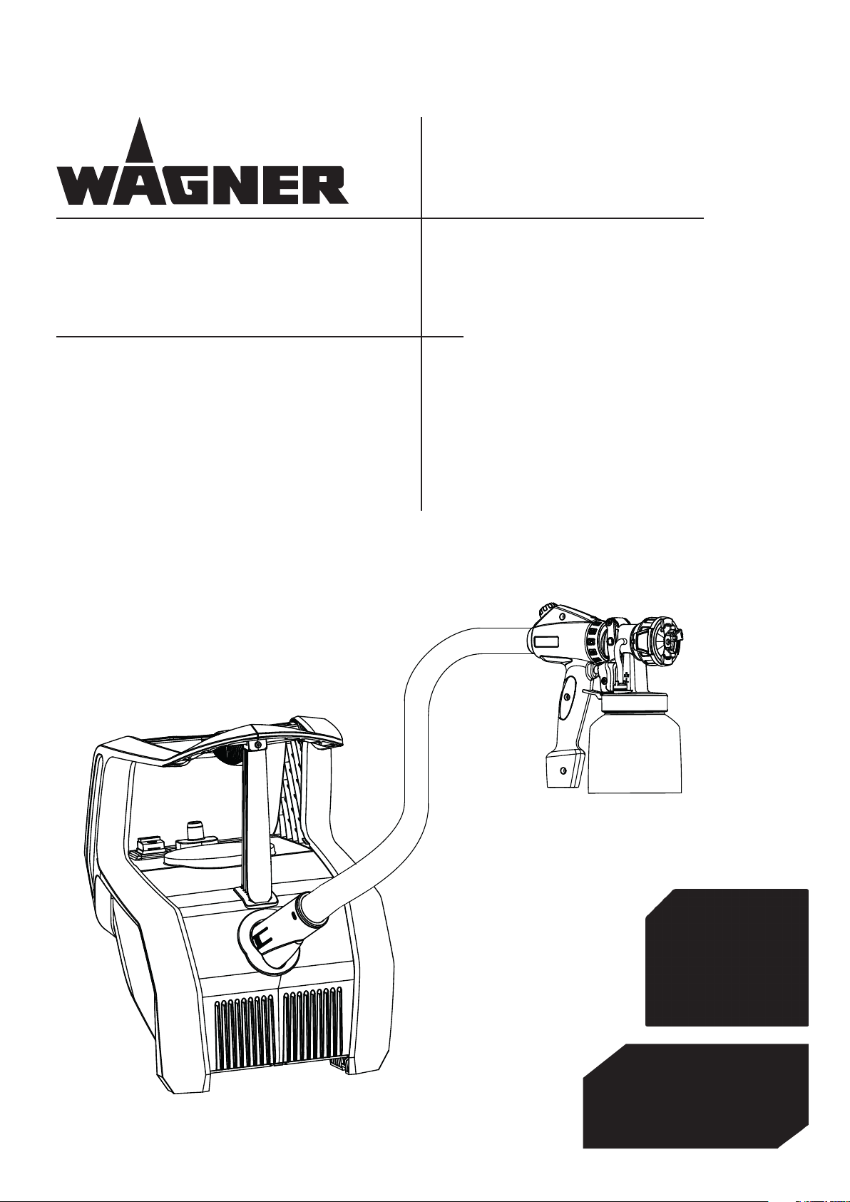
FinishControl 5000
- AUS- Operating manual 1
2339012
07/ 2014
Page 2
FinishControl 5000
24
18
19
20
21/22
23
8910 6
13
25
7
11
12
45
3
1
2
17
16
15
14
3.
1.1.
28
2.
26
27
1
A
B
A
Page 3
FinishControl 5000
1
1
1
A
1.
2.
B
3 – 20 cm
2
1.
2.
1
Page 4
FinishControl 5000
1
2
3
4 5
1
Page 5
FinishControl 5000
1
2
3
4
3
9
10
1
2
5
1
7
8
11
12
13
14
3456
2
6
7
Page 6
AUS
i
CONTENTS
Contents
FinishControl 5000
1 SAFETY REGULATIONS _______________________ 1
2 EXPLANATORY DIAGRAM _____________________ 3
3 THE WAGNER CLICK&PAINT SYSTEM ___________ 3
3.1 Disassembly of the spray gun ____________________3
4 TECHNICAL DATA ____________________________ 4
5 INTRODUCTION TO SPRAYING USING THE XVLP
PROCEDURE _________________________________ 4
6 COATING MATERIAL __________________________ 4
6.1 Coating Materials Suitable for Use _________________4
6.2 Coating Materials Not Suitable for Use _____________4
6.3 Coating materials that can only be processed with relevant spray attachment (accessories) ______________4
6.4 Preparing the coating material ____________________4
7 SETTING THE SPRAY GUN _____________________ 5
7.1 Setting the required spray pattern _________________5
7.2 Setting the amount of material ___________________5
7.3 Setting the amount of air ________________________5
7.4 Align the feed tube _____________________________5
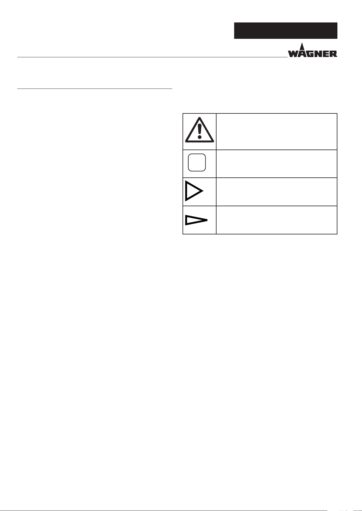
Explanation of symbols used
This symbol indicates a potential danger
for you or for the device.
Under this symbol you can nd important
information on how to
avoid injuries and damage to the device.
Indicates tips for use and other particularly
useful information.
Wide spray jet setting
Narrow spray jet setting
8 STARTING OPERATION _______________________ 5
9 SPRAYING TECHNIQUE _______________________ 5
10 BREAKS IN WORK ____________________________ 6
11 TRANSPORTATION ___________________________ 6
12 TAKING OUT OF OPERATION AND CLEANING ___ 6
12.1 Assembly _____________________________________6
13 MAINTENANCE ______________________________ 7
13.1 Air lter ______________________________________7
13.2 Air relief valve _________________________________7
14 CORRECTION OF MALFUNCTIONS _____________ 8
15 ACCESSORIES AND SPARE PARTS ______________ 9
15.1 Accessories ___________________________________9
15.2 Spare parts FinishControl ________________________9
15.3 Spare Parts FineSpray spray attachment ____________9
Testing of the unit ________________________________ 11
Note on disposal _________________________________ 11
Important information on product liability ____________ 11
Guarantee declaration _____________________________ 11
Wagner warranty policy ____________________________ 13
Service network __________________________________ 14
Page 7

FinishControl 5000
AUS
SAFETY REGULATIONS
1 SAFETY REGULATIONS
All local safety regulations in force must be observed.
Read the operating instructions carefully and follow the instructions laid down in them in order to avoid risks.
1. Safety at the workplace
a) Keep your workplace clean and well lit.
Disorder or unlit workplaces may result in accidents.
b) Never use the tool in hazardous areas that contain
ammable liquids, gases or dusts. Power tools
generate sparks that can ignite the dust or vapors.
c) Keep children and other persons away when using
the power tool. You can lose control of the tool if you are
distracted.
2. Electrical Safety
a) The tool plug must t into the socket. The plug may
not be modied in any form. Do not use adaptor
plugs together with protective-earthed tools.
Unmodied plugs and suitable sockets reduce the risk of
an electric shock.
b) Avoid physical contact with earthed surfaces such
as pipes, heating elements, stoves and refrigerators.
The risk through electric shock increases if your body is
earthed.
c) Keep the equipment away from rain and moisture.
The risk of an electric shock increases if water penetrates
electrical equipment.
b) Wear personal safety equipment and always wear
safety goggles. Wearing personal protective equipment,
such as dust mask, non-slip safety shoes, safety helmet
or ear protection, depending on the type of power tools,
reduces the risk of injury.
c) Avoid accidental starting-up. Ensure that the switch
is in the “OFF” position before inserting the plug
into the socket. Accidents can occur if you carry the
power tool while your nger is on the switch or if you
connect the power tool to the power supply which it is on.
d) Remove setting tools or wrenches before switching
on the power tool. A tool or wrench that is in a rotating
tool part can lead to injuries.
e) Avoid an unnatural posture. This ensures that you can
control the tool better in unexpected situations.
f) Wear suitable clothing. Do not wear wide clothing or
jewellery. Keep your hair, clothes and gloves away
from moving parts. Loose clothing, jewellery or long hair
can be caught in moving parts.
g) This appliance is not intended for use by persons
(including children) with reduced physical, sensory
or mental capabilities, or lack of experience
and knowledge, unless they have been given
supervision or instruction concerning use of the
appliance by a person responsible for their safety.
Children should be supervised to ensure that they do not
play with the appliance.
4. Careful Handling and Use of Power Tools
a) Do not overload the tool. Use the power tool
designed for the work that you are doing. You work
better and safer in the specied performance range if you
use the suitable power tool.
d) Do not misuse the mains lead by carrying the tool
by the lead, hanging it from the lead or by pulling
on the lead to remove the plug. Keep the lead away
from heat, oil, sharp edges or moving tool parts.
Damaged or twisted leads increase the risk of an electric
shock.
e) If you work outdoors with a power tool, only use
extension cables suitable for outdoor use. The use of
an extension lead that is suitable for outdoors reduces the
risk of an electric shock.
f) ) If you cannot avoid using the tool in a damp
environment, use a residual current operated
circuit-breaker. Using a residual current operated circuit-
breaker avoids the risk of electric shock.
3. Safety of Persons
a) Be attentive. Pay attention to what you are doing
and work sensibly with a power tool. Do not use the
tool if you are tired or under the inuence of drugs,
alcohol or medication. Just a moment of inattentiveness
while using the tool can lead to serious injuries.
b) Do not use power tools whose switch is defective. A
power tool that cannot be switched on or o is dangerous
and has to be repaired.
c) Remove the plug from the socket before carrying
out tool settings, changing accessories or putting
the tool away. This precautionary measure prevents
unintentional starting of the tool.
d) Store unused power tools so that they are
inaccessible to children. Do not let persons use the
tool who are not familiar with it or who have not
read these instructions. Power tools are dangerous
when they are used by inexperienced persons.
e) Take proper care of your tools. Check whether the
moving parts function trouble-free and do not jam,
whether parts are broken or damaged so that the
tool function is impaired. Have damaged parts repaired
before using the tool. Many accidents have their origin in
power tools that have been maintained badly.
f) Use the power tool, accessories, insert tools, etc. in
accordance with these instructions and in a fashion
specied for this special tool type. Take the working
conditions and the activity to be carried out into
consideration. The use of power tools for purposes other
than the intended ones can lead to dangerous situations.
1
Page 8

AUS
SAFETY REGULATIONS
FinishControl 5000
5. Service
a) Have your tool repaired only by qualied specialist
personnel and only with original spare parts. This
ensures that the tool safety is maintained.
b) If the supply cord is damaged, it must be replaced
by the manufacturer or it’s service agent or a
similarly qualied person in order to avoid a safety
hazard.
Safety instructions for colour application
devices
1. Risks of Fire and Explosion
Combustible gases develop in the work area
when spraying coating substances and due to the
autonomous formation of coating substances and
solvent vapors (danger zone).
Risk of re and explosion due to ignition sources in
this danger zone.
The electrically operated spray device contains
potential ignition sources (spark formation when
switching the motor on and o, when inserting and
removing the power plug, due to potential static
electricity at the spray gun)
-> Device must not be used at operating sites that fall
under the explosion protection ordinance.
-> Basic unit and mains connection must be located
outside the danger zone.
-> Do not use combustible coating substances and
cleaning agents -> observe product data sheets!
->Always seal paint or solvent containers tightly in
the vicinity of the device.
-> No ignition sources such as open re, lit tobacco
products, glowing wires, hot surfaces, sparks e.g. due
to angle grinders etc. must be present.
-> When cleaning the device with solvent do not spray
into a container with a small opening (bung hole).
Danger due to formation of an explosive gas/air
mixture.
The container into which you are spraying must be
earthed.
2. Warning: Danger of injury!
Never point spray gun at yourself, other persons or
animals.
3.
Wear breathing equipment when spraying.
The user should be supplied with a breathing mask. In order
to avoid occupational diseases, the working instructions
provided by the manufacturer of the materials, solvents
and cleaning agents used must be complied with during
preparation, working with and cleaning the equipment.
Protective clothing, gloves and, if necessary, protective skin
cream is required to protect the skin.
4.
Warning: When working with the paint spraying
system, both indoors and outdoors, care should
be taken that no solvent vapours are driven to the
motor-operated blower or that no solvent containing
vapours form in the area around the paint spraying
system. Place the motor-operated blower on the
opposite side to the object to be sprayed. When
working outdoors take wind direction into account.
When working in closed places a sucient ventilation
must be ensured to remove the solvent vapours. The
distance from the motor – operated blower to the
object to be sprayed must be at least 3 m.
5. Warning: The device is not splash proof. It should not
be used, neither outdoors in the rain nor be sprayed
with water nor immersed in liquid. Do not use the
device in damp or wet environments.
6. The units may only be used with a functional valve. If
paints rises in the ventilating hose (Fig. 1, item 17) do
not operate the unit further! Dismantle and clean the
ventilating hose, valve and diaphragm and replace the
diaphragm if necessary.
7. Do not lay the lled spray gun down.
8. Extraction systems should be installed on-site according to
the local regulations.
9. The object to be coated must be earthed.
10. Caution against dangers that can arise from the sprayed
substance and observe the text and information on the
containers or the specications given by the substance
manufacturer.
11. Do not spray any liquid of unknown hazard potential.
12. Before dismounting the spray attachment, relieve
pressure by opening the container.
13. Before working on the device, remove the power plug
from the socket.
14. Work or repairs on the electrical equipment should only
be carried out by a professional electrician, even if there
are instructions regarding such work in the operating
instructions. No liability will be accepted for improper
installation.
15. Do not sit or stand on the device. Danger of tilting/
breaking!
2
Page 9

FinishControl 5000
POS.
DESIGNATION
POS.
DESIGNATION
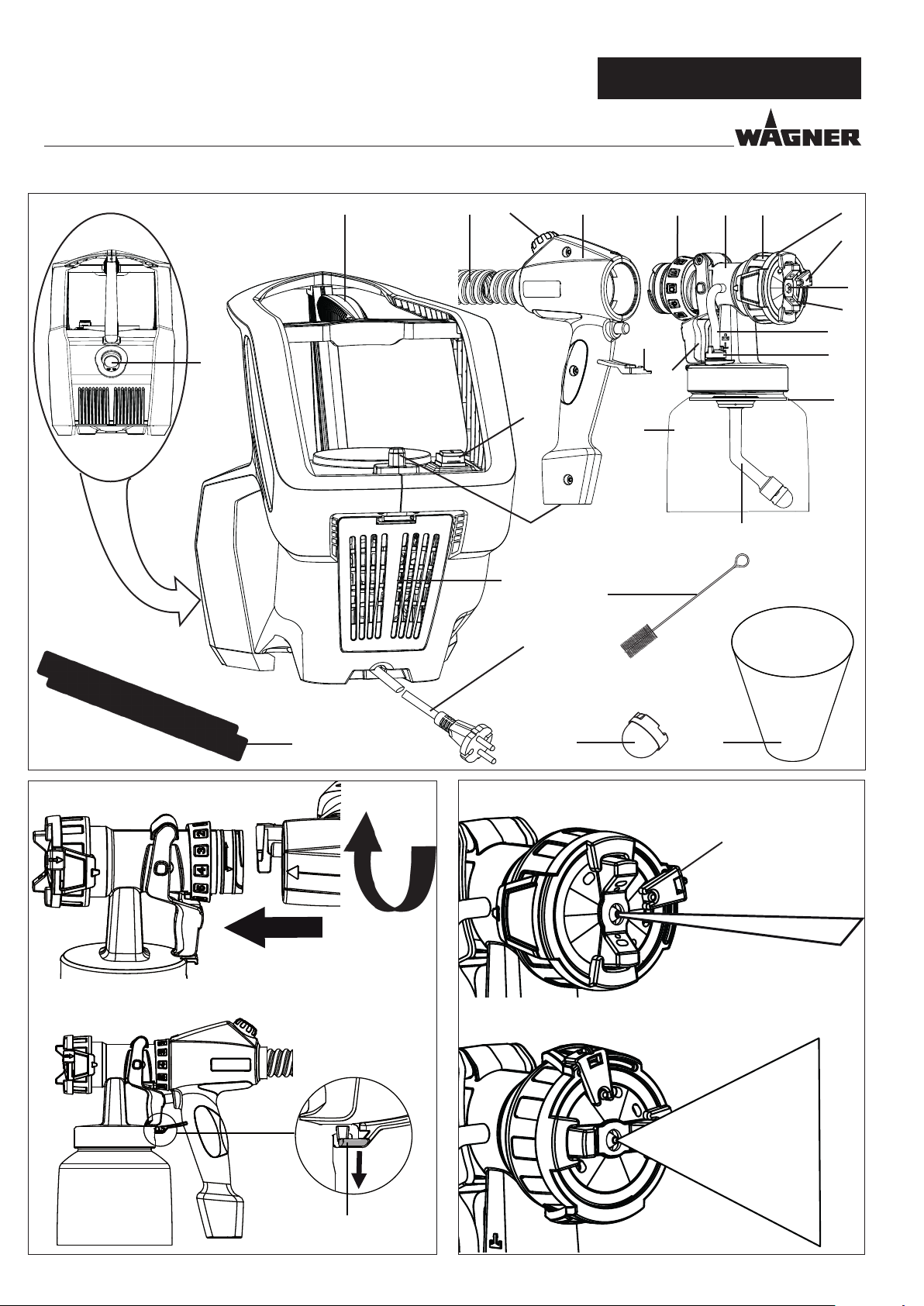
2 EXPLANATORY DIAGRAM FIG. 1
AUS
EXPLANATORY DIAGRAM/ CLICK&PAINT SYSTEM
1 Nozzle
2 Air cap
3 Spray jet width adjusting lever (shaping air)
4 Spray jet level adjusting ring (vertical/horizontal)
5 Union nut
6 Spray attachment complete
7 Material volume regulation
8 Gun handle
9 Air volume control
10 Air hose
11 Click&Paint catch
12
Trigger (actuates turbine starting switch
conveyed)
13 Container
14 Suction tube
material is
15 Container seal
16 Valve
17 Ventilating hose
18 Carry handle
19 ON/OFF switch (I = ON, 0 = OFF)
20 Gun mounting for park position
21 Air lter cover
22 Air lter
23 Power cable
24 Air hose connection
25 Cleaning brush
26 Fine feed tube lter (red)
Coarse feed tube lter (white)
27 Funnel (3 pcs.)
28 Air hose xing straps (2 pcs.)
3 THE WAGNER CLICK&PAINT SYSTEM
With the Wagner Click&Paint System, the front part of the gun (spray attachment) can be replaced quickly and easily.
This enables a rapid material change without cleaning, and ensures that the right tool is available for every material and application.
The following spray attachments are available:
Spray attachment Area of application
StandardSpray (yellow)
Order No. 2321 879
FineSpray (brown)
Order No. 2321 877
WallSpray (white)
Order No. 2321 880
3.1 DISASSEMBLY OF THE SPRAY GUN
For assembly, insert the spray attachment into the gun handle so that the two arrows point at each other. Turn the gun handle
90° in the arrow direction until it audibly engages. (Fig. 2)
To remove the spray attachment, push the catch (Fig. 2, A) beneath the trigger down and turn the spray attachment by 90°.
Spray attachment with slit nozzle and 1000 ml stainless steel container. Processes all standard
paints.
Spray attachment with round nozzle and 1000 ml stainless steel container. Ideal for low-viscosity
paints and glazes.
Interior wall paint spray attachment with slit nozzle and 1400 ml plastic container. Designed for
processing acrylic paints.
3
Page 10

AUS
TECHNICAL DATA/ INTRODUCTION/ PREPARING THE COATING MATERIAL
FinishControl 5000
4 TECHNICAL DATA
Voltage: 240 V~, 50 Hz
Power consumption: 1500 W
Atomizing output: 300 W
Container volume: 1000 ml
Air hose: 5 m
Power cable: 4 m
Protection class: I
Sound pressure level:*
Uncertainty K:
Sound pressure output:*
Uncertainty K:
Oscillation level:
Uncertainty K:
Weight (motor-operated blower,
air hose and spray gun): 8 kg
* The acoustic emission value was ascertained in accordance
with EN 50144-2-7:2000
84 dB (A)
4 dB (A)
97 dB (A)
4 dB (A)
<2.5 m/s²
1.5 m/s²
5 INTRODUCTION TO SPRAYING
USING THE XVLP PROCEDURE
XVLP (Extra Volume Low Pressure) is a low pressure spraying
technique, which works with a high volume of air and a low air
pressure. The greatest advantage of this spraying technique
is the low paint mist formation. This reduces the amount required to cover the object to a minimum.
As opposed to conventional application of coatings, this
method achieves a highly economical and perfect surface
quality and is, at the same time, environmentally friendly.
Function description
The paint spraying system consists of a motor-operated turbo-blower, which provides the spray gun with atomisation air
through an air hose.
In the spray gun, a part of the atomisation air is used to pressurise the container. This pressure causes the coating material
to be fed through the uptake pipe to the nozzle where it is
atomised by the rest of the atomisation air.
All settings necessary for operation (e.g. material volume) can
be conveniently made, directly on the gun.
6 COATING MATERIAL
6.1 COATING MATERIALS SUITABLE FOR USE
Solvent-based and water-soluble lacquer paints
Mordants, glazes, stains, oils, clear varnishes, synthetic enamels, coloured paints, alkyd resin varnishes, primers, radiator
paints, hammer eect enamels, anti-rust paints, special-eect
paints, textured paints
6.2 COATING MATERIALS NOT SUITABLE FOR USE
Materials that contain highly abrasive components, facade
paint, caustic solutions and acidic coating substances.
Flammable materials.
6.3 COATING MATERIALS THAT CAN ONLY BE
PROCESSED WITH RELEVANT SPRAY
ATTACHMENT ACCESSORIES
WallSpray Attachment: Interior wall paint (acrylic paints)
6.4 PREPARING THE COATING MATERIAL
Observe the manufacturer’s instructions for the
use of the coating material on the paint tin or on
the technical instruction sheet.
Coating material purity:
An absolute pre-condition for the trouble-free operation of
the ne-spray system is that the coating material is uncontaminated. If you have doubts as to the purity of the coating
material, we recommend that you rst lter it through a ne
sieve.
Processing the coating material with the FineSpray spray
attachment (brown)
Coating Material Processing Comments
Solvent-based lacquer paints
Water-soluble lacquer paints
Mordants, glazes,
stains, oils
Clear varnishes, synthetic enamels, coloured paints, alkyd
resin varnishes
observe manufacturer’s instructions
observe manufacturer’s instructions
undiluted
observe manufacturer’s instructions
Primers, radiator
paints, hammer effect enamels
observe manufacturer’s instructions
4
Page 11

FinishControl 5000
AUS
SETTING THE SPRAY GUN /STARTING OPERATION/
SPRAYING TECHNIQUE
Anti-rust paints, special-eect paints
Multicolor paints,
textured paints
observe manufacturer’s instructions
observe manufacturer’s instructions
WallSpray spray
attachment
(white) recommended
7 SETTING THE SPRAY GUN
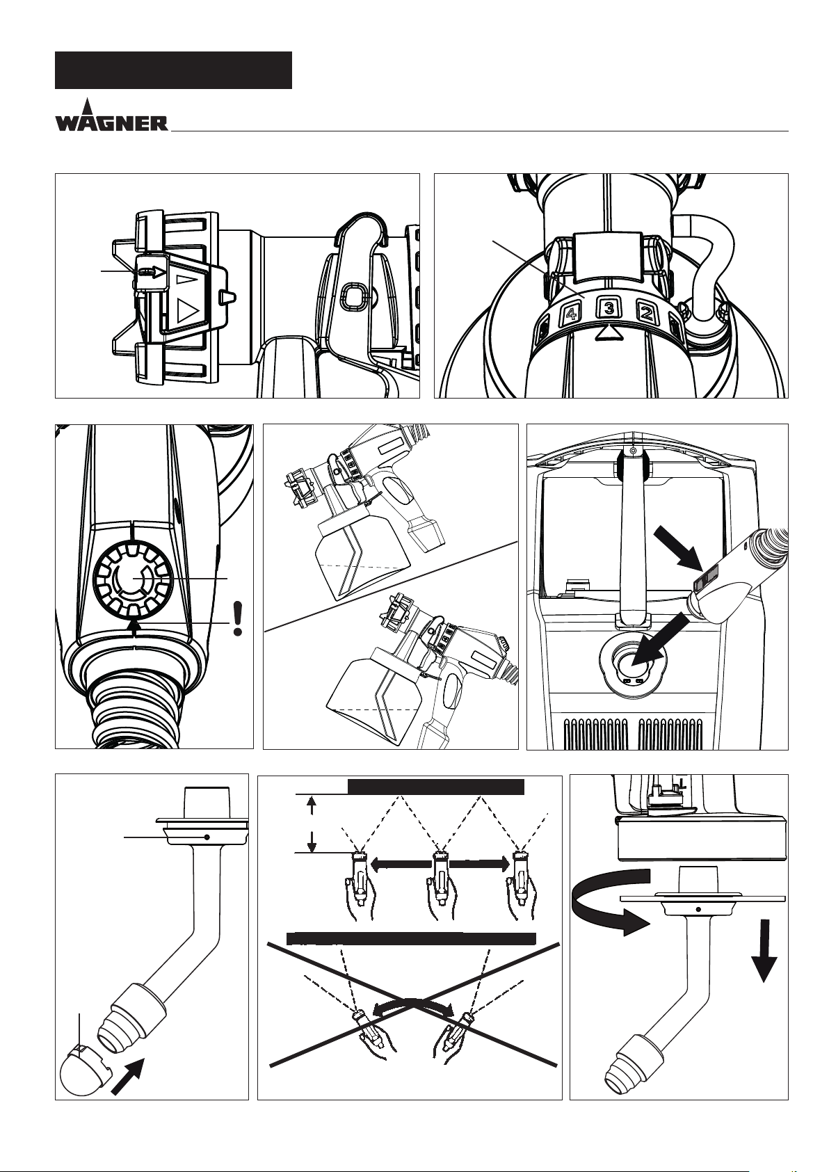
7.1 SETTING THE REQUIRED SPRAY PATTERN
Attention:
Never pull trigger while adjusting the air
cap settings.
The alignment of the spray jet can be determined by turning
the black adjusting ring (Fig. 3, 1).
A horizontal at jet
B vertical at jet
It is also possible to switch between a wide ( ) and a compact
( ) spray jet with the adjusting lever (Fig. 4, 1).
for vertical surfaces
for horizontal surfaces
8 STARTING OPERATION
Before connecting to the mains supply make sure that the
mains voltage corresponds to the operating voltage on the
rating plate. The unit must be connected with a properly
earthed shockproof socket.
1.
Squeeze the side clips together and insert the air hose onto
the basic unit. (Fig. 8)
2. Unscrew the container from the spray attachment.
3. Pour in the prepared coating material.
Fill the container
with maximum
1000 ml.
4.
Fit the appropriate lter to the feed tube depending on the
coating material used (Fig. 9, 1)
Low-viscosity coating materials
Viscous coating materials
5. Screw the container rmly onto the spray attachment.
6. Connect spray attachment and gun handle. (Fig. 2)
7. Plug in the power cable.
Switch on the main switch at the device.
8.
The device is now ready for operation.
1000ml
Fine lter (red)
Coarse lter (white)
7.2 SETTING THE AMOUNT OF MATERIAL FIG. 5)
The material volume can be adjusted incrementally from 1
(minimum) to 12 (maximum) by turning the material volume
control (Fig. 5, 1).
7.3 SETTING THE AMOUNT OF AIR FIG. 6
Turn the air volume control (Fig, 6, 1) clockwise to increase the
air volume or anti-clockwise to reduce the air volume (note
arrow on body of gun).
The correct setting of air and material volume is
crucial for atomisation and paint mist formation.
7.4 ALIGN THE FEED TUBE
If the feed tube is positioned correctly, the container
contents can be sprayed without almost any residue.
When working on lying objects:
Turn the feed tube forwards. (Fig. 7 A)
Spraying work when working on overhead objects:
Turn the feed tube rearwards. (Fig. 7 B)
9 SPRAYING TECHNIQUE
The FinishControl has a trigger with 2 pressure
points. In the rst stage the turbine is started. If
the trigger is pressed further, the material is trans-
ported.
Operate trigger on the spray gun.
Test spray a piece of cardboard to ensure correct setting of the
spray pattern, spray jet width, material and air volume.
Hold the paint spray gun upright and maintain a constant
distance of about 3 - 20 cm to the object being sprayed. (Fig.
10)
Move the paint spray gun evenly either from side to side or up
and down. If the gun is moved evenly, it will produce an even
surface nish.
Always start spraying away from the object and avoid stop-ping
spraying whilst still on the object.
In case of excessive paint mist formation, adjust the air and
material ow respectively and alter the distance from the
object.
5
Page 12

AUS
BREAKS IN WORK/ TRANSPORTATION/
TAKING OUT OF OPERATION AND CLEANING
FinishControl 5000
10 BREAKS IN WORK
1. Switch device o with main switch on the basic unit.
2. Insert spray gun into gun mounting on the device.
In using quick-drying or two-component coating
materials, do not fail to rinse unit through with
a suitable cleaning agent during the processing
period.
Important: The application life of the material can
change as a result of heating. Therefore, please
consult the material manufacturer.
11 TRANSPORTATION
1. Coil power cable around the basic unit.
2. Insert spray gun into gun mounting on the device.
3. Disconnect air hose by pressing the two side clips (Fig. 8).
4. Roll up the air hose and tie up with the xing straps.
12 TAKING OUT OF OPERATION AND
CLEANING
CAUTION! Never clean seals, diaphragm
and nozzle or air holes of the spray gun
with metal objects.
The ventilation hose and diaphragm are
only solvent-resistant to a limited extent.
Do not immerse in solvent, only wipe.
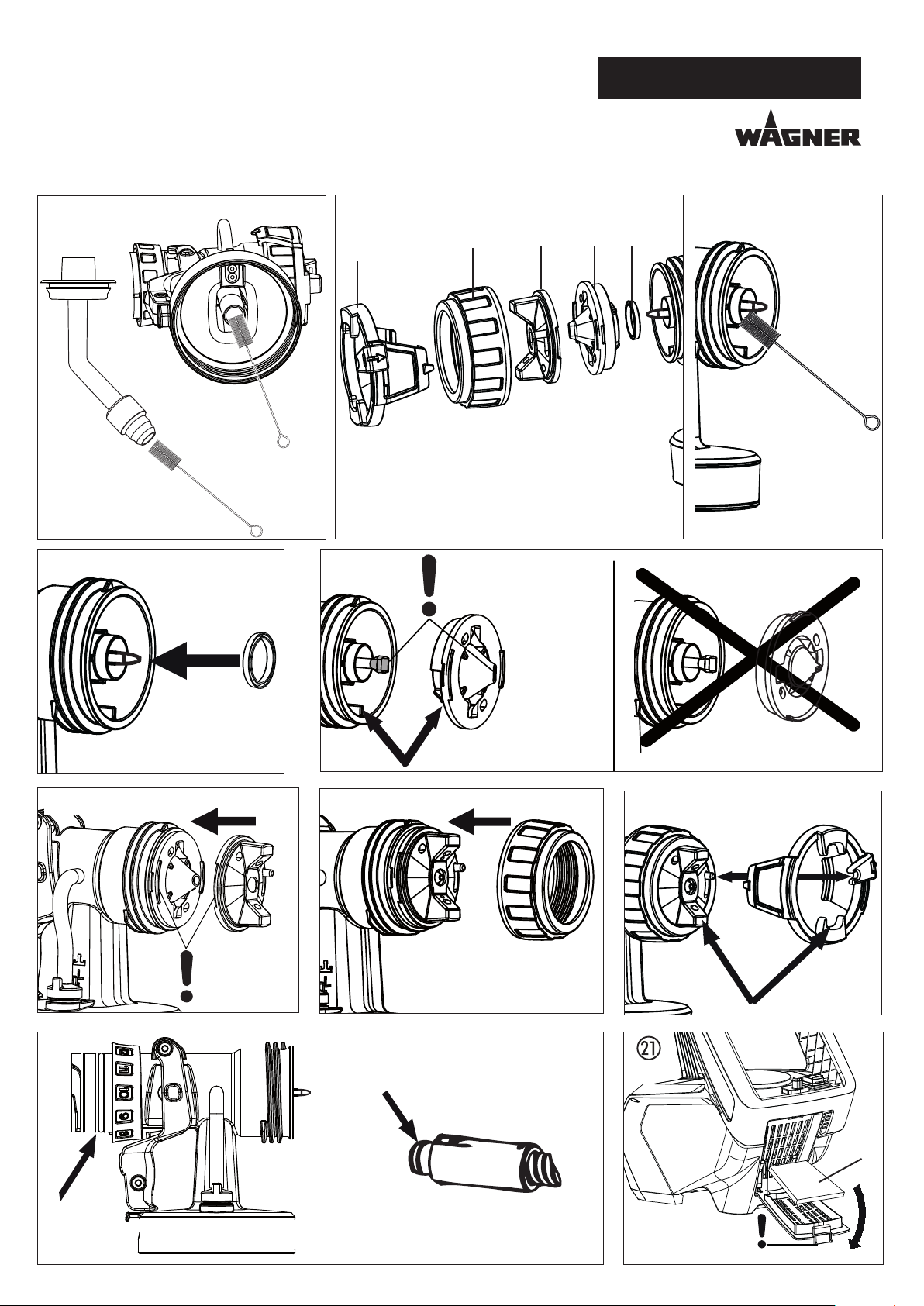
11.
Remove the adjusting ring (fig. 13,1) carefully from
the union nut (2). Unscrew union nut (2), remove
air cap (3), nozzle (4) and nozzle seal (5).
Thoroughly clean all parts.
Take special care when cleaning the interstices on
the needle (Fig. 14)
Clean the outside of the spray gun and container with a
12.
cloth soaked in solvent or water.
13. Assemble the parts again (see “Assembly”).
12.1 ASSEMBLY
ATTENTION! Follow the steps described
below exactly for assembly. Otherwise
the spray attachment may be damaged.
1. Turn the machine o.
2. Divide the spray gun. Press catch (Fig. 2, A) down slightly.
Twist spray attachment and gun handle towards each
other.
ATTENTION! Electrical contacts in gun
handle. Never hold the gun handle under
water or immerse it into liquids.
Clean the housing only with a moistened
cloth.
3. Unscrew the container.
Empty the remaining coating material into the original
container.
4.
Pre-clean the container and feed tube using a
brush and suitable cleaning agent.
Clean the ventilating bore. (Fig. 9, 2)
5.
Pour solvent or water into the container. Screw the
container back on.
Do not use flammable materials for cleaning
purposes.
6. Connect spray attachment and gun handle. (Fig. 2)
7. Switch device on and ush spray attachment through with
solvent or water.
Repeat the above procedure until the solvent or water
emerging from the nozzle is clear.
8. Turn o the machine and divide the spray gun.
9.
Screw o the container and empty it.
Unscrew feed tube with container seal. (Fig. 11)
10.
Clean feed tube and suction nozzle in spray attachment
with cleaning brush. (Fig. 12)
1. Push nozzle seal onto the needle so that the groove (slot)
points away from the spray attachment. (Fig. 15)
2.
Place nozzle on the needle with recess downwards.
Attention if using WallSpray or StandardSpray:
Position of needle must be congruent with the nozzle
aperture. (Fig. 16)
3. Place air cap on nozzle (pay attention to recesses in the air
cap). (Fig. 17)
4. Screw on union nut. (Fig. 18)
5.
Snap the adjusting ring into the union nut. (Fig. 19)
Make sure that the two recesses on the adjusting ring
are engaged in the air cap clamps and that the lever for
adjusting the spray jet width is located on the pin.
6. Place the container seal from below on the feed tube and
slide it over the collar, while turning the container seal
slightly.
7. Screw the feed tube with the container seal into the body
of the gun.
In order to mount the gun more easily apply
lubricating grease (enclosed) liberally to the O-ring
at the spray attachment and to the O-ring of the
plug connection of the air hose (Fig. 20).
6
Page 13

FinishControl 5000
13 MAINTENANCE
13.1 AIR FILTER
Attention! Never operate the device with
the air lter soiled or missing, as dirt could
be sucked up and aect the operation of
the device.
Always check the air lter before starting
work.
1. Unplug the power plug.
2. Open the cover of the air lter compartment (Fig. 21).
3.
Clean (blow out) or replace the air filter (Fig. 21,1)
depending on the degree of soiling.
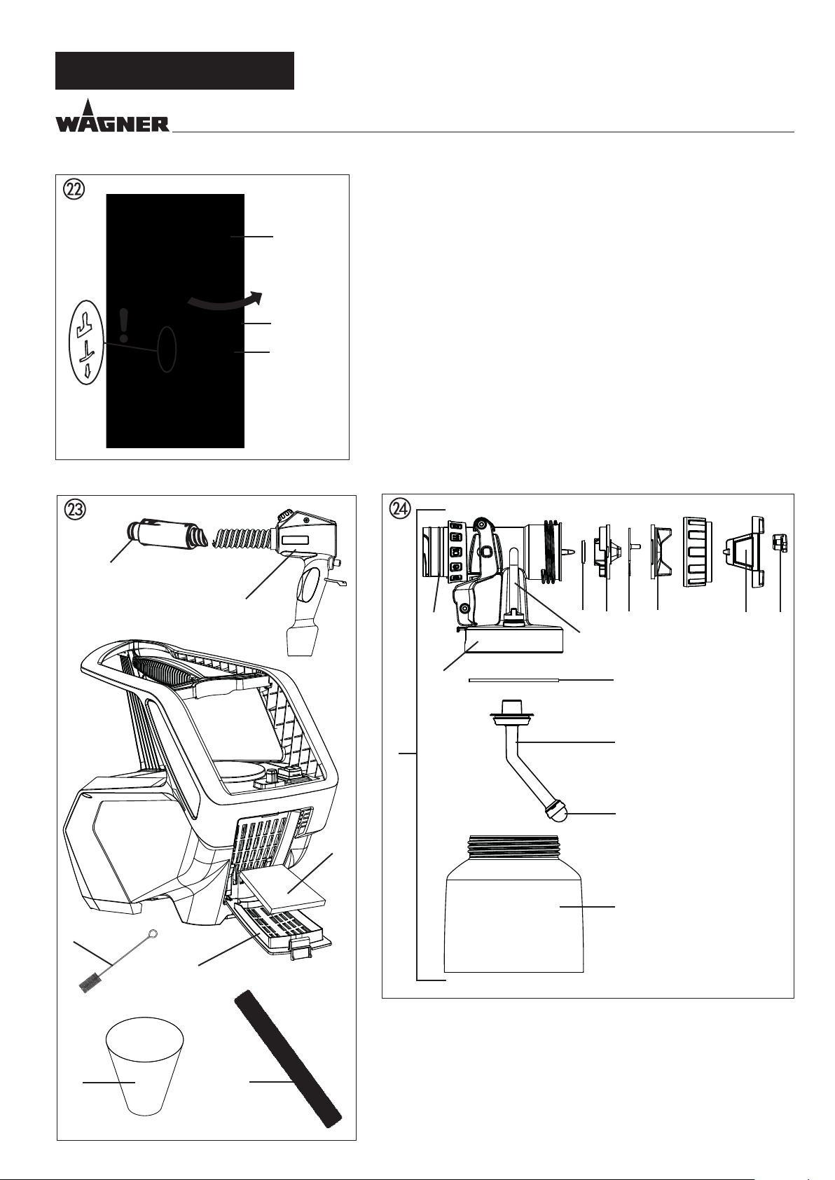
13.2 AIR RELIEF VALVE
If paint has entered the ventilation hose, proceed
as follows:
AUS
MAINTENANCE
1. Pull the ventilating hose (Fig. 22, 1) at the top from the
gun body. Screw o the valve cover (2). Remove the
diaphragm (3). Clean all the parts carefully.
CAUTION! The ventilation hose and
diaphragm are only solvent-resistant to a
limited extent. Do not immerse in solvent,
only wipe.
2. Place the diaphragm in the valve cover with the pin facing
forward (Also see the marking on the gun body).
3. Turn the body of the gun upside down and screw on the
valve cover from underneath.
Place the ventilating hose on the valve cover and on the
4.
nipple at the gun body.
7
Page 14

AUS
CORRECTION OF MALFUNCTIONS
14 CORRECTION OF MALFUNCTIONS
MALFUNCTION CAUSE REMEDY
FinishControl 5000
The unit will not start
No coating material emerges
from the nozzle
Coating material drips from the
nozzle
Atomisation too coarse
Spray jet pulsates
Coating material causes “paint
tears
Excessive paint mist (overspray)• Distance to the object too large
Paint in the ventilating hose
No mains voltage
•
Device overheated
•
Nozzle clogged
•
Material volume setting too low
•
Paint container seal damaged
•
No pressure build-up in container
•
Container empty
•
Ventilation hose loose/damaged
•
Feed tube loose
•
Feed tube / feed tube lter clogged
•
Air vent on feed tube blocked
•
Diaphragm stuck
•
Air cap, nozzle or needle soiled
•
Spray attachment incorrectly
•
assembled
Nozzle loose
•
Nozzle seal worn
•
Nozzle worn
•
Needle worn
•
Material volume too large
•
Nozzle contaminated
•
Viscosity of coating material too high
•
Too little pressure build-up in
•
container
Air lter heavily soiled
•
Amount of air too low
•
Air hose damaged
•
Coating material in container running
•
out
Nozzle seal worn
•
Air lter heavily soiled
•
Feed tube loose
•
Feed tube / feed tube lter clogged
•
Too much coating material applied
•
Distance too small
•
Incorrect spray attachment
•
Too much coating material applied
•
Amount of air too high
•
Coating substance over-diluted
•
Incorrect spray attachment
•
Diaphragm soiled
•
Diaphragm defective
•
Check
•
Unplug the power plug, let the device cool
•
down approx. 30 minutes, do not bend the
hose, check the air lter, do not cover the intake
slots
Clean
•
Increase volume
•
Replace
•
Tighten container
•
Rell
•
Insert or replace
•
Insert
•
Clean or use another lter
•
Clean
•
Remove and clean (see section 13.2)
•
Clean
•
Assemble correctly (see section 12.1)
•
Tighten Union nut
•
Change
•
Change
•
Use new spray attachment
•
Reduce volume
•
Clean
•
Dilute further
•
Tighten container
•
Change (see section 13.1)
•
Increase volume
•
Check and replace if necessary
•
Rell
•
Replace
•
Change (see section 13.1)
•
Insert
•
Clean or use another lter
•
Reduce volume
•
Increase distance
•
Use another spray attachment
•
Reduce distance
•
Reduce volume
•
Reduce volume
•
Reduce degree of dilution
•
Use another spray attachment
•
Clean the diaphragm (see section 13.2)
•
Replace the diaphragm (see section 13.2)
•
8
Page 15

FinishControl 5000
15 ACCESSORIES AND SPARE PARTS
15.1 ACCESSORIES
AUS
ACCESSORIES AND SPARE PARTS
POS.
1 2321 879 StandardSpray spray attachment (yellow) (with 1000 ml container)
2 2321 877 FineSpray spray attachment (brown) (with 1000 ml container)
3 2321 880 WallSpray spray attachment (white) (with 1400 ml container)
4
15.2 SPARE PARTS FINISHCONTROL 5000 FIG. 23
POS.
1 2312 650 Cover of air lter compartment
2 2322 446 Air lter (3 pcs.)
3 2314 573 Gun handle with air hose
4 0420 316 O-ring of air hose
5 0514 209 Cleaning brush
6 2324 745 Funnel (3 pcs.)
ORDER NO.
2324 749
ORDER NO.
DESIGNATION
Processes all standard paints.
Ideal for low-viscosity paints and glazes.
Designed for processing acrylics.
Container with cover (1400 ml)
DESIGNATION
7 2324 751 Air hose xing strap
15.3 SPARE PARTS FINESPRAY SPRAY ATTACHMENT BROWN FIG. 24
POS.
1 2321 877 FineSpray spray attachment (brown) (with 1000 ml container)
2
3 2314 591 Spray jet adjustment ring
4
5
6
7
8
9
10
11
12
ORDER NO.
2321 868
2332 579
2317 820
2314 585
2317 667
2323 934
2304 027
0417 308
2326 126
2319 223
DESIGNATION
Spray jet width adjusting lever
Union nut (brown)
Air cap
Air screen
Nozzle (R 1.8)
Nozzle seal
Ventilating hose, valve cover, diaphragm
O-ring of spray attachment
Body of gun (including position 8-10)
Container seal
13
2319 222
Feed tube
9
Page 16

AUS
SPARE PARTS AND ACCESSORIES
FinishControl 5000
POS.
14
15
ORDER NO.
2324 248
2324 249
2322 451
2315 539
DESIGNATION
Fine feed tube lter (red, 5 pc.)
Coarse feed tube lter (white, 5 pc.)
Container with cover 1000 ml
Lubricating grease
10
Page 17

FinishControl 5000
AUS
TESTING OF THE UNIT / INFORMATION ON PRODUCT LIABILITY / GUARANTEE DECLARATION
TESTING OF THE UNIT
For safety reasons, we would recommend having the device
checked by an expert as required but at least every 12 months
to ensure that it can continue to operate safely.
In the case of unused devices, the check can be postponed
until they are next started up.
All (potentially deviating) national inspection and maintenance regulations must also be observed.
If you have any questions, please contact the customer service
team at Wagner.
IMPORTANT INFORMATION ON PRODUCT LIABILITY
An EU directive valid since 01.01.1990 species that the manufacturer is only liable for his products if all the parts originate
from the manufacturer or are approved by him, and if the units
are mounted and operated properly.
If accessories or spare parts from third parties are used, liability
can be partially or completely inapplicable. In extreme cases
the responsible authorities can prohibit the use of the entire
unit (German industrial employer‘s liability insurance association and factory inspectorate).
GUARANTEE DECLARATION
(Status 01.02.2009)
1. Scope of guarantee
All Wagner professional colour application devices (hereafter referred to as products) are carefully inspected,
tested and are subject to strict checks under Wagner
quality assurance. Wagner exclusively issues extended
guarantees to commercial or professional users (hereafter
referred to as “customer”) who have purchased the product in an authorised specialist shop, and which relate to
the products listed for that customer on the Internet under
www.wagner-group.com/pro-guarantee.
The buyer’s claim for liability for defects from the purchase
agreement with the seller as well as statutory rights are not
impaired by this guarantee.
We provide a guarantee in that we decide whether to replace
or repair the product or individual parts, or take the device
back and reimburse the purchase price. The costs for materials
and working hours are our responsibility. Replaced products
or parts become our property.
2. Guarantee period and registration
With original WAGNER accessories and spare parts, compliance with all safety regulations is guaranteed.
NOTE ON DISPOSAL
In observance of the European Directive 2002/96/EC on waste
electrical and electronic equipment and implementation in
accordance with national law, this product is not to be disposed of together with household waste material but must be
recycled in an environmentally friendly way!
The guarantee period amounts to 36 months. For industrial
use or equal wear, such as shift operations in particular, or in
the event of rentals it amounts to 12 months.
Systems driven by petrol or air are also guaranteed for a 12
month period.
The guarantee period begins with the day of delivery by the
authorised specialist shop. The date on the original purchase
document is authoritative.
For all products bought in authorised specialist shops from
01.02.2009 the guarantee period is extended to 24 months
providing the buyer of these devices registers in accordance
with the following conditions within 4 weeks of the day of delivery by the authorised specialist shop.
Registration can be completed on the Internet under
www.wagner-group.com/pro-guarantee.
The guarantee certicate is valid as conrmation, as is the
original purchase document that carries the date of the purchase. Registration is only possible if the buyer is in agreement
with having the data being stored that is entered during registration.
When services are carried out under guarantee the guarantee
period for the product is neither extended nor renewed.
Once the guarantee period has expired, claims made against
the guarantee or from the guarantee can no longer be enforced.
11
Page 18

AUS
GUARANTEE DECLARATION
FinishControl 5000
3. Handling
If defects can be seen in the materials, processing or performance of the device during the guarantee period, guarantee
claims must be made immediately, or at the latest within a
period of 2 weeks.
The authorised specialist shop that delivered the device is entitled to accept guarantee claims. Guarantee claims may also be
made to the service centres named in our operating instructions. The product has to be sent without charge or presented
together with the original purchase document that includes
details of the purchase date and the name of the product. In
order to claim for an extension to the guarantee, the guarantee certicate must be included.
The costs as well as the risk of loss or damage to the product
in transit or by the centre that accepts the guarantee claims
or who delivers the repaired product, are the responsibility of
the customer.
4. Exclusion of guarantee
Guarantee claims cannot be considered
for parts that are subject to wear and tear due to use or other
-
natural wear and tear, as well as defects in the product that
are a result of natural wear and tear, or wear and tear due
to use. This includes in particular cables, valves, packaging,
jets, cylinders, pistons, means-carrying housing components,
lters, pipes, seals, rotors, stators, etc. Damage due to wear and
tear that is caused in particular by sanded coating materials,
such as dispersions, plaster, putty, adhesives, glazes, quartz
foundation.
in the event of errors in devices that are due to non-compliance
-
with the operating instructions, unsuitable or unprofessional
use, incorrect assembly and/or commissioning by the buyer
or by a third party, or utilisation other than is intended,
abnormal ambient conditions, unsuitable coating materials,
unsuitable operating conditions, operation with the incorrect
mains voltage supply/frequency, over-operation or defective
servicing or care and/or cleaning.
for errors in the device that have been caused by using
-
accessory parts, additional components or spare parts that
are not original Wagner parts.
for products to which modications or additions have been
-
carried out.
for products where the serial number has been removed or
-
is illegible
for products to which attempts at repairs have been carried
-
out by unauthorised persons.
for products with slight deviations from the target properties,
-
which are negligible with regard to the value and usability of
the device.
for products that have been partially or fully taken apart.
-
5. Additional regulations.
The above guarantees apply exclusively to products that have
been bought by authorised specialist shops in the EU, CIS,
Australia and are used within the reference country.
If the check shows that the case is not a guarantee case, repairs are carried out at the expense of the buyer.
The above regulations manage the legal relationship to us
concludingly. Additional claims, in particular for damages and
losses of any type, which occur as a result of the product or
its use, are excluded from the product liability act except with
regard to the area of application.
Claims for liability for defects to the specialist trader remain
unaected.
J. Wagner GmbH
Division Professional Finishing
Otto Lilienthal Strasse 18
88677 Markdorf
Federal Republic of Germany
Subject to modications
12
Page 19

FinishControl 5000
AUS
WAGNER WARRANTY POLICY
1st January 2012
WAGNER WARRANTY POLICY
Our goods come with guarantees that cannot be excluded under the Australian Consumer Law.
You are entitled to a replacement or refund for a major failure and for compensation for any other reasonably foreseeable loss or
damage. You are also entitled to have the goods repaired or replaced if the goods fail to be of acceptable quality and the failure
does not amount to a major failure.
This warranty is provided by WAGNER and is in addition to your rights under the Australian Consumer Law.
WAGNER products come with a warranty, from the date of proof of purchase, against any manufacturing faults and defects. The
warranty periods are as follows:
DIY Products 24 months
Semi-Professional Products DIY use 24 months
Semi-Professional use 12 months
Contractor and Commercial Products 36 months
PlastCoat Units 24 months
Hire and Rental Use 6 months
Where replacement goods are supplied, the warranty is limited to the term of the original purchase.
Warranty applies only to the original purchaser and is not transferable.
This warranty does not cover products which are damaged as a result of any of the following:
• Unsuitable or abnormal usage
• Incorrect commissioning or tting, removal or modication of any safety devices
• Repairs which are performed by unqualied or unauthorised persons, or do not involve genuine WAGNER parts
• Normal wear and tear
• Damaged in transport
• Faulty maintenance work, negligent handling, servicing or cleaning
• Unsuitable coating materials
To claim the warranty (Australia and New Zealand only) you should send or take your product (at your cost), with proof of purchase to one of the Authorised WAGNER Service Centres listed on the back of this Warranty. If found to be a warrantable claim,
WAGNER, through its Authorised Service Agents will either repair or replace the product at its option free of charge and advise
you when your replacement or repaired product is available for pick up by you.
Under this express Warranty Policy WAGNER is not liable for any loss or damage however arising as a result of the fault or defect
in the products.
This express Warranty is subject to the purchaser providing satisfactory proof of purchase within Australia or New Zealand of the
product to WAGNER or its Authorised Service Centres.
WAGNER reserves the right to perform any repairs in excess of those stated in our operating instructions.
Please note: This Warranty Policy and Procedure supersedes all other warranty policies, procedures and documentation for products sold within Australia and New Zealand.
AUSTRALIAN CUSTOMERS
Please send or take your product to any one of the Authorised WAGNER Service Centres listed on the reverse of this
form.
NEW ZEALAND CUSTOMERS
Contact the Master Distributor listed below for your nearest Authorised Service Centre:
Paintworx, 70 Lady Ruby Drive, East Tamaki NZ 1730 Telephone: (09) 271 2879
13
Page 20

AUS
AUSTRALIAN CAPITAL TERRITORY
Hume ACT Small Engines 02 6260 1828
Mitchell Paint Place 02 6241 7811
Fyshwick DRB Equipment Repairs 02 6239 1229
NEW SOUTH WALES
Rockhampton Nth Paint Place CQ 07 4928 2992
Scarborough Airless2You 0403 573 998
Tallai Sprayfix 0439 680 686
Townsville Airless & Pressure Cleaners 07 4725 8880
SOUTH AUSTRALIA
64 9 272 2840
AUTHORISED SERVICE CENTRES
FinishControl 5000
Bathurst David Catt Spray Repair 02 6332 3269
Coffs Harbour Brycker Hire 02 6652 1829
Forster Flashback Repairs 02 6555 7202
Georgetown Daynatech 02 4960 9400
Gladesville Colussi Engineering 02 9817 5433
Gosford West Gosford Power Tool Centre 02 4325 5322
Grafton South Beadman Engineering 02 6642 3047
Lake Cathie Coastal Spray 02 6585 4735
Lismore South Paint & Trade Supplies 02 6622 1147
Milperra Murphy’s Spray & Blast 02 9792 2653
Moorebank Spray Equipment Mobile 02 9822 4011
Moruya Moruya Mower & Chainsaw 02 4474 3322
Penrith Penrith Paint Specialists 02 4731 1178
Tamworth Tamworth Paint Centre 02 6762 0520
Wagga Wagga Simpson Machinery Service 02 6928 1353
Woollongong Frank Dean Airless Repairs 02 4296 2989
NORTHERN TERRITORY
Holtze Palmerston Paint Supplies 08 8932 7999
QUEENSLAND
Acacia Ridge Phillro Industries 07 3711 9589
Burpengary Glascraft 07 3888 0866
Cairns Cairns Wholesale Paint 07 4035 2000
Gladstone Earle’s Paint & Wallpaper 07 4972 3277
Kingaroy Earle’s Paint & Wallpaper 07 4162 5011
Maroochydore Suncoast Pressure Cleaners 07 5443 1139
Meadowbrook Logan ProSpray 07 3803 4276
Maryborough Earle’s Paint & Wallpaper 07 4121 5202
Milton Paint Place Superstore 07 3369 7206
Murarrie Access Industrial Products 07 3390 8199
Nerang W.A.S. 07 5596 7255
Noosaville Paint Place Noosa 07 5449 9964
Mount Gambier Attiwills Home & Industry 08 8725 6644
Lonsdale MWA 08 8294 6444
Wingfield Oliver Technologies 08 8262 2466
VICTORIA
Bairnsdale Bristol Decorator Centre 03 5153 1177
Bairnsdale Murphy’s World of Colour 03 5152 4148
Ballarat Bylsma Hire 03 5335 8397
Bayswater Spraylinks 03 9720 1710
Campbellfield Dete Australia 03 9359 6080
Dandenong Sth Paint Spot 03 9793 4599
Eltham Paint Place 03 9439 4900
Geelong Nth Kerr’s North Side 03 5278 6011
Hastings Dewtech 03 5979 1617
Oakleigh Sprayworld 03 9041 4473
Sebastopol Bylsma Hire 03 5335 8397
Shepparton Shepparton Paint Centre 03 5831 2522
Shepparton A1 Electric Motors 03 5831 7066
Wantirna South Morgan’s Paint Spot 03 9801 8011
Warrnambool Chemblast Industrial Coatings 03 5562 7636
TASMANIA
Derwent Park Paintech 03 6273 2755
Invermay Forward Mechanical Repairs 04 1736 5627
WESTERN AUSTRALIA
Bassendean Eden Systems 08 9379 3588
Welshpool All Spray 08 9358 1313
NEW ZEALAND
Contact Paintworx for nearest Service Centre
14
Wagner Spraytech Australia
14-16 Kevlar Close, Braeside, Victoria, 3195.
Customer Service 1800 924 637
Email: info@wagneraustralia.com.au
www.wagneraustralia.com.au
 Loading...