

titelseite_neu_a5.fm Seite 1 Donnerstag, 20. Oktober 2005 2:38 14
MagicLock
ML22, ML44
D 2 Zentralverriegelung
Montage- und Bedienungsanleitung
GB 10 UCentral locking system
Installation and Operating Manual
Inhaltsverzeichnis
Hinweise zur Benutzung der Einbauanleitung . . . . . . . . . . . . . . . . . . . . . . . . . . . . . . . . . . . 2
Zubehör. . . . . . . . . . . . . . . . . . . . . . . . . . . . . . . . . . . . . . . . . . . . . . . . . . . . . . . . . . . . . . . . . 2
Sicherheits- und Einbauhinweise . . . . . . . . . . . . . . . . . . . . . . . . . . . . . . . . . . . . . . . . . . . 3-4
Lieferumfang . . . . . . . . . . . . . . . . . . . . . . . . . . . . . . . . . . . . . . . . . . . . . . . . . . . . . . . . . . . . 4
Benötigtes Werkzeug . . . . . . . . . . . . . . . . . . . . . . . . . . . . . . . . . . . . . . . . . . . . . . . . . . . . . . 5
Einbau der Steuereinheiten . . . . . . . . . . . . . . . . . . . . . . . . . . . . . . . . . . . . . . . . . . . . . . . . . 6
Einstellung ZV-Gestänge an das Originalgestänge . . . . . . . . . . . . . . . . . . . . . . . . . . . . . . . 7
Schaltplan . . . . . . . . . . . . . . . . . . . . . . . . . . . . . . . . . . . . . . . . . . . . . . . . . . . . . . . . . . . . . . . 8
Bohrschablone . . . . . . . . . . . . . . . . . . . . . . . . . . . . . . . . . . . . . . . . . . . . . . . . . . . . . . . . . . . 9
Technische Daten . . . . . . . . . . . . . . . . . . . . . . . . . . . . . . . . . . . . . . . . . . . . . . . . . . . . . . . . . 9
Hinweise zur Benutzung der Einbauanleitung
2
Warnung! Sicherheitshinweis: Nichtbeachtung kann zu Personen- oder
Materialschäden führen.
Achtung! Sicherheitshinweis: Nichtbeachtung führt zu Materialschäden und
beeinträchtigt die Funktionen der ML-22/44.
u Die Raute kennzeichnet Einbauschritte, die Sie ausführen müssen.
Damit der Einbau ohne Schwierigkeiten stattfindet, diese Montage- und Bedienungsanleitung vor Beginn der Montage durchlesen.
Bei einem Besitzwechsel muss diese Montage- und Bedienungsanleitung mit übergeben
werden.
Bei allen Arbeiten sind die entsprechenden Herstellerangaben zu beachten. Bei Fahrzeugen mit Seitenairbags in den Türen sind die entsprechenden Herstellerangaben des
jeweiligen Fahrzeugherstellers zu beachten.
Produktbeschreibung Art.-Nr.
Zubehör
manual ml-22/44 29.06.2004 8:32 Uhr Seite 2
Universal Schiebetürkontakt (nur in Verbindung mit ML-11 montierbar) ML-10
Zentralverriegelung für eine zusätzliche Tür/Heckklappe
Fahrzeugspezifische Funk-Fernbedienung MT-150-WAECO2
ML-11
Sicherheits- und Einbauhinweise
Warnung! Unzureichende
Leitungsverbindungen können
zur Folge haben, dass durch
Kurzschluss:
- Kabelbrände entstehen
- der Airbag ausgelöst wird
- elektronische Steuerungseinrichtungen
beschädigt werden
- elektrische Funktionen (Blinker, Bremslicht, Hupe, Zündung, Licht) ausfallen
Beachten Sie deshalb folgende
Hinweise:
Bei Arbeiten an den Leitungen:
30 (Eingang von Batterie Plus direkt),
15 (Geschaltetes Plus, hinter Batterie)
31 (Rückleitung ab Batterie, Masse)
L (Blinkerleuchten Links)
R (Blinkerleuchten Rechts)
Die sicherste Verbindungsart ist, die
Kabelenden miteinander zu
verlöten
und anschließend zu isolieren.
Bei wiederlösbaren Verbindungen nur
isolierte Kabelschuhe, Stecker und
Flachsteckhülsen verwenden. Keine
Quetschverbinder (Leitungsverbinder)
oder Lüsterklemmen verwenden.
Zum Verbinden der Kabel mit Kabelschuhen, Stecker oder Flachsteckhülsen eine Krimpzange verwenden.
Bei Kabelanschlüssen an 31 (Masse):
Das Kabel mit Kabelschuh und Zahnscheibe an eine fahrzeugeigene Masseschraube schrauben oder mit Kabelschuh,
Blechschraube und Zahnscheibe an das
Karosserieblech schrauben.
Auf gute Masseübertragung achten!
Warnung! Wegen Kurzschlussgefahr vor Arbeiten an der Fahrzeugelektrik immer den Minuspol
der Batterie abklemmen. Bei Fahrzeugen mit Zusatzbatterie ebenfalls den Minuspol abklemmen.
Achtung! Beim Abklemmen des
Minuspols der Batterie verlieren
alle flüchtigen Speicher der
Komfort-Elektronik ihre gespeicherten Daten.
Folgende Daten müssen Sie je nach Fahrzeugausstattung neu eingeben:
Radiocode
Fahrzeuguhr
Zeitschaltuhr
Bordcomputer
Sitzposition
Hinweise zur Einstellung können Sie in der
jeweiligen Bedienungsanleitung nachlesen.
Warnung! Im Fahrzeug montierte
Teile der
MAGIC LOCK ML-22/44
müssen so befestigt werden, dass
sie sich unter keinen Umständen
(scharfes Abbremsen, Verkehrsunfall) lösen können und zu
Ver-
letzungen der Fahrzeuginsassen
führen können.
3
manual ml-22/44 29.06.2004 8:32 Uhr Seite 3
Für 2-türige Fahrzeuge
B 2 Steuereinheiten
D 1 Kabelbaum
E 2 Verbindungsstangen
F 2 Befestigungsklemmen
G 8 Blechschrauben
H 2 Lochschienen
I 4 Blechmuttern
J 2 Kabeldurchführungen
Für 4-türige Fahrzeuge
B 2 Steuereinheiten
C 2 Stelleinheiten
D 1 Kabelbaum
E 4 Verbindungsstangen
F 4 Befestigungsklemmen
G 16 Blechschrauben
H
4
Lochschienen
I 8 Blechmuttern
J 4 Kabeldurchführungen
H
E
F
B/C
I
G
Lieferumfang
Sicherheits- und Einbauhinweise
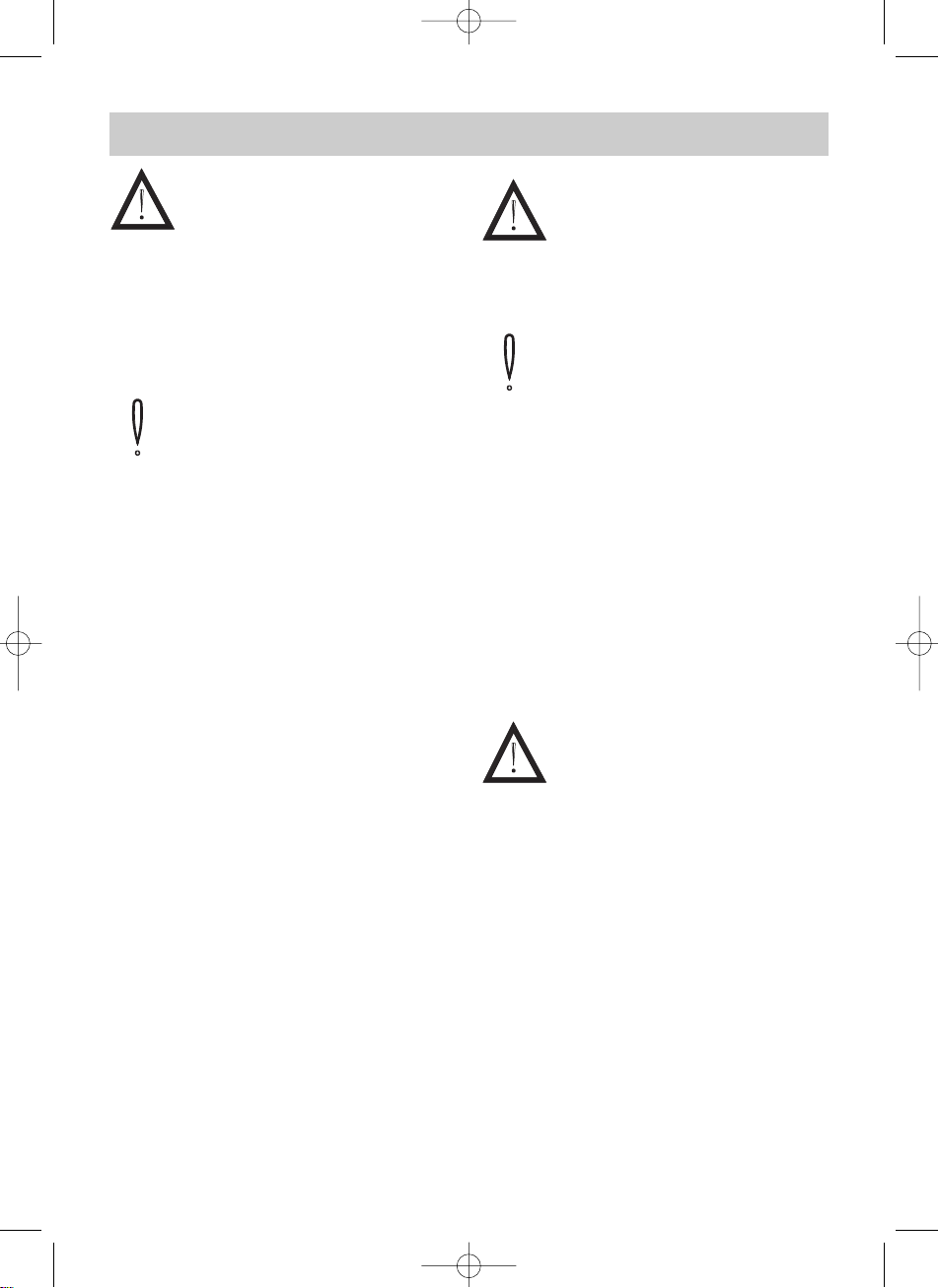
Achtung! Zum Prüfen der Spannung in elektrischen Leitungen
darf nur eine Diodenprüflampe
oder ein Voltmeter benutzt werden.
Prüflampen mit einem Leuchtkörper
nehmen zu hohe Ströme auf und
die Fahrzeugelektronik kann beschädigt werden.
Diodenprüflampe
Prüflampe
Achtung! Um Schäden zu vermeiden, auf
ausreichenden Freiraum für den Bohreraustritt
achten. Jede Bohrung entgraten und mit
Rostschutzmittel behandeln.
oder
Voltmeter
4
manual ml-22/44 29.06.2004 8:32 Uhr Seite 4
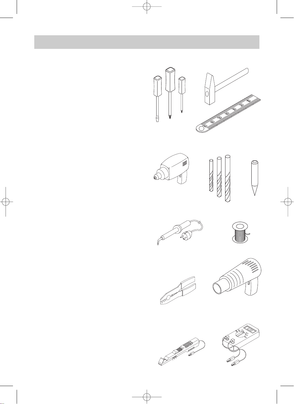
Benötigtes Werkzeug
Für Einbau und Montage
werden benötigt:
- Maßstab
- Körner
- Hammer
- Bohrer
- Bohrmaschine
- Schraubendreher
Für den elektrischen Anschluss
und Überprüfung wird benötigt:
- Diodenprüflampe oder Voltmeter
- Krimpzange
- Isolierband
- Wärmeschrumpfschlauch
- Heißluftföhn
- Lötkolben
- Lötzinn
Zur Befestigung von Empfänger und
Kabel benötigen Sie evtl. noch Schrauben, Blechschrauben und Kabelbinder.
Körner
Maßstab
Hammer
Schraubendrehersatz
Voltmeter
oder
Krimpzange
Diodenprüflampe
Bohrersatz
Bohrmaschine
Heißluftföhn
Lötkolben
Lot
5
manual ml-22/44 29.06.2004 8:32 Uhr Seite 5
Mechanischer Einbau
Beginnen Sie mit dem Einbau an der
Fahrertür. Handkurbel des Fensterhebers
und Armlehne abnehmen und die Türinnenverkleidung entfernen. Plastikfolie
vorsichtig von unten her lösen.
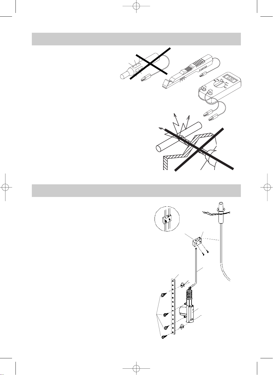
Eine günstige Position für die Steuereinheit
(B) in der Nähe der Verriegelungsstange
wählen, die den Verriegelungsknopf mit
dem Türschloss verbindet. Die Bewegungsrichtung von Steuereinheit und
Verriegelungsstange sollte möglichst
parallel und hintereinander verlaufen.
Ziehen Sie die Verbindungsstange (E)
durch das Auge der Steuereinheit und
biegen Sie diese so zurecht, dass sie sich
problemlos mit der Verriegelungsstange
verbinden läßt.
Steuereinheit mittels Bohrschablone
(Seite 9) oder mit einer der beiliegenden
Lochschienen (H) direkt am Türkörper
befestigen.
Bewegen Sie die Steuereinheit und den
Verriegelungsknopf in die Position „entriegelt“ und justieren Sie die Befestigungsklemmen (F) auf der Verbindungsstange (E)
gemäß Abbildungen Seite 4. Den Überstand der Stange abkneifen.
Achten Sie darauf, dass Fensterscheibe
und Mechanismus des Fensterhebers
beim Öffnen und Schließen nicht von der
Steuereinheit berührt werden.
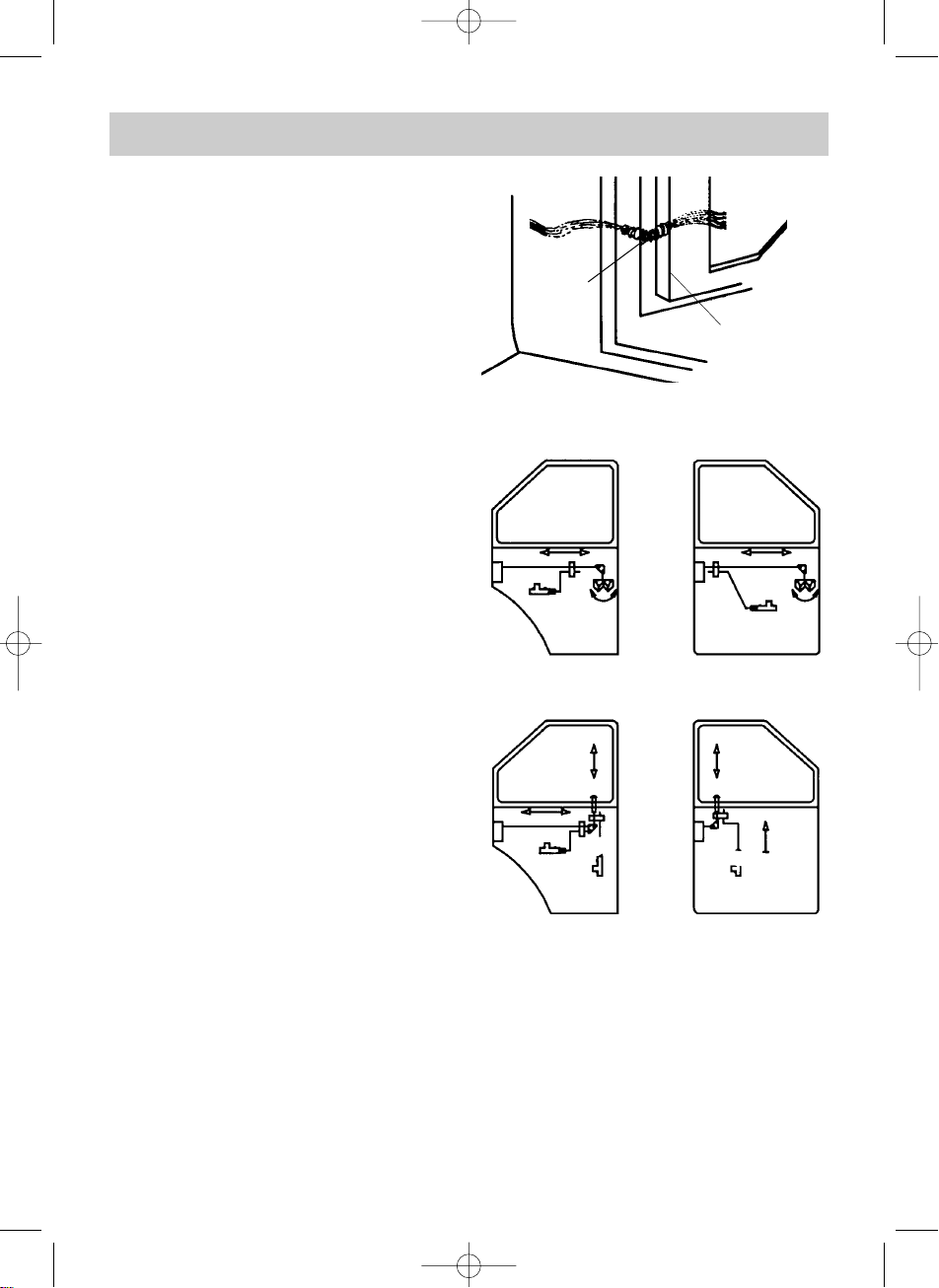
Falls an der Kopfseite der Tür keine Öffnung oder Bohrung vorhanden ist, ein
ca. 9 mm großes Loch bohren und die
Kabelführung aus Gummi (J) einsetzen
(siehe Abbildung 1).
J
Tür
1
2
1
2
vordere Tür
1 = verriegelt
2 = entriegelt
1.
hintere Tür
Einbau der Steuereinheiten
2.
3.
hinter
e Tür
1 =verriegelt
2 =entriegelt
12 12
vor
dere Tür
1
2
6
manual ml-22/44 29.06.2004 8:32 Uhr Seite 6

- Hub des Stellmotors einfahren, Originalgestänge auf „verriegeln“ stellen.
- Gestänge mit Klemmblock an das Originalgestänge befestigen.
Achtung! Genaue Einstellung beachten!
- Beim Ver- oder Entriegeln mit dem Türschlüssel muss der Stellmotor der Zentralver-
riegelung auf halbem Schlüsselweg die Zentralverriegelung aktivieren (siehe Abbildung).
- Gegebenenfalls die Einstellung des Betätigungsgestänges wiederholen.
Einstellung ZV-Gestänge an das Originalgestänge
1/2
1/2
7
manual ml-22/44 29.06.2004 8:32 Uhr Seite 7

Masse
GND
Anschlüsse Steuerrelais
1 = +12 V – rot
2 = Steuerleitung ZV „zu“ – braun
3 = Motorleitung ZV „auf“ – blau
4 = Ext. Steuerung +12 V = ZV „auf“
5 = Ext. Steuerung -12 V = ZV „auf“
6 = -12 V – schwarz
7 = Steuerleitung ZV „auf“ – weiß
8 = Motorleitung ZV „zu“ – grün
9 = Ext. Steuerung +12 V = ZV „zu“
10 = Ext. Steuerung -12 V = ZV „zu“
-12 V
Schaltplan
bl = blau
gr = grün
br = braun
w = weiß
sc = schwarz
ro = rot
8
manual ml-22/44 29.06.2004 8:32 Uhr Seite 8

Bohrschablone
Bohrung Ø 5 mm
Bohrung Ø 5 mm
Betriebsspannung 12 V
Str
omaufnahme
ML-22 max. 10 A
ML-44 max. 15 A
Technische Daten
9
manual ml-22/44 29.06.2004 8:32 Uhr Seite 9

Contents
Information for using the installation instructions
Warning! Safety precaution: Failure to observe this warning may result in
injury to persons or damage to material.
Caution! Safety precaution: Failure to observe this warning will result in
damage to material and affect the proper
functioning of magic lock ML-22/44.
u This symbol indicates installation steps which have to be carried out.
To ensure problem-free fitting, read these installation and operating instructions carefully
before starting work.
When changing the owner the installation and operating instructions must be presented.
Please pay attention to all according producer dates while working.
For cars with side-airbags built in the seats, detection for occupied and childrenseats
please take note of the corresponding information of each manufacturer.
Product description Ref. No.
Accessories
manual ml-22/44 29.06.2004 8:32 Uhr Seite 12
Information for using the installation instructions . . . . . . . . . . . . . . . . . . . . . . . . . . . . . . . .10
Accessories. . . . . . . . . . . . . . . . . . . . . . . . . . . . . . . . . . . . . . . . . . . . . . . . . . . . . . . . . . . . . 10
Safety and installation instructions . . . . . . . . . . . . . . . . . . . . . . . . . . . . . . . . . . . . . . . . . . . 11
Scope of delivery. . . . . . . . . . . . . . . . . . . . . . . . . . . . . . . . . . . . . . . . . . . . . . . . . . . . . . . . . 12
Tools required . . . . . . . . . . . . . . . . . . . . . . . . . . . . . . . . . . . . . . . . . . . . . . . . . . . . . . . . . . . 13
Installation of the control unit . . . . . . . . . . . . . . . . . . . . . . . . . . . . . . . . . . . . . . . . . . . . . . . 14
Adjustment central locking rod to original rod . . . . . . . . . . . . . . . . . . . . . . . . . . . . . . . . . . . 15
Wiring diagram . . . . . . . . . . . . . . . . . . . . . . . . . . . . . . . . . . . . . . . . . . . . . . . . . . . . . . . . . . 16
Drill template. . . . . . . . . . . . . . . . . . . . . . . . . . . . . . . . . . . . . . . . . . . . . . . . . . . . . . . . . . . . 17
Technical data. . . . . . . . . . . . . . . . . . . . . . . . . . . . . . . . . . . . . . . . . . . . . . . . . . . . . . . . . . . 17
Universal contact for sliding doors (can be fitted only in conjunction with ML-11) ML-10
Central locking system for one additional door/tailgate ML-11
Radio r
10
emote conr
ols for specifi
c vehicles
MT-150-WAECO2

Safety and installation instructions
Warning! Improper cable
connections may result in
short circuits which can cause:
- cable fires
- triggering of the airbag
- damage to electronic control equipment
- failure of electrical functions (blinkers,
brake lights, horn, ignition, lights).
Please note the following:
For working on the cables, the following
terminal designations are used:
30 (input from battery plus direct)
15 (switched plus, behind battery)
31 (return cable from battery, neutral)
L Blinker left
R Blinker right
The securest form of connection is by
soldering the cable ends and then
insulating the connection.
For releasable connections, use only
insulated cable brackets, connector
plugs and tabs. Do not use lustre
terminals. For connecting the cables
with cable brackets, plugs or tabs,
use crimping pliers.
For cable connections to 31 (earth):
Attach the cable with a bracket and
toothed washer to an earthing screw on
the vehicle or screw it onto the metalwork
of the vehicle using a bracket, metal screw
and toothed washer.
Always ensure a good earthing connection!
Warning! Because of the risk of
short circuits, always disconnect
the negative pole of the battery
before starting work. At vehicles
with a supplementary battery, also
disconnect this negative pole.
Caution! On disconnecting the
negative pole of the battery, all
the volatile memories of the
convenience electronics will
lose their stored data.
Depending on the vehicle’s equipment,
the following date may have to be
reprogrammed:
Radio code
Clock
Timer
Board computer
Seat position
Instructions on how to reset these can
be found in the relevant operating
instructions.
Warning! The components of
the
MAGIC LOCK ML-22/44
manual ml-22/44 29.06.2004 8:32 Uhr Seite 13
which are inside the vehicle must
be securely fixed so that they
cannot come loose and
the vehicle’s occupants
any circumstances (emergency
braking, traffic accident).
injure
under
11

Safety and installation instructions
Caution! To check the voltage in
electric cables, use only a diode
test lamp or a voltmeter. Test
lamps which light up take too
much current and the vehicle
electronics may be damaged.
Diode testlamp
Testlamp
or
manual ml-22/44 29.06.2004 8:32 Uhr Seite 14
Caution! To avoid damage, always ensure
that there is enough clearance for the drill bit
to emerge. Every drill hole must be deburred
and treated with a rust proofing agent.
Scope of delivery
For 2-door vehicles
B 2 Control units
D 1 Cable harness
E 2 Connecting rods
F 2 Fastening clips
G 8 Sheet metal screws
H 2 Rails with punched holes
I 4 Fastening nuts
J 2 Cable conducts
Voltmeter
F
For 4-door vehicles
B 2 Control units
C 2 Servo units
D 1 Cable harness
E 4 Connecting rods
F 4 Fastening clips
G 16 Sheet metal screws
H
4
Rails with punched holes
I 8 Fastening nuts
J 4 Cable conducts
12
H
E
I
B/C
G

Tools required
The following are required
for installation:
- Measure
- Prick punch
- Hammer
- Drill bits
- Drill
- Screwdrivers
The following are required for the
electrical connections and testing:
- Diode test lamp or voltmeter
- Crimping pliers
- Insulation tape
- Heat shrinkable tubing
- Hot blow drier
- Soldering iron
- Solder
For securing the receiver and
cables, you may also need bolts,
metal screws and cable binders.
Prick
punch
Measure
Hammer
Set of screwdrivers
Voltmeter
or
Crimping
pliers
Diode testlamp
Set of drill
bits
Drill
Hot
blow dri-
Soldering
iron
Solder
manual ml-22/44 29.06.2004 8:32 Uhr Seite 15
13

Mechanical installation
Commence installation on the driver’s
door. Remove the crank handle of the
window winder and the arm rest and
remove the inside panelling of the door.
Remove the plastic foil carefully from
the bottom.
Choose a favourable position for the
control unit (B) close to the locking rod
which connects the locking button to the
door lock. The direction of movement of
the control unit and the locking rod should
be as parallel as possible and in tandem.
Pull the connecting rod (E) through the
eye of the control unit and bend it so
as to provide easy connection with the
locking bar.
Attach the control unit directly to the door
by means of a drill template (page 9) or
one of the enclosed rails with punched
holes (H). Move the control unit and the
locking button into ”unlocked” position
and adjust the fastening clips (F) on the
connecting rod (E) according figures on
page 4 and pinch off the excess part of
the rod.
Pay attention that the window pane and
the winder mechanism do not come
in contact with the control unit during
opening and closing.
If the head of the door has no hole or
opening in it, drill a hole with approx. 9 mm
diameter and insert the rubber cable.
J
door
1
2
1
2
front door
1 = locked
2 = unlocked
1.
rear door
Installation of the control unit
2.
3.
r
ear door
1 =locked
2 =unlocked
12 12
fr
ont door
1
2
manual ml-22/44 29.06.2004 8:32 Uhr Seite 16
14

- Retract the lifting part of the servomotor, position the original rod to ”lock”.
- Fasten the rod to the original rod by means of a clamp.
Attention! Pay attention to a precise setting
- When the door is locked or unlocked with the door key, the servomotor should actuate
the central locking system at half course of the key (see diagram).
- Repeat the setting of the connecting rod if necessary.
Adjustment central locking rod to original rod
manual ml-22/44 29.06.2004 8:32 Uhr Seite 17
1/2
1/2
15

Masse
GND
-12 V
Wiring diagram
manual ml-22/44 29.06.2004 8:32 Uhr Seite 18
bl = blue
gr = gree
br = brown
w = white
sc = black
ro = red
Electrical connection external control
1 = +12 V – red
2 = control cable CL ”close” – brown
3 = motor cable CL ”open” – blue
4 = exeternal control +12 V = ZV ”open”
5 = exeternal control GND (-) = ZV ”open”
6 = GND – black
7 = control cable CL ”close” – withe
8 = motor cable CL ”close” – green
9 = exeternal control +12 V = ZV ”close”
10 = exeternal control GND (-) = ZV ”close”
16

Drill template
hole Ø 5 mm
hole Ø 5 mm
Operating voltage 12 V
Input curr
ent
ML-22 max. 10 A
ML-44 max. 15 A
Technical data
manual ml-22/44 29.06.2004 8:32 Uhr Seite 19
17

manual ml-22/44 29.06.2004 8:32 Uhr Seite 19

manual ml-22/44 29.06.2004 8:32 Uhr Seite 19

adresse_A5_05.fm Seite 2 Mittwoch, 21. September 2005 3:46 15
Headquarters
WAECO International GmbH · Hollefeldstraße 63 · D-48282 Emsdetten
D
Fon: +49 2572 879-195 · Fax: +49 2572 879-322 · E-Mail: info@waeco.de · Internet: www.waeco.de
Europe
WAECO Schweiz AG
CH
Riedackerstrasse 7a
CH-8153 Rümlang (Zürich)
Fon: +41 44 8187171
Fax: +41 44 8187191
E-Mail: info@waeco.ch
WAECO Danmark A/S
DK
Tværvej 2
DK-6640 Lunderskov
Fon: +45 75585966
Fax: +45 75586307
E-Mail: waeco@waeco.dk
WAECO Ibérica S.A.
E
Camí del Mig, 106
Poligono Industrial Les Corts
E-08349 Cabrera de Mar
(Barcelona)
Fon: +34 93 7502277
Fax: +34 93 7500552
E-Mail: info@waeco.es
WAECO Distribution SARL
F
ZAC 2 · Les Portes de L‘Oise
Rue Isaac Newton – BP 59
F-60230 Chambly (France)
Fon: +33 1 30282020
Fax: +33 1 30282010
E-Mail: info@waeco.fr
WAECO Finland OY
FIN
Mestarintie 4
FIN-01730 Vantaa
Fon: +358 20 7413220
Fax: +358 9 7593700
E-Mail: waeco@waeco.fi
www.waeco.com
WAECO Italcold SRL
I
Via dell’Industria 4/0
I-40012 Calderara di Reno (BO)
Fon: +39 051 727094
Fax: +39 051 727687
E-Mail: sales@waeco.it
WAECO Norge AS
N
Leif Weldingsvei 16
N-3208 Sandefjord
Fon: +47 33428450
Fax: +47 33428459
E-Mail: firmapost@waeco.no
WAECO Benelux B.V.
NL
Ecustraat 3
NL-4879 NP Etten-Leur
Fon: +31 76 5029000
Fax: +31 76 5029090
E-Mail: verkoop@waeco.nl
WAECO Svenska AB
S
Gustaf Melins gata 7
S-42131 Västra Frölunda
(Göteborg)
Fon: +46 31 7341100
Fax: +46 31 7341101
E-Mail: info@waeco.se
WAECO UK Ltd.
UK
Dorset DT2 8LY · Unit G
Roman Hill Business Park
UK-Broadmayne
Fon: +44 1305 854000
Fax: +44 1305 854288
E-Mail: sales@waeco.co.uk
Overseas + Middle East
WAECO Pacific Pty. Ltd.
AUS
1 John Duncan Court
Varsity Lakes QLD 4227
Fon: +61 7 55076000
Fax: +61 7 55221003
E-Mail: sales@waeco.com.au
WAECO Impex Ltd.
HK
Headquarters
Suites 3210-12 · 32/F · Tower 2
The Gateway · 25 Canton Road
Tsim Sha Tsui · Kowloon
Hong Kong
Fon: +852 2 4632750
Fax: +8 52 24639067
E-Mail: info@waeco.com.hk
WAECO Impex Ltd.
ROC
Taipei Office
2 FL-3 · No. 56 Tunhua South Rd, Sec 2
Taipei 106, Taiwan
Fon: +886 2 27014090
Fax: +886 2 27060119
E-Mail: marketing@waeco.com.tw
WAECO Middle East FZCO
UAE
R/A 8, SD 6
Jebel Ali, Dubai
Fon: +971 4 8833858
Fax: +971 4 8833868
E-Mail: waeco@emirates.net.ae
WAECO USA, Inc.
USA
8 Heritage Park Road
Clinton, CT 06413
Fon: +1 860 6644911
Fax: +1 860 6644912
E-Mail: customercare@waecousa.com
4445100036 10/2005
 Loading...