

Waeco MagicComfort MSH200 Installation And Operating Instructions Manual

MagicComfort MSH200
DE 7 Nachrüstbare Einbau-Sitzheizung
Montage- und Bedienungsanleitung
EN 17 Retrofit insert seat heater
Installation and Operating
Instructions
FR 27 Chauffage de siège,
montage ultérieur
Instructions de montage et de
service
ES 37 Calefacción del asiento como
equipamiento adicional
Instrucciones de montaje y de
servicio
IT 48 Riscaldamento sedili addizionale
Istruzioni di montaggio e d’uso
NL 58 In te bouwen stoelverwarming
Montage- en bedieningshandleiding
DA 68 Sædevarme til eftermontering
Monterings- og betjeningsvejledning
SV 78 Sätesvärmare för inbyggnad
Monterings- och bruksanvisning
NO 88 Ettermonterbar setevarmer
Monterings- og bruksanvisning
FI 98 Jälkikäteen asennettava
istuinlämmitys
Asennus- ja käyttöohje
MagicComfort MSH200
1 2 3
4
9
6
8
5
7
10 11
12
13 14
15
1
2
MagicComfort MSH200
2
3
1
1
2
2
3
5
6
4
4
30 –
35 cm
6
5
3

MagicComfort MSH200
987
ba0
dedcgf
4

MagicComfort MSH200
h
blsw
5 A
+12 V (15)
or
120 A A
+12 V (30)
rt
sw
sw
bl
DE EN FR ES IT NL DA SV NO FI
BL Blau Blue Bleu Azul Blu Blauw Blå Blå Blå Sininen
OR Orange Orange Orange Naranja Arancione Oranje Orange Orange Oransje Oranssi
RT Rot Red Rouge Rojo Rosso Rood Rød Röd Rød Punainen
SW Schwarz Black Noir Negro Nero Zwart Sort Svart Svart Musta
(31)
5

MagicComfort MSH200
i
j
1
2
k
ca. 24 mm
6

MagicComfort MSH200 Hinweise zur Benutzung der Anleitung
Bitte lesen Sie diese Anleitung vor der Inbetriebnahme sorgfältig durch
und bewahren Sie sie auf. Geben Sie sie im Falle einer Weitergabe des
Gerätes an den Nutzer weiter.
Inhaltsverzeichnis
1 Hinweise zur Benutzung der Anleitung . . . . . . . . . . . . . . . . . . . . . . . 7
2 Sicherheits- und Einbauhinweise. . . . . . . . . . . . . . . . . . . . . . . . . . . . 8
3 Lieferumfang . . . . . . . . . . . . . . . . . . . . . . . . . . . . . . . . . . . . . . . . . . 10
4 Bestimmungsgemäßer Gebrauch . . . . . . . . . . . . . . . . . . . . . . . . . . 11
5 Technische Beschreibung . . . . . . . . . . . . . . . . . . . . . . . . . . . . . . . . 11
6 Sitzheizung montieren . . . . . . . . . . . . . . . . . . . . . . . . . . . . . . . . . . . 11
7 Sitzheizung benutzen. . . . . . . . . . . . . . . . . . . . . . . . . . . . . . . . . . . . 15
8 Gewährleistung . . . . . . . . . . . . . . . . . . . . . . . . . . . . . . . . . . . . . . . . 15
9 Entsorgung. . . . . . . . . . . . . . . . . . . . . . . . . . . . . . . . . . . . . . . . . . . . 15
10 Technische Daten . . . . . . . . . . . . . . . . . . . . . . . . . . . . . . . . . . . . . . 16
1 Hinweise zur Benutzung der Anleitung
WARNUNG!
Sicherheitshinweis: Nichtbeachtung kann zu Tod oder schwerer
!
A
Verletzung führen.
ACHTUNG!
Nichtbeachtung kann zu Materialschäden führen und die Funktion
des Produktes beeinträchtigen.
HINWEIS
Ergänzende Informationen zur Bedienung des Produktes.
I
➤ Handlung: Dieses Symbol zeigt Ihnen, dass Sie etwas tun müssen. Die
erforderlichen Handlungen werden Schritt für Schritt beschrieben.
✓ Dieses Symbol beschreibt das Ergebnis einer Handlung.
Abb. 1 5, Seite 3: Diese Angabe weist Sie auf ein Element in einer Abbil-
dung hin, in diesem Beispiel auf „Position 5 in Abbildung 1 auf Seite 3“.
7

Sicherheits- und Einbauhinweise MagicComfort MSH200
2 Sicherheits- und Einbauhinweise
Beachten Sie die vom Fahrzeughersteller und vom Kfz-Handwerk vorgeschriebenen Sicherheitshinweise und Auflagen!
Der Hersteller übernimmt in folgenden Fällen keine Haftung für Schäden:
Montage- oder Anschlussfehler
Beschädigungen am Produkt durch mechanische Einflüsse und Über-
spannungen
Veränderungen am Produkt ohne ausdrückliche Genehmigung vom
Hersteller
Verwendung für andere als die in der Anleitung beschriebenen Zwecke
ACHTUNG!
Klemmen Sie wegen der Kurzschlussgefahr vor Arbeiten an der
A
Fahrzeugelektrik immer den Minuspol ab.
Bei Fahrzeugen mit Zusatzbatterie müssen Sie an dieser ebenfalls
den Minuspol abklemmen.
WARNUNG!
Unzureichende Leitungsverbindungen können zur Folge haben,
!
Beachten Sie deshalb folgende Hinweise:
Verwenden Sie bei Arbeiten an den folgenden Leitungen nur isolierte
Kabelschuhe, Stecker und Flachsteckhülsen:
– 30 (Eingang von Batterie Plus direkt)
– 15 (Geschaltetes Plus, hinter Batterie)
– 31 (Rückleitung ab Batterie, Masse)
Verwenden Sie keine Lüsterklemmen.
Die sicherste Verbindungsart ist, die Kabelenden miteinander zu verlöten
und anschließend zu isolieren.
dass durch Kurzschluss
– Kabelbrände entstehen,
– der Airbag ausgelöst wird,
– elektronische Steuerungseinrichtungen beschädigt werden,
– elektrische Funktionen ausfallen (Blinker, Bremslicht, Hupe,
Zündung, Licht).
Verwenden Sie bei wiederlösbaren Verbindungen nur isolierte Kabelschuhe, Stecker und Flachsteckhülsen. Verwenden Sie keine Quetschverbinder (Leitungsverbinder) oder Lüsterklemmen.
Verwenden Sie eine Krimpzange (Abb. 1 10, Seite 2) zum Verbinden
der Kabel.
8

MagicComfort MSH200 Sicherheits- und Einbauhinweise
Schrauben Sie das Kabel bei Anschlüssen an Leitung 31 (Masse)
– mit Kabelschuh und Zahnscheibe an eine fahrzeugeigene Masse-
schraube oder
– mit Kabelschuh und Blechschraube an das Karosserieblech.
Achten Sie auf eine gute Masseübertragung!
Beim Abklemmen des Minuspols der Batterie verlieren alle flüchtigen
Speicher der Komfortelektronik ihre gespeicherten Daten.
Folgende Daten müssen Sie je nach Fahrzeugausstattung neu einstellen:
– Radiocode
– Fahrzeuguhr
– Zeitschaltuhr
– Bordcomputer
– Sitzposition
Hinweise zur Einstellung finden Sie in der jeweiligen Bedienungsanleitung.
Beachten Sie folgende Hinweise bei der Montage:
Befestigen Sie im Fahrzeug montierte Teile so, dass sie sich unter keinen
Umständen (scharfes Abbremsen, Verkehrsunfall) lösen und zu Verlet-
zungen der Fahrzeuginsassen führen können.
Achten Sie beim Bohren auf ausreichenden Freiraum für den Bohrer-
austritt, um Schäden zu vermeiden (Abb. 2, Seite 3).
Entgraten Sie jede Bohrung und behandeln Sie diese mit Rostschutz-
mittel.
Beachten Sie folgende Hinweise bei der Arbeit an elektrischen Teilen:
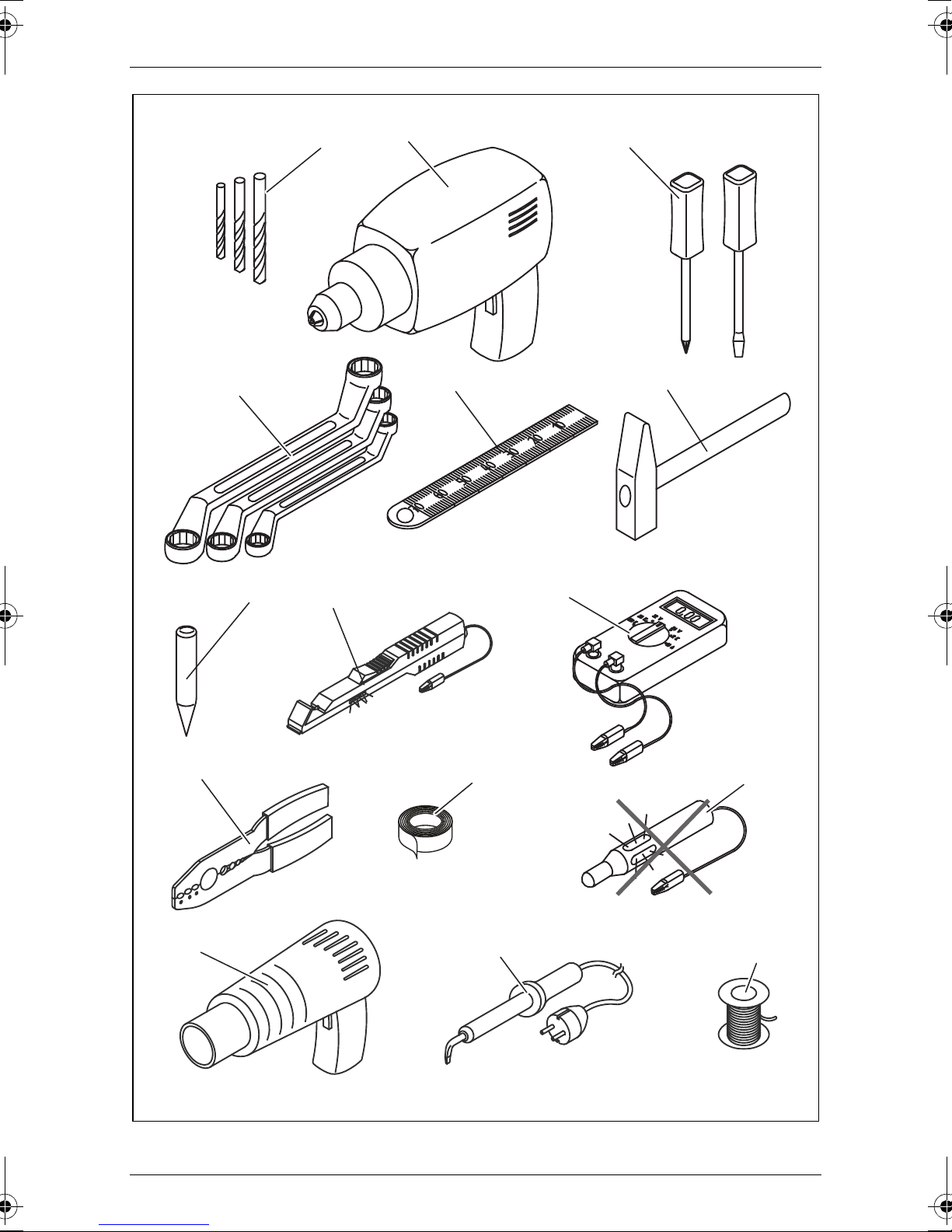
Benutzen Sie zum Prüfen der Spannung in elektrischen Leitungen nur eine
1
Diodenprüflampe (Abb.
8, Seite 2) oder ein Voltmeter (Abb.19,
Seite 2).
1
Prüflampen mit einem Leuchtkörper (Abb.
12, Seite 2) nehmen zu hohe
Ströme auf, wodurch die Fahrzeugelektronik beschädigt werden kann.
Beachten Sie beim Verlegen der elektrischen Anschlüsse (Abb. 3,
Seite 3), dass diese
– nicht geknickt oder verdreht werden,
– nicht an Kanten scheuern,
– nicht ohne Schutz durch scharfkantige Durchführungen verlegt
werden.
Isolieren Sie alle Verbindungen und Anschlüsse.
9

Lieferumfang MagicComfort MSH200
Sichern Sie die Kabel gegen mechanische Beanspruchung durch Kabel-
binder oder Isolierband, z. B. an vorhandenen Leitungen.
Beachten Sie folgende Hinweise bei der Verwendung der Sitzheizung:
Legen Sie keine spitzen oder schweren Gegenstände auf den Sitz, da
sonst die Sitzheizung beschädigt werden kann.
Personen mit gestörtem Wärmeempfinden sollten die Sitzheizung nur in
Stufe I betreiben.
Legen Sie bei eingeschalteter Sitzheizung keine wärmedämmenden
Gegenstände wie Decken oder Mäntel auf den Sitz.
Die Sitzheizung kann durch verschüttete Flüssigkeiten auf dem Sitz
beschädigt werden.
Schalten Sie die Sitzheizung niemals im nassen Zustand ein.
3Lieferumfang
Nr. in Abb. 4,
Seite 3
1 2 Heizelement Sitzfläche 9101700011
2 2 Heizelement Lehne 9101700012
3 2 Schalter-Anschlusskabel
4 2 Schalter 9101700021
5 1 Anschlusskabel Heizelement –
6 1 Schaltbox 9101700018
– 1 Bohrschablone
– 12 Doppelseitiges Klebeband
– 12 Isoliermaterial
– 1 Bedienungsanleitung
Menge Bezeichnung Artikel-Nr.
Schaltbox
10

MagicComfort MSH200 Bestimmungsgemäßer Gebrauch
4 Bestimmungsgemäßer Gebrauch
Die Sitzheizung MagicComfort MSH200 (Art.-Nr. 9101700020) ist geeignet
für den Einbau in die vorderen Fahrzeugsitze.
ACHTUNG!
Bei Fahrzeugen mit Seitenairbags in den Sitzlehnen, Sitz-
A
belegungserkennung oder Kindersitzerkennung sind die
Herstellerangaben des Fahrzeugherstellers zu beachten.
5 Technische Beschreibung
Die Heizelemente der Sitzheizung MagicComfort MSH200 können in den
Fahrersitz und den Beifahrersitz eingebaut werden.
Die Form des Sitzes wird durch die Heizelemente nicht verändert.
Die Bedienung der Sitzheizung erfolgt über einen Schalter.
6 Sitzheizung montieren
6.1 Benötigtes Werkzeug (Abb. 1, Seite 2)
Für Einbau und Montage benötigen Sie folgende Werkzeuge:
Satz Bohrer (1)
Bohrmaschine (2)
Schraubendreher (3)
Satz Ring- oder Maulschlüssel (4)
Maßstab (5)
Hammer (6)
Körner (7)
11

Sitzheizung montieren MagicComfort MSH200
Für den elektrischen Anschluss und seine Überprüfung benötigen Sie
folgende Hilfsmittel:
Diodenprüflampe (8) oder Voltmeter (9)
Krimpzange (10)
Isolierband (11)
Heißluftföhn (13)
Lötkolben (14)
Lötzinn (15)
Ggf. Kabeldurchführungstüllen
Zur Befestigung der Kabel benötigen Sie ggf. noch weitere Kabelbinder.
6.2 Sitzheizung montieren
Sitz demontieren
➤ Sichern Sie das Fahrzeug gegen Wegrollen.
ACHTUNG!
Beachten Sie bei Fahrzeugen mit Seitenairbags in der Sitzlehne
A
➤ Prüfen Sie die Einbaubarkeit anhand dieser Einbauanleitung und der
Herstellerinformation.
➤ Entfernen Sie die Befestigungsschrauben des Fahrzeugsitzes.
➤ Heben Sie den Sitz aus dem Fahrzeug.
Sitz vorbereiten
➤ Entfernen Sie alle Kunststoffverkleidungen des Sitzes, um die Befesti-
gungen des Bezugstoffes erreichen zu können.
➤ Trennen Sie die Lehne von der Sitzfläche (Abb. 7, Seite 4 und Abb. 8,
Seite 4).
➤ Öffnen Sie den Sitzbezug der Sitzfläche.
Der Bezugsstoff ist meist mit einer breiten Pappe oder einem Metalldraht
in einem Falz am Untergestell eingeklemmt.
die Herstellerangaben zur Demontage der Sitze und Polster.
➤ Lösen Sie die Befestigungen mit einem Schraubendreher und einer
Zange (Abb. 9, Seite 4 und Abb. 0, Seite 4).
➤ Lösen Sie eventuell vorhandene Polsterklammern oder Querstreben
(Abb. a, Seite 4).
➤ Öffnen Sie genauso auch den Bezug der Lehne.
12

MagicComfort MSH200 Sitzheizung montieren
Heizelemente vorbereiten
ACHTUNG!
Zur Vermeidung eines Kurzschlusses müssen Sie sämtliche
A
Schnittkanten mit dem mitgelieferten Isoliermaterial isolieren.
HINWEIS
I
➤ Legen Sie die Heizelemente auf die Sitzfläche und an die Lehne.
➤ Zeichnen Sie bei Abspanngräben in der Sitzfläche oder an der Lehne
diese Bereiche auf den Heizelementen an.
➤ Zeichnen Sie die benötigte Länge an. Berücksichtigen Sie dabei die Tiefe
von Abspanngräben, falls vorhanden. Das Heizelement wird nachher in
diese Abspanngräben eingelegt.
Sie können die Heizelemente auf die benötigte Länge
zuschneiden und dabei die beiden längs verlaufenden Leiterbahnen kürzen.
Im Bereich von Abspanngräben auf der Sitzfläche oder an der
Lehne können Sie einen Ausschnitt aus dem Heizelement
schneiden. Dabei dürfen Sie die Ausschnitte nur innerhalb der
beiden Leiterbahnen anfertigen (Abb. 5, Seite 3).
Schneiden Sie die Matte nicht längsseitig ein, da sie sonst im
Bereich des Einschnittes nicht geheizt wird (Abb. 5, Seite 3).
Die Heizfläche an der Lehne braucht nur ca. 30 – 35 cm über
die Sitzfläche zu reichen, da sich der Fahrer bei einer normalen
Sitzposition nur in diesem Bereich anlehnt (Abb. 6, Seite 3).
➤ Schneiden Sie das Heizelement auf die gewünschte Länge zu.
➤ Fertigen Sie bei Bedarf die Ausschnitte an.
➤ Isolieren Sie sämtliche Schnittkanten mit dem mitgelieferten Isolier-
material.
13

Sitzheizung montieren MagicComfort MSH200
Heizelement für die Sitzfläche montieren
➤ Führen Sie das Heizelement für die Sitzfläche zwischen Bezugsstoff und
Schaumkern der Sitzfläche ein (Abb. b, Seite 4).
➤ Falls Abspanngräben vorhanden sind: Sorgen Sie dafür, das die Aus-
schnitte über den Abspanngräben positioniert sind (Abb. c, Seite 4) und
legen Sie das Heizelement in die Abspanngräben ein.
➤ Fixieren Sie das Heizelement mit doppelseitigem Klebeband gegen Ver-
rutschen auf dem Schaumstoffkern.
Achten Sie darauf, dass sich keine Falten oder Knicke bilden.
Heizelement für die Lehne montieren
ACHTUNG!
Sind die Sitze mit Seitenairbags ausgestattet, so ist der Bezugs-
A
stoff mit Sollbruchstellen versehen. Der Sitzbezug darf daher nicht
zu stark gezogen oder verschoben werden.
➤ Öffnen Sie den Bezug der Lehne im unteren Bereich (Abb. d, Seite 4).
➤ Schieben Sie das Heizelement in den Zwischenraum zwischen Sitzbezug
und Sitzpolster ein (Abb. e, Seite 4).
➤ Fixieren Sie das Heizelement mit doppelseitigem Klebeband faltenfrei.
Sitz montieren
➤ Bauen Sie Lehne und Sitzfläche wieder zusammen.
➤ Heben Sie den Sitz ins Fahrzeug.
➤ Befestigen Sie den Fahrzeugsitz mit den Befestigungsschrauben.
Elektrisch anschließen
Den Gesamtschaltplan finden Sie in Abb. h, Seite 5.
ACHTUNG!
Achten Sie besonders im Bereich der Sitzschienen auf eine sichere
A
➤ Befestigen Sie die Schaltbox an einer geeigneten Stelle im Bereich des
Armaturenbretts (Abb. i, Seite 6).
Verlegung.
➤ Suchen Sie einen geeigneten Einbauort für den Sitzheizungsschalter.
Wenn möglich, benutzen Sie hierfür vorhandene Blindkappen.
Stellen Sie sicher, dass hinter der Verkleidung genügend Platz für die
Montage des Schalters vorhanden ist.
14

MagicComfort MSH200 Sitzheizung benutzen
➤ Zeichnen Sie den Schalterausschnitt mit der beiliegenden Schablone an
(Abb. j, Seite 6).
➤ Sparen Sie den markierten Bereich mit entsprechendem Werkzeug aus
➤ Montieren Sie den Schalter in die Aussparung (Abb. f, Seite 4).
➤ Verlegen Sie den vorgefertigten Kabelbaum, ohne dass die Kabel ein-
knicken bzw. durchscheuern können (Abb. g, Seite 4).
7 Sitzheizung benutzen
HINWEIS
Das Sitzheizungslogo (Abb. k 1, Seite 6) leuchtet auch, wenn die
I
➤ Stellen Sie die Sitzheizung mit dem Drehrad des zugehörigen Schalters
stufenlos von 0 bis H (hohe Heizwirkung) ein.
Sitzheizung ausgeschaltet ist.
✓ Die LED (Abb. k 2, Seite 6) am Schalter leuchtet grün.
➤ Zum Ausschalten der Sitzheizung: Stellen Sie den zugehörigen Schalter
auf Position 0.
✓ Die LED (Abb. k 2, Seite 6) am Schalter erlischt.
8 Gewährleistung
Es gilt die gesetzliche Gewährleistungsfrist. Sollte das Produkt defekt sein,
wenden Sie sich bitte an die Niederlassung des Herstellers in Ihrem Land
(Adressen siehe Rückseite der Anleitung) oder an Ihren Fachhändler.
Zur Reparatur- bzw. Gewährleistungsbearbeitung müssen Sie folgende
Unterlagen mitschicken:
eine Kopie der Rechnung mit Kaufdatum,
einen Reklamationsgrund oder eine Fehlerbeschreibung.
9 Entsorgung
➤ Geben Sie das Verpackungsmaterial möglichst in den entsprechenden
Recycling-Müll.
Wenn Sie das Produkt endgültig außer Betrieb nehmen, informieren Sie sich bitte beim nächsten Recyclingcenter oder bei
M
Ihrem Fachhändler über die zutreffenden Entsorgungsvorschriften.
15

Technische Daten MagicComfort MSH200
10 Technische Daten
MagicComfort MSH200
Art.-Nr. 9101700020
Betriebsspannung: 12 Vg
Leistung: Je Sitz stufenlos regelbar von
30–80Watt
Max. Stromaufnahme: 12 A
Abmessungen: Sitzelement: 600 x 280 mm
Lehnenelement: 600 x 280 mm
Ausführungen, dem technischen Fortschritt dienende Änderungen und
Liefermöglichkeiten vorbehalten.
16

MagicComfort MSH200 Notes on using the manual
Please read this operating manual carefully before starting the device.
Keep it in a safe place for future reference. If the device is handed over
to another person, this operating manual must be handed over along
with the device.
Contents
1 Notes on using the manual . . . . . . . . . . . . . . . . . . . . . . . . . . . . . . . 17
2 Safety and installation instructions. . . . . . . . . . . . . . . . . . . . . . . . . . 18
3 Scope of delivery . . . . . . . . . . . . . . . . . . . . . . . . . . . . . . . . . . . . . . . 20
4 Intended use . . . . . . . . . . . . . . . . . . . . . . . . . . . . . . . . . . . . . . . . . . 20
5 Technical description . . . . . . . . . . . . . . . . . . . . . . . . . . . . . . . . . . . . 21
6 Installing the seat heater . . . . . . . . . . . . . . . . . . . . . . . . . . . . . . . . . 21
7 Using the seat heater . . . . . . . . . . . . . . . . . . . . . . . . . . . . . . . . . . . . 25
8 Guarantee . . . . . . . . . . . . . . . . . . . . . . . . . . . . . . . . . . . . . . . . . . . . 25
9 Disposal . . . . . . . . . . . . . . . . . . . . . . . . . . . . . . . . . . . . . . . . . . . . . . 25
10 Technical data . . . . . . . . . . . . . . . . . . . . . . . . . . . . . . . . . . . . . . . . . 26
1 Notes on using the manual
WARNING!
Safety instruction: Failure to observe this instruction can cause
!
A
fatal or serious injury.
NOTICE!
Failure to observe this instruction can cause material damage and
impair the function of the product.
NOTE
Supplementary information for operating the product.
I
➤ Action: This symbol indicates that action is required on your part. The
required action is described step-by-step.
✓ This symbol describes the result of an action.
fig. 1 5, page 3: This refers to an element in an illustration. In this case,
item 5 in figure 1 on page 3.
17

Safety and installation instructions MagicComfort MSH200
2 Safety and installation instructions
Please observe the prescribed safety instructions and stipulations
from the vehicle manufacturer and service workshops.
The manufacturer accepts no liability for damage in the following cases:
Faulty assembly or connection
Damage to the product resulting from mechanical influences and excess
voltage
Alterations to the product without express permission from the manu-
facturer
Use for purposes other than those described in the operating manual
NOTICE!
To prevent the risk of short circuits, always disconnect the negative
A
terminal of the vehicle's electrical system before working on it.
If the vehicle has an additional battery, its negative terminal should
also be disconnected.
WARNING!
Inadequate supply cable connections could result in short circuits,
!
Please observe the following instructions:
When working on the following cables, only use insulated cable lugs,
plugs and flat push-on receptacles:
– 30 (direct supply from positive battery terminal)
– 15 (connected positive terminal, behind the battery)
– 31 (return cable from the battery, earth)
Do not use terminal strips.
The safest type of connection is to solder the ends of the cables together
and then insulate them.
which could have as a consequence that:
– Cable fires occur
– The airbag is triggered
– Electronic control devices are damaged
– Electric functions fail (indicators, brake light, horn, ignition,
lights)
Only use insulated cable terminals, plugs and flat sockets for releasable
connections. Do not use crimp terminals (cable connectors) or terminal
strips.
Use a crimping tool (fig. 1 10, page 2) to connect the cables.
18

MagicComfort MSH200 Safety and installation instructions
When connecting to cable 31 (earth), screw the cable
– To the vehicle's earth bolt with a cable lug and a gear disc or
– To the sheet-metal bodywork with a cable lug and a self-tapping
screw.
Ensure that there is a good earth connection.
If you disconnect the negative terminal of the battery, all data stored in the
volatile memories will be lost.
The following data must be set again, depending on the vehicle equip-
ment options:
– Radio code
– Vehicle clock
–Timer
– On-board computer
– Seat position
You can find instructions for making these settings in the appropriate
operating instructions.
Observe the following installation instructions:
Secure the parts installed in the vehicle in such a way that they cannot
become loose under any circumstances (sudden braking, accidents) and
cause injuries to the occupants of the vehicle.
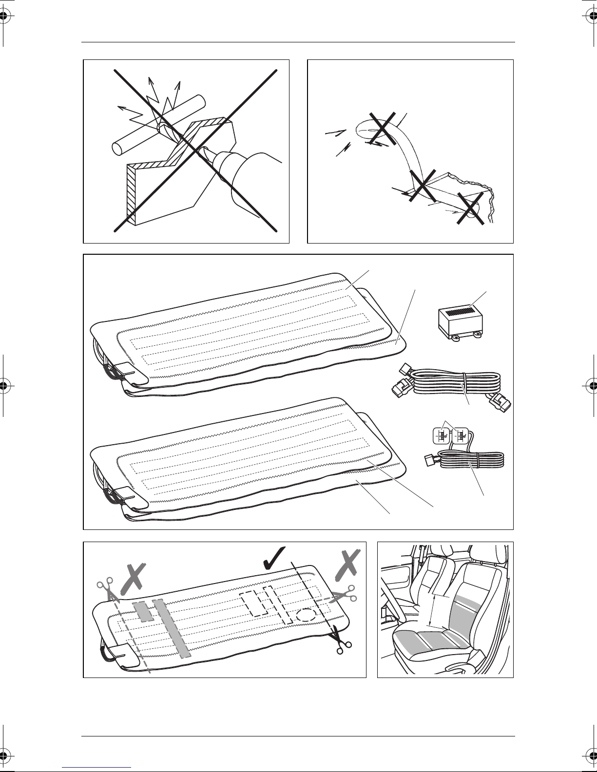
To prevent damage, when drilling ensure that there is sufficient space on
the other side for the drill head to come out (fig. 2, page 3).
Deburr all drill holes and treat them with a rust-protection agent.
Observe the following instructions when working with electrical parts:
When testing the voltage in electrical cables, only use a diode test lamp
(fig. 1 8, page 2) or a voltmeter (fig. 1 9, page 2).
Test lamps with an illuminant (fig. 1 12, page 2) take up voltages which
are too high and which can damage the vehicle's electronic system.
When making electrical connections (fig. 3, page 3), ensure that
– They are not kinked or twisted
– They do not rub on edges
– They are not laid in sharp-edged ducts without protection.
Insulate all connections.
Secure the cables against mechanical wear with cable binders or insulat-
ing tape, for example to existing cables.
19

Scope of delivery MagicComfort MSH200
Observe the following instructions when using the seat heater:
Do not place any sharp or heavy objects on the seat, as the seat heater
could otherwise be damaged.
Persons with an impaired sensitivity to heat should only operate the seat
heater at level I.
Do not place any heat insulating objects, such as blankets or coats, on the
seat when the seat heater is switched on.
The seat heater can be damaged by fluids spilt on the seat.
Never switch the seat heater on when it is wet.
3 Scope of delivery
No. in fig. 4,
page 3
1 2 Seat surface heating element 9101700011
2 2 Backrest heating element 9101700012
3 2 Switch connection cable
4 2 Switch 9101700021
5 1 Heating element connection
6 1 Switchbox 9101700018
– 1 Drill template
– 12 Double-sided adhesive tape
– 12 Insulating material
– 1 Operating manual
Quantity Designation Item no.
cable – switchbox
4 Intended use
The MagicComfort MSH200 (item no. 9101700020) seat heater is suitable
for fitting in the front vehicle seats.
NOTICE!
For vehicles equipped with side airbags in the seat backrests, seat
A
20
occupancy detection or child seat detection, observe the vehicle
manufacturer's specifications.

MagicComfort MSH200 Technical description
5 Technical description
The heating elements for the MagicComfort MSH200 seat heater can be
installed in the driver's seat and the passenger seat.
The shape of the seat is not altered by the heating elements.
The seat heater is operated using a switch.
6 Installing the seat heater
6.1 Tools required (fig. 1, page 2)
For installation and assembly you will need the following tools:
Drill bit set (1)
Drill (2)
Screwdriver (3)
Set of ring or open-ended spanners (4)
Measuring ruler (5)
Hammer (6)
Centre punch (7)
To make and test the electrical connection, the following tools are required:
Diode test lamp (8) or voltmeter (9)
Crimping tool (10)
Insulating tape (11)
Hot air blower (13)
Soldering iron (14)
Solder (15)
Cable bushing sleeves (if necessary)
To fasten the cables you may require additional cable binders.
21

Installing the seat heater MagicComfort MSH200
6.2 Installing the seat heater
Removing the seat
➤ Secure the vehicle against rolling away.
NOTICE!
For vehicles with side air bags in the seat backrest, observe the
A
➤ Check the suitability for installation using these installation instructions
and the manufacturer's information.
➤ Remove the fastening screws from the vehicle seat.
➤ Lift the seat out of the vehicle.
Preparing the seat
manufacturer's instructions on removing the seats and the upholstery.
➤ Remove all plastic panelling from the seat to ensure the fastening of the
cover fabric can be reached.
➤ Separate the backrest from the seat (fig. 7, page 4 and fig. 8, page 4).
➤ Open the seat cover on the seat surface.
The cover fabric is usually tucked into a seam on the frame with a wide
cardboard strip or metal wire.
➤ Remove the fasteners using a screwdriver and pliers (fig. 9, page 4 and
fig. 0, page 4).
➤ Remove any upholstery staples or cross braces (fig. a, page 4).
➤ Open the cover of the backrest in the same way.
22

MagicComfort MSH200 Installing the seat heater
Preparing the heating elements
NOTICE!
Insulate all the trimmed ends with the insulating material supplied
A
to prevent a short circuit.
NOTE
I
➤ Place the heating elements on the seat and backrest.
➤ If there are anchoring grooves in the seat or the backrest, mark these
areas on the heating elements.
➤ Mark the required lengths. Take into account the depth of the anchoring
grooves, if present. The heating element is inserted in these anchoring
grooves.
You can cut the heating elements to the required length and
shorten the lengths of the two conductor paths.
You can cut out a section of the heating element in the area of
the anchoring grooves on the seat or the backrest. Make sure
the cut-out sections are only made between the two conductor
paths (fig. 5, page 3).
Do not cut the mat lengthways, otherwise it will not be heated in
the area of the incision (fig. 5, page 3).
The heating surface on the backrest only needs to extend
approx. 30 – 35 cm above the seat, as the driver only leans
against this area when sitting normally (fig. 6, page 3).
➤ Trim the heating element to the required length.
➤ Customise the cut-out sections as required.
➤ Insulate all the trimmed ends with the insulating material.
Installing the heating element for the seat surface
➤ Insert the heating element for the seat surface between the cover fabric
and the foam core of the seat (fig. b, page 4).
➤ If anchoring grooves are present, make sure that the cut-out sections are
positioned over the anchoring grooves (fig. c, page 4) and place the
heating elements in the anchoring grooves.
➤ Fasten the heating element using double-sided adhesive tape to prevent
it sliding on the foam core.
Ensure that no creases or kinks form.
23
Installing the seat heater MagicComfort MSH200
Installing the heating element for the backrest
NOTICE!
If the seats are equipped with side airbags, then there is a prede-
A
➤ Open the lower area of the backrest cover (fig. d, page 4).
➤ Push the heating element into the gap between the seat cover and the
seat cushion (fig. e, page 4).
➤ Fasten the heating element using double-sided adhesive tape to prevent
creases.
Installing the seat
➤ Reassemble the backrest and seat.
➤ Lift the seat into the vehicle.
termined breaking point in the cover fabric. The seat cover must
therefore not be pulled tightly or slip out of place.
➤ Secure the vehicle seat with the fastening screws.
Electrical connection
The complete circuit diagram can be found in fig. h, page 5.
NOTICE!
Ensure it has been securely fitted, particularly in the area of the
A
➤ Attach the switchbox to a suitable location in the vicinity of the dashboard
(fig. i, page 6).
➤ Find a suitable place for installing the seat heater switch.
If possible, use the blanking plugs provided for this purpose.
Ensure that there is enough room behind the panel for the installation of
the switch.
➤ Mark the switch cut-out using the template provided (fig. j, page 6).
➤ Cut out the marked area with an appropriate tool.
seat rails.
➤ Install the switch into the cut-out (fig. f, page 4).
➤ Install the ready-made wiring harness so that the cables cannot bend or
fray (fig. g, page 4).
24

MagicComfort MSH200 Using the seat heater
7 Using the seat heater
NOTE
The seat heating logo (fig. k 1, page 6) also lights up when the
I
➤ Adjust the seat heating from 0 to H (high output) using the rotary wheel of
the accompanying switch.
✓ The LED (fig. k 2, page 6) on the switch lights up green.
➤ To switch the seat heater off: Turn the corresponding switch to position 0.
✓ The LED (fig. k 2, page 6) on the switch goes out.
seat heating is switched on.
8 Guarantee
The statutory warranty period applies. If the product is defective, please
contact the manufacturer's branch in your country (see the back of the
instruction manual for the addresses) or your retailer.
For repair and guarantee processing, please include the following documents when you send in the device:
A copy of the receipt with purchasing date
A reason for the claim or description of the fault
9 Disposal
➤ Place the packaging material in the appropriate recycling waste bins
wherever possible.
If you wish to finally dispose of the product, ask your local recycling
centre or specialist dealer for details about how to do this in
M
accordance with the applicable disposal regulations.
25

Technical data MagicComfort MSH200
10 Technical data
MagicComfort MSH200
Item no. 9101700020
Operating voltage: 12 Vg
Power: Each seat can be continuously adjusted from
30–80 watts.
Max. power consumption: 12 A
Dimensions: Seat element: 600 x 280 mm
Backrest element: 600 x 280 mm
Versions, technical improvements and delivery options reserved.
26

MagicComfort MSH200 Remarques concernant l’application des instructions
Veuillez lire ce manuel avec attention avant la mise en service puis
conservez-le. En cas de revente de l’appareil, veuillez le transmettre au
nouvel acquéreur.
Table des matières
1 Remarques concernant l’application des instructions . . . . . . . . . . . 27
2 Consignes de sécurité et instructions de montage . . . . . . . . . . . . . 28
3 Contenu de la livraison . . . . . . . . . . . . . . . . . . . . . . . . . . . . . . . . . . 31
4 Usage conforme. . . . . . . . . . . . . . . . . . . . . . . . . . . . . . . . . . . . . . . . 31
5 Description technique . . . . . . . . . . . . . . . . . . . . . . . . . . . . . . . . . . . 31
6 Montage du chauffage de siège. . . . . . . . . . . . . . . . . . . . . . . . . . . . 32
7 Utilisation du chauffage de siège . . . . . . . . . . . . . . . . . . . . . . . . . . . 35
8 Garantie . . . . . . . . . . . . . . . . . . . . . . . . . . . . . . . . . . . . . . . . . . . . . . 36
9 Retraitement . . . . . . . . . . . . . . . . . . . . . . . . . . . . . . . . . . . . . . . . . . 36
10 Caractéristiques techniques. . . . . . . . . . . . . . . . . . . . . . . . . . . . . . . 36
1 Remarques concernant l’application
des instructions
AVERTISSEMENT !
Consigne de sécurité : le non-respect de ces consignes peut
!
A
entraîner la mort ou de graves blessures.
AVIS !
Le non-respect de ces consignes peut entraîner des dommages
matériels et des dysfonctionnements du produit.
REMARQUE
Informations complémentaires sur l'utilisation du produit.
I
➤ Manipulation : ce symbole vous indique une action à effectuer. Les
manipulations à effectuer sont décrites étape par étape.
✓ Ce symbole décrit le résultat d’une manipulation.
fig. 1 5, page 3 : cette information renvoie à un élément figurant sur une
illustration, dans cet exemple à la « position 5 de l'illustration 1 à la page 3 ».
27

Consignes de sécurité et instructions de montage MagicComfort MSH200
2 Consignes de sécurité et instructions
de montage
Respectez les consignes de sécurité et autres prescriptions imposées
par le fabricant du véhicule et par les professionnels de l'automobile !
Le fabricant décline toute responsabilité pour des dommages dans les cas
suivants :
des défauts de montage ou de raccordement
des influences mécaniques et des surtensions ayant endommagé le
matériel
des modifications apportées au produit sans autorisation explicite de la
part du fabricant
une utilisation différente de celle décrite dans la notice
AVIS !
Débranchez toujours la borne négative avant de procéder à des
A
travaux sur les éléments électriques du véhicule afin d’éviter tout
risque de court-circuit.
Sur les véhicules équipés d’une batterie supplémentaire, vous
devez également débrancher le pôle négatif de cette dernière.
!
AVERTISSEMENT !
Tout branchement électrique inadéquat peut entraîner un courtcircuit causant
– la combustion de câbles,
– le déclenchement de l'airbag,
– l’endommagement des dispositifs électroniques de commande,
– la défaillance des fonctions électriques (clignotants, feux-stop,
klaxon, allumage, éclairage).
28

MagicComfort MSH200 Consignes de sécurité et instructions de montage
Veillez donc à respecter les consignes suivantes :
Pour tous travaux sur les lignes électriques suivantes, n’utilisez que des
cosses de câble, fiches et alvéoles pour contacts plats isolés :
– 30 (entrée directe pôle positif de la batterie),
– 15 (pôle positif connecté, derrière la batterie),
– 31 (circuit de retour à partir de la batterie, masse).
N’utilisez pas de dominos.
La méthode la plus sûre pour effectuer la liaison est d'assembler les ex-
trémités de câbles par soudure, puis de les isoler.
Dans le cas de connexions démontables, utilisez uniquement des cos-
ses de câble, des fiches et des contacts plats isolés. N'utilisez jamais de
connecteurs sertis (connecteurs de câbles), ni de barrettes de connexion.
Utilisez une pince à sertir (fig. 1 10, page 2) pour relier les câbles.
Pour les raccordements à la ligne électrique 31 (masse), vissez le câble
– à une vis de masse du véhicule, avec une cosse de câble et une
rondelle crantée, ou bien
– à la carrosserie, avec une cosse de câble et une vis à tôle.
Assurez-vous du bon déroulement du transfert de masse !
Lorsque vous débranchez le pôle négatif de la batterie, les mémoires
volatiles de l’électronique de confort perdent toutes les données
enregistrées.
Vous devez procéder à un nouveau réglage des données suivantes en
fonction de l’équipement du véhicule :
– code radio
– horloge du véhicule
– minuterie
– ordinateur de bord
– position du siège
Les instructions de réglage sont énoncées dans les notices d’utilisation
correspondantes.
29

Consignes de sécurité et instructions de montage MagicComfort MSH200
Veillez à respecter les consignes suivantes lors du montage :
Fixez les pièces installées dans le véhicule de manière à ce qu’elles ne
puissent en aucun cas se desserrer (freinage abrupt, accident) et risquer
de causer des blessures aux occupants du véhicule.
Avant de percer des trous, assurez-vous que vous disposez d’un espace
suffisant de l'autre côté du trou à percer afin que la mèche n'occasionne
aucun dégât (fig. 2, page 3).
Ebavurez tous les trous et protégez-les avec un enduit anticorrosif.
Veillez à respecter les consignes suivantes lors de travaux sur des éléments
électriques :
Pour le contrôle de la tension des lignes électriques, n’utilisez qu’une lam-
pe étalon à diode (fig. 1 8, page 2) ou un voltmètre (fig. 1 9, page 2).
Les lampes étalon (fig. 1 12, page 2) à corps lumineux absorbent des
courants trop élevés qui pourraient endommager les composants électroniques du véhicule.
Lors de l'installation des raccordements électriques (fig. 3, page 3),
veillez à ce que ceux-ci
– ne soient ni pliés, ni tordus,
– ne frottent pas contre des arêtes,
– ne soient pas placés dans des passages à arêtes vives sans
protection.
Isolez toutes les connexions et tous les raccords.
Protégez les câbles contre toute contrainte mécanique en les fixant par
exemple aux lignes existantes à l'aide de serre-câbles ou de ruban vinyl.
Veillez à respecter les consignes suivantes lors de l'utilisation du chauffage
de siège :
Ne posez pas d'objets pointus ou lourds sur le siège afin de ne pas en-
dommager le chauffage de siège.
Pour les personnes ayant des problèmes de sensibilité à la chaleur, il est
recommandé d'utiliser le chauffage de siège uniquement au niveau I.
Il est interdit de poser des objets empêchant le passage de la chaleur tels
que des couvertures ou des manteaux sur le siège tant que le chauffage
de siège est en marche.
Le chauffage de siège risque d'être endommagé si des liquides sont ren-
versés sur le siège.
Le chauffage de siège ne doit pas être mis en marche s'il est humide.
30
 Loading...