

V-ZUG CookTopInduction V4000 CTI4T64 Series, CookTopInduction V4000 CTI4T74 Series, CookTopInduction V4000 CTI4T64MMSLD, CookTopInduction V4000 CTI4T64MMSOLD, CookTopInduction V4000 CTI4T64MMSLU Installation Instructions Manual
...Page 1

Installation instructions
1065985-R01
Connection plate
Identification plate
CTI4T64/74
CookTopInduction V4000
Glass ceramic hob
The appliance should be installed by qualified personnel only. Each step must be carried out and checked in full in
the order specified.
1065985-R01
23/04/2019
Validity
These installation instructions apply to the following models:
Model number With normal mounting frame With DualDesign With oversize mounting frame
31115 CTI4T64MMSLC, CTI4T64MMSOLC CTI4T64MMSLD,
CTI4T64MMSOLD
31116 CTI4T74MMSLC, CTI4T74MMSOLC CTI4T74MMSLD,
CTI4T74MMSOLD
CTI4T64MMSLU, CTI4T64MMSOLU
-
General notes
If installing into a combustible material, the guidelines and standards for low-voltage installations and fire protection
must be strictly observed.
Identification plate
The identification plate is located next to the connection plate.
▸ Affix the second identification plate (supplied) in an accessible position behind the front of the fitted cabinet beneath the appliance.
1
Page 2
Installation instructions
1065985-R01
CTI4T64/74
CookTopInduction V4000
Glass ceramic hob
1065985-R01
23/04/2019
Installation accessories supplied
Oversize mounting frame:
Designation Art. no.
Adjusting brace set H61548
Flush installation:
Designation Art. no.
Cementing-in instructions J004133
Sealing strip set H63283
Spacer set H60330
Accessories
For all installation variants:
Designation Art. no.
Ventilation protective plate set for niche width 550mm H61082
Ventilation protective plate set for niche width 600mm H61083
Ventilation protective plate set for niche width 825mm H61084
Ventilation protective plate set for niche width 900mm H61085
Surface-mounted installation:
Designation Art. no.
Stainless steel intermediate support for the surface-mounted combination of several hobs 1014361
Black intermediate support for the surface-mounted combination of several hobs 1019199
Flush installation:
Designation Art. no.
Steel angle set, installation dimension 60 H63772
Steel angle set, installation dimension 70 H63773
Steel angle set, installation dimension 80 H63774
Instant adhesive for installation of the steel angle (50ml) B11657
Straight mixing nozzle B11656
TREMCLEAN isopropyl alcohol (1000ml) 1056609
Black silicone FA880 (310ml) B11555
Anthracite silicone FA880 (310ml) B11556
White silicone FA880 (310ml) 1031313
Stone grey silicone FA880 (310ml) 1031314
Marble smoothing agent AA320 (1000ml) B11557
Fugenboy (silicone finishing tool) B75158
2
Page 3
Installation instructions
1065985-R01
Installation pipe Distribution boxClamp
brown + black
blue
yellow/green
black
blue
yellow/green
brown
L2
L1
N
N
L1
PE/
PE/
400 V 2N~
230 V~
≥15
21
CTI4T64/74
CookTopInduction V4000
Glass ceramic hob
1065985-R01
23/04/2019
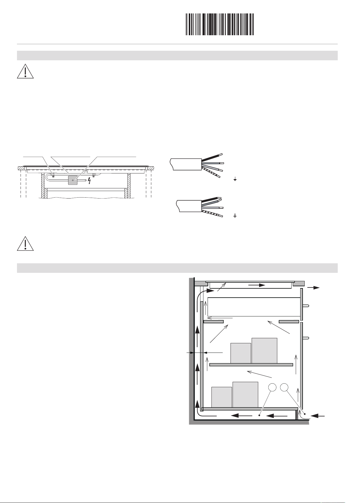
Electrical connection
Electrical connections must be carried out by qualified personnel in accordance with the guidelines and standards
for low-voltage installations and the specifications of the local electricity supply companies.
Refer to the identification plate for information on the required mains voltage, current type and fuse protection.
A plug-in appliance may only be connected to a socket outlet with earthing contact, installed according to specifications. An
all-pole mains isolating device with 3 mm contact opening should be provided in the house wiring system. Switches, plug and
socket devices, circuit breakers and fusible cut-outs which are accessible after installation and which have all-poles switching
are permissible as isolating devices. Effective earthing and separately installed neutral and earth conductors ensure safe and
fault-free operation. After installation, live parts and cables with basic insulation must not be accessible. Check old installations.
▸ If the hobs are used at an altitude of over 2,000 meters above sea level, a reduced performance must be expected.
The appliance is equipped with a connection cable which must be connected to an on-site junction box.
Error message U400
Faulty connection:
A pole conductor has been connected to the connection terminal for neutral conductors.
Quickly disconnect the appliance from the mains!
Ventilation
In order to guarantee good ventilation, a space of ≥10mm
height is necessary beneath the appliance.
1. The rear panel of the base unit must be open around the
work surface cut-out to guarantee continuous air circulation via the ventilation slits.
The air must be drawn in from outside the cabinet and be
able to circulate freely from inside the cabinet to the hob.
2. Alternatively, a concealed fresh air supply can ensure air
circulation inside the cabinet.
In order that enough cold air can be drawn in, there must
be a continuous circulation of fresh air that extends outside
the cabinet.
The air must be drawn in from outside the cabinet and be
able to circulate freely from inside the cabinet to the hob.
3
Page 4

Installation instructions
1065985-R01
H
5
8
4
514
Y
Y
490±1
56
0±1
≥
50
≥
5
0
A
550/600
≥57**
Ri
Ra
≥10 *
B
Y – Y
H
Drawer/cabinet
514
H
704
Y
Y
Ri
490±1
≥50
≥50
A
680±1
55
0/
60
0
=
=
=
=
Ra
CTI4T74MMSLC,
CTI4T74MMSOLC
CTI4T64MMSLC,
CTI4T64MMSOLC
Cable length 1.7 mCable length 1.7 m
CTI4T64/74
CookTopInduction V4000
Glass ceramic hob
General information about installation
▪ The worktop must be flat so that it is sufficiently sealed against the ingress of liquids.
▪ In order to guarantee good ventilation, a space of at least 10mm in height is necessary beneath the appliance.
Overlying installation with normal mounting frame
The layout of the hob to be fitted may differ from the hob illustrated!
1065985-R01
23/04/2019
* The required clearance must be observed!
** Cut out if niche width 550mm
Type A Depends on producer B H Corner radius Ra/Ri
CTI4T64MMSLC, CTI4T64MMSOLC,
CTI4T74MMSLC, CTI4T74MMSOLC
A Worktop depth (in combination with directly built-under oven; does not apply to small appliances)
B Required clearance for ventilation and service replacement over the entire cut-out area.
H Dimension from the top of the work surface to the underside of the hob (ventilation opening)
Ri Corner radii of appliance Ra Outer corner radii of cut-out
≥20mm ≥60mm 50mm 10/8mm
Installation
1. Create the mounting cut-out accurately.
2. Carefully place the appliance in the mounting cut-out and push against the work surface until flat.
4
Page 5

Installation instructions
1065985-R01
490±1
≥50
≥50
A
680±1
55
0/
60
0
=
=
=
=
Ra
571
50
1
Y
Y
Ri
H
490±1
56
0±1
≥
50
≥
5
0
A
550/600
Ra
501
Ri
H
691
Y
Y
≥10 *
B
Y – Y
H
Drawer/cabinet
CTI4T74MMSLD,
CTI4T74MMSOLD
CTI4T64MMSLD,
CTI4T64MMSOLD
Cable length 1.7 mCable length 1.7 m
CTI4T64/74
CookTopInduction V4000
Glass ceramic hob
Overlying installation
The layout of the hob to be fitted may differ from the hob illustrated!
1065985-R01
23/04/2019
* The required clearance must be observed!
Type A Depends on producer B H Corner radius Ra/Ri
CTI4T64MMSLD, CTI4T64MMSOLD,
CTI4T74MMSLD, CTI4T74MMSOLD
A Worktop depth (in combination with directly built-under oven; does not apply to small appliances)
B Required clearance for ventilation and service replacement over the entire cut-out area.
H Dimension from the top of the work surface to the underside of the hob (ventilation opening)
Ri Corner radii of appliance Ra Outer corner radii of cut-out
≥20mm ≥60mm 50mm 5/1.5mm
Installation
1. Create the mounting cut-out accurately.
2. Carefully place the appliance in the mounting cut-out and push against the work surface until flat.
5
Page 6

Installation instructions
1065985-R01
507±
1
5
7
7±1
≥41.5
≥41.5
A
550/
600
571
50
1
Y
Y
X
X
Ri
Z
H
501
691
Y
Y
A
5
07±1
≥41.5
≥4
1
.
5
5
5
0
/600
Z
697
±1
X
X
Ri
H
CTI4T64MMSLD,
CTI4T64MMSOLD
CTI4T74MMSLD,
CTI4T74MMSOLD
Cable length 1.7 mCable length 1.7 m
H
≥10 *
Y – Y
B
Drawer/cabinet
Side panel
B
H
≥10 *
X – X
550/600
C
D
Ra
R0–5
8.5
0
-1
8.5
0
-0.5
8.5
8.5
+1
0
+1
0
Detail Z
Steel angle mounted
with adhesive or screws
CTI4T64/74
CookTopInduction V4000
Glass ceramic hob
Flush installation
The layout of the hob to be fitted may differ from the hob illustrated!
1065985-R01
23/04/2019
* The required clearance for ventilation must be observed!
Type A Depends on producer B C/D H Corner radius Ra/Ri
CTI4T64MMSLD, CTI4T64MMSOLD ≥20mm ≥75mm 560/490 51.7mm 5/1.5mm
CTI4T74MMSLD, CTI4T74MMSOLD 680/490
A Worktop depth (in combination with directly built-under oven; does not apply to small appliances)
B Required clearance for ventilation and service replacement over the entire cut-out area.
H Dimension from the top of the work surface to the underside of the hob (ventilation opening)
Ri Corner radii of appliance Ra Outer corner radii of cut-out
Installation
1. Create an accurate installation cut-out.
– The mounting surface can be reamed out or created by installing wood/stone supports or using the steel angle set (see Accessor-
ies).
Access to the appliance from below via the entire cut-out area must be guaranteed. For servicing purposes, the induction generator can be removed from below with the mounting plate. It must be possible to unscrew the contact-proof covers from below.
2. Prepare the cut-out and appliance in accordance with the specifications in the enclosed cementing-in instructions.
3. Carefully cement the appliance in and leave the silicone sealant to dry for at least 24 hours.
4. Connect to the electrical mains connection before inserting the appliance, if necessary.
6
Page 7

Installation instructions
1065985-R01
490–530
560–585
550/600
=
=
A
H
600
545
Ri
Ra
Y
Y
≥10 *
B
Y – Y
H
Drawer/cabinet
CTI4T64MMSLU, CTI4T64MMSOLU
Cable length 1.7 m
CTI4T64/74
CookTopInduction V4000
Glass ceramic hob
Installation with oversize mounting frame
The layout of the hob to be fitted may differ from the hob illustrated!
1065985-R01
23/04/2019
* The required clearance must be observed!
Type A Depends on producer B H Corner radius Ra/Ri
CTI4T64MMSLU, CTI4T64MMSOLU ≥20mm ≥58.2mm 48.2mm 10/8mm
A Worktop depth (in combination with directly built-under oven; does not apply to small appliances)
B Required clearance for ventilation and service replacement over the entire cut-out area.
H Dimension from the top of the work surface to the underside of the hob (ventilation opening)
Ri Corner radii of appliance Ra Outer corner radii of cut-out
The appliances with oversize frames can also be used as a replacement for solid plate hobs and for installation in complete chromenickel steel covers. In the latter case, the solid plate hob part is cut out of the chrome-nickel steel cover and replaced by an appliance
(depth of the work surface ≥30mm). In contrast to normal installation without a fastening system, the appliance is fixed from below using adjusting braces.
7
Page 8

Installation instructions
1065985-R01
560–585
490–530
=
=
(30)
6 adjusting braces
Aim for
≤R10
≤25
≤32
E D
40
30
(≤ screw length)
(≤ screw length)
Warning, glass breakage:
Do not overtighten screws
Reinforcing slats:
≥25 × 25 mm
Plate for chrome-nickel steel cover
CTI4T64/74
CookTopInduction V4000
Glass ceramic hob
Variable areas of the special cut-out dimensions
CTI4T64MMSLU, CTI4T64MMSOLU
1065985-R01
23/04/2019
Reinforcement of the cut-outs with
a complete chrome-nickel steel cover
The installation instructions with regard to electrical and safety-related issues remain fully valid for this installation.
1. Make a precise, right-angled cut-out in the work surface (if not already present). Aim to keep the cut-out dimensions to a minimum.
2. Securely clamp the appliance in the cut-out using the enclosed adjusting braces D and screws E. If necessary, install reinforcing
slats and use these to make the cover flat.
Arrangement of the adjusting braces
8
Page 9

Installation instructions
1065985-R01
393
(30)
≥67.5
5..10
53.5
56
ø4
≥15
(X)
H
≥3
≤
0.5
2.5
Caution: Mains cable must
not touch protective plate!
Well-fitting seal over
width of cabinet element
Air gap over entire width of
cabinet element
≥17 cm²
According to template
Drawer
Fan
≥5
≥15
(30)
550/600
825/900
H
B
Drawer Centre of fan
≥25 cm²
Air gap over the entire cabinet element width
A
CTI4T64/74
CookTopInduction V4000
Glass ceramic hob
Installation of the ventilation protective plate with 3 mm ventilation gap at the front
A protective plate is necessary for the adequate ventilation of the hob.
The distance between the underside of the appliance and the protective plate must be ≥10mm.
1065985-R01
23/04/2019
Type X Remarks
CTI4T64MMSLC, CTI4T64MMSOLC, CTI4T74MMSLC, CTI4T74MMSOLC 12mm Normal mounting frame
CTI4T64MMSLD, CTI4T64MMSOLD, CTI4T74MMSLD, CTI4T74MMSOLD 12mm Surface-mounted installation
CTI4T64MMSLD, CTI4T64MMSOLD, CTI4T74MMSLD, CTI4T74MMSOLD 10mm Flush installation
CTI4T64MMSLU, CTI4T64MMSOLU 13mm With oversize mounting frame
H Dimension from the top of the work surface to the underside of the hob (ventilation opening).
Cool air supply with regard to drawer or cabinet installed below
In order to guarantee good ventilation, a space of ≥ 10mm height is necessary beneath the appliance.
A Necessary space below the worktop for the appliance.
B Necessary space below the worktop for the ventilation of the appliance.
H Dimension from the top of the work surface to the underside of the hob (ventilation opening)
9
 Loading...