

Page 1
S JGFE
10
Page 2

Page 3

English ......................................................................................4
Français...................................................................................14
Deutsch ...................................................................................26
Español ...................................................................................36
日本語 .......................................................................................46
3
Page 4
IMPORTANT SAFETY INSTRUCTIONS
• Read these instructions.
• Keep these instructions.
• Heed all warnings.
• Follow all instructions.
• Do not use this apparatus near water.
• Mains powered apparatus shall not be exposed to dripping
or splashing and that no objects filled with liquids, such as
vases, shall be placed on the apparatus.
• Clean only with dry cloth.
• Do not block any ventilation openings. Install in
accordance with the manufacturer’s instructions.
• Do not install near any heat sources such as radiators,
heat registers, stoves, or other apparatus (including
amplifiers) that produce heat.
• Do not defeat the safety purpose of the polarized or
grounding-type plug. A polarized plug has two blades with
one wider than the other. A grounding type plug has two
blades and a third grounding prong. The wide blade or the
third prong are provided for your safety. If the provided
plug does not fit into your outlet, consult an electrician for
replacement of the obsolete outlet. (for USA and Canada)
• Protect the power cord from being walked on or pinched
particularly at plugs, convenience receptacles, and the
point where they exit from the apparatus.
• Only use attachments/accessories specified by the
manufacturer.
• Unplug this apparatus during lightning storms or when
unused for long periods of time.
• Turning off the power switch does not completely isolate
this product from the power line so remove the plug from
the socket if not using it for extended periods of time.
• Install this product near the wall socket and keep the
power plug easily accessible.
• WARNING—This apparatus shall be connected to a mains
socket outlet with a protective earthing connection.
• Refer all servicing to qualified service personnel. Servicing
is required when the apparatus has been damaged in any
way, such as power-supply cord or plug is damaged, liquid
has been spilled or objects have fallen into the apparatus,
the apparatus has been exposed to rain or moisture, does
not operate normally, or has been dropped.
• Do not install this equipment on the far position from wall
outlet and/or convenience receptacle.
• Do not install this equipment in a confined space such as a
box for the conveyance or similar unit.
• Excessive sound pressure from earphones and
headphones can cause hearing loss.
• Use only with the cart, stand, tripod, bracket, or table
specified by the manufacturer, or sold with the apparatus.
When a cart is used, use caution when moving the cart/
apparatus combination to avoid injury from tip-over.
manner will prevent harm to human health and potential damage to the environment. Since the correct method of disposal
will depend on the applicable laws and regulations in your
locality, please contact your local administrative body for
details. If the battery contains heavy metals in excess of the
regulated amount, a chemical symbol is displayed below the
“crossed-out wheeled bin” symbol on the battery or battery
package.
* All product names and company names are the trademarks
or registered trademarks of their respective owners.
The lightning flash with arrowhead symbol
within an equilateral triangle, is intended to
alert the user to the presence of uninsulated
“dangerous voltage” within the product’s
enclosure that may be of sufficient magnitude
to constitute a risk of electric shock to persons.
The exclamation point within an equilateral triangle is intended to alert the user to the presence of important operating and maintenance
(servicing) instructions in the literature accompanying the product.
Notice regarding disposal (EU only)
When this “crossed-out wheeled bin” symbol is displayed on the product, owner’s manual, battery, or
battery package, it signifies that when you wish to dispose of this product, manual, package or battery you
must do so in an approved manner. Do not discard
this product, manual, package or battery along with
ordinary household waste. Disposing in the correct
• This apparatus is for moderate climates areas use, not
suitable for use in tropical climates countries.
• The ventilation should not be impeded by covering the
ventilation openings with items, such as newspapers,
table-cloths, curtains, etc.
• No naked flame sources, such as lighted candles, should
be placed on the apparatus.
4
Page 5

INTRODUCTION
Congratulations on your purchase of the VOX Custom Series Guitar Amplifier AC30C2X/AC30C2/
AC30C2-TV/AC15C1X/AC15C2/AC15C1/AC15C1-TV / VOX Custom Series Guitar Amplifier Head
AC30CH/AC15CH / Speaker cabinet V212C.
This amp is the culmination of over 50 years of manufacturing expertise and high quality, guitar amplifier design. We have taken the best AC designs and added a number of useful features to give you
the most tonally flexible AC to date!
We’re confident you will find these improvements extremely useful and that your new amplifier will
give you many hours of tonal pleasure. Your AC30 is equipped with a number of modern features and
conveniences, a true bypass FX loop, master volume and Celestion AlNiCo Blue speakers
(AC30C2X/AC15C1X only), to name a few. Please read this manual carefully so that you can familiarize yourself with them.
The AC15C1X/AC15C2/AC15C1/AC15C1-TV/AC15CH now features both NORMAL and TOP
BOOST channels, and has many common features with the AC30C2X/AC30C2/AC30C2-TV/
AC30CH.
All models are fitted with the Celestion G12M Greenback as standard.
The AC30CH/AC15CH gives you all the great AC tones in the convenience of a portable head format.
In addition to the standard AC30C2/AC15C1 specification, the heads also have a built in Reactive
Attenuator, giving you great tones at more ear friendly levels.
Please refer to the instructions of the AC30C2/AC15C1 in the Owner’s Manual about how to use
AC30C2-TV/AC15C1-TV.
5
Page 6

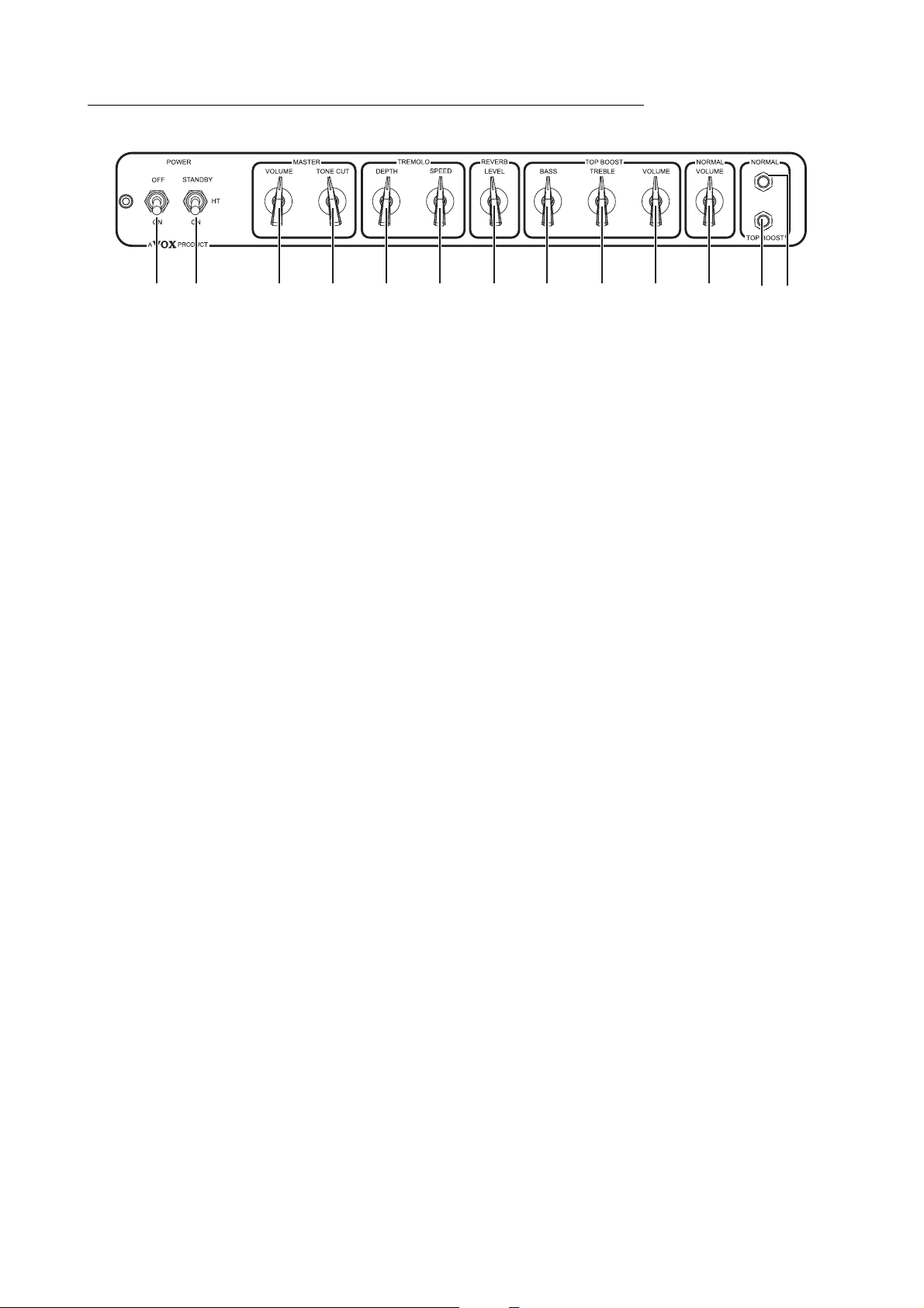
AC30C2(X)/AC30CH FRONT PANEL LAYOUT
12 4356
98
10
7
11 1312
14
INPUTS
1. NORMAL jack
2. TOP BOOST
jack Plugging your guitar into this input will route your signal through the TOP BOOST
NORMAL
3. VOLUME control
NOTE!
TOP BOOST
NOTE!
Plugging your guitar into this input will route your signal through the NORMAL
channel. Top jack for high Input, and bottom jack for low input.
channel. Top jack for high Input, and bottom jack for low input.
This determines the sensitivity of the preamp section in the NORMAL channel.
Depending on where this is set, you can either blend in more gain by turning it
clockwise or you can turn it anticlockwise for a cleaner sound. The NORMAL
volume can be used in conjunction with the MASTER volume which will allow you
to get the perfect balance between distortion and overall volume. I.e. if you keep
the NORMAL volume low and the MASTER volume high, you will get a clean
sound at a high volume. Conversely, if you keep the NORMAL volume high and
the MASTER volume low you will get more distortion at a lower overall volume.
Because of the nature of the design of this amplifier, it may take a few minutes
until the circuit becomes stable after the power is turned on. Some noise might
occur during this time but it soon disappears.
The tone controls on the TOP BOOST channel are very interactive, eg increasing
the level of the TREBLE control will cut the BASS level. It is best to begin with the
Tone controls at 12 o’clock and experiment to find your perfect tone.
4. VOLUME control
NOTE!
5. TREBLE control
6. BASS control
6
This determines the sensitivity of the preamp section in the TOP BOOST channel. Depending on where this is set, you can either blend in more gain by turning it clockwise or you
can set it lower for a cleaner, “chimey” sound. The TOP BOOST Volume can be used in
conjunction with the MASTER volume which will allow you to get the perfect balance
between distortion and overall volume. I.e. If you keep the TOP BOOST volume low and
the MASTER volume high, you will get a clean sound at a high volume. Conversely, if you
keep the TOP BOOST volume high and the MASTER volume low you will get more distortion at a lower overall volume.
Because of the nature of the design of this amplifier, it may take a few minutes
until the circuit becomes stable after the power is turned on. Some noise might
occur during this time but it soon disappears.
This controls the high frequencies in your sound—from soft and round when
turned down (counterclockwise) to bright and cutting when cranked (clockwise)
and all points in-between.
This controls the low frequencies in your sound—from thin and light when turned
Page 7

down (counterclockwise) to warm and heavy when turned up full (clockwise) and
all points in-between.
REVERB
This section allows you to control the Reverb for both channels by adjusting the Tone and Level. You
can remotely switch the reverb On or Off with the Optional VFS2A Foot Switch.
7. TONE control
8. LEVEL control
This controls the high and low frequencies of the REVERB. You can make the
REVERB sound brighter by turning this control clockwise or you can make the
sound darker by turning it counterclockwise.
Experiment with this control to see which settings work best for you.
This controls the mix (amount) of REVERB in your sound. Turning this knob fully
clockwise will give you a wet, saturated sound while counterclockwise will give
you a drier sound.
TREMOLO
This section allows you to control the TREMOLO for both channels on this amplifier by adjusting the Speed
and Depth. You can remotely switch the TREMOLO on or off with the Optional VFS2A Foot Switch.
9. SPEED control
10. DEPTH control
What is TREMOLO?
Tremolo is a Vintage Guitar Amplifier effect that hails from the Brit invasion during the 60’s. Essentially it’s like having someone
sat next to your amplifier turning the master volume up and down! Having the Depth Control set to maximum will give a very
dramatic effect, making your guitar sounding very choppy, you can adjust how quickly the volume is turned up and down with
the speed control. Best thing to do is experiment to find your perfect sound.
As you might have guessed, this controls the SPEED of the built-in TREMOLO.
This controls the DEPTH (intensity) of the built-in TREMOLO.
MASTER
11. TONE CUT control
12. VOLUME control
POWER
13. STANDBY Switch
This circuit is placed in the power amp as opposed to the preamp section like the
TREBLE and BASS controls. What this does is the opposite of what you may
think. Turning it clockwise will decrease the higher frequencies and turning it
counterclockwise will add higher frequencies.
This controls the overall (MASTER) VOLUME of your amplifier. Cleaner sounds
can be achieved by lowering the NORMAL or TOP BOOST volumes and raising
the MASTER. Setting the MASTER lower and the NORMAL and TOP BOOST
volumes higher will give you a fatter, more distorted tone at a lower volume.
As with all the controls of this amplifier, please experiment with different configurations to find the tones that fit your playing style.
This switch allows the amplifier to attain the correct working temperature before
applying the H.T. supply. Before connecting the amplifier to the Mains supply,
ensure the Power and STANDBY switches are in the off position. Turn on the
POWER switch first and then wait 2–3 minutes before turning on the STANDBY
switch. Doing this each time you play helps prolong tube life.
The STANDBY switch is also very useful for playing live as it allows you to keep
the valves at a functional temperature between sets.
14. POWER Switch
This is the ON/OFF switch for the power to the amplifier. Please ensure the ampli-
fier is switched off and unplugged before being moved.
7
Page 8
AC15C1(X)/AC15C2/AC15CH FRONT PANEL LAYOUT
12 3 4 5
87
9
6
10 11
12 13
POWER
1. POWER Switch
2. STANDBY Switch
This is the ON/OFF switch for the power to the amplifier. Please ensure the ampli-
MASTER
3. VOLUME control
4. TONE CUT control
This controls the overall (MASTER) VOLUME of your amplifier. Cleaner sounds
fier is switched off and unplugged before being moved.
This switch allows the amplifier to attain the correct working temperature before
applying the H.T. supply. Before connecting the amplifier to the Mains supply,
ensure the Power and STANDBY switches are in the off position. Turn on the
POWER switch first and then wait 2–3 minutes before turning on the STANDBY
switch. Doing this each time you play helps prolong tube life. The STANDBY
switch is also very useful for playing live as it allows you to keep the valves at a
functional temperature between sets.
can be achieved by lowering the NORMAL or TOP BOOST volumes and raising
the MASTER. Setting the MASTER lower and the NORMAL and TOP BOOST
volumes higher will give you a fatter, more distorted tone at a lower volume.
As with all the controls of this amplifier, please experiment with different configurations to find the tones that fit your playing style.
This circuit is placed in the power amp as opposed to the preamp section like the
TREBLE and BASS controls. What this does is the opposite of what you may
think. Turning it clockwise will decrease the higher frequencies and turning it
counterclockwise will add higher frequencies.
TREMOLO
This section allows you to control the TREMOLO for both channels on this amplifier by adjusting the
Speed and Depth. You can remotely switch the TREMOLO on or off with the Optional VFS2A Foot
Switch.
5. DEPTH control
6. SPEED control
What is TREMOLO?
Tremolo is a Vintage Guitar Amplifier effect that hails from the Brit invasion during the 60’s. Essentially
it’s like having someone sat next to your amplifier turning the master volume up and down! Having
the Depth Control set to maximum will give a very dramatic effect, making your guitar sounding very
choppy, you can adjust how quickly the volume is turned up and down with the speed control. Best
thing to do is experiment to find your perfect sound.
8
This controls the DEPTH (intensity) of the built-in TREMOLO.
As you might have guessed, this controls the SPEED of the built-in TREMOLO.
Page 9

REVERB
This section allows you to control the Reverb for both channels by adjusting the Level. You can
remotely switch the reverb On or Off with the Optional VFS2A Foot Switch.
7. LEVEL control
TOP BOOST
NOTE!
8. BASS control
9. TREBLE control
10. VOLUME control
NOTE!
This controls the mix (amount) of REVERB in your sound. Turning this knob fully
clockwise will give you a wet, saturated sound while counterclockwise will give
you a drier sound.
The tone controls on the TOP BOOST channel are very interactive, eg increasing
the level of the TREBLE control will cut the BASS level. It is best to begin with the
Tone controls at 12 o’clock and experiment to find your perfect tone.
This controls the low frequencies in your sound—from thin and light when turned
down (counterclockwise) to warm and heavy when turned up full (clockwise) and
all points in-between.
This controls the high frequencies in your sound—from soft and round when
turned down (counterclockwise) to bright and cutting when cranked (clockwise)
and all points in-between.
This determines the sensitivity of the preamp section in the TOP BOOST channel.
Depending on where this is set, you can either blend in more gain by turning it clockwise or you can set it lower for a cleaner, “chimey” sound. The TOP BOOST Volume
can be used in conjunction with the MASTER volume which will allow you to get the
perfect balance between distortion and overall volume. I.e. If you keep the TOP
BOOST volume low and the MASTER volume high, you will get a clean sound at a
high volume. Conversely, if you keep the TOP BOOST volume high and the MASTER
volume low you will get more distortion at a lower overall volume.
Because of the nature of the design of this amplifier, it may take a few minutes
until the circuit becomes stable after the power is turned on. Some noise might
occur during this time but it soon disappears.
NORMAL
11. VOLUME control
NOTE!
INPUTS
12. TOP BOOST jack
13. NORMAL jack
This determines the sensitivity of the preamp section in the NORMAL channel.
Depending on where this is set, you can either blend in more gain by turning it
clockwise or you can turn it anticlockwise for a cleaner sound. The NORMAL
volume can be used in conjunction with the MASTER volume which will allow you
to get the perfect balance between distortion and overall volume. I.e. if you keep
the NORMAL volume low and the MASTER volume high, you will get a clean
sound at a high volume. Conversely, if you keep the NORMAL volume high and
the MASTER volume low you will get more distortion at a lower overall volume.
Because of the nature of the design of this amplifier, it may take a few minutes
until the circuit becomes stable after the power is turned on. Some noise might
occur during this time but it soon disappears.
Plugging your guitar into this input will route your signal through the TOP BOOST
channel.
Plugging your guitar into this input will route your signal through the NORMAL
channel.
9
Page 10
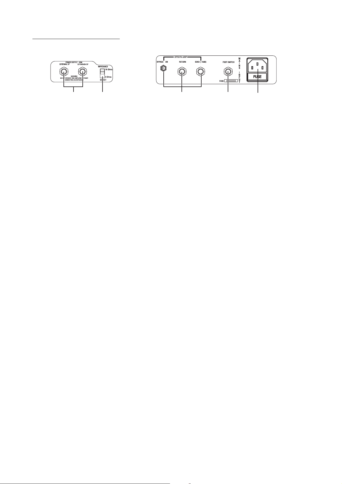
REAR PANEL LAYOUT
(AC30C2(X)/AC30CH)
412 3 5
1. POWER OUTPUT Jacks
COMBOS
This is where you can hook up an extension or external speaker cabinet(s) if
desired.
EXTENSION SP:
are wired for 16 Ohms. The extension cabinet must be 16 Ohms.
EXTERNAL SP:
you can hook up either a 16 Ohm or 8 Ohm cabinet. Be sure to set the Output
Select switch accordingly.
NOTE!
Hooking up a cabinet through the External jack will mute (disconnect) the internal
speakers!
HEAD
LOUDSPEAKER:
You can connect one or two 16 Ohm cabinets. You can only connect one 8 ohm
cabinet.
Be sure to set the IMPEDANCE SELECT switch accordingly.
This speaker jack runs parallel with the internal speakers which
This speaker jack will mute (disconnect) the internal speakers and
The two LOUDSPEAKER Jacks are connected in parallel.
WARNING!
NOTE!
2. IMPEDANCE Select switch
To ensure that your system works correctly, you must observe the following
points.
a) Don’t use an extension cabinet whose impedance is other than 16 Ohms.
b) Don’t connect a speaker whose rated input capacity is less than 30 watts (for
AC30C2(X)/AC30CH) or 15 watts (AC15C2/AC15C1(X)/AC15CH). The speaker
may be destroyed if you ignore this caution—not recommended!
c) You must use a speaker cable to connect an external speaker. Don’t use a
shielded cable like the one you use to connect a guitar to an amp.
d) You must turn off the power before connecting the cable. Connecting the cable
while the power is turned on may damage your amp.
It is recommended that all audio cables, with the exception of the speaker lead,
used to connect to the AC30C2(X)/AC15C2/AC15C1(X)/AC30CH of a high qual-
ity, screened type.
These should not exceed 10 metres in length. Always use a non-screened
speaker lead with the AC30C2(X)/AC15C2/AC15C1(X)/AC15CH Amplifier and
extension cabinets.
16 OHMS:
COMBOS
Combos allow for the following configurations:
1) Set it to this if you use the internal speakers only.
2) Set it to this if you connect an external 16 Ohm speaker cabinet through the
External jack.
HEAD
1) Set it to this if you connect an external 16 Ohm speaker cabinet through the
LOUDSPEAKER jack.
8 OHMS:
COMBOS
Combos allow for the following configurations:
10
Page 11

1) Set it to this if you connect an extension cabinet through the Extension jack.
You’ll be running the internal and external speakers in parallel. The impedance of
the extension cabinet must be 16 Ohms.
2) Set it to this if you connect an external 8 Ohm speaker cabinet through the
External jack.
HEAD
1) Set it to this if you connect two external 16 Ohm speaker cabinets.
2) Set it to this if you connect an external 8 Ohm speaker cabinet through the
LOUDSPEAKER jack.
3. EFFECTS LOOP jack
NOTE!
4. FOOT SWITCH jack
5. MAINS INPUT connector
(AC30C2(X)/AC30CH)
The EFFECTS LOOP allows effects to be added further down the signal chain,
rather than just plugging them in line with your guitar and amplifier. By using the
Effects loop with Delay stomp boxes, for example, will prevent any strange distortions to the time delayed repetitions.
Please note that the EFFECTS LOOP sends at -10dB meaning it is suitable for
stomp boxes.
BYPASS ON/OFF:
“BYPASS” position, absolutely none of your original signal will be running through
until it’s switched “ON”.
RETURN:
the output of your effect(s).
Be sure to use shielded guitar cables only! NEVER use unshielded speaker cables.
SEND:
input of your effect(s).
This is where you connect the Optional VFS2A Foot Switch so you can turn the
REVERB and TREMOLO on and off.
This is where the supplied, detachable Mains (power) cord is connected. The specific
mains input voltage rating that your amplifier needs to run at is located on the rear panel
of your amplifier. Before making any connections or powering up the amplifier, make sure
the correct voltage is set. If you have any doubt, refer to your local VOX dealer.
This is a true bypass effects loop which means if this is set in the
Think of this as the “input” of the effects loop and will be connected to
Think of this as the “output” of the FX loop and will be connected to the
6. Attenuator
What is a Reactive Attenuator?
Our Reactive Attenuator design allows for a truer tone even at attenuated output volumes. This is
achieved by using our proprietary Reactor technology to allow the speaker and the amplifier interact
with one another, even with a resistive load (the attenuator) in line. This means the amplifier and
speaker behave the same way as a non-attenuated amplifier, with resonant peaks and troughs. What
this simply means to you is great tone, without the volume.
(AC30CH/AC15CH)
The AC30CH/AC15CH has a built in Reactive Attenuator. This enables you to keep the
great sounds of a driven AC30CH/AC15CH at more ear friendly volumes.
AC30CH
There are 3 settings, 30W (BYPASS), 3W (-10dB Attenuation) and 1/3W (-20dB Attenuation).
AC15CH
There are 3 settings, 15W (Bypass), 1.5W (-10dB Attenuation) and 1/6W (-20dB Attenuation).
NOTE!
When the IMPEDANCE Switch is set to 8Ohms the attenuator does not work.
11
Page 12
SPECIFICATION
AC30C2X AC30C2/AC30C2-TV
Dimensions
(W x D x H)
Weight 33.4 kg / 73.59 lbs. AC30C2: 32.2 kg / 70.99 lbs. AC30C2-TV: 31.0 kg / 68.34 lbs.
Output Power 30 Watts RMS into 16 Ohms 30 Watts RMS into 16 Ohms
Speaker 2 x 12" 8 ohm Celestion Alnico Blue 2 x 12" 8 ohm Celestion G12M Greenback
Inputs Normal input jack (high and low), Top
Outputs External loudspeaker jack, Extension
Options VFS2A Footswitch VFS2A Footswitch
702 x 265 x 556 mm / 27.64 x 10.43 x
21.89 inches
Boost input jack (high and low), FX
RETURN jack, Footswitch jack
loudspeaker jack, FX SEND jack
AC30C2: 702 x 265 x 556 mm / 27.64 x 10.43 x 21.89 inches
AC30C2-TV: 703 x 263 x 562 mm / 27.68 x 10.35 x 22.13 inches
Normal input jack (high and low), Top Boost input jack (high and
low), FX RETURN jack, Footswitch jack
External loudspeaker jack, Extension loudspeaker jack, FX SEND
jack
AC15C1X AC15C2 AC15C1/AC15C1-TV
Dimensions
(W x D x H)
Weight 22.6 kg / 49.82 lbs. 30.2 kg / 66.58 lbs. AC15C1:22 kg / 48.50 lbs.
602 x 265 x 456 mm / 23.70 x
10.43 x 17.95 inches
702 x 265 x 556 mm / 27.64 x
10.43 x 21.89 inches
AC15C1: 602 x 265 x 456 mm / 23.70 x
10.43 x 17.95 inches
AC15C1-TV: 605 x 263 x 468 mm / 23.82 x
10.35 x 18.43 inches
AC15C1-TV:21.3 kg / 46.96 lbs.
Output Power: 15 Watts RMS into 16 Ohms 15 Watts RMS into 16 Ohms 15 Watts RMS into 16 Ohms
Speaker 1 x 12" 15 ohm Celestion
Alnico Blue
Inputs Normal input jack, Top Boost
input jack, Footswitch jack
Outputs External loudspeaker jack,
Extension loudspeaker jack
Options VFS2A Footswitch VFS2A Footswitch VFS2A Footswitch
2 x 12" 8 ohm Celestion G12M
Greenback
Normal input jack, Top Boost
input jack, Footswitch jack
External loudspeaker jack,
Extension loudspeaker jack
1 x 12" 16 ohm Celestion G12M Greenback
Normal input jack, Top Boost input jack,
Footswitch jack
External loudspeaker jack, Extension loudspeaker jack
AC30CH AC15CH V212C
Dimensions
(W x D x H)
Weight 18.8 kg / 41.45 lbs. 15.3 kg / 33.73 lbs. 22.5 kg / 49.60 lbs.
Output Power 30 Watts RMS into 16 Ohms 15 Watts RMS into 16 Ohms ------------
Speaker ------------- ------------
Inputs Normal input jack (high and
705 x 266 x 284 mm / 27.76 x
10.47x 11.18 inches
low), Top Boost input jack
(high and low), FX RETURN
jack, Footswitch jack
610 x 266 x 284 mm / 24.02 x
10.47 x 11.18 inches
Normal input jack, Top Boost
input jack, Footswitch jack
705 x 268 x 571 mm / 27.76 x 10.55 x
22.48 inches
2 x 12" 8 ohm Celestion G12M Greenback
LOUDSPEAKER Input jack
Outputs 2x LOUDSPEAKER jack, FX
SEND jack
Options VFS2A Footswitch VFS2A Footswitch
*Specifications and appearance are subject to change without notice for improvement.
2x LOUDSPEAKER jack --------------
12
Page 13

13
Page 14
INFORMATIONS IMPORTANTES DE SECURITE
• Lisez attentivement ces instructions.
• Veuillez conserver ces instructions.
• Observez tous les avertissements.
• Suivez toutes les consignes à la lettre.
• N’utilisez jamais cet appareil dans un endroit humide ni à
proximité d’eau.
• L’appareil alimenté par courant électrique ne peut pas être
exposé à des éclaboussures; évite en outre de placer des
récipients contenant des liquides, comme un vase (ou un
verre de bière), sur l’appareil.
• Nettoyez uniquement l’appareil avec un chiffon doux et sec.
• Ne bloquez jamais les orifices de ventilation de l’appareil et
installez-le toujours conformément aux instructions du
fabricant.
• N’installez jamais l’appareil à proximité d’une source de
chaleur, telle que des radiateurs, poêles ou tout autre
dispositif (y compris des amplificateurs) générant de la
chaleur.
• N’essayez jamais de contourner le dispositif de sécurité d’une
prise de type polarisée ou d’une prise de terre. Une prise dite
polarisée dispose de deux broches, dont l’une est plus large
que l’autre. Une prise de terre comporte trois broches, dont
une de mise à la terre. Cette broche plus large ou broche de
mise à la terre vise à assurer votre sécurité. Si la fiche du
cordon d’alimentation ne correspond pas au type de prise de
courant de votre région, faites remplacer la prise obsolète par
un électricien qualifié (pour les Etats-Unis et le Canada).
• Placez toujours le cordon d’alimentation de sorte qu’on ne
risque pas de marcher dessus ni de le pincer. Cette
précaution vise tout spécialement la fiche du cordon et sa
sortie de l’appareil.
• Utilisez exclusivement les fixations/accessoires préconisés
par le fabricant.
• S’il y a risque d’orage ou que vous ne comptez pas utiliser
l’appareil pendant une période prolongée, débranchez-le du
secteur.
• La mise sur OFF de l’interrupteur d’alimentation n’isole pas
totalement ce produit de la ligne secteur; aussi, retirez la fiche
de la prise s’il doit rester inutilisé pendant une période
prolongée.
• Installez ce produit près de la prise électrique murale et
gardez un accès facile à la prise électrique et au cordon
d’alimentation.
• ATTENTION: Cet appareil doit absolument être connecté à
une prise électrique reliée à la terre.
• Confiez tout travail de réparation uniquement à un S.A.V.
qualifié. Faites appel au S.A.V. si l’appareil a subi tout
endommagement, comme par exemple si sa fiche secteur ou
son cordon d’alimentation sont endommagés, si de l’eau ou
des objets ont pénétré à l’intérieur de l’appareil, si celui-ci a
été exposé à la pluie ou à la moisissure, s’il est tombé ou
présente tout signe de dysfonctionnement.
• N’utilisez jamais d’allonge trop longue avec cet appareil et ne
l’alimentez jamais via les prises secteur équipant d’autres
dispositifs.
• N’installez jamais cet appareil dans un endroit confiné comme
une caisse de transport ou tout autre récipient similaire.
• Des niveaux d’écoute trop importants lors de l’utilisation d’un
casque ou d’écouteurs peuvent entraîner des pertes
d’audition.
• Utilisez l’appareil uniquement avec le chariot, stand, trépied,
fixation ou table spécifiés par le fabricant ou fourni avec
l’appareil. Si vous avez placé l’appareil sur un chariot, soyez
très prudent quand vous déplacez le chariot, afin d’éviter une
chute et des blessures.
• Cet instrument est conçu pour être utilisé dans des régions au
• Veillez à ne jamais bloquer les orifices de ventilation en les
• Ne placez aucune source de flamme nue, telle qu’une bougie
* Tous les noms de produits et de sociétés sont des marques
climat tempéré et ne convient pas pour les pays au climat
tropical.
couvrant d’objets tels que des journaux, nappes, rideaux, etc.
allumée, sur l’instrument.
L’éclair dans le triangle est un symbole destiné à
attirer l’attention de l’utilisateur sur la présence de
parties non isolées et de “tension dangereuse” à
l’intérieur de l’appareil, qui posent des risques
d’électrocution pour l’utilisateur.
Le point d’exclamation dans un triangle est un
symbole destiné à attirer l’attention de
l’utilisateur sur des sections de ce manuel
contenant des informations importantes, liées
à l’utilisation et à l’entretien de ce produit.
Note concernant les dispositions (Seulement EU)
Quand un symbole avec une poubelle barrée d’une
croix apparait sur le produit, le mode d’emploi, les
piles ou le pack de piles, cela signifie que ce produit,
manuel ou piles doit être déposé chez un
représentant compétent, et non pas dans une
poubelle ou toute autre déchetterie conventionnelle.
Disposer de cette manière, de prévenir les dommages
pour la santé humaine et les dommages potentiels pour
l'environnement. La bonne méthode d'élimination dépendra
des lois et règlements applicables dans votre localité, s’il vous
plaît, contactez votre organisme administratif pour plus de
détails. Si la pile contient des métaux lourds au-delà du seuil
réglementé, un symbole chimique est affiché en dessous du
symbole de la poubelle barrée d’une croix sur la pile ou le
pack de piles.
commerciales ou déposées de leur détenteur respectif.
14
Page 15

INTRODUCTION
Félicitations pour votre achat de l'amplificateur de guitare VOX Custom Series AC30C2X/AC30C2/
AC30C2-TV/AC15C1X/AC15C2/AC15C1/AC15C1-TV / de la tête d'ampli de guitare VOX Custom
Series AC30CH/AC15CH / du baffle V212C.
Cet ampli est l'aboutissement de plus de 50 ans d'expertise dans la conception et la fabrication
d'amplis guitare de haute qualité. Nous avons pris les meilleurs modèles AC et leur avons ajouté un
certain nombre de caractéristiques utiles pour vous offrir l'AC ayant la plus grande polyvalence
sonore à ce jour !
Nous sommes sûrs que vous trouverez ces améliorations extrêmement utiles et que votre nouvel
amplificateur vous apportera de nombreuses heures de plaisir sonore. Votre AC30 est équipé d'un
grand nombre de caractéristiques modernes et pratiques comme une véritable boucle d'effets
bypass, un volume général et des hauts-parleurs Celestion Blue Alnico (sur l'AC30C2X/AC15C1X
uniquement), pour n'en citer que quelques unes. Veuillez lire attentivement ce mode d'emploi pour
vous familiariser avec elles.
L'AC15C1X/AC15C2/AC15C1/AC15C1-TV/AC15CH possède maintenant un canal NORMAL et un
canal TOP BOOST, et partage de nombreuses caractéristiques avec l'AC30C2X/AC30C2/AC30C2TV/AC30CH.
Tous les modèles sont équipés du Celestion G12M Greenback.
L'AC30CH/AC15CH vous propose le formidable éventail de sons AC dans une tête de format portable et pratique. Outre leur conformité aux spécifications standard AC30C2/AC15C1, les têtes intègrent un atténuateur réactif, pour des sons croustillants même à bas volume - un must pour vos
tympans.
Veuillez vous reporter aux instructions de l’AC30C2/AC15C1 dans le manuel de l’utilisateur concernant l’utilisation de l’AC30C2-TV/AC15C1-TV.
15
Page 16

AGENCEMENT DE LA FACE AVANT DE L'AC30C2(X)/AC30CH
12 4356
98
10
7
11 1312
14
INPUTS (ENTRÉES)
1. Prise NORMAL
2. Prise TOP BOOST
NORMAL
3. Commande VOLUME
NOTE !
De par la nature de son design, le circuit a besoin de quelques minutes pour se
Brancher votre guitare à cette entrée fera passer votre signal au travers du canal
NORMAL. Prise jack du haut pour une entrée de haut niveau, et prise jack du bas
pour une entrée de bas niveau.
Brancher votre guitare à cette entrée fera passer votre signal au travers du canal
TOP BOOST. Prise jack du haut pour une entrée de haut niveau, et prise jack du
bas pour une entrée de bas niveau.
Détermine la sensibilité de la section préampli du canal NORMAL. Avec ce réglage, vous
pouvez soit ajouter plus de gain en tournant le bouton dans le sens horaire soit obtenir un
son plus clair en le tournant en sens inverse. Le volume NORMAL peut être employé en
conjonction avec le volume MASTER, ce qui vous permet d'obtenir la balance parfaite
entre distorsion et volume général. C'est-à-dire que si vous réglez le volume NORMAL bas
et le volume MASTER haut, vous obtiendrez un son clair à fort volume. À l'opposé, si vous
réglez le volume NORMAL haut et le volume MASTER bas, vous obtiendrez plus de distorsion à un volume général plus bas.
stabiliser une fois l’ ampli mis en sous tension. Il se peut que vous entendiez des
bruits au cours de ce laps de temps, mais ils disparaitront tres rapidement.
TOP BOOST
NOTE !
4. Commande VOLUME
NOTE !
16
Les commandes de tonalité du canal TOP BOOST sont très interactives, ainsi par
exemple augmenter le niveau des aigus avec la commande TREBLE réduira le
niveau des graves (BASS). Il vaut mieux commencer avec les commandes de
tonalité en position 12 heures et expérimenter pour trouver votre son parfait.
Détermine la sensibilité de la section préampli du canal TOP BOOST. Avec ce
réglage, vous pouvez soit ajouter plus de gain en tournant le bouton dans le sens
horaire soit le tourner en sens inverse pour un son "carillonnant" plus clair. Le
volume TOP BOOST peut être employé en conjonction avec le volume MASTER,
ce qui vous permet d'obtenir la balance parfaite entre distorsion et volume général. C'est-à-dire que si vous réglez le volume TOP BOOST bas et le volume MASTER haut, vous obtiendrez un son clair à fort volume. À l'opposé, si vous réglez
le volume TOP BOOST haut et le volume MASTER bas, vous obtiendrez plus de
distorsion à un volume général plus bas.
De par la nature de son design, le circuit a besoin de quelques minutes pour se
stabiliser une fois l’ ampli mis en sous tension. Il se peut que vous entendiez des
bruits au cours de ce laps de temps, mais ils disparaitront tres rapidement.
Page 17

5. Commande TREBLE
Contrôle les hautes fréquences de votre son—d'un son doux et rond en position
basse (sens anti-horaire) à un son brillant et tranchant avec un réglage poussé à
fond (sens horaire) en passant par tous les intermédiaires.
6. Commande BASS
Contrôle les basses fréquences de votre son—d'un son ténu et léger en position
basse (sens anti-horaire) à un son chaud et lourd avec un réglage à fond (sens
horaire) en passant par tous les intermédiaires.
REVERB
Cette section vous permet de contrôler la Reverb pour les deux canaux en réglant les commandes
Tone (tonalité) et Level (niveau). Vous pouvez activer/désactiver la reverb au pied avec le pédalier
optionnel VFS2A.
7. Commande TONE
8. Commande LEVEL
Contrôle les hautes et basses fréquences de la REVERB. Vous pouvez rendre
plus brillant le son de la REVERB en tournant cette commande dans le sens
horaire ou plus feutré par une rotation anti-horaire.
Faites des essais avec cette commande pour trouver les réglages qui vous conviennent le mieux.
Contrôle le mixage (la quantité) de REVERB dans votre son. Tourner cette commande à fond dans le sens horaire vous donne un son saturé d'effet tandis qu'en
sens anti-horaire, vous obtenez un son plus sec (moins d'effet).
TREMOLO
Cette section vous permet de contrôler le TREMOLO pour les deux canaux de l'amplificateur en
réglant les commandes Speed (vitesse) et Depth (profondeur). Vous pouvez activer/désactiver le
TREMOLO au pied avec le pédalier optionnel VFS2A.
9. Commande SPEED
10. Commande DEPTH
Qu'est-ce que le TREMOLO ?
Le Tremolo est un effet d'ampli guitare vintage qui vient de la déferlante britannique des années 60.
Essentiellement, cela revient à avoir quelqu'un assis près de votre ampli et chargé de constamment
monter et baisser le volume master volume ! Avec la commande Depth au maximum, cela donne un
effet très spectaculaire, qui fait sonner votre guitare de façon très hachée, la vitesse à laquelle le
volume monte et descend se réglant avec la commande Speed. La meilleure chose à faire est de
l'essayer pour trouver votre son idéal.
Comme vous pouvez vous en douter, c'est la commande de vitesse du TREMOLO intégré.
Contrôle la profondeur (intensité) du TREMOLO intégré.
MASTER
11. Commande TONE CUT
Ce circuit est placé dans l'ampli de puissance contrairement aux commandes
TREBLE et BASS de la section préampli. Il fonctionne à l'inverse de ce que vous
pourriez imaginer. Tourner la commande dans le sens horaire réduit les plus
hautes fréquences et la tourner dans le sens anti-horaire rajoute les plus hautes
fréquences.
12. Commande VOLUME
Contrôle le VOLUME général (MASTER) de votre amplificateur. Les sons clairs
peuvent être obtenus en baissant les volumes NORMAL ou TOP BOOST et en
17
Page 18

montant le volume MASTER. Un réglage bas du volume MASTER et un réglage
haut des volumes NORMAL et TOP BOOST vous donneront un son plus gros,
avec plus de distorsion, même à bas volume.
Comme avec toutes les commandes de cet amplificateur, veuillez essayer différentes configurations pour trouver les sons qui conviennent à votre style de jeu.
POWER
13. Commutateur STANDBY
Ce commutateur permet à l'amplificateur d'atteindre la température de fonctionnement correcte avant de lui appliquer l'alimentation H.T. Avant de brancher
l'amplificateur à la prise secteur, assurez-vous que les commutateurs POWER et
STANDBY sont relevés (position off). Activez d'abord le commutateur POWER et
attendez 2–3 minutes avant d'activer le commutateur STANDBY. Faire cela
chaque fois que vous jouez prolonge l'espérance de vie des lampes.
Le commutateur STANDBY est aussi très utile sur scène car il vous permet de
conserver les lampes à température fonctionnelle entre vos différents passages.
14. Commutateur POWER
C'est l'interrupteur On/Off de l'alimentation électrique de l'amplificateur. Vérifiez
que l'amplificateur est bien éteint et débranché avant de le déplacer.
18
Page 19

AGENCEMENT DE LA FACE AVANT DE L'AC15C2/AC15C1(X)/AC15CH
12 3 4 5
87
9
6
10 11
12 13
POWER
1. Commutateur POWER
C'est l'interrupteur On/Off de l'alimentation électrique de l'amplificateur. Vérifiez
que l'amplificateur est bien éteint et débranché avant de le déplacer
2. Commutateur STANDBY
Ce commutateur permet à l'amplificateur d'atteindre la température de fonctionnement correcte avant de lui appliquer l'alimentation H.T. Avant de brancher
l'amplificateur à la prise secteur, assurez-vous que les commutateurs POWER et
STANDBY sont relevés (position off). Activez d'abord le commutateur POWER et
attendez 2–3 minutes avant d'activer le commutateur STANDBY. Faire cela
chaque fois que vous jouez prolonge l'espérance de vie des lampes. Le commutateur STANDBY est aussi très utile sur scène car il vous permet de conserver les
lampes à température fonctionnelle entre vos différents passages.
MASTER
3. Commande VOLUME
Contrôle le VOLUME général (MASTER) de votre amplificateur. Les sons clairs
peuvent être obtenus en baissant les volumes NORMAL ou TOP BOOST et en
montant le volume MASTER. Un réglage bas du volume MASTER et un réglage
haut des volumes NORMAL et TOP BOOST vous donneront un son plus gros,
avec plus de distorsion, même à bas volume.
Comme avec toutes les commandes de cet amplificateur, veuillez essayer différentes configurations pour trouver les sons qui conviennent à votre style de jeu.
4. Commande TONE CUT
Ce circuit est placé dans l'ampli de puissance contrairement aux commandes
TREBLE et BASS de la section préampli. Il fonctionne à l'inverse de ce que vous
pourriez imaginer. Tourner la commande dans le sens horaire réduit les plus hautes
fréquences et la tourner dans le sens anti-horaire rajoute les plus hautes fréquences.
TREMOLO
Cette section vous permet de contrôler le TREMOLO pour les deux canaux de l'amplificateur en
réglant les commandes Speed (vitesse) et Depth (profondeur). Vous pouvez activer/désactiver le
TREMOLO au pied avec le pédalier optionnel VFS2A.
5. Commande DEPTH
Contrôle la profondeur (intensité) du TREMOLO intégré.
19
Page 20

6. Commande SPEED
Qu'est-ce que le TREMOLO ?
Le Tremolo est un effet d'ampli guitare vintage qui vient de la déferlante britannique des années 60.
Essentiellement, cela revient à avoir quelqu'un assis près de votre ampli et chargé de constamment
monter et baisser le volume master volume ! Avec la commande Depth au maximum, cela donne un
effet très spectaculaire, qui fait sonner votre guitare de façon très hachée, la vitesse à laquelle le
volume monte et descend se réglant avec la commande Speed. La meilleure chose à faire est de
l'essayer pour trouver votre son idéal.
Comme vous pouvez vous en douter, c'est la commande de vitesse du TREMOLO intégré.
REVERB
Cette section vous permet de contrôler la Reverb pour les deux canaux en réglant la commande
Level (niveau). Vous pouvez activer/désactiver la reverb au pied avec le pédalier optionnel VFS2A.
7. Commande LEVEL
TOP BOOST
NOTE !
Les commandes de tonalité du canal TOP BOOST sont très interactives, ainsi par
8. Commande BASS
9. Commande TREBLE
10. Commande VOLUME
NOTE !
De par la nature de son design, le circuit a besoin de quelques minutes pour se
Contrôle le mixage (la quantité) de REVERB dans votre son. Tourner cette commande à fond dans le sens horaire vous donne un son saturé d'effet tandis qu'en
sens anti-horaire, vous obtenez un son plus sec (moins d'effet).
exemple augmenter le niveau des aigus avec la commande TREBLE réduira le
niveau des graves (BASS). Il vaut mieux commencer avec les commandes de
tonalité en position 12 heures et expérimenter pour trouver votre son parfait.
Contrôle les basses fréquences de votre son—d'un son ténu et léger en position
basse (sens anti-horaire) à un son chaud et lourd avec un réglage à fond (sens
horaire) en passant par tous les intermédiaires.
Contrôle les hautes fréquences de votre son—d'un son doux et rond en position
basse (sens anti-horaire) à un son brillant et tranchant avec un réglage poussé à
fond (sens horaire) en passant par tous les intermédiaires.
Détermine la sensibilité de la section préampli du canal TOP BOOST. Avec ce
réglage, vous pouvez soit ajouter plus de gain en tournant le bouton dans le sens
horaire soit le tourner en sens inverse pour un son "carillonnant" plus clair. Le
volume TOP BOOST peut être employé en conjonction avec le volume MASTER,
ce qui vous permet d'obtenir la balance parfaite entre distorsion et volume général. C'est-à-dire qu’avec un réglage bas du volume TOP BOOST et un réglage
haut du volume MASTER, vous obtiendrez un son clair à fort volume. À l'opposé,
avec un réglage haut du volume TOP BOOST et un réglage bas du volume MASTER, vous obtiendrez plus de distorsion à un volume général plus bas.
stabiliser une fois l’ ampli mis en sous tension. Il se peut que vous entendiez des
bruits au cours de ce laps de temps, mais ils disparaitront tres rapidement.
NORMAL
11. Commande VOLUME
20
Détermine la sensibilité de la section préampli du canal NORMAL. Avec ce réglage,
vous pouvez soit ajouter plus de gain en tournant le bouton dans le sens horaire soit
obtenir un son plus clair en le tournant en sens inverse. Le volume NORMAL peut
être employé en conjonction avec le volume MASTER, ce qui vous permet d'obtenir
la balance parfaite entre distorsion et volume général. C'est-à-dire que si vous
Page 21

NOTE !
INPUTS (ENTRÉES)
réglez le volume NORMAL bas et le volume MASTER haut, vous obtiendrez un son
clair à fort volume. À l'opposé, si vous réglez le volume NORMAL haut et le volume
MASTER bas, vous obtiendrez plus de distorsion à un volume général plus bas.
De par la nature de son design, le circuit a besoin de quelques minutes pour se
stabiliser une fois l’ ampli mis en sous tension. Il se peut que vous entendiez des
bruits au cours de ce laps de temps, mais ils disparaitront tres rapidement.
12. Prise TOP BOOST
13. Prise NORMAL
Brancher votre guitare à cette entrée fera passer votre signal au travers du canal
TOP BOOST.
Brancher votre guitare à cette entrée fera passer votre signal au travers du canal
NORMAL.
21
Page 22

AGENCEMENT DE LA FACE ARRIÈRE
(AC30C2(X)/AC30CH)
412 3 5
1. Prises de sortie de puissance POWER OUTPUT
COMBOS
C'est ici que vous pouvez brancher, si vous le désirez, un ou des baffles externes
de remplacement (External) ou supplémentaires (Extension).
EXTENSION SP: cette prise pour baffle fonctionne en parallèle avec les haut-parleurs
internes qui sont câblés pour 16 ohms. Le baffle supplémentaire doit être en 16 ohms.
EXTERNAL SP:
internes et vous pouvez y brancher un baffle 16 ohms ou 8 ohms. Veillez bien à
régler le sélecteur d'impédance en conséquence.
NOTE !
Brancher un baffle à la prise External SP coupe (débranche) les haut-parleurs
internes !
cette prise pour baffle coupe (débranche) les haut-parleurs
TÊTE
LOUDSPEAKER (BAFFLE):
Vous pouvez brancher un ou deux baffles de 16 ohms. Vous pouvez seulement
brancher un baffle de 8 ohms.
Veillez à régler le sélecteur d'impédance IMPEDANCE SELECT en fonction du
baffle branché.
AVERTISSEMENT !
NOTE !
Pour garantir un fonctionnement correct de votre système, vous devez respecter
les points suivants.
a)
N'utilisez pas de baffle supplémentaire (extension) d'une impédance autre que 16 ohms.
b)
Ne branchez pas de baffle d'une puissance admissible inférieure à 30 watts
(AC30C2(X)/AC30CH) ou 15 watts (AC15C2/AC15C1(X)/AC15CH). Le baffle peut
être détruit si vous ne respectez pas cette mise en garde — ce n’est pas recommandé !
c) Vous devez utiliser un câble de baffle pour brancher un baffle externe. N'utilisez
pas de câble blindé comme ceux reliant une guitare à un ampli.
d) Vous devez couper l'alimentation électrique avant de brancher le câble. Brancher
le câble avec l'ampli sous tension peut endommager celui-ci.
Pour les connexions de l'AC30C2(X)/AC15C2/AC15C1(X); il est recommandé
que tous les câbles audio, à l'exception du câble de baffle, soient de type blindé
et de haute qualité.
Ces valeurs ne doivent pas dépasser 10 mètres de longueur. Utilisez toujours une
prise de haut-parleur non contrôlée avec l’amplificateur AC30C2(X)/AC15C2/
AC15C1(X) et les boîtiers d’extension.
Les deux prises pour baffle sont reliées en parallèle.
2. IMPEDANCE Select
TÊTE
22
(sélecteur d'impédance)
16 ohms :
COMBOS
Les combos permettent les configurations suivantes :
1)Choisissez ce réglage si vous n'utilisez que les haut-parleurs internes.
2)Choisissez ce réglage si vous branchez un baffle externe 16 ohms à la prise
EXTERNAL SP.
1)Choisissez cette position si vous avez branché un baffle de 16 ohms à la prise
pour baffle.
Page 23

8 ohms :
COMBOS
Les combos permettent les configurations suivantes :
1) Choisissez ce réglage si vous branchez un baffle supplémentaire à la prise
Extension SP.
Vous ferez fonctionner en parallèle les haut-parleurs internes et externes. Le baffle supplémentaire doit avoir une impédance de 16 ohms.
2) Choisissez ce réglage si vous branchez un baffle externe 8 ohms à la prise
External SP.
TÊTE
1) Choisissez cette position si vous avez branché deux baffles externes de 16
ohms aux prises pour baffle.
2) Choisissez cette position si vous avez branché un baffle externe de 8 ohms à
la prise pour baffle.
3. EFFECTS LOOP
4. Prise FOOT SWITCH
5. MAINS INPUT
(AC30C2(X)/AC30CH)
NOTE !
Veillez bien à n'utiliser que des câbles de guitare blindés ! N'utilisez JAMAIS de
La boucle d'effets (EFFECTS LOOP) permet d'ajouter d'autres effets à la chaîne
du signal plutôt que de les insérer entre votre guitare et votre amplificateur. En
utilisant la boucle d'effets avec par exemple une pédale de Delay, vous éviterez
les distorsions étranges des répétitions retardées dans le temps.
Veuillez noter que la boucle d'effets EFFECTS LOOP envoie un signal de -10 dB
adapté aux pédales d'effet.
BYPASS ON/OFF :
position “BYPASS”, absolument rien de votre signal d'origine ne passe jusqu'à ce
que vous basculiez ce commutateur sur “ON”.
RETURN : c'est le “retour” de la boucle d'effets auquel se branche la sortie de vos effets.
câbles de baffle non blindés.
SEND : c'est le “départ” de la boucle d'effets auquel se branche l'entrée de vos effets.
C'est ici que vous brancherez le pédalier optionnel VFS2A vous permettant d'activer/désactiver au pied REVERB et TREMOLO.
C'est ici que se branche le cordon d'alimentation secteur détachable (fourni). La
tension d'alimentation nécessaire à votre amplificateur est indiquée en face
arrière de l'amplificateur. Avant de faire toute connexion ou de mettre l'amplificateur sous tension, assurez-vous d'avoir sélectionné la tension correcte. En cas de
doute quelconque, adressez-vous à votre revendeur VOX local.
c'est un véritable bypass de boucle d'effets, ce qui signifie qu'en
6. Atténuateur
Un atténuateur réactif, vous dites?
De par sa conception, notre atténuateur réactif produit un son plus fidèle même à bas volume. C'est
ici qu'intervient une technologie de réacteur développée par nos soins, et garantissant l'interaction
entre le haut-parleur et l'amplificateur, cela même en présence d'une résistance (notre atténuateur)
entre ceux deux éléments. Cela signifie que l'amplificateur et le haut-parleur se comportent comme
un ampli que rien ne vient museler, produisant pointes et creux de résonance. Et pour vous, concrètement, cela signifie tout simplement que le son est fantastique, même à bas volume.
(AC30CH/AC15CH)
L'AC30CH/AC15CH intègre un atténuateur réactif. Ce dispositif vous permet de bénéficier des formidables sons d'un AC30CH/AC15CH saturé à un volume raisonnable.
AC30CH
Vous disposez de 3 réglages: 30W (contournement), 3W (atténuation de -10dB)
et 1/3W (atténuation de -20dB).
AC15CH
Vous disposez de 3 réglages: 15W (contournement), 1.5W (atténuation de -10dB)
et 1/6W (atténuation de -20dB).
NOTE!
Quand le sélecteur d'impédance IMPEDANCE SELECT est réglé sur la position
8Ohms, le circuit d'atténuateur n'est pas actif.
23
Page 24

CARACTÉRISTIQUES TECHNIQUES
AC30C2X AC30C2/AC30C2-TV
Dimensions (L x P x H) 702 x 265 x 556 mm
Poids 33,4 kg 32,2 kg (AC30C2) / 31,0 kg (AC30C2-TV)
Puissance de sortie 30 watts RMS sous 16 ohms 30 watts RMS sous 16 ohms
Haut-parleurs 2 Celestion Alnico Blue 12" 8 ohms 2 Celestion G12M Greenback 12" 8 ohms
prise entrées NORMAL (haute et basse),
Entrées
Sorties
Option pédalier VFS2A pédalier VFS2A
prise entrées TOP BOOST (haute et basse),
prise de retour d'effets, prise pour pédalier
prise pour baffle externe, prise pour baffle
supplémentaire, prise de départ d'effets
702 x 265 x 556 mm (AC30C2) / 703 x 263 x 562 mm
(AC30C2-TV)
prise entrées NORMAL (haute et basse), prise
entrées TOP BOOST (haute et basse), prise de
retour d'effets, prise pour pédalier
prise pour baffle externe, prise pour baffle supplémentaire, prise de départ d'effets
AC15C1X AC15C2 AC15C1/AC15C1-TV
Dimensions (L x P x H) 602 x 265 x 456 mm 702 x 265 x 556 mm
Poids 22,6 kg 30,2 kg
Puissance de sortie 15 watts RMS sous 16 ohms 15 watts RMS sous 16 ohms 15 watts RMS sous 16 ohms
Haut-parleurs
1 Celestion Alnico Blue 12" 16
ohms
2 Celestion G12M Greenback 12" 8 ohms
602 x 265 x 456 mm (AC15C1) /
605 x 263 x 468 mm (AC15C1-TV)
22 kg (AC15C1) / 21.3 kg
(AC15C1-TV)
1 Celestion G12M Greenback 12"
16 ohms
prise entrée NORMAL, prise
Entrées
Sorties
Option pédalier VFS2A pédalier VFS2A pédalier VFS2A
entrée TOP BOOST, prise pour
pédalier
prise pour baffle externe, prise
pour baffle supplémentaire
prise entrée NORMAL, prise
entrée TOP BOOST, prise
pour pédalier
prise pour baffle externe, prise
pour baffle supplémentaire
prise entrée NORMAL, prise
entrée TOP BOOST, prise pour
pédalier
prise pour baffle externe, prise
pour baffle supplémentaire
AC30CH AC15CH V212C
Dimensions (L x P x H) 705 x 266 x 284 mm 610 x 266 x 284 mm 705 x 268 x 571 mm
Poids 18,8 kg 15,3 kg 22,5 kg
Puissance de sortie 30 watts RMS sous 16 ohms 15 watts RMS sous 16 ohms -------------------
Haut-parleurs ------------------- -------------------
prise entrées NORMAL
Entrées
Sorties
(haute et basse), prise
entrées TOP BOOST (haute
et basse), prise de retour
d'effets, prise pour pédalier
2 prises pour LOUDSPEAKER, prise de départ
d'effets
prise entrée NORMAL, prise
entrée TOP BOOST, prise
pour pédalier
2 prises pour LOUDSPEAKER
2 Celestion G12M Greenback 12" 8 ohms
prise entrée LOUDSPEAKER
-------------------
Option pédalier VFS2A pédalier VFS2A
*Les caractéristiques et l’aspect du produit sont susceptibles d’être modifiés sans avis préalable en vue d’une amélioration.
24
Page 25

25
Page 26

WICHTIGE SICHERHEITSHINWEISE
• Bitte lesen Sie sich alle Bedienhinweise durch.
• Bewahren Sie diese Bedienhinweise auf.
• Beachten Sie alle Warnungen.
• Befolgen Sie alle Instruktionen.
• Verwenden Sie dieses Gerät niemals in der Nähe von Wasser.
• Ein netzgespeistes Gerät darf niemals Regen- oder
Wassertropfen ausgesetzt werden. Außerdem darf man keine
Flüssigkeitsbehälter wie Vasen usw. darauf stellen.
• Reinigen Sie es ausschließlich mit einem trockenen Tuch.
• Versperren Sie niemals die Lüftungsschlitze und stellen Sie das
Gerät nur an Orten auf, die vom Hersteller ausdrücklich
empfohlen werden.
• Stellen Sie das Gerät niemals in die Nähe einer Wärmequelle,
z.B. eines Heizkörpers, Ofens oder eines anderen Wärme
erzeugenden Gerätes (darunter auch Endstufen).
• Versuchen Sie niemals, die polarisierte Leitung bzw. Erde
hochzulegen oder zu umgehen. Ein polarisierter Stecker ist mit
zwei flachen Stiften unterschiedlicher Breite versehen. Ein
Stecker mit Erdung weist zwei Stifte und eine Erdungsbuchse
auf. Wenn der beiliegende Stecker nicht in Ihre Steckdose
passt, sollten Sie einen Elektriker bitten, die Steckdose zu
erneuern (für die USA und Kanada).
• Sorgen Sie dafür, dass man weder über das Netzkabel stolpern
kann, noch dass es in unmittelbarer Nähe einer Steckdose,
darunter auch Zusatzsteckdosen anderer Geräte, abgeklemmt
wird. Auch am Austritt aus dem Gerät darf das Netzkabel auf
keinen Fall gequetscht werden.
• Verwenden Sie nur Halterungen/Zubehör, die/das vom
Hersteller ausdrücklich empfohlen werden/wird.
• Im Falle eines Gewitters bzw. wenn Sie das Gerät längere Zeit
nicht verwenden möchten, lösen Sie bitte den Netzanschluss.
• Durch Ausschalten des Hauptschalters wird dieses Erzeugnis
nicht vollständig vom Netz getrennt. Ziehen Sie deshalb den
Stecker des Netzkabels aus der Steckdose, wenn Sie das
Erzeugnis längere Zeit nicht verwenden.
• Stellen Sie diesen Verstärker in der Nähe einer Wand
Schutzkontaktdose auf und achten Sie auf die freie
Zugänglichkeit des Netzanschlusskabels.
• Warnhinweis: Dieser Verstärker darf nur an Steckdosen mit
Schutzleiter (Erdung) betrieben werden.
• Überlassen Sie alle Wartungsarbeiten einem erfahrenen
Wartungstechniker. Wartungsarbeiten oder Reparaturen sind
erforderlich, wenn das Netzkabel oder der Stecker beschädigt
ist, wenn Flüssigkeit oder andere Gegenstände in das
Geräteinnere gefallen sind, wenn das Gerät im Regen
gestanden hat, sich nicht erwartungsgemäß verhält oder wenn
es gefallen ist.
• Stellen Sie das Gerät niemals unmittelbar neben die Steckdose
und/oder Erweiterungssteckdose eines anderen Geräts.
• Stellen Sie das Gerät während des Betriebes niemals in einen
Türschrank oder den Lieferkarton.
• Hohe Schallpegel bei Verwendung eines großen oder kleinen
Kopfhörers können Hörschäden verursachen.
• Stellen Sie das Gerät nur auf einen Wagen, Ständer, Stative,
Halterungen oder Tische, die vom Hersteller ausdrücklich
empfohlen werden oder eventuell zum Lieferumfang gehören.
Seien Sie beim Verschieben eines geeigneten Wagens
vorsichtig, damit weder er, noch das Gerät selbst umkippt bzw.
hinfällt und Sie eventuell verletzt.
• Dieses Gerät ist für den Betrieb in gemäßigten Klimazonen
ausgelegt und nicht zur Verwendung in Ländern mit tropischem
Klima geeignet.
• Sorgen Sie stets für eine einwandfreie Lüftung, indem Sie die
Lüftungsöffnungen freihalten –Zeitungen, Tücher und andere
Gegenstände haben auf den Lüftungsöffnungen nichts
verloren!
• Stellen Sie niemals Gegenstände mit offener Flamme wie
brennende Kerzen, Wunderkerzen usw. auf das Gerät!
Der als Pfeil dargestellte Blitz in einem
Dreieck weist den Anwender auf nicht
isolierte, „gefährliche Spannungen“ im
Geräteinneren hin, die so stark sein können,
dass sie einen Stromschlag verursachen.
Das Ausrufezeichen in einem Dreieck weist
den Anwender darauf hin, dass zum
Lieferumfang des Gerätes wichtige Bedienund Wartungshinweise (eventuell
Reparaturhinweise) gehören.
Hinweis zur Entsorgung (Nur EU)
Wenn Sie das Symbol mit der „durchgekreuzten Mülltonne“ auf Ihrem Produkt, der dazugehörigen Bedienungsanleitung, der Batterie oder dem Batteriefach
sehen, müssen Sie das Produkt in der vorgeschriebenen Art und Weise entsorgen. Dies bedeutet, dass
dieses Produkt mit elektrischen und elektronischen
Komponenten nicht mit dem normalen Hausmüll entsorgt werden darf. Für Produkte dieser Art existiert ein separates, gesetzlich festgelegtes Entsorgungssystem.
Gebrauchte elektrische und elektronische Geräte müssen
separat entsorgt werden, um ein umweltgerechtes Recycling
sicherzustellen. Diese Produkte müssen bei benannten Sammelstellen abgegeben werden. Die Entsorgung ist für den
Endverbraucher kostenfrei! Bitte erkundigen sie sich bei ihrer
zuständigen Behörde, wo sie diese Produkte zur fachgerechten Entsorgung abgeben können.
Falls ihr Produkt mit Batterien oder Akkumulatoren ausgerüstet ist, müssen sie diese vor Abgabe des Produktes entfernen
und separat entsorgen (siehe oben). Die Abgabe dieses Produktes bei einer zuständigen Stelle hilft ihnen, dass das Produkt umweltgerecht entsorgt wird. Damit leisten sie
persönlich einen nicht unerheblichen Beitrag zum Schutz der
Umwelt und der menschlichen Gesundheit vor möglichen
negativen Effekten durch unsachgemäße Entsorgung von
Müll. Batterien oder Akkus, die Schadstoffe enthalten, sind
auch mit dem Symbol einer durchgekreuzten Mülltonne
gekennzeichnet. In der Nähe zum Mülltonnensymbol befindet
sich die chemische Bezeichnung des Schadstoffes.
Cd oder NiCd steht für Cadmium, Pb für Blei und Hg für
Quecksilber.
26
* Alle Produkt- und Firmennamen sind Warenzeichen oder
eingetragene Warenzeichen der betreffenden Eigentümer.
Page 27

VORWEG
Herzlichen Glückwunsch zu Ihrer Wahl eines VOX Custom-Combo-Gitarrenverstärkers.AC30C2X/
AC30C2/AC30C2-TV/AC15C1X/AC15C2/AC15C1/AC15C1-TV bzw. eines VOX Custom-Gitarrenverstärkers AC30CH/AC15CH / einer Lautsprecherbox V212C.
Dieser Verstärker stellt so etwas wie den Höhepunkt einer bereits 50 Jahre währenden Erfolgsgeschichte jener Firma dar, der man viel Fachwissen und noch mehr Spürsinnen für einen guten Sound
nachsagt. Für diesen Amp haben wir uns die besten AC-Schaltpläne geschnappt und die ursprünglichen Ideen um weitere praktische Funktionen ergänzt. Dieser AC ist eine der flexibelsten Ausführungen, die es je gab! Wir sind uns ziemlich sicher, dass Ihnen die Verbesserungen gefallen werden
und dass Sie Jahre lang Freude an Ihrem Verstärker haben werden. Ihr AC30 wartet mit einer ganzen
Reihe an modernen Ausstattungsmerkmalen und Annehmlichkeiten auf, True Bypass Effektschleife,
Master Volumen Regler und Original Celestion AlNiCo Blue Lautsprecher (nur bei AC30C2X/
AC15C1X), um nur die wichtigsten zu nennen. Bitte lesen Sie sich diese Bedienungsanleitung vollständig durch, um alle Funktionen kennen und lieben zu lernen.
Der AC15C1X/AC15C2/AC15C1/AC15C1-TV/AC15CH ist sowohl mit einem NORMAL- als auch
einem TOP BOOST-Kanal ausgestattet und übernimmt auch sonst mehrere Funktionen des
AC30C2X/AC30C2/AC30C2-TV/AC30CH.
Alle Modelle sind ab Werk mit einem Celestion G12M Greenback ausgestattet.
Der AC30CH/AC15CH bietet Ihnen den großartigen Sound der AC-Reihe im praktischen Head-Format. Neben den Standardeigenschaften des AC30C2/AC15C1 verfügen die Heads auch über einen
Reactive Attenuator für großartigen Sound bereits bei gehörschonender Zimmerlautstärke.
Wie man den AC30C2/AC15C1 bedient, erfahren Sie in der Bedienungsanleitung des AC30C2-TV/
AC15C1-TV.
27
Page 28

BEDIENFELD DES AC30C2(X)/AC30CH
12 4356
98
10
7
11 1312
14
INPUTS
1. NORMAL-Buchse
2.
TOP BOOST-Buchse
NORMAL
3. VOLUME-Regler
Achtung!
Wenn Sie Ihre Gitarre hier anschließen, wird ihr Signal vom NORMAL-Kanal
bearbeitet. Die obere Buchse ist für ein hochpegeliges und die untere für ein niedrigpegeliges Signal gedacht.
Wenn Sie Ihre Gitarre hier anschließen, wird ihr Signal vom TOP BOOST-Kanal bearbeitet. Die obere Buchse ist für ein hochpegeliges und die untere für ein niedrigpegeliges Signal gedacht.
Hiermit wird die Empfindlichkeit des NORMAL-Vorverstärkers eingestellt. Wenn Sie
ihn nach rechts drehen, wird der Pegel („Gain“) angehoben. Drehen Sie ihn nach
links, um einen „cleanen“ Sound zu erzielen. Die NORMAL-Lautstärke kann im
Zusammenspiel mit dem MASTER VOLUME-Regler eingestellt werden, um die
gewünschte Balance zwischen Übersteuerung und Lautstärke zu erzielen. Will heißen: Mit einem niedrigen NORMAL- und einem hohen MASTER VOLUME-Wert
erzielen Sie einen lauten „Clean“-Sound. Wählen Sie dagegen eine hohe NORMALLautstärke und einen niedrigen MASTER VOLUME-Wert, so erzielen Sie bereits bei
Schlafzimmerpegel eine herrlich geschmeidige Verzerrung.
Schaltungsbedingt kann es nach Einschalten des Verstarkers einige Minuten
dauern bis der Betriebszustand erreicht ist. Wahrenddessen konnen einige Storgerausche auftreten, die nach kurzer Zeit wieder nachlassen.
TOP BOOST
Achtung!
4. VOLUME-Regler
Achtung!
28
Die Klangregler des TOP BOOST-Kanals arbeiten interaktiv: Wenn Sie z.B. den
TREBLE-Pegel anheben, sinkt der BASS-Pegel. Am besten stellen Sie die
Klangregler anfangs in die „12 Uhr“-Position und erschrauben sich von da aus
den gewünschten Sound.
Hiermit wird die Empfindlichkeit des TOP BOOST-Vorverstärkers eingestellt.
Wenn Sie ihn nach rechts drehen, wird der Pegel („Gain“) angehoben. Drehen Sie
ihn nach links, um einen „glockigen“ Klang zu erzielen. Die TOP BOOST-Lautstärke kann im Zusammenspiel mit dem MASTER VOLUME-Regler eingestellt
werden, um die gewünschte Balance zwischen Übersteuerung und Lautstärke zu
erzielen. Will heißen: Mit einem niedrigen TOP BOOST- und einem hohen MASTER VOLUME-Wert erzielen Sie einen lauten „Clean“-Sound. Wählen Sie dagegen eine hohe TOP BOOST-Lautstärke und einen niedrigen MASTER VOLUMEWert, so erzielen Sie bereits bei Schlafzimmerpegel starke Verzerrung.
Schaltungsbedingt kann es nach Einschalten des Verstarkers einige Minuten
dauern bis der Betriebszustand erreicht ist. Wahrenddessen konnen einige Storgerausche auftreten, die nach kurzer Zeit wieder nachlassen.
Page 29

5. TREBLE-Regler
Hiermit können die Höhen angehoben und abgesenkt werden – von „geschmeidig und rund“ (ganz links) bis „beißend“ (ganz rechts).
6. BASS-Regler
Hiermit können die Bassfrequenzen angehoben und abgesenkt werden – von
„dünn und leicht“ (ganz links) bis „warm und fett“ (ganz rechts).
REVERB
In dieser Sektion kann der Halleffekt der beiden Kanäle eingestellt werden (Klangfarbe und Pegel).
Bei Bedarf kann der Hall mit dem optionalen VFS2A Fußtaster ein- und ausgeschaltet werden.
7. TONE-Regler
8. LEVEL-Regler
Hiermit können der Höhen- und Bassanteil des REVERB-Effekts geändert werden. Drehen Sie den Regler nach rechts, wenn Sie einen helleren REVERBSound bevorzugen bzw. nach links, um einen runderen Hall verwenden zu können. Am besten probieren Sie einfach mehrere Einstellungen aus.
Hiermit wird die Balance zwischen dem Direkt- und dem Hallsignal eingestellt.
Drehen Sie ihn ganz nach rechts, wenn Sie einen lauten Hall benötigen. Drehen
Sie ihn weiter nach links, wenn’s nicht ganz so stark hallen soll.
TREMOLO
Hier können Sie die Geschwindigkeit (SPEED) und Intensität (DEPTH) des Tremoloeffekts für beide
Kanäle einstellen. Bei Bedarf kann der Tremoloeffekt mit dem optionalen VFS2A Fußtaster ein- und
ausgeschaltet werden.
9. SPEED-Regler
10. DEPTH-Regler
Was genau ist ‘Tremolo’?
Viele britische Gitarrenverstärker der 1960er waren mit einem Tremoloeffekt ausgestattet. Dieser
Effekt entspricht in etwa dem regelmäßigen Erhöhen und Verringern des MASTER VOLUME-Wertes!
Je weiter Sie den DEPTH-Regler nach rechts drehen, desto intensiver wird die Lautstärke beeinflusst, was zu einem starken Zittern führt. Die Geschwindigkeit des Effekts kann mit dem SPEEDRegler eingestellt werden. Probieren Sie mehrere Einstellungen aus, um den für Ihre Musik passenden Effekt zu finden.
Hiermit regeln Sie die Tremologeschwindigkeit.
Hiermit stellen Sie die Tremolointensität ein.
MASTER
11. TONE CUT-Regler
12. VOLUME-Regler
Diese Schaltung befindet sich in der Endstufe (während TREBLE und BASS das
Vorverstärkersignal beeinflussen). Sie tut genau das Gegenteil dessen, was der
Name verspricht: Wenn Sie den Regler nach rechts drehen, werden die Höhen
abgesenkt. Drehen Sie ihn nach links, so werden die Höhen angehoben.
Hiermit kann die allgemeine Ausgangslautstärke des Amps eingestellt werden.
Um einen lauten „Clean“-Sound zu erzielen, müssen Sie diesen Regler aufdrehen und die NORMAL VOLUME- bzw. TOP BOOST VOLUME-Einstellung verringern. Um bei geringen Pegeln eine satte Verzerrung zu erzielen, müssen Sie
NORMAL VOLUME bzw. TOP BOOST VOLUME auf- und MASTER VOLUME
weiter zudrehen. Auch hier raten wir, ein wenig mit unterschiedlichen Varianten
zu experimentieren, um genau „Ihren“ Sound zu finden.
29
Page 30

POWER
13. STANDBY-Schalter
Hiermit sorgen Sie dafür, dass der Verstärker die richtige Betriebstemperatur
erreicht, bevor die Stromversorgung angeknipst wird. Stellen Sie vor dem
Anschließen oder Lösen des Netzkabels sowohl den POWER- als auch den
STANDBY-Schalter in die „OFF“- bzw. „STANDBY“-Position. Aktivieren Sie immer
zuerst den POWER-Schalter und warten Sie 2–3 Minuten, bevor Sie STANDBY
aktivieren. Damit verlängern Sie nämlich die Lebenserwartung der Röhren. Der
STANDBY-Schalter ist zudem für Live-Anwendungen praktisch, um zu verhindern, dass sich die Röhren in den Spielpausen zu stark abkühlen.
14. POWER-Schalter
Hiermit schalten Sie die Stromversorgung des Verstärkers ein und aus. Vor Lösen
des Netzanschlusses und dem anschließenden Transport müssen Sie den Amp
unbedingt ausschalten.
30
Page 31

BEDIENFELD DES AC15C2/AC15C1(X)/AC15CH
12 3 4 5
87
9
6
10 11
12 13
POWER
1. POWER-Schalter
2. STANDBY-Schalter
MASTER
3. VOLUME-Regler
4. TONE CUT-Regler
Hiermit schalten Sie die Stromversorgung des Verstärkers ein und aus. Vor Lösen
des Netzanschlusses und dem anschließenden Transport müssen Sie den Amp
unbedingt ausschalten.
Hiermit sorgen Sie dafür, dass der Verstärker die richtige Betriebstemperatur
erreicht, bevor er mit einer hohen Spannung versorgt wird. Stellen Sie vor dem
Anschließen oder Lösen des Netzkabels sowohl den POWER- als auch den
STANDBY-Schalter in die „OFF“- bzw. „STANDBY“-Position. Aktivieren Sie immer
zuerst den POWER-Schalter und warten Sie 2~3 Minuten, bevor Sie STANDBY
aktivieren. Damit verlängern Sie nämlich die Lebenserwartung der Röhren. Der
STANDBY-Schalter ist zudem für Live-Anwendungen praktisch, um zu verhindern, dass sich die Röhren in den Spielpausen zu stark abkühlen.
Hiermit kann die allgemeine Ausgangslautstärke des Amps eingestellt werden.
Um einen lauten „Clean“-Sound zu erzielen, müssen Sie diesen Regler aufdrehen und die NORMAL VOLUME- bzw. TOP BOOST VOLUME-Einstellung verringern. Um bei geringen Pegeln eine satte Verzerrung zu erzielen, müssen Sie
NORMAL VOLUME bzw. TOP BOOST VOLUME auf- und MASTER VOLUME
weiter zudrehen. Am besten experimentieren Sie ein wenig mit unterschiedlichen
Varianten, um genau „Ihren“ Sound zu finden.
Diese Schaltung befindet sich in der Endstufe (während TREBLE und BASS das
Vorverstärkersignal beeinflussen). Sie tut genau das Gegenteil dessen, was der
Name verspricht: Wenn Sie den Regler nach rechts drehen, werden die Höhen
abgesenkt. Drehen Sie ihn nach links, so werden die Höhen angehoben.
TREMOLO
Hier können Sie die Geschwindigkeit (SPEED) und Intensität (DEPTH) der Tremoloschaltung für
beide Kanäle einstellen. Bei Bedarf kann der Tremoloeffekt mit dem optionalen VFS2A Fußtaster einund ausgeschaltet werden.
5. DEPTH-Regler
6. SPEED-Regler
Was genau ist ‘Tremolo’?
Viele britische Gitarrenverstärker der 1960er waren mit einem Tremoloeffekt ausgestattet. Dieser Effekt entspricht in etwa dem regelmäßigen Erhöhen und Verringern des MASTER VOLUME-Wertes! Je weiter Sie den
DEPTH-Regler nach rechts drehen, desto intensiver wird die Lautstärke beeinflusst, was zu einem starken Zittern führt. Die Geschwindigkeit des Effekts kann mit dem SPEED-Regler eingestellt werden. Probieren Sie mehrere Einstellungen aus, um den für Ihre Musik passenden Effekt zu finden.
Hiermit stellen Sie die Tremolointensität ein.
Hiermit regeln Sie die Tremologeschwindigkeit.
31
Page 32

REVERB
In dieser Sektion kann der Hallanteil der beiden Kanäle eingestellt werden. Bei Bedarf kann der Hall
mit einem optionalen VFS2A Fußtaster ein- und ausgeschaltet werden.
7. LEVEL-Regler
TOP BOOST
Achtung!
8. BASS-Regler
9. TREBLE-Regler
10. VOLUME-Regler
Achtung!
Hiermit stellen Sie die Balance zwischen dem Direkt- und dem Hallsignal ein.
Drehen Sie ihn ganz nach rechts, wenn Sie einen lauten Hall benötigen. Drehen
Sie ihn weiter nach links, wenn’s nicht ganz so stark hallen soll.
Die Klangregler des TOP BOOST-Kanals arbeiten interaktiv: Wenn Sie z.B. den
TREBLE-Pegel anheben, sinkt der BASS-Pegel. Am besten stellen Sie die
Klangregler anfangs in die „12 Uhr“-Position und erschrauben sich von da aus
den gewünschten Sound.
Hiermit können die Bassfrequenzen angehoben und abgesenkt werden – von
„dünn und leicht“ (ganz links) bis „warm und fett“ (ganz rechts).
Hiermit können die Höhen angehoben und abgesenkt werden – von „geschmeidig und rund“ (ganz links) bis „beißend“ (ganz rechts).
Hiermit wird die Empfindlichkeit des TOP BOOST-Vorverstärkers eingestellt.
Wenn Sie ihn nach rechts drehen, wird der Pegel („Gain“) angehoben. Drehen Sie
ihn nach links, um einen „glockigen“ Klang zu erzielen. Die TOP BOOST-Lautstärke kann im Zusammenspiel mit dem MASTER VOLUME-Regler eingestellt
werden, um die gewünschte Balance zwischen Übersteuerung und Lautstärke zu
erzielen. Will heißen: Mit einem niedrigen TOP BOOST- und einem hohen MASTER VOLUME-Wert erzielen Sie einen lauten „Clean“-Sound. Wählen Sie dagegen eine hohe TOP BOOST-Lautstärke und einen niedrigen MASTER VOLUMEWert, so erzielen Sie bereits bei Schlafzimmerpegel starke Verzerrung.
Schaltungsbedingt kann es nach Einschalten des Verstarkers einige Minuten
dauern bis der Betriebszustand erreicht ist. Wahrenddessen konnen einige Storgerausche auftreten, die nach kurzer Zeit wieder nachlassen.
NORMAL
11. VOLUME-Regler
Achtung!
INPUTS
12. TOP BOOST-Buchse
13. NORMAL-Buchse
Hiermit wird die Empfindlichkeit des NORMAL-Vorverstärkers eingestellt. Wenn
Sie ihn nach rechts drehen, wird der Pegel („Gain“) angehoben. Drehen Sie ihn
nach links, um einen „cleanen“ Sound zu erzielen. Die NORMAL-Lautstärke kann
im Zusammenspiel mit dem MASTER VOLUME-Regler eingestellt werden, um
die gewünschte Balance zwischen Übersteuerung und Ausgangspegel zu erzielen. Will heißen: Mit einem niedrigen NORMAL- und einem hohen MASTER
VOLUME-Wert erzielen Sie einen lauten „Clean“-Sound. Wählen Sie dagegen
eine hohe NORMAL-Lautstärke und einen niedrigen MASTER VOLUME-Wert, so
erzielen Sie bereits bei Schlafzimmerpegel starke Verzerrung.
Schaltungsbedingt kann es nach Einschalten des Verstarkers einige Minuten
dauern bis der Betriebszustand erreicht ist. Wahrenddessen konnen einige Storgerausche auftreten, die nach kurzer Zeit wieder nachlassen.
Wenn Sie Ihre Gitarre hier anschließen, wird ihr Signal vom TOP BOOST-Kanal bearbeitet.
Wenn Sie Ihre Gitarre hier anschließen, wird ihr Signal vom NORMAL-Kanal bearbeitet.
32
Page 33

RÜCKSEITE
(AC30C2(X)/AC30CH)
412 3 5
1. POWER OUTPUT-Buchsen
COMBOS
Hier können Sie eine Erweiterungs- und/oder eine externe Box anschließen.
EXTENSION SP:
sprechern (16Ω) getrieben. Die Impedanz der externen Box muss 16Ω betragen.
EXTERNAL SP:
Lautsprecher stumm. Vergessen Sie nicht, den IMPEDANCE SELECT-Schalter
richtig einzustellen.
Achtung!
WARNUNG!
Achtung!
Wenn Sie an die EXTERNAL-Buchse ein Kabel anschließen, werden die internen
Lautsprecher stummgeschaltet!
HEAD
LOUDSPEAKER:
Sie können eine oder zwei 16-Ohm-Boxen anschließen, aber nur eine 8-Ohm-Box.
Achten Sie darauf, den IMPEDANCE SELECT-Schalter richtig einzustellen.
Das System funktioniert nur ordnungsgemäß, wenn Sie folgende Punkte beachten.
a) Es dürfen nur Boxen mit einer Impedanz von 16Ω angeschlossen werden.
b)
Verwenden Sie niemals eine Box mit einer Eingangskapazität von weniger als 30W
(beim AC30C2(X)/AC30CH) bzw. 15W (AC15C2/AC15C1(X)/AC15CH).
Lautsprecher, die diese Anforderungen nicht erfüllen, sind in kürzester Zeit kaputt!
c) Für die Verbindung der Box benötigen Sie ein Lautsprecherkabel. Geschirmte,
d.h. Gitarrenkabel eignen sich hierfür nicht.
d) Schalten Sie den Verstärker vor Anschließen der Box aus. Wenn Sie das nicht
tun, überlebt der Amp den Anschlussversuch eventuell nicht.
Prinzipiell sollten alle Kabel (bis auf die Lautsprecherkabel), die man an den
AC30C2(X)/AC15C2/AC15C1(X) anschließt, geschirmt und von guter Qualität sein.
Die Kabel sollten eine Länger von 10 Metern nicht überschreiten. Verwenden Sie
zum Anschluss einer Lautsprecherbox an den AC30C2(X)/AC15C2/AC15C1(X)-
Verstärker ausschließlich nicht geschirmte Lautsprecherkabel.
Eine hier angeschlossene Box wird parallel zu den internen Laut-
Eine hier angeschlossene Box (16Ω oder 8Ω) schaltet die internen
Die beiden LOUDSPEAKER-Buchsen sind parallel geschaltet.
2. IMPEDANCE SELECT
16Ω:
COMBOS
Combos können in folgenden Konfigurationen verwendet werden:
1)
Wählen Sie diese Einstellung, wenn Sie nur die internen Lautsprecher verwenden.
2) Wählen Sie diese Einstellung, wenn Sie eine 16Ω-Box an die EXTERNALBuchse angeschlossen haben.
HEAD
1)Wählen Sie diese Einstellung, wenn Sie eine 16-Ohm-Box an die LOUDSPEAKER-Buchse anschließen.
8Ω:
COMBOS
Combos können in folgenden Konfigurationen verwendet werden:
1) Wählen Sie diese Einstellung, wenn Sie eine Box an die EXTENSION-Buchse
33
Page 34

angeschlossen haben. Die internen Lautsprecher und die externe Box werden dann
parallel angesprochen. Die Impedanz der externen Box muss 16Ω betragen.
2) Wählen Sie diese Einstellung, wenn Sie eine 8Ω-Box an die EXTERNAL-
Buchse angeschlossen haben.
HEAD
1) Wählen Sie diese Einstellung, wenn Sie zwei 16-Ohm-Boxen an die LOUDSPEAKER-Buchse anschließen.
2) Wählen Sie diese Einstellung, wenn Sie eine 8-Ohm-Box an die LOUDSPEAKER-Buchse anschließen.
3. EFFECTS LOOP-Buchse
EFFECTS LOOP erlaubt das Einschleifen externer Effekte, die sich also nicht vor
dem Gitarreneingang zu befinden brauchen. Dieser Ansatz eignet sich z.B. für die
Verwendung eines Delay-Effekts, weil der ja in der Regel das bereits vom Amp
bearbeitete Signal beeinflussen und nicht selbst bearbeitet werden soll.
Die EFFECTS LOOP-Schleife verwendet einen Pegel von –10dB und eignet sich
daher auch für Effektpedale.
BYPASS ON/OFF:
Wenn Sie ihn auf „BYPASS“ stellen, wird die Effektschleife komplett umgangen.
Um letztere zu verwenden, müssen Sie die „ON“-Einstellung wählen.
RETURN:
Effektgerätes verbinden muss.
Achtung!
4. FOOT SWITCH-Buchse
5. MAINS INPUT
Hierfür dürfen nur geschirmte Gitarrenkabel verwendet werden! Benutzen Sie
niemals ungeschirmte Lautsprecherkabel.
SEND:
Effektgerätes verbinden muss.
Hier kann ein (optionaler) VFS2A Fußtaster angeschlossen werden, mit dem sich
der REVERB- und TREMOLO-Effekt ein- und ausschalten lassen.
Hier muss das beiliegende Netzkabel angeschlossen werden. Die vorausgesetzte Netzspannung wird auf der Geräterückseite erwähnt. Überprüfen Sie vor
Herstellen des Netzanschlusses und Einschalten des Verstärkers, ob er mit der
am Einsatzort angebotenen Netzspannung betrieben werden darf. Wenden Sie
sich im Zweifelsfall an Ihren VOX-Händler.
(AC30C2(X)/AC30CH)
Hierbei handelt es sich um einen „echten“ Bypass-Schalter:
Dies ist der Eingang der Effektschleife, den man mit dem Ausgang des
Dies ist der Ausgang der Effektschleife, den man mit dem Eingang des
6. Attenuator
Was tut der Reactive Attenuator?
Unser Reactive Attenuator Schaltkreis sorgt für einen authentischen Klang schon bei geringen Lautstärken. Dank unserer selbst entwickelten Reactor-Technologie können Lautsprecher und Verstärker
untereinander interagieren, auch wenn ein Widerstand (der Attenuator) dazwischen geschaltet ist.
Mit anderen Worten: Verstärker und Lautsprecher verhalten sich wie in einem voll aufgedrehten Verstärker, wo Resonanzspitzen und -Täler auftreten. Noch einfacher gesagt: Spitzenklang auch bei
Zimmerlautstärke.
(AC30CH/AC15CH)
Der AC30CH/AC15CH verfügt über einen Reactive Attenuator, der Ihnen den
großartigen Sound eines aufgerissenen AC30CH/AC15CH bereits bei gehörschonender Zimmerlautstärke bietet.
AC30CH
Es gibt 3 Einstellungen: 30W (BYPASS), 3W (-10dB Dämpfung) und 1/3W (-20dB
Dämpfung).
AC15CH
Es gibt 3 Einstellungen: 15W (BYPASS), 1,5W (-10dB Dämpfung) und 1/6W (20dB Dämpfung).
ACHTUNG!
Wenn der IMPEDANCE SELECT-Schaltet auf 8 Ohm steht, arbeitet der Attenuator nicht.
34
Page 35

TECHNISCHE DATEN
AC30C2X AC30C2/AC30C2-TV
Abmessungen (B x T x H) 702 x 265 x 556mm 702 x 265 x 556mm (AC30C2) / 703 x 263 x
Gewicht 33,4kg 32,2kg (AC30C2) / 31,0kg (AC30C2-TV)
Ausgangsleistung 30W RMS an 16Ω 30W RMS an 16Ω
Lautsprecher 2x 12" Celestion Alnico Blue (8Ω) 2x 12" Celestion G12M Greenback (8Ω)
Eingänge
Ausgänge External SP-Buchse, Extension SP-Buchse,
Sonderzubehör VFS2A-Fußtaster VFS2A-Fußtaster
NORMAL-Buchse („High“ und „Low“), TOP BOOSTBuchse („High“ und „Low“), EFFECT LOOP
RETURN-Buchse, FOOTSWITCH-Buchse
EFFECT LOOP SEND-Buchse
562mm (AC30C2-TV)
NORMAL-Buchse („High“ und „Low“), TOP BOOSTBuchse („High“ und „Low“), EFFECT LOOP
RETURN-Buchse, FOOTSWITCH-Buchse
External SP-Buchse, Extension SP-Buchse,
EFFECT LOOP SEND-Buchse
AC15C1X AC15C2 AC15C1/AC15C1-TV
AC15C1X AC15C2 AC15C1/AC15C1-TV
Abmessungen (B x T x H) 602 x 265 x 456mm 702 x 265 x 556mm 602 x 265 x 456mm (AC15C1) / 605 x
263 x 468mm (AC15C1-TV)
Gewicht 22,6kg 30,2kg 22kg (AC15C1) / 21,3kg (AC15C1-TV)
Ausgangsleistung 15W RMS an 16Ω 15W RMS an 16Ω 15W RMS an 16Ω
Lautsprecher 1x 12" Celestion Alnico
Blue (16Ω)
2x 12" Celestion G12M
Greenback (8Ω)
1x 12" Celestion G12M Greenback (16Ω)
Eingänge NORMAL-Eingang, TOP
BOOST-Eingang,
FOOTSWITCH-Buchse
Ausgänge Anschluss für eine
externe Box, Anschluss
für eine Erweiterungsbox
Sonderzubehör VFS2A-Fußtaster VFS2A-Fußtaster VFS2A-Fußtaster
NORMAL-Eingang, TOP
BOOST-Eingang,
FOOTSWITCH-Buchse
Anschluss für eine
externe Box, Anschluss
für eine Erweiterungsbox
NORMAL-Eingang, TOP BOOSTEingang, FOOTSWITCH-Buchse
Anschluss für eine externe Box,
Anschluss für eine Erweiterungsbox
AC30CH AC15CH V212C
Abmessungen (B x T x H) 705 x 266 x 284 mm 610 x 266 x 284 mm 705 x 268 x 571 mm
Gewicht 18,8 kg 15,3 kg 22,5 kg
Ausgangsleistung 30W RMS an 16Ω 15W RMS an 16Ω -------------------
Lautsprecher ------------------- ------------------- 2x 12" Celestion G12M
Greenback (8Ω)
Eingänge NORMAL-Buchse („High“ und
„Low“), TOP BOOST-Buchse
(„High“ und „Low“), EFFECT
LOOP RETURN-Buchse,
FOOTSWITCH-Buchse
Ausgänge 2x LOUDSPEAKER-Buchsen,
EFFECT LOOP SEND-Buchse
NORMAL-Eingang, TOP
BOOST-Eingang, FOOTSWITCH-Buchse
2x LOUDSPEAKER-Buchsen
LOUDSPEAKER-Eingang
-------------------
Sonderzubehör VFS2A-Fußtaster VFS2A-Fußtaster
* Änderungen der technischen Daten und des Designs ohne vorherige Ankündigung vorbehalten.
35
Page 36

INSTRUCCIONES DE SEGURIDAD IMPORTANTES
• Lea todas las instrucciones antes de utilizar el producto.
• GUARDE ESTAS INSTRUCCIONES
• Cumpla estas instrucciones
• No utilice este producto cerca del agua; por ejemplo, cerca
de una bañera, lavabo, lavadero, en un sótano húmedo, o
cerca de una piscina o similar.
• Este producto sólo debe ser utilizado en el soporte
recomendado por el fabricante.
• Este producto, ya sea solo o en combinación con un
amplificador y auriculares o altavoces puede causar pérdida
auditiva permanente. No lo utilice durante largo tiempo a
gran volumen, o a un volumen que resulte incómodo. Si
nota alguna pérdida de audición, consulte con un
especialista.
• El producto debe ser colocado en tal forma que no se
interfiera con su adecuada ventilación.
• El producto debe ser situado lejos de fuentes de calor,
como radiadores, calefactores u otros aparatos que
produzcan calor.
• El producto debe ser conectado a una fuente de corriente
eléctrica del tipo descrito en las instrucciones de
funcionamiento o tal como esté marcado en el producto.
• El cable de alimentación debe ser desenchufado cuando no
se vaya a utilizar el aparato durante largo tiempo.
• Debe ponerse especial cuidado en que no caigan objetos o
líquidos en el interior por las aberturas.
• Debe ponerse especial cuidado en que las aberturas de
ventilación estén libres y que haya suficiente espacio de
aire alrededor de la unidad.
• El producto debe ser revisado por personal cualificado
cuando: El cable de alimentación o el enchufe se haya
dañado, o Hayan caído objetos o líquidos en el producto, o
El producto haya sido expuesto a la lluvia, o El producto no
funcione normalmente o exhiba un cambio importante de
prestaciones, o El producto se haya caído, o el chasis se
haya dañado.
• No intente realizar mantenimiento de este producto más
que como se describe en las instrucciones de
mantenimiento por parte del usuario. Todas las demás
tareas deben ser llevadas a cabo por personal cualificado.
• Instale este producto cerca de un enchufe y deje el cable
de corriente accesible.
• ATENCIÓN—Este producto ha de ser conectado a un
enchufe con toma de tierra.
• Use solamente los accesorios y soportes especificados por
el fabricante.
• Desenchufe este aparato durante tormentas eléctricas o si
no lo va a utilizar durante un largo periodo.
• No instale este equipo en una posición alejada de la toma
de alimentación.
• No instale este equipo en un lugar confinado, tal como una
caja o similar.
• La presión sonora excesiva de los auriculares y los propios
auriculares pueden causar pérdida de audición.
• Use este equipo solamente con el carro, soporte, trípode o
mesa especificado por el fabricante. Si usa un carro tenga
cuidado al moverlo para evitar daños a personas si se cae
del carro.
• Este equipo está destinado al uso en zonas de clima
templado, y no es adecuado para su uso en países con
clima tropical.
• No se debe obstruir la ventilación cubriendo las aberturas
de ventilación con objetos como periódicos, manteles,
cortinas, etc.
• No se deben colocar llamas vivas, como por ejemplo velas,
sobre el equipo.
El símbolo del rayo significa que existen
voltajes peligrosos sin aislar en el interior de
la unidad, que pueden ser de magnitud
suficiente para constituir un riesgo de
electrocución.
El signo de admiración indica al usuario que
existen instrucciones de funcionamiento y
mantenimiento importantes en el manual que
acompaña al producto.
.
Nota respecto a residuos y deshechos (solo UE)
Cuando aparezca el símbolo del cubo de basura
tachado sobre un producto, su manual de usuario, la
batería, o el embalaje de cualquiera de éstos,
significa que cuando quiere tire dichos artículos a la
basura, ha de hacerlo en acuerdo con la normativa
vigente de la Unión Europea. No debe verter dichos
artículos junto con la basura de casa. Verter este
producto de manera adecuada ayudará a evitar daños a su
salud pública y posibles daños al medioambiente. Cada
país tiene una normativa específica acerca de cómo verter
productos potencialmente tóxicos, por tanto le rogamos que
se ponga en contacto con su oficina o ministerio de
medioambiente para más detalles. Si la batería contiene
metales pesados por encima del límite permitido, habrá un
símbolo de un material químico, debajo del símbolo del
cubo de basura tachado.
* Todos los nombres de productos y compañías son marcas
comerciales o marcas registradas de sus respectivos propietarios.
36
Page 37

INTRODUCCIÓN
Felicidades por la compra del amplificador de guitarra de la serie VOX Custom AC30C2X/AC30C2/
AC30C2-TV/AC15C1X/AC15C2/AC15C1/AC15C1-TV/ cabezal de amplificador de guitarra de la
serie VOX Custom AC30CH/AC15CH / caja de altavoces V212C.
Este amplificador es la culminación de más de 50 años de experiencia en la fabricación y diseño de
Amplificadores de guitarra de gran calidad. Hemos tomado los mejo res diseños AC y hemos añadido
toda una serie de útiles e interesantes funciones para ofrecerle ¡el AC más flexible hasta la fecha!
Estamos seguros de que disfrutará de estas mejoras durante muchas horas.
Su Nuevo AC 30, esta equipado entre otros con un autentico “True bypass” en el circuito de efectos,
volumen master y altavoces Celestion Alnico Blue (En el modelo AC30C2X/AC15C1X). Por favor lea
este manual para que se pueda familiarizar con las mismas.
El AC15C1X/AC15C2/AC15C1/AC15C1-TV/AC15CH ahora incorpora Canales NORMAL y TOP
BOOST, y tiene muchas características en común con el AC30C2X/AC30C2/AC30C2-TV/AC30CH.
Todos los modelos incluyen el modelo Celestion G12M Greenback de serie.
El AC30CH/AC15CH le ofrece todos los magníficos tonos de CA en un formato de cabezal cómodo
y portátil. Además de la especificación del AC30C2/AC15C1 estándar, los cabezales también incluyen un atenuador reactivo integrado que le ofrece magníficos tonos con niveles de sonido mejor
adaptados a los oyentes.
Para obtener más información acerca del uso de AC30C2-TV/AC15C1-TV, consulte el Manual de
instrucciones del AC30C2/AC15C1.
37
Page 38

BEDIENFELD DES AC30C2(X)/AC30CH
12 4356
98
10
7
11 1312
14
INPUTS
1. NORMAL, tomas
2. TOP BOOST, tomas
NORMAL
3. VOLUME
!NOTA!
TOP BOOST
¡NOTA!
4. VOLUME
!NOTA!
Conecte su guitarra a esta toma si desea usar el canal NORMAL. La entrada superior es para entrada
de alto nivel y la inferior para entrada de bajo nivel.
Conecte su guitarra a esta toma si desea usar el canal TOP BOOST. La entrada superior es para
entrada de alto nivel y la inferior para entrada de bajo nivel.
Determina la sensibilidad del preamplificador del canal NORMAL. Para más ganancia gire hacia la
derecha. Este botón funciona junto con MASTER Volume: si este botón está bajo y MASTER está
alto, el sonido será más claro, y si este botón está alto y MASTER está bajo tendrá más ganancia y
distorsión con un volumen general bajo.
Debido a la naturaleza del diseno de este amplificador, puede que sean necesarios algunos minutos tras su encendido hasta que el circuito se estabilice. Se
puede producir algun ruido durante esta fase, pero desaparecera rapidamente.)
Los controles de tono del Canal TOP BOOST son muy interactivos. Es decir, si
aumenta el control TREBLE cortará en nivel BASS. Lo mejor es comenzar con
los controles en la posición de las 12 en punto y experimentar para encontrar el
Sonido perfecto.
Determina la sensibilidad del preamplificador del canal TOP BOOST. Hacia la izquierda el sonido será
más claro. Para más ganancia gire hacia la derecha. Este botón funciona junto con MASTER Volume:
si este botón está bajo y MASTER está alto, el sonido será más claro, y si este botón está alto y
MASTER está bajo tendrá más ganancia con un volumen general bajo.
Debido a la naturaleza del diseno de este amplificador, puede que sean necesarios algunos minutos tras su encendido hasta que el circuito se estabilice. Se
puede producir algun ruido durante esta fase, pero desaparecera rapidamente.)
5. TREBLE
6. BASS
Ajusta el nivel de agudos, desde suave a brillante y todos los puntos intermedios.
Ajusta el nivel de graves, desde cálido y ligero cuando está hacia la izquierda, hasta oscuro y fuerte
cuando está hacia la derecha y todos los puntos intermedios.
REVERB (REVERBERACIÓN)
Permite controlar la Reverberación para ambos canales mediante los controles Tone y Level. También puede activar o desactivar la Reverberación mediante el conmutador de pedal opcional VFS2A.
7. TONE
38
Controla los agudos y graves de la Reverberación. Al girarlo a la izquierda disminuye los agudos de
Page 39

Reverberación, haciendo que esta sea más apagada y al girarlo a la derecha la Reverberación es más
brillante. Experimente con este control hasta que consiga el Ajuste deseado.
8. LEVEL
Controla el nivel de mezcla de Reverberación. Totalmente a la derecha ofrece una Reberación totalmente saturada, y hacia la izquierda ofrece un sonido más seco.
TREMOLO
Esta sección le permite controlar la velocidad y profundidad del Trémolo. El Trémolo varía cíclicamente el volumen. También puede usar el conmutador de pedal opcional VFS2A para activar o desactivar el trémolo.
9. SPEED
10. DEPTH
¿Qué es el Trémolo?
El Trémolo es un Efecto presente en los Amplificadores clásicos de guitarra que se instauró desde
la invasión del sonido Brit de los años 60. Esencialmente es como si alguien estuviera moviendo
constantemente y de forma cíclica el volumen del Amplificador.
Cuando el control Depth está al máximo el Efecto es muy dramático. Puede controlar la velocidad
de cambio de Volumen con el control Speed. Lo mejor es experimentar para encontrar el sonido
perfecto para cada caso.
Controla la velocidad del Trémolo.
Controla la intensidad (o profundidad) del Trémolo.
MASTER
11. TONE CUT
12. VOLUME
Este control reside en el circuito de amplificador de potencia, mientras que los anteriores TREBLE y
BASS controlaban el previo. Debido a su situación en el flujo de señal, puede considerarse como un
control de presencia a la inversa, es decir, al subirlo disminuirá los agudos y viceversa.
Este control de Volumen Principal (MASTER) determina el nivel de salida del amplificador. Si sube
este nivel a la vez que mantiene el nivel de previo Top Boost / Normal Volume bajo, irá perfecto para
sonidos claros. Baje este control y suba el volumen de previo Top Boost / Normal Volume para un
sonido grueso y distorsionado. Lo mejor es experimentar para encontrar el sonido perfecto para cada
caso.
POWER
13. STANDBY, conmutador
Este control permite adquirir al amplificador una temperatura correcta de funcionamiento antes de
aplicar la alimentación H.T. Asegúrese de que tanto el control POWER como STANDBY están desactivados. Conecte el amplificador (mediante la toma MAINS) a la red eléctrica. Ahora encienda el
control POWER. Espere 2 ó 3 minutos, y encienda el control STANDBY. Es importante esta espera
para prolongar la vida de las válvulas. El control STANDBY es muy útil durante las actuaciones en
directo, ya que permite mantener las válvulas a una temperatura correcta entre actuaciones y antes
de tocar, sin que salga sonido del amplificador.
14. POWER, conmutador
conmutador ON/OFF. Este es el interruptor principal de alimentación del amplificador. Asegúrese de
que el amplificador está apagado y desconectado de la red antes de moverlo.
39
Page 40

PANEL FRONTAL DE AC15C2/AC15C1(X)/AC15CH
12 3 4 5
87
9
6
10 11
12 13
POWER
1. POWER, conmutador
conmutador ON/OFF. Este es el interruptor principal de alimentación del amplificador. Asegúrese de
que el amplificador está apagado y desconectado de la red antes de moverlo.
2. STANDBY, conmutador
Este control permite adquirir al amplificador una temperatura correcta de funcionamiento antes de
aplicar la alimentación H.T. Asegúrese de que tanto el control POWER como STANDBY están desactivados. Conecte el amplificador (mediante la toma MAINS) a la red eléctrica. Ahora encienda el
control POWER. Espere 2 ó 3 minutos, y encienda el control STANDBY. Es importante esta espera
para prolongar la vida de las válvulas. El control STANDBY es muy útil durante las actuaciones en
directo, ya que permite mantener las válvulas a una temperatura correcta entre actuaciones y antes
de tocar, sin que salga sonido del amplificador.
MASTER
3. VOLUME
4. TONE CUT
Este control de Volumen Principal (MASTER) determina el nivel de salida del amplificador. Si sube
este nivel a la vez que mantiene el nivel de previo TOP BOOST / NORMAL Volume bajo, irá perfecto
para sonidos claros. Baje este control y suba el volumen de previo TOP BOOST / NORMAL Volume
para un sonido grueso y distorsionado. Lo mejor es experimentar para encontrar el sonido perfecto
para cada caso.
Este control reside en el circuito de amplificador de potencia, mientras que los anteriores TREBLE y
BASS controlaban el previo. Debido a su situación en el flujo de señal, puede considerarse como un
control de presencia a la inversa, es decir, al subirlo disminuirá los agudos y viceversa.
TREMOLO
Esta sección le permite controlar la velocidad y profundidad del Trémolo. El Trémolo varía cíclicamente el volumen. También puede usar el conmutador de pedal opcional VFS2A para activar o desactivar el trémolo.
5. DEPTH
6. SPEED
¿Qué es el Trémolo?
El Trémolo es un Efecto presente en los Amplificadores clásicos de guitarra que se instauró desde
la invasión del sonido Brit de los años 60. Esencialmente es como si alguien estuviera moviendo
constantemente y de forma cíclica el volumen del Amplificador.
Cuando el control Depth está al máximo el Efecto es muy dramático. Puede controlar la velocidad
de cambio de Volumen con el control Speed. Lo mejor es experimentar para encontrar el sonido
perfecto para cada caso.
Controla la intensidad (o profundidad) del Trémolo.
Controla la velocidad del Trémolo.
40
Page 41

REVERB (REVERBERACIÓN)
Permite controlar la Reverberación para ambos canales mediante los controles Tone y Level. También puede activar o desactivar la Reverberación mediante el conmutador de pedal opcional VFS2A.
7. LEVEL
TOP BOOST
8. BASS
9. TREBLE
10. VOLUME
NORMAL
¡NOTA!
!NOTA!
Controla el nivel de mezcla de Reverberación. Totalmente a la derecha ofrece una Reverberación
totalmente saturada, y hacia la izquierda ofrece un sonido más seco.
Los controles de tono del Canal TOP BOOST son muy interactivos. Es decir, si
aumenta el control TREBLE cortará en nivel BASS. Lo mejor es comenzar con
los controles en la posición de las 12 en punto y experimentar para encontrar el
Sonido perfecto.
Ajusta el nivel de graves, desde cálido y ligero cuando está hacia la izquierda, hasta oscuro y fuerte
cuando está hacia la derecha y todos los puntos intermedios.
Ajusta el nivel de agudos, desde suave a brillante y todos los puntos intermedios.
Determina la sensibilidad del preamplificador del canal TOP BOOST. Hacia la izquierda el sonido será
más claro. Para más ganancia gire hacia la derecha. Este botón funciona junto con MASTER Volume:
si este botón está bajo y MASTER está alto, el sonido será más claro, y si este botón está alto y
MASTER está bajo tendrá más ganancia con un volumen general bajo.
Debido a la naturaleza del diseno de este amplificador, puede que sean necesarios algunos minutos tras su encendido hasta que el circuito se estabilice. Se
puede producir algun ruido durante esta fase, pero desaparecera rapidamente.)
11. VOLUME
!NOTA!
INPUTS (ENTRADAS)
12. TOP BOOST, toma
13. NORMAL, toma
Determina la sensibilidad del preamplificador del canal NORMAL. Para más ganancia gire hacia la
derecha. Este botón funciona junto con MASTER Volume: si este botón está bajo y MASTER está
alto, el sonido será más claro, y si este botón está alto y MASTER está bajo tendrá más ganancia y
distorsión con un volumen general bajo.
Debido a la naturaleza del diseno de este amplificador, puede que sean necesarios algunos minutos tras su encendido hasta que el circuito se estabilice. Se
puede producir algun ruido durante esta fase, pero desaparecera rapidamente.)
Conecte su guitarra a esta toma si desea usar el canal TOP BOOST.
Conecte su guitarra a esta toma si desea usar el canal NORMAL.
41
Page 42

PANEL POSTERIOR
(AC30C2(X)/AC30CH)
412 3 5
1. POWER OUTPUT, tomas
COMBOS
Aquí puede conectar altavoces externos o de extensión si lo desea.
EXTENSION SP:
ces internos a 16 Ohmios. La caja de altavoces de extensión debe ser de 16
Ohmios.
EXTERNAL SP:
altavoces internos, y podrá conectar una caja de altavoces de 16 Ohmios u 8
Ohmios. Asegúrese de seleccionar correctamente el conmutador Output Select.
¡NOTA!
¡Al conectar altavoces mediante la toma External se silenciarán los altavoces
internos!
Esta salida de altavoz está conectada en paralelo con los altavo-
Al conectar altavoces mediante la toma External se silenciarán los
CABEZAL
LOUDSPEAKER:
Puede conectar una o ambas cajas de 16 ohmios. Solo puede conectar una caja
de 8 ohmios.
Asegúrese de definir el conmutador IMPEDANCE SELECT según corresponda.
¡AVISO!
¡Nota!
Para asegurar que su sistema funciona correctamente, debe observar los
siguientes puntos:
a) No use una caja de altavoces de extensión con una impedancia distinta de 16
ohmios
b) No conecte un altavoz que no pueda soportar al menos 30 vatios de potencia
(para AC30C2(X)/AC30CH) o 15 vatios (AC15C2/AC15C1(X)/AC15CH). Si
ignora esta advertencia podría destruir el altavoz –no recomendado.
c) Asegúrese SIEMPRE de que usa cables de altavoz de alta calidad (no apantalla-
dos). No use nunca cables de guitarra (apantallados).
d) Debe apagar el amplificador antes de conectar los altavoces. Si conecta el cable
con el amplificador encendido puede dañar el amplificador.
Asegúrese que usa cables de audio de alta calidad apantallados para
AC30C2(X)/AC15C2/AC15C1(X) (con la excepción de los cables de altavoz que
no deben ser apantallados).
No deberán sobrepasar 10 metros de longitud. Utilice siempre un cable de altavoz no apantallado con el amplificador AC30C2(X)/AC15C2/AC15C1(X) y las
cajas de extensión.
los dos jacks LOUDSPEAKER están conectados en paralelo.
2. IMPEDANCE, Selector
16 Ohms:
COMBOS
Combos para las siguientes configuraciones:
1) Ajústelo así si sólo usa los altavoces internos.
2) Ajústelo así si conecta una caja a la salida External y la impedancia es de 16
ohmios.
42
Page 43

CABEZAL
1)Ajústelo en este valor si conecta una caja de altavoces de 16 ohmios externa
a través del jack LOUDSPEAKER.
3. EFFECTS LOOP
8 Ohms:
COMBOS
Combos para las siguientes configuraciones:
1) Ajústelo así si conecta una caja de extensión mediante la salida Extension. Los
altavoces internos y externos estarán en paralelo. La impedancia de la caja de
extensión debe ser 16 Ohmios.
2) Ajústelo así si conecta una caja de altavoces externa de 8 ohmios mediante la
toma External.
CABEZAL
1) Ajústelo en este valor si conecta dos cajas de altavoces de 16 ohmios externas.
2) Ajústelo en este valor si conecta una caja de altavoces de 8 ohmios externa a
través del jack LOUDSPEAKER.
(AC30C2(X)/AC30CH)
El bucle de Efectos EFFECTS LOOP permite conectar procesadores de Efectos
externos. La conexión se realiza en la cadena de señal en lugar de conectarlos
en línea entre la guitarra y el amplificador. Ello evita distorsiones no deseadas,
cuando se usa por ejemplo un pedal de retardo.
Tenga en cuenta que EFFECTS LOOP envía la señal a -10dB lo cual es adecuado para Efectos de pedal.
BYPASS ON/OFF:
manera que si está en OFF los Efectos estarán desactivados y no pasará señal
a los mismos.
Se trata de un conmutador de puenteo real de Efectos, de
RETURN:
mos.
¡NOTA!
4. FOOT SWITCH, toma
5. MAINS INPUT
6. Atenuador
(AC30CH/AC15CH)
Utilice cables de guitarra apantallados. NO use NUNCA cables de altavoz no
apantallados
SEND:
mos.
Aquí puede conectar el conmutador de pedal opcional VF002 para activar o desactivar la Reverberación y el Tremolo.
El amplificador se suministra con un cable de alimentación extraíble que debe conectarse aquí. El
voltaje adecuado para el amplificador está indicado en el panel posterior. Antes de conectarlo por
primera vez, asegúrese de que el voltaje es correcto para la zona en la que se encuentra. Si tiene
alguna duda, consulte con su distribuidor VOX.
El AC30CH/AC15CH dispone de un atenuador reactivo integrado. Esto le permite
mantener los magníficos sonidos de un AC30CH/AC15CH accionado con volúmenes mejor adaptados a los oyentes.
AC30CH
Hay 3 ajustes, 30W (DERIVACIÓN), 3W (atenuación de -10 dB) y 1/3W (atenuación de -20 dB).
Este es el retorno de Efectos y debe conectarse a la salida de los mis-
Este es el envío a los Efectos y debe conectarse a la entrada de los mis-
43
Page 44

AC15CH
Hay 3 ajustes, 15W (derivación), 1.5W (atenuación de -10 dB) y 1/6W (atenuación de -20 dB).
¡NOTA!
¿Qué es un atenuador reactivo?
El diseño del atenuador reactivo permite obtener un tono más puro incluso con volúmenes de salida
atenuados. Esto se logra gracias a nuestra tecnología Reactor patentada que permite que el altavoz
y el amplificador interactúen entre sí, incluso con una carga resistiva (el atenuador) en línea. Esto
significa que el amplificador y el altavoz se comportan del mismo modo que un amplificador no atenuado, con altibajos resonantes. El resultado para el usuario es un tono magnífico, sin el volumen.
Cuando el conmutador IMPEDANCE está ajustado en 8Ohms, el atenuador no
funciona.
44
Page 45

ESPECIFICACIONES
AC30C2X AC30C2/AC30C2-TV
Dimensiones (ancho
x profundo x alto)
Peso 33,4 kg 32,2 kg (AC30C2) / 31,0 kg (AC30C2-TV)
Potencia de Salida: 30 Vatios RMS a 16 Ohmios 30 Vatios RMS a 16 Ohmios
Altavoz: 2 x 12" 8 ohmios Celestion Alnico Blue 2 x 12" 8 ohmios Celestion G12M Greenback
Entradas: Entrada Normal (alta y baja), Entrada Top Boost (alta y
Salidas: Salida External de altavoz, Salida Extension de altavoz,
Opciones: conmutador de pedal VFS2A conmutador de pedal VFS2A
702 x 265 x 556 mm 702 x 265 x 556 mm (AC30C2) / 703 x 263 x 562 mm
baja), toma FX RETURN, toma Footswitch
salida FX SEND
(AC30C2-TV)
Entrada Normal (alta y baja), Entrada Top Boost (alta y
baja), toma FX RETURN, toma Footswitch
Salida External de altavoz, Salida Extension de altavoz,
salida FX SEND
AC15C1X AC15C2 AC15C1/AC15C1-TV
Dimensiones (ancho
x profundo x alto)
Peso 22,6 kg 30,2 kg 22 kg (AC15C1) / 21,3 kg (AC15C1-
Potencia de Salida 15 Vatios RMS a 16 Ohmios 15 Vatios RMS a 16 Ohmios 15 Vatios RMS a 16 Ohmios
Altavoz 1 x 12" 16 ohmios Celestion Alnico
602 x 265 x 456 mm 702 x 265 x 556 mm 602 x 265 x 456 mm (AC15C1) / 605
x 263 x 468 mm (AC15C1-TV)
TV)
Blue
2 x 12" 8 ohmios Celestion G12M
Greenback
1 x 12" 16 ohmios Celestion G12M
Greenback
Entradas Entrada Normal, Entrada Top Boost,
toma Footswitch
Salidas Salida External de altavoz, Salida
Extension de altavoz
Opciones conmutador de pedal VFS2A conmutador de pedal VFS2A conmutador de pedal VFS2A
Entrada Normal, Entrada Top Boost,
toma Footswitch
Salida External de altavoz, Salida
Extension de altavoz
Entrada Normal, Entrada Top Boost,
toma Footswitch
Salida External de altavoz, Salida
Extension de altavoz
AC30CH AC15CH V212C
Dimensiones (ancho
x profundo x alto)
Peso 18,8kg 15,3 kg 22,5 kg
Potencia de Salida 30 Vatios RMS a 16 Ohmios 15 Vatios RMS a 16 Ohmios ------------------------------
Altavoz ------------------------------ ------------------------------ 2 x 12" 8 ohmios Celestion G12M
Entradas Entrada Normal (alta y baja),
Salidas 2x Salida
Opciones conmutador de pedal VFS2A conmutador de pedal VFS2A
705 x 266 x 284 mm 610 x 266 x 284 mm 705 x 268 x 571 mm
Greenback
Entrada Top Boost (alta y baja), toma
FX RETURN, toma Footswitch
FX SEND
LOUDSPEAKER
, salida
Entrada Normal, Entrada Top Boost,
toma Footswitch
2x Salida
LOUDSPEAKER
Entrada
LOUDSPEAKER
------------------------------
* Las especificaciones y el aspecto están sujetas a cambios sin previo aviso por mejora.
45
Page 46

安全上のご注意
ご使用になる前に必ずお読みください
ここに記載した注意事項は、製品を安全に正しくご使用いただき、あなた
や他の方々への危害や損害を未然に防ぐためのものです。
注意事項は誤った取り扱いで生じる危害や損害の大きさ、または切迫の
程度によって、内容を「警告」、「注意」の 2 つに分けています。これらは、あ
なたや他の方々の安全や機器の保全に関わる重要な内容ですので、よく
理解した上で必ずお守りください。
マークについて
製品には下記のマークが表示されています。
・ 修理、部品の交換などで、取扱説明書に書かれていること以
外は絶対にしない。
・ 電源コードを無理に曲げたり、発熱する機器に近づけない。
また、電源コードの上に重いものをのせない。
電源コードが破損し、感電や火災の原因になります。
・ 大音量や不快な程度の音量で長時間使用しない。
大音量で長時間使用すると、難聴になる可能性があります。
万一、聴力低下や耳鳴りを感じたら、専門の医師に相談して
ください。
・ 本製品に異物(燃えやすいもの、硬貨、針金など)を入れない。
・ 温度が極端に高い場所(直射日光の当たる場所、暖房機器の
近く、発熱する機器の上など)で使用や保管はしない。
・ 振動の多い場所で使用や保管はしない。
・ ホコリの多い場所で使用や保管はしない。
・ 風呂場、シャワー室で使用や保管はしない。
・ 雨天時の野外のように、湿気の多い場所や水滴のかかる場所
で、使用や保管はしない。
・ 本製品の上に、花瓶のような液体が入ったものを置かない。
・ 本製品に液体をこぼさない。
マークには次のような意味があります。
このマークは、機器の内部に絶縁されていない「危険な電
圧」が存在し、感電の危険があることを警告しています。
このマークは注意喚起シンボルであり、取扱説明書などに
一般的な注意、警告、危険の説明が記載されていることを
表しています。
火災・感電・人身障害の危険を防止するには
図記号の例
記号は、注意(危険、警告を含む)を示しています。
記号の中には、具体的な注意内容が描かれています。左の図は
「一般的な注意、警告、危険」を表しています。
記号は、禁止(してはいけないこと)を示しています。
記号の中には、具体的な注意内容が描かれることがあります。左
の図は「分解禁止」を表しています。
記号は、強制(必ず行うこと)を示しています。
記号の中には、具体的な注意内容が描かれることがあります。左
の図は「電源プラグをコンセントから抜くこと」を表しています。
以下の指示を守ってください
警告
この注意事項を無視した取り扱いをすると、
死亡や重傷を負う可能性があります
・ 電源プラグは、必ず AC100V の電源コンセントに差し込む。
・ 電源プラグにほこりが付着している場合は、ほこりを拭き取る。
感電やショートの恐れがあります。
・ 本製品はコンセントの近くに設置し、電源プラグへ容易に手
が届くようにする。
・ 次のような場合には、直ちに電源を切って電源プラグをコン
セントから抜く。
○ 電源コードやプラグが破損したとき
○ 異物が内部に入ったとき
○ 製品に異常や故障が生じたとき
修理が必要なときは、コルグお客様相談窓口へ依頼してくだ
さい。
・ 本製品を分解したり改造したりしない。
・ 濡れた手で本製品を使用しない。
注意
この注意事項を無視した取り扱いをすると、傷害を負う可能性
または物理的損害が発生する可能性があります
・ 正常な通気が妨げられない所に設置して使用する。
・ ラジオ、テレビ、電子機器などから十分に離して使用する。
ラジオやテレビ等に接近して使用すると、本製品が雑音を受
けて誤動作する場合があります。また、ラジオ、テレビ等に
雑音が入ることがあります。
本製品の磁場によってテレビ等の故障の原因になることがあ
ります。
・ 外装のお手入れは、乾いた柔らかい布を使って軽く拭く。
・ 電源コードをコンセントから抜き差しするときは、必ず電源
プラグを持つ。
・ 本製品を使用しないときは、電源プラグをコンセントから抜く。
電源スイッチをオフにしても、製品は完全に電源から切断さ
れていません。
・ 付属の電源コードは他の電気機器で使用しない。
付属の電源コードは本製品専用です。他の機器では使用でき
ません。
・ 他の電気機器の電源コードと一緒にタコ足配線をしない。
本製品の定格消費電力に合ったコンセントに接続してください。
・ スイッチやツマミなどに必要以上の力を加えない。
故障の原因になります。
・ 外装のお手入れに、ベンジンやシンナー系の液体、コンパウ
ンド質、強燃性のポリッシャーを使用しない。
・ 不安定な場所に置かない。
本製品が落下してお客様がけがをしたり、本製品が破損する
恐れがあります。
・ 本製品の上に乗ったり、重いものをのせたりしない。
本製品が落下または損傷してお客様がけがをしたり、本製品
が破損する恐れがあります。
・ 本製品の隙間に指などを入れない。
お客様がけがをしたり、本製品が破損する恐れがあります。
・ 地震時は本製品に近づかない。
・ 本製品に前後方向から無理な力を加えない。
本製品が落下してお客様がけがをしたり、本製品が破損する
恐れがあります。
*すべての製品名および会社名は、各社の商標または登録商標です。
46
Page 47

はじめに
このたびは、VOX カスタム・シリーズ・ギター・アンプAC30C2X/AC30C2/AC30C2-TV/
AC15C1X/AC15C2/AC15C1/AC15C1-TV、ギター・アンプ・ヘッド AC30CH/AC15CH ス
ピーカー・キャビネット V212C をお買い上げいただきまして、まことにありがとうございます。
このアンプは 50 年以上にわたる VOX の高品質なギター・アンプ・デザインの頂点というべき新
作です。私たちはオリジナルの AC30 の素晴らしい回路設計に、さらに数々の特長を加えて、もっ
とも多彩な音がする AC30 に仕上げました!
AC30C2X/AC30C2/AC30C2-TV/AC30CH では、トゥルー・バイパスが可能なエフェクト・
ループ、マスター・ボリュームなど、長い間演奏を楽しむことができる、たくさんの新機能をきっ
と気に入っていただけると自信を持っています。
また、今回の AC15C1X/AC15C2/AC15C1/AC15C1-TV/AC15CH は NORMAL チャンネル
とTOPBOOSTチャンネルを装備し、多くの特長がAC30C2X/AC30C2/AC30C2-TV/AC30CH
と共通になっています。
さらに、AC30C2X/AC15C1X では、Celestion 製 Alnico Blue スピーカーを搭載し、その他の
コンボ・モデルでは、Celestion 製Greenback スピーカーを搭載しています。
また、AC30CH/AC15CH は持ち運びに利便性のあるヘッドアンプで、従来の AC30/AC15 の仕
様に加え、ReactiveAttenuator を搭載し小音量でも素晴らしい AC サウンドが得られます。
本書を注意深くお読みいただき、これらの機能を使いこなしてください。
※ AC30C2-TV、AC15C1-TV の取扱については、それぞれ AC30C2、AC15C1 の説明を参照
してください。
47
Page 48

AC30C2X/AC30C2/AC30CHフロント・パネル
12 4356
98
10
7
11 1312
14
入力端子
1. NORMAL ジャック
2.
TOPBOOST
ジャック
NORMAL
3. VOLUME ノブ
注意 : 電源投入後数分間は回路が安定しないため、ボリュームのガリ等のノイズが発
TOPBOOST
注意 : TOP BOOST 回路のトーン・コントロールは複雑な動作をします。たとえば
NORMAL チャンネルの入力端子です。上が HIGH インプット、下が LOW イ
ンプットです。
TOPBOOST チャンネルの入力端子です。上が HIGH インプット、下が LOW
インプットです。
NORMAL チャンネルのプリアンプの感度を設定します。
ノブを右に回すとゲインが上がります。クリーンな音色を出すためには低く設
定してください。この NORMAL VOLUME と MASTER VOLUME とのバラ
ンスで歪の深さと音量が決まります。NORMALVOLUME を下げて MASTER
VOLUME を上げると、クリーンな音色で大きな音量に、逆に NORMAL
VOLUME を上げて MASTERVOLUME を下げると、歪んでいながら小さめの
音量で使用することができます。
生することがあります。
TREBLE を上げて高音域を増やすと同時に、低音域がカットされることによっ
て効果が強調されます。TREBLE と BASS ノブを中央にセットしてから、調整
し始める方法をお薦めします。
4. VOLUME ノブ
注意 : 電源投入後数分間は回路が安定しないため、ボリュームのガリ等のノイズが発
5. TREBLE ノブ
48
TOPBOOST チャンネルのプリアンプの感度を設定します。
ノブを右に回すとゲインが上がります。クリーンな音色を出すためには低く設
定してください。この TOPBOOSTVOLUME と MASTERVOLUME とのバ
ランスで歪の深さと音量が決まります。TOP BOOSTVOLUME を下げて
MASTER VOLUME を上げると、クリーンな音色で大きな音量に、逆に TOP
BOOST VOLUME を上げて MASTER VOLUME を下げると、歪んでいなが
ら小さめの音量で使用することできます。
生することがあります。
高音域を調整します。
左に回すとやわらかく丸い音色、右に回すと明るく通りのよい音色が得られま
す。
Page 49

6. BASS ノブ
低音域を調整します。
左に回すと薄く軽い音色、右に回すと暖かくヘヴィーな音色が得られます。
REVERB
両方のチャンネルに共通してかかるリバーブの音色と音量バランスを調節します。オプションの
VFS2A フット・スイッチを使って、離れたところからリバーブのオン、オフを切り替えることも
可能です。
7. TONE ノブ
8. LEVEL ノブ
リバーブの音色を調整します。
右に回すと明るい音に、左に回すと暗い音になります。
リバーブのミックス量を調整します。
右に回すとウェットなサウンド、左に回してリバーブを減らすとドライなサウ
ンドになります。
TREMOLO
両方のチャンネルに共通してかかるトレモロのスピードと深さを調節できます。オプションの
VFS2A フット・スイッチを使って、離れたところからオン、オフを切り替えることも可能です。
9. SPEED ノブ
10. DEPTH ノブ
トレモロとは?
ヴィンテージ・ギター・アンプのエフェクトとしては 1960 年代の Britishinvasion の時代からポ
ピュラーなものです。その効果とは、アンプのマスター・ボリュームを演奏しながら連続的に回し
続けたような効果と言えます。DEPTH を最大に設定すると非常に激しい、信号が切り刻まれるよ
うな効果を得ることができます。SPEED を調整しながら実験してみてください。
トレモロの変化のスピードを調整します。
トレモロの変化の深さを調整します。
MASTER
11. TONECUT ノブ
12. VOLUME ノブ
POWER
13. STANDBY スイッチ
14. POWER スイッチ
このコントロールはTREBLE とBASSといったプリアンプでの音質調整ではな
く、パワー・アンプ回路の中に実装されています。ノブの位置による音色の変
化は普通のトーン・コントロールとは逆になります。CUT の名のとおり、右に
回すと高音域が減っていきます。
このアンプの全体の音量を調節します。
クリーンな音色を出すためにはNORMAL あるいは TOPBOOST の VOLUME
を下げて MASTER VOLUME を必要な音量まで上げてください。MASTER
VOLUME を下げて NORMAL あるいは TOP BOOST の VOLUME を上げれ
ば太く、オーバー・ドライブした音色を小さな音量で楽しむことができます。
このスイッチを使うことにより、H.T. 電源(High Tension=B+)を真空管に
与える前に真空管のカソードを適切な温度に暖めます。アンプの電源を接続す
る前に、POWER スイッチとこの STANDBY スイッチの両方が OFF の位置に
あることをご確認ください。まず POWER スイッチを ON にして 2、3 分たっ
てから STANDBY スイッチを ON にしてください。使用するたびにこの手順
を踏んでいただくと真空管の寿命を縮めることを避けることができます。また
STANDBY スイッチは演奏の合間に休憩する場合にも有効です。
このアンプの電源スイッチです。
アンプを移動する場合は、電源を切り、電源コードが接続されていないことを
確認してください。
49
Page 50

AC15C1X/AC15C2/AC15C1/AC15CHフロント・パネル
12 3 4 5
87
9
6
10 11
12 13
POWER
1. POWER スイッチ
2. STANDBY スイッチ
MASTER
3. VOLUME ノブ
4. TONECUT ノブ
このアンプの電源スイッチです。
アンプを移動する場合は、電源を切り、電源コードが接続されていないことを
確認してください。
このスイッチを使うことにより、H.T. 電源(High Tension=B+)を真空管に
与える前に真空管のカソードを適切な温度に暖めます。アンプの電源を接続す
る前に、POWER スイッチとこの STANDBY スイッチの両方が OFF の位置に
あることをご確認ください。まず POWER スイッチを ON にして 2、3 分たっ
てから STANDBY スイッチを ON にしてください。使用するたびにこの手順
を踏んでいただくと真空管の寿命を縮めることを避けることができます。また
STANDBY スイッチは演奏の合間に休憩する場合にも有効です。
このアンプの全体の音量を調節します。
クリーンな音色を出すためにはNORMAL あるいは TOPBOOSTの VOLUME
を下げて MASTER VOLUME を必要な音量まで上げてください。MASTER
VOLUME を下げて NORMAL あるいは TOP BOOST の VOLUME を上げれ
ば太く、オーバー・ドライブした音色を小さな音量で楽しむことができます。
このコントロールはTREBLE と BASSといったプリアンプでの音質調整ではな
く、パワー・アンプ回路の中に実装されています。ノブの位置による音色の変
化は普通のトーン・コントロールとは逆になります。CUT の名のとおり、右に
回すと高音域が減っていきます。
TREMOLO
両方のチャンネルに共通してかかるトレモロのスピードと深さを調整できます。オプションの
VFS2A フット・スイッチを使って離れたところからオン、オフを切り替えることも可能です。
5. DEPTH ノブ
6. SPEED ノブ
トレモロとは?
ヴィンテージ・ギター・アンプのエフェクトとしては 1960 年代の Britishinvasion の時代からポ
ピュラーなものです。その効果とは、アンプのマスター・ボリュームを演奏しながら連続的に回し
続けたような効果と言えます。DEPTH を最大に設定すると非常に激しい、信号が切り刻まれるよ
50
トレモロの変化の深さを調整します。
トレモロの変化のスピードを調整します。
Page 51

うな効果を得ることができます。SPEED を調整しながら実験してみてください。
REVERB
両方のチャンネルに共通してかかるリバーブの音量バランスを調整します。オプションの VFS2A
フット・スイッチを使って離れたところからリバーブのオン、オフを切り替えることも可能です。
7. LEVEL ノブ
TOPBOOST
注意 : TOP BOOST 回路のトーン・コントロールは複雑な動作をします。たとえば
8. BASS ノブ
9. TREBLE ノブ
10. VOLUME ノブ
注意 : 電源投入後数分間は回路が安定しないため、ボリュームのガリ等のノイズが発
リバーブのミックス量を調整します。
右に回すとウェットなサウンド、左に回してリバーブを減らすとドライなサウ
ンドになります。
TREBLE を上げて高音域を増やすと同時に、低音域がカットされることによっ
て効果が強調されます。TREBLE と BASS ノブを中央にセットしてから、調整
し始める方法をお薦めします。
低音域を調整します。
左に回すと薄く軽い音色、右に回すと暖かくヘヴィーな音色が得られます。
高音域を調整します。
左に回すとやわらかく丸い音色、右に回すと明るく通りのよい音色が得られま
す。
TOPBOOST チャンネルのプリアンプの感度を設定します。
ノブを右に回すとゲインが上がります。クリーンな音色を出すためには低く設
定してください。この TOPBOOSTVOLUME と MASTERVOLUME とのバ
ランスで歪の深さと音量が決まります。TOPBOOSTVOLUME を下げて
MASTER VOLUME を上げると、クリーンな音色で大きな音量に、逆に TOP
BOOST VOLUME を上げて MASTER VOLUME を下げると、歪んでいなが
ら小さめの音量で使用することできます。
生することがあります。
NORMAL
11. VOLUME ノブ
注意 : 電源投入後数分間は回路が安定しないため、ボリュームのガリ等のノイズが発
入力端子
12. TOPBOOST ジャック
13. NORMAL ジャック
NORMAL チャンネルのプリアンプの感度を設定します。
ノブを右に回すとゲインが上がります。クリーンな音色を出すためには低く設
定してください。この NORMAL VOLUME と MASTER VOLUME とのバラ
ンスで歪の深さと音量が決まります。NORMALVOLUME を下げて MASTER
VOLUME を上げると、クリーンな音色で大きな音量に、逆に NORMAL
VOLUME を上げて MASTERVOLUME を下げると、歪んでいながら小さめの
音量で使用することできます。
生することがあります。
TOPBOOST チャンネルの入力端子です。
NORMAL チャンネルの入力端子です。
51
Page 52

リア・パネル
(AC30C2X/AC30C2/AC30CHのみ)
412 3 5
1. POWEROUTPUT ジャック
必要に応じて拡張用、あるいは外部スピーカーを
接続する端子です。
EXTENSIONSP:ここに接続したスピーカーは
内蔵スピーカーと並列に接続されます。内蔵ス
ピーカーのインピーダンスは16Ωの構成なので、
接続するスピーカー・キャビネットも 16Ω のも
のをお使いください。
EXTERNALSP:この端子にプラグを接続する
と内蔵スピーカーへの信号が切断され内蔵ス
ピーカーからは音が出なくなります。次に説明す
るインピーダンス・セレクト・スイッチで選んだ
8Ω あるいは 16Ω のスピーカー・システムを接
続することができます。
ヘッドアンプの場合
LOUDSPEAKER:2つの LOUDSPEAKER端子
は並列接続になります。16Ω のキャビネットの
場合、1 台または 2 台を接続できます。8Ω のキャ
ビネットは 1 台だけ接続することができます。こ
のとき、IMPEDANCESELECT スイッチの設定
を正しく行ってください。
注意 : 本機を正しく使用するために、下記の事項
を守ってご使用いただくことを強くお薦
めします。
a) EXTENSIONSP 端子には必ず 16Ω のイ
ンピーダンスのスピーカー・キャビネット
をお使いください。( コンボアンプ )
b) ワット数が 30 ワット以下(AC15C1X
/AC15C2/AC15C1/AC15CHは15ワッ
ト以下)のスピーカー・キャビネットは使
用しないでください。この警告を無視した
場合、スピーカーが破損する可能性があり
ます。
c) スピーカー・キャビネットとの接続には、
常に質の良いスピーカー・ケーブルをご使
用ください。ギター(シールド)ケーブル
は決して使用しないでください。
d) ケーブルを接続するときは必ず電源をオ
フの状態で行ってください。電源をオンの
ままケーブルを抜き差しするとアンプが
壊れる原因となります。
注意 : アンプに使用するスピーカー以外のケー
ブルは、高品質でしっかりシールドされた
ものをご使用ください。ケーブルの長さは
10 メートル以内のものを使用してくださ
い。また、スピーカーの接続にはシールド
線ではない、スピーカー専用のケーブルを
ご使用ください。
2. IMPEDANCESELECT
16Ohms:以下のいずれかの使用方法が可能で
す。
スイッチ
コンボアンプの場合
1)内蔵スピーカーのみを鳴らす。
2)EXTERNAL SP 端子に 16Ω のスピーカー
を接続する。
ヘッドアンプの場合
1) LOUDSPEAKER 端子に 16Ω のスピーカー
を接続する。
8Ohms:次のいずれかの構成でご使用ください。
コンボアンプの場合
1)EXTENSIONSP 端子に 16Ω のスピーカー
を接続する。内蔵スピーカーと並列に接続される
ためトータルで 8Ω になります。
2)EXTERNALSP 端子に 8Ω のスピーカーを
接続する。
ヘッドアンプの場合
1)16Ω スピーカー 2 台を接続する。
2)LOUDSPEAKER 端子に 8Ω スピーカー 1 台
を接続する。
3. EFFECTLOOP ジャック
(AC30C2X/AC30C2/AC30CH)
エフェクターをアンプの信号の途中に接続する
ための端子です。たとえばディレイ・マシンはエ
フェクト・ループに接続することによってプリア
ンプで作られた音色を保持して効果をかけるこ
とができます。EFFECTLOOP の SEND 端子か
ら出力される信号のレベルはペダル・エフェク
ターに合わせて -10dB 基準になっています。
BYPASSON/OFF:エフェクト・ループはトゥ
ルー・バイパスが可能です。このスイッチを OFF
にした場合、信号は一切エフェクト・ループを通
りません。
RETURN: エフェクト・ループの入力端子です。
エフェクターの出力に接続します。
SEND: エフェクト・ループの出力端子です。エ
フェクターの入力へ接続します。
注意 : エフェクト・ループの接続にはシールド線
をご使用ください。スピーカー・ケーブル
とは別のものです。
52
Page 53

4. FOOTSWITCH ジャック
オプションの VFS2A フット・スイッチを接続す
る端子です。これによってリバーブとトレモロの
オン、オフをフット・スイッチでコントロールで
きます。
電源コードの接続について
感電と機器の損傷を防ぐために、アース接続を確
実に行ってください。
注意 : 電源は必ずAC100Vを使用してください。
5. MAINSINPUT 端子
付属の電源コードを接続する端子です。
アンプに適切な電源電圧値はリア・パネルに表示
しています。電源の接続および電源を投入する前
に正しい電圧が来ているかどうかご確認くださ
い。ご不明の点はお近くの VOX を扱う楽器店に
ご相談ください。
6. Attenuator
Reactive Attenuator を搭載したことにより小
音量でも素晴らしい AC ドライブサウンドが得ら
れます。
注意 INPEDANCE SELECT スイッチを 8
・AC30CH
3ポジション [30W(バイパス)、3W(-10dB アッ
テネート )、1/3W(-20dB アッテネート )]
・AC15CH
3 ポジション [15W ( バイパス )、1.5W(-10dB
アッテネート )、1/6W(-20dB アッテネート )]
(AC30CH/AC15CH)
ohms に設定したときは、アッテネーター
は機能しません
ReactiveAttenuator
Reactor 技術を用いたアッテネーターはスピー
カーとアンプの相互作用やアッテネート回路の
負荷抵抗さえも考慮し、アッテネート時でもより
リアルな(正確な)サウンドが得られます。これ
はスピーカーとアンプがアッテネーターの無い
アンプの共鳴特性と同様に挙動(動作)すること
を意味し、大音量を出さなくても素晴らしいトー
ンが得られます。
接地極付きコンセントに接続する場合
接地極付きコンセントに電源コードのプラ
グをそのまま差し込んでください。
アース端子付きコンセントに接続する場合
電源コードのプラグに、2P-3P 変換器を取り付け
ます。そして、コンセントのアース端子にアース
線を接続し、2P-3P 変換器のプラグを差し込みま
す。
警告 : アース接続は、コンセントにプラグを差し
込む前に行ってください。また、アース接
続を外すときは、コンセントからプラグを
抜いてから行ってください。
2P-3P 変換器のアース線の U 字端子にカバーが
付いている場合は、カバーをはずして使用してく
ださい。
53
Page 54

仕様
AC30C2X AC30C2/AC30C2-TV
外形寸法
(WxDxH):
質量: 33.4kg 32.2kg(AC30C2)/31.0kg(AC30C2-TV)
出力: 30 ワットRMS(16Ω) 30 ワットRMS(16Ω)
702x265x556mm 702x265x556mm(AC30C2)/703x263x562mm
(AC30C2-TV)
スピーカー:
入力端子: INPUT(TOPBOOSTHI/LO) ジャック、INPUT
出力端子: POWEROUTPUT(EXTENSION) ジャック、
オプション: VFS2A フット・スイッチ VFS2A フット・スイッチ
外形寸法
(WxDxH):
質量: 22.6kg 30.2kg 22kg(AC15C1)/21.3kg(AC15C1-TV)
出力: 15 ワットRMS(16Ω) 15 ワットRMS(16Ω) 15 ワットRMS(16Ω)
スピーカー:
入力端子: INPUT(TOPBOOST) ジャッ
出力端子: POWEROUTPUT
オプション: VFS2A フット・スイッチ VFS2A フット・スイッチ VFS2A フット・スイッチ
Celestion 製 AlnicoBlue12 インチスピーカー (8Ω)x2 Celestion 製 G12MGreenback12 インチスピーカー (8Ω)x2
INPUT(TOPBOOSTHI/LO) ジャック、INPUT
(NORMALHI/LO) ジャック、FXRETURN ジャック、
FOOTSWITCH ジャック
POWEROUTPUT(EXTERNAL) ジャック、FX
SEND ジャック
AC15C1X AC15C2 AC15C1/AC15C1-TV
602x265x456mm 702x265x556mm 602x265x456mm(AC15C1)/605x263
Celestion 製 AlnicoBlue12 インチ
スピーカー (16Ω)
ク、INPUT(NORMAL) ジャッ
ク、FOOTSWITCH ジャック
(EXTENSION) ジャック、
POWEROUTPUT(EXTER
NAL) ジャック
x1
Celestion 製 G12MGreenback
12 インチスピーカー (8Ω)x2
INPUT(TOPBOOST) ジャック、
INPUT(NORMAL) ジャック、
FOOTSWITCH ジャック
POWEROUTPUT
(EXTENSION) ジャック、
-
POWEROUTPUT(EXTERNAL)
ジャック
(NORMALHI/LO) ジャック、FXRETURN ジャック、
FOOTSWITCH ジャック
POWEROUTPUT(EXTENSION) ジャック、POWEROUT
PUT(EXTERNAL) ジャック、FXSEND ジャック
x468mm(AC15C1-TV)
Celestion 製 G12MGreenback12 インチス
ピーカー (16Ω)x1
INPUT(TOPBOOST) ジャック、INPUT
(NORMAL) ジャック、FOOTSWITCH
ジャック
POWEROUTPUT(EXTENSION) ジャック、
POWEROUTPUT(EXTERNAL) ジャック
-
AC30CH AC15CH V212C
外形寸法
(WxDxH):
質量: 18.8kg 15.3kg 22.5kg
出力: 30 ワットRMS(16Ω) 15 ワットRMS(16Ω) -----------------
スピーカー:
入力端子: INPUT(TOPBOOSTHI/LO)
出力端子: LOUDSPEAKER ジャックx2、
オプション: VFS2A フット・スイッチ VFS2A フット・スイッチ
705x266x284mm 610x266x284mm 705x268x571mm
-------
ジャック、INPUT(NORMAL
HI/LO) ジャック、FXRETURN
ジャック、FOOTSWITCH
ジャック
FXSEND ジャック
------ Celestion 製 G12MGreenback12 インチス
ピーカー (8Ω)x2
INPUT(TOPBOOST) ジャック、
INPUT(NORMAL) ジャック、
FOOTSWITCH ジャック
LOUDSPEAKER ジャックx2 -----------------
INPUT ジャック
* 仕様および外観は、改良のため予告無く変更することがあります。
54
Page 55

保証規定(必ずお読みください)
アフターサービス
本保証書は、保証期間中に本製品を保証するもので、付属品類(ヘッ
ドホンなど)は保証の対象になりません。保証期間内に本製品が故障
した場合は、保証規定によって無償修理いたします。
1.本保証書の有効期間はお買い上げ日より 1 か年です。
2.次の修理等は保証期間内であっても有償となります。
・消耗部品(電池、スピーカー、真空管、フェーダーなど)の交換。
・お取扱い方法が不適当のために生じた故障。
・天災(火災、浸水等)によって生じた故障。
・故障の原因が本製品以外の他の機器にある場合。
・不当な改造、調整、部品交換などにより生じた故障または損傷。
・保証書にお買い上げ日、販売店名が未記入の場合、または字句
が書き替えられている場合。
・本保証書の提示がない場合。
尚、当社が修理した部分が再度故障した場合は、保証期間外で
あっても、修理した日より 3 か月以内に限り無償修理いたしま
す。
3.本保証書は日本国内においてのみ有効です。
ThiswarrantyisvalidonlyinJapan.
4. お客様が保証期間中に移転された場合でも、保証は引き続きお使
いいただけます。詳しくは、お客様相談窓口までお問い合わせく
ださい。
5.修理、運送費用が製品の価格より高くなることがありますので、あ
らかじめお客様相談窓口へご相談ください。発送にかかる費用は、
お客様の負担とさせていただきます。
6. 修理中の代替品、商品の貸し出し等は、いかなる場合においても
一切行っておりません。
本製品の故障、または使用上生じたお客様の直接、間接の損害に
つきましては、弊社は一切の責任を負いかねますのでご了承く
ださい。
本保証書は、保証規定により無償修理をお約束するためのもの
で、これよりお客様の法律上の権利を制限するものではありま
せん。
■お願い
1. 保証書に販売年月日等の記入がない場合は無効となります。記入
できないときは、お買い上げ年月日を証明できる領収書等と一緒
に保管してください。
2. 保証書は再発行致しませんので、紛失しないように大切に保管し
てください。
保証書
VOX AC30C2X / AC30C2 /AC30C2-TV / AC30CH / AC15C1X
/ AC15C2 / AC15C1 / AC15C1-TV/AC15CH / V212C
本保証書は、保証規定により無償修理をお約束するものです。
■保証書
本製品には、保証書が添付されています。
お買い求めの際に、販売店が所定事項を記入いたしますので、「お買
い上げ日」、「販売店」等の記入をご確認ください。記入がないものは
無効となります。
なお、保証書は再発行致しませんので、紛失しないように大切に保管
してください。
■ 保証期間
お買い上げいただいた日より一年間です。
■ 保証期間中の修理
保証規定に基づいて修理いたします。詳しくは保証書をご覧くださ
い。
本製品と共に保証書を必ずご持参の上、修理を依頼してください。
■ 保証期間経過後の修理
修理することによって性能が維持できる場合は、お客様のご要望によ
り、有料で修理させていただきます。ただし、補修用性能部品(電子
回路などのように機能維持のために必要な部品)の入手が困難な場合
は、修理をお受けすることができませんのでご了承ください。また、
外装部品(パネルなど)の修理、交換は、類似の代替品を使用するこ
ともありますので、あらかじめお客様相談窓口へお問い合わせくださ
い。
■ 修理を依頼される前に
故障かな?とお思いになったら、まず取扱説明書をよくお読みのう
え、もう一度ご確認ください。
それでも異常があるときは、お客様相談窓口へお問い合わせくださ
い。
■ 修理時のお願い
修理に出す際は、輸送時の損傷等を防ぐため、ご購入されたときの箱
と梱包材をご使用ください。
■ ご質問、ご相談について
修理、商品のお取り扱いについてのご質問、ご相談は、お客様相談窓
口へお問い合わせください。
WARNING!
This Product is only suitable for sale in Japan. Properly qualified
service is not available for this product if purchased elsewhere.
Any unauthorised modification or removal of original serial number will disqualify this product from warranty protection.
(この英文は日本国内で購入された外国人のお客様のための注意事項です)
お客様相談窓口
PHS 等一部の電話ではご利用できません。固定電話または携帯電話からおかけく
ださい。受付時間月曜〜金曜10:00 〜 17:00(祝祭日、窓口休業日を除く)
お買い上げ日 年 月 日
販売店名
サービス・センター :
〒 168-0073東京都杉並区下高井戸 1-15-12
輸入販売元 :KORGImportDivision
〒 206-0812東京都稲城市矢野口 4015-2
http://www.korg.co.jp/KID/
Page 56

IMPORTANT NOTICE TO CONSUMERS
This product has been manufactured according to strict specifications and voltage requirements
that are applicable in the country in which it is intended that this product should be used. If you
have purchased this product via the internet, through mail order, and/or via a telephone sale, you
must verify that this product is intended to be used in the country in which you reside. WARNING:
Use of this product in any country other than that for which it is intended could be dangerous and
could invalidate the manufacturer´s or distributor´s warranty. Please also retain your receipt as
proof of purchase otherwise your product may be disqualified from the manufacturer´s or
distributor´s warranty.
REMARQUE IMPORTANTE POUR LES CLIENTS
Ce produit a été fabriqué suivant des spécifications sévères et des besoins en tension applicables
dans le pays où ce produit doit être utilisé. Si vous avez acheté ce produit via l´internet, par vente
par correspondance ou/et vente par téléphone, vous devez vérifier que ce produit est bien
utilisable dans le pays où vous résidez.
ATTENTION: L´utilisation de ce produit dans un pays autre que celui pour lequel il a été conçu
peut être dangereuse et annulera la garantie du fabricant ou du distributeur. Conservez bien votre
récépissé qui est la preuve de votre achat, faute de
couvert par la garantie du fabricant ou du distributeur.
WICHTIGER HINWEIS FÜR KUNDEN
Dieses Produkt wurde unter strenger Beachtung von Spezifikationen und Spannungsanforderungen
hergestellt, die im Bestimmungsland gelten. Wenn Sie dieses Produkt über das Internet, per
Postversand und/oder mit telefonischer Bestellung gekauft haben, müssen Sie bestätigen, dass
dieses Produkt für Ihr Wohngebiet ausgelegt ist.
WARNUNG: Verwendung dieses Produkts in einem anderen Land als dem, für das es bestimmt ist,
verwendet wird, kann gefährlich sein und die Garantie des Herstellers oder Importeurs hinfällig lassen
werden. Bitte bewahren Sie diese Quittung als Kaufbeleg auf, da andernfalls das Produkt von der
Garantie des Herstellers oder Importeurs ausgeschlossen werden kann.
quoi votre produit ne risque de ne plus être
NOTA IMPORTANTE PARA EL CONSUMIDOR
Este producto ha sido fabricado de acuerdo a estrictas especificaciones y requerimientos de
voltaje aplicables en el país para el cual está destinado. Si ha comprado este producto por
internet, a través de correo, y/o venta telefónica, debe usted verificar que el uso de este producto
está destinado al país en el cual reside.
AVISO: El uso de este producto en un país distinto al cual está destinado podría resultar peligroso
y podría invalidar la garantía del fabricante o distribuidor. Por favor guarde su recibo como prueba
de compra ya que de otro modo el producto puede verse privado de la garantía del fabricante o
distribuidor.
FE
G
S J
10
 Loading...