

Page 1

RIFLESCOPE
riflescope Manual
1-4x24 with Uncapped Turrets
Page 2
RIFLESCOPE
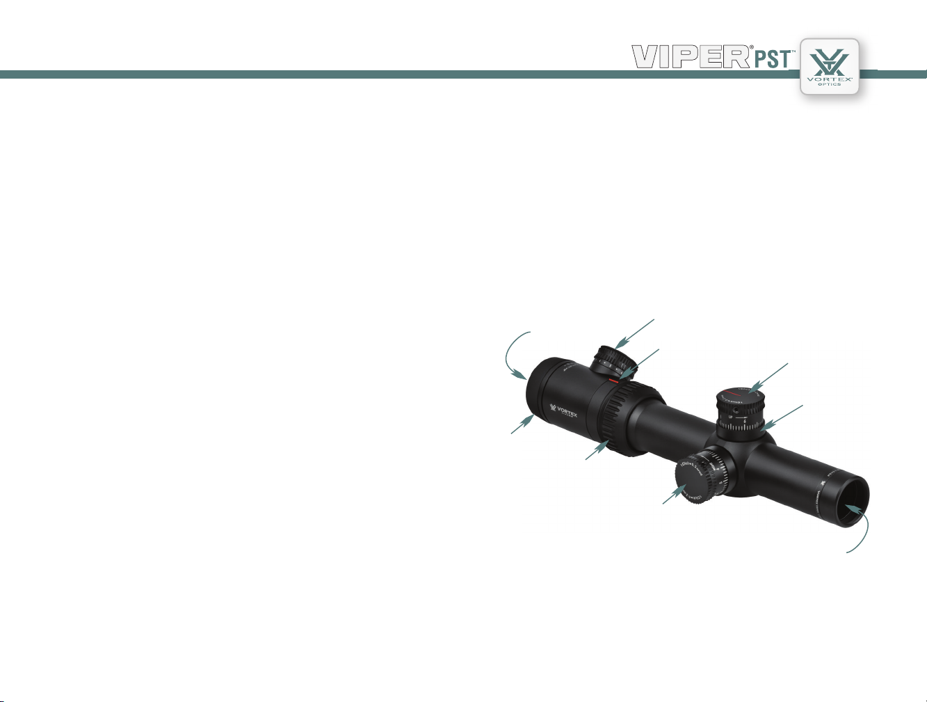
The VorTex® Viper® pSTTm 1-4x24 rifleScope
Specifically designed for the tactical, law enforcement and
committed precision shooting communities, the Viper®PST 1–4x24
riflescopes offer the highest levels of performance and reliability.
With features such as matched turret/reticle subtensions, CRS zero
stop mechanisms and precision ranging reticles, the Viper PSTs are
ready for any situation.
Fast Focus Eyepiece
Illumination
Ocular
Lens
Reticle Focus
Magnification
Adjustment Ring
Adjustment Knob
MagView Indicator
Elevation
Adjustment Knob
Turret Shroud
Dual Use: Shooting Tactical / Hunting
US Patent 7,937,879
Windage Adjustment
Knob
Objective
Lens
3 2
Page 3

Second Focal Plane Reticle
This PST riflescope model uses a second focal plane (SFP) reticle.
The advantage of a SFP reticle is that it always maintains the same
appearance. Shooters using reticle hashmarks should be aware that
the listed subtensions used for estimating range, holdover, and wind
drift correction are only accurate at the 4x magnification.
The Subtension Scale: MOA or MRAD
Depending on which version you have purchased, your Viper PST
1–4x24 riflescope will feature adjustments and reticles scaled in MOAs
or mrads. If you are unsure of which scale is used, reference the top of
the adjustment turret.
If the adjustment is in MOAs,
the turret will display
“1 Click = 1/2 MOA”.
Both minute-of-angle (MOA) and milliradian (mrad) unit of arc scales
are effective when ranging or adjusting riflescope for bullet trajectory.
If the adjustment is in mrads,
the turret will display
“1 click = .2 mrad”.
RIFLESCOPE
MOA Adjustments
MOA unit of arc measurements are based on degrees and minutes.
There are 360 degrees in a circle and 60 minutes in a degree for a total
of 21,600 minutes (MOA) in a circle. A minute of angle will subtend
1.05 inches at a distance of 100 yards. Viper PST 1–4x24 riflescopes
with MOA adjustments use 1/2-minute clicks which subtend .52 inches
at 100 yards, 1.05 inches at 200 yards, 1.57 inches at 300 yards, etc.
MRAD Adjustments
Mrad unit of arc measurements are based on the radian. A radian is the
angle subtended at the center of a circle by an arc that is equal in length
to the radius of the circle. There are 6.283 radians in all circles and
1000 milliradian in a radian for a total of 6283 milliradians (mrads) in a
circle. An mrad will subtend 3.6 inches at a distance of 100 yards. Viper
PST 1–4x24 riflescopes with mrad adjustments use .2 mrad clicks which
subtend .72 inches at 100 yards, .1.44 inches at 200 yards (4 cm at 200
meters), 2.16 inches at 300 yards (6 cm at 300 meters), etc.
5 4
Page 4
RIFLESCOPE
rifleScope AdjuSTmenTS
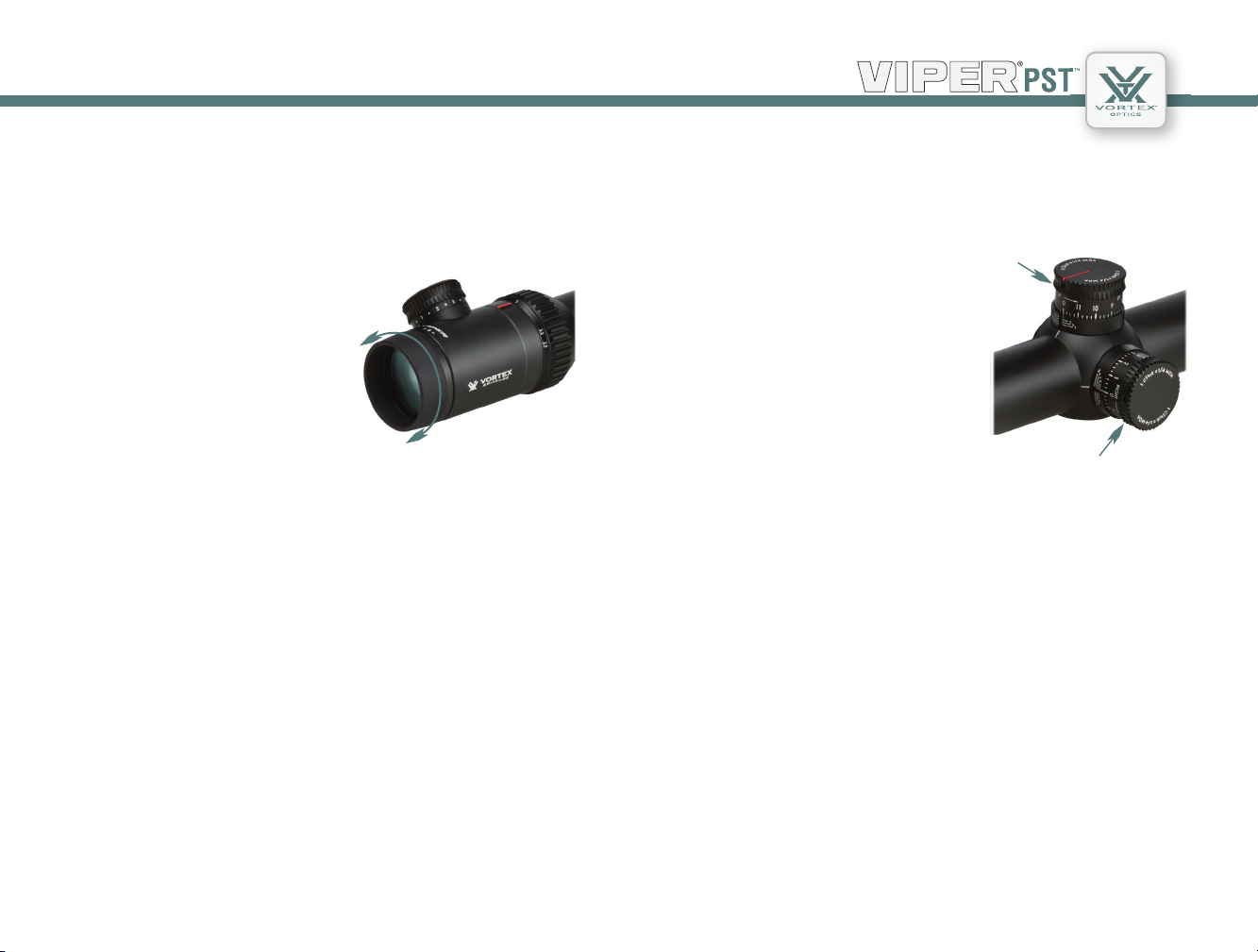
Reticle Focus
Vortex Viper PST riflescopes use a fast focus eyepiece designed to quickly
and easily adjust the focus on the riflescope’s reticle.
To adjust the reticle focus:
1. Look through the riflescope at a
blank white wall or up at the sky.
2. Turn the eyepiece focus knob in
or out until the reticle image is as
crisp as possible.
Adjust the reticle focus.
Note: Try to make this particular adjustment quickly, as the eye will try to
compensate for an out-of-focus reticle.
Once this adjustment is complete, it will not be necessary to re-focus
every time you use the riflescope. However, because your eyesight may
change over time, you should re-check this adjustment periodically.
Warning
Looking directly at the sun through a riflescope, or any optical instrument,
can cause severe and permanent damage to your eyesight.
About Parallax
Windage and Elevation Adjustments
Vortex Viper PST riflescopes incorporate precision finger adjustable elevation
and windage dials with audible clicks.
Elevation
To make adjustments:
1. Turn the adjustment knob in the
appropriate direction: Up/Down or
Left/Right as indicated by the arrows.
2. Following the directional arrows,
turn the knobs in the direction you wish
the bullet’s point-of-impact to go to.
MOA Adjustments
With each click of the Viper PST moving the point-of-impact 1/2 MOA,
it will take two clicks of the knob to move a bullet’s point-of-impact 1.05
inches at a 100 yard sight-in distance.
MRAD Adjustments
With each click of the Viper PST moving the point-of-impact .2 mrad
(.72 inches), two clicks will move the bullet’s point-of-impact 1.44 inches
at a 100 yard sight-in distance. At 100 meters, two clicks will move the
point-of-impact four centimeters.
Knob
Windage Knob
This Viper PST 1-4x24 riflescope does not have a parallax focus and is
factory focussed at a distance of 100 yards. Using good consistent shooting
form and cheek weld when shooting at distances other than 100 yards will
minimize most error problems associated with parallax.
7 6
Page 5

RIFLESCOPE
Variable Power Adjustments
To change magnifications, turn the magnification ring to the desired level.
The patented Vortex MagView
system will provide a low light
Magnification
Ring
MagView
reference for magnification level.
Illumination Adjustments
The Vortex Viper PST riflescopes
use a variable intensity reticle
illumination system to aid in low
light performance. To activate the
illumination, rotate the adjustment
knob in either direction.
The illumination knob allows for 10 levels of brightness intensity; an off
click between each level allows the shooter to turn the illumination off
and return to a favored intensity level with just one click.
Illumination
Knob
Replacing the Battery
1. Unscrew the outer cap with a coin.
2. Remove the battery.
3. Replace with a new CR2032 battery.
4. Re-install the outer battery cap and be sure to fully tighten it down.
Battery Cap
9 8
Page 6

RIFLESCOPE
Turret Rotation
Vortex Viper PST riflescopes incorporate Vortex’s patented Radius Bar
to visually assist in keeping track
of turret rotations. The radius
bar provides a quick visual
reference that allows the shooter
to confirm:
• Knob orientation is correct
Turret Cap
Retaining
Screw
and has not shifted as a result of
accidental contact.
• Knob orientation is at the
zero point when using the CRS
feature.
• By watching the position of
the bar while making elevation adjustments, the shooter is able to quickly
track full, half and quarter rotations.
To get these benefits from the Radius Bar, the “0” mark on the turret must
be indexed with the zero reference line on turret post (see Setting the
CRS Stop and Indexing Elevation Knob section on page 17).
Radius Bar
Zero Reference Lines
Customizable Rotational Stop (CRS)
Vortex Viper PST riflescope elevation turrets incorporate the unique
CRS rotation stop feature. After the rifle is sighted in, the design of the
CRS allows a shooter to quickly and easily return to an original zero
point when using the elevation turret to dial-in temporary bullet drop
corrections.
The CRS feature is particularly useful when dialing large multi-
revolution elevation corrections. Without this feature, the shooter
must pay very careful attention when dialing these large corrections.
If the shooter loses track of the number of revolutions, the original
zero point may become lost when returning the adjustment. Viper PST
riflescopes equipped with the CRS allow the elevation dial to be quickly
spun back to original zero without having to carefully count revolutions
or clicks.
Once the CRS shims are installed after sight-in, the elevation dial will
stop turning shortly past the original zero point when being returned
(turning clockwise direction) from a temporary elevation adjustment.
The shooter can then turn the elevation knob a partial turn in a
counter-clockwise direction until the zero reference and radius bar are
correctly aligned—achieving the original zero point.
See CRS shim installation in the
Bore Sighting and Final Range
Sight-in sections.
CRS Shims
11 10
Page 7

RIFLESCOPE
rifleScope mounTing
To get the best performance from your Vortex Viper PST riflescope,
proper mounting is
essential. Although not
difficult, the correct
steps must be followed.
If you are unsure of your
abilities, it would be best
to use the services of a
qualified gunsmith.
Centering of the Reticle
The Vortex Viper PST riflescope is pre-set from the factory with the reticle
in the center of the adjustment ranges.
If you have changed the settings and wish to approximately reset the reticle
to the center, this can be done easily:
1. Turn the windage or elevation dial as far as possible in either direction.
Do not force the dial. As soon as any resistance is felt, stop turning.
2. Carefully count the dial rotations while turning the dial back in the
opposite direction. Stop turning as soon as resistance is felt.
3. Turn the dial the other direction to half the amount of rotations
counted in step one.
Rings and Bases
Mount an appropriate base and matching rings to your rifle according
to the manufacturer’s instructions. The Vortex Viper PST riflescopes
require 30 mm rings.
Ring height for Viper PST 1–4x24 riflescopes will depend on the firearm
and mount being used. Consult the ring and base manufacturer for
suggested heights..
Use 30 mm rings.
AR-style rifles will usually require an extra-high mounting height on a
specialized cantilever-style mount such as the Vortex ADR-X cantilever
ring mount (shown above).
Complete this procedure for both windage and elevation dials to
approximately center the reticle.
13 12
Page 8

RIFLESCOPE
Eye Relief and Reticle Alignment
After installing the bottom ring halves on the mounting base, place the
riflescope on the bottom ring halves and loosely install the upper ring
halves. Before tightening the scope ring screws, adjust for maximum
eye relief to avoid injury from recoil:
1. Set the riflescope to the middle of its magnification range.
2. Slide the riflescope as far forward as possible in the rings.
3. While viewing through the riflescope in a normal shooting position,
slowly slide the riflescope back towards the shooter’s face—paying
attention to the field of view. Just as the full view is visible, stop.
4. Without disturbing the front-back placement, rotate the riflescope
until the vertical crosshair exactly matches the vertical axis of the rifle.
Use of a reticle leveling tool, a weight hung on a rope, flat feeler gauges,
or bubble levels will help with this procedure.
5. After aligning the reticle, tighten and torque the ring screws down
per the manufacturer’s instructions.
Bore Sighting
Initial bore sighting of the riflescope will save time and money at the
range. This can be done by using a mechanical or laser bore sighter
according to the manufacturer’s instructions or by removing the bolt
and sighting through the barrel on some rifles.
To visually bore sight a rifle:
1. Place the rifle solidly on a rest and remove the bolt.
2. Sight through the bore at a target approximately 100 yards away.
3. Move the rifle and rest until the target is visually centered inside the
barrel.
4. With the target centered in the bore, make windage and elevation
adjustments until the reticle crosshair is also centered over the target.
Using bubble levels
to square the
riflescope to the
base.
Visually bore-sighting a rifle.
15 14
Page 9

RIFLESCOPE
Final Range Sight-In and CRS Stop Set
After the riflescope has been bore-sighted, final sight-in and CRS
stop set should be done at the range using the exact ammunition
expected to be used while shooting. Sight in and zero the riflescope at
the preferred distance. 100 yards is the most common zero distance,
although a 200 yard zero may be preferred for long range applications.
Note: Be sure the reticle is in focus (see Reticle Focus section on page 6).
1. Following all safe shooting practices, fire a three-shot group as
precisely as possible.
2. Next, adjust the reticle to match the approximate center of the shot
group (see Windage and Elevation Adjustment section on page 7).
Note: If the rifle is very solidly mounted and cannot be moved, simply
look through the scope and adjust the reticle until it is centered on the
fired group.
3. Carefully fire another three-shot group and see if the bullet group is
centered on the bullseye.
This procedure can be repeated as many times as necessary to achieve a
perfect zero.
Setting the CRS Stop and Indexing Elevation Knob
After obtaining a satisfactory zero, the CRS stop can be set if desired:
1. Loosen the three turret cap retaining screws on the elevation turret.
Gently pull the turret cap straight up and off of the turret post, being
careful not to rotate the turret post.
2. Slide the CRS shims on the center section of the turret post below the
V-grooved part.
Place CRS shims
in this groove.
Alternate shim installation direction
with each shim.
Use as many shims as necessary to
completely fill up the space. Do not try to
force in a last shim once the clearance is
very close—a tiny remaining gap is normal.
17 16
Page 10

RIFLESCOPE
3. After filling the center gap on the post with shims, replace the elevation
cap.
4. Align the turret cap so the “0” mark on the cap matches up with
the “0” reference line on the turret shroud.
Again, be sure not to rotate the actual turret
mechanism in the process.
5. Re-tighten the retaining screws, but do not
overtighten. Use of thumb and forefinger on
the short end of the hex wrench will provide
Align the elevation turret cap.
sufficient force.
Indexing the Windage Knob
1. Loosen the three retaining screws on windage turret cap.
2. Carefully rotate the cap until the “0” mark on the cap matches up with
the “0” reference line on the turret post. Be sure that the cap is freely
turning and that you don’t rotate the actual turret mechanism.
3. Re-tighten the windage knob retaining screws, but do not overtighten.
Use of thumb and forefinger on the short end of the hex wrench will
provide sufficient force.
Once the windage and elevation knobs
are correctly indexed to the zero mark,
temporary corrections can be safely dialed
into the scope without worry of losing the
original zero.
Using the CRS Zero Stop
Once the CRS shims are installed, the elevation dial will stop turning
shortly past the original zero point when being returned (turning
clockwise direction) from a temporary elevation adjustment.
Turn the elevation knob a partial turn in a counter-clockwise direction
until the Radius Bar is
correctly aligned with scope
axis and zero marks match.
This setting will match the
original zero point.
Note: If re-zeroing at a
future time, be sure to
Point at which the knob stops turning.
remove all CRS shims
before sight-in.
Correct alignment for zero point.
Align the windage turret cap.
19 18
Page 11

RIFLESCOPE
mAinTenAnce
Cleaning
The fully waterproof and fogproof Vortex Viper PST riflescope requires
very little routine maintenance other than periodically cleaning the
exterior lenses. The exterior of the scope may be cleaned by wiping with a
soft, dry cloth.
When cleaning the lenses, be sure to use products, such as the Vortex Fog
Free cleaning products or Lens Pen, that are specifically designed for use
on coated optical lenses.
• Be sure to blow away any dust or grit on the lenses prior to wiping the
surfaces.
• Using your breath, or a very small amount of water or pure alcohol, can
help remove stubborn things like dried water spots.
Lubrication
All components of the Vortex Viper PST riflescopes are permanently
lubricated, so no additional lubricant should be applied.
Note: Other than to remove the turret caps, do not attempt to
disassemble any components of the riflescope. Disassembling of riflescope
may void warranty.
Storage
If possible, avoid exposing your Vortex riflescope to direct sunlight or any
very hot location for long periods of time.
TroubleShooTing
Sighting-in Problems
Many times, problems thought to be with the scope are actually
mount problems. Be sure the mounts are tight to the rifle and the
scope is secured so it doesn’t twist or move in the rings.
An insufficient windage or elevation adjustment range may indicate
problems with the base mount, base mount holes drilled in the rifle’s
receiver, or barrel/receiver alignment.
Check for Correct Base and Ring Alignment
1. Re-center the scope reticle (see Centering of the Reticle section
on page 12).
2. Attach bore sighter, or remove bolt and visually boresight rifle.
3. Look through the scope. If the reticle appears way off center on
the boresighter image or when compared to the visually centered
target when looking through rifle’s bore, there may be a problem with
the bases or rings being used. Confirm that correct base and rings are
being used—and in the proper orientation.
Grouping Problems
There are many issues that can cause poor bullet grouping.
• Maintain a good shooting technique and use a solid rest.
• Check that all screws on rifle’s action are properly tightened.
• Be sure rifle barrel and action are clean and free of excessive
oil or copper fouling.
• Check that rings are correctly torqued per the manufacturer’s instructions.
• Some rifles and ammunition don’t work well together—try different
ammunition and see if accuracy improves.
21 20
Page 12

The Vip WArrAnTy
We build optics based on our commitment to your absolute satisfaction.
That’s why Vortex products are unconditionally guaranteed and we make
this Very Important Promise to you—a Very Important Person.
Rest assured that in the event your Viper PST becomes damaged or
defective, Vortex Optics will repair or replace
the riflescope at no charge to you. Call
Vortex Optics at 800-426-0048 for prompt,
professional, and friendly service.
Vortex Optics
2120 West Greenview Drive
Middleton, WI 53562
service@vortexoptics.com
Visit www.vortexoptics.com for more information. Canadian customers
may visit www.vortexcanada.net for customer service information.
Note: The VIP warranty does not cover theft, loss, or deliberate damage
to the product.
Unlimited
Unconditional
Lifetime Warranty
RIFLESCOPE
23 22
Page 13

 Loading...