


LR


 HS LR
HS LR
RIFLESCOPE
rIFLESCOPE mANUAL
Second Focal Plane Reticle


 HS LR
HS LR
RIFLESCOPE
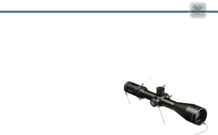
The Vortex® Viper® HS LR™ Riflescopes
The Vortex®Viper®HS LR™ riflescopes are intended for dedicated long range hunters. Using a specially designed uncapped, rapid travel elevation turret with our CRS zero stop, this riflescope accommodates the unique needs of hunters who prefer to “dial in” elevation adjustments for long range shots.
The Viper HS LR series riflescopes also provide an ideal platform for the optional Vortex TMT custom turret caps. Visit our website, www.vortexoptics.com, for more information on the TMT caps.
Fast Focus |
|
|
Eyepiece |
MagView |
Elevation |
|
|
Adjustment Knob |
|
|
Side Focus Knob |
Reticle Focus
Magnification
Adjustment Ring
Windage |
|
Adjustment Knob |
Objective |
|
|
|
Lens |
Dual Use: Shooting Tactical / Hunting
US Patent 7,937,879
2 |
3 |
RETICLE OPTIONS
The Focal Plane
All riflescope reticles can be termed either first focal plane (FFP) or second focal plane (SFP), depending upon their internal location within the riflescope. This model features the second focal plane design.
SECOND FOCAL PLANE RETICLES
Second focal plane (SFP) reticles are located near the scope’s eyepiece behind the image erecting and magnifying lenses. This style of reticle does not visually change in size when you change the magnification. The advantage of an SFP reticle is that it always maintains the same appearance. Listed reticle subtensions used for estimating range, holdover, and wind drift correction are only accurate at one particular magnification.


 HS LR
HS LR
RIFLESCOPE
RIFLESCOPE ADJUSTMENTS
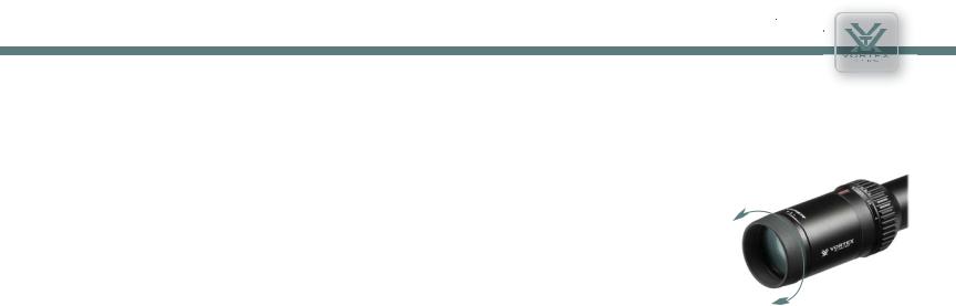
Reticle Focus
The Viper HS LR riflescope uses a fast focus eyepiece designed to quickly and easily adjust the focus on the riflescope’s reticle.
To adjust the reticle focus:
1. Look through the riflescope at a blank white wall or up at the sky.
2. Turn the eyepiece focus knob in or out until the reticle image
is as crisp as possible. |
Adjust the reticle focus |
|
Note: Try to make this particular adjustment quickly, as the eye will try to compensate for an out-of-focus reticle.
Once this adjustment is complete, it will not be necessary to re-focus every time you use the riflescope. However, because your eyesight may change over time, you should re-check this adjustment periodically.
Warning
Looking directly at the sun through a riflescope, or any optical instrument, can cause severe and permanent damage to your eyesight.
4 |
5 |
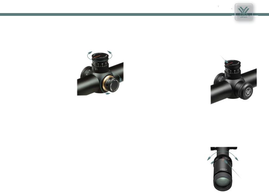
Windage and Elevation Adjustments
The Vortex Viper HS LR riflescope incorporates precision finger adjustable elevation and windage dials with audible clicks.
To make adjustments: |
Elevation Knob |
|
|
1. Turn the adjustment knob in the |
|
appropriate direction: Up/Down or |
|
Left/Right as indicated by the arrows. |
|
2. Following the directional arrows, turn |
|
the knobs in the direction you wish the |
|
bullet’s point-of-impact to go to. |
|
Note: After sight-in, you can re-align the zero marks on the turret knobs with the
reference dots if you wish (see Indexing Adjustment Dials with Zero Reset on page 15). Replace outer covers when done.
MOA ADJUSTMENTS
The Viper HS LR riflescopes use finger adjustable elevation and windage turrets with scales measured in minutes of angle (MOA). MOAs are
a unit of arc measurement which equals 1.05 inch for each 100 yards. Examples: 2.1 inches @ 200 yards, 3.15 inches @ 300 yards, etc.
The tactical-style elevation turret is designed to provide a high travel range along with rapid adjustment ability. Each click will provide ½ MOA of reticle movement (approximately ½-inch @ 100 yards).
The windage turret uses a standard design with an external cap. Each click will provide ¼ MOA of reticle movement (approximately ¼-inch @ 100 yards).


 HS LR
HS LR
RIFLESCOPE
Turret Rotation
Vortex Viper HS LR riflescopes incorporate Vortex’s patented Radius Bar to visually assist in keeping track of turret rotations. The Radius Bar provides a quick visual reference that allows the shooter to confirm:
• Knob orientation is correct and has |
Radius Bar |
not shifted as a result of accidental |
|
contact. |
|
•Knob orientation is at the zero point when using the CRS feature.
•By watching the position of the bar while making elevation adjustments, the shooter is able to quickly track full, half and quarter rotations.
To get these benefits from the Radius Bar, the “0” mark on the turret must be indexed with the zero reference line on turret post (see Setting the CRS Stop and Indexing Elevation Knob on page 14).
Variable Power Adjustments
To change the magnification, turn the magnification ring to the desired level. The Vortex fiber optic
magnification indicator will provide a low light reference for magnification level.
Magnification
Scale
MagView
Indicator
6 |
7 |
 Loading...