

Page 1
OWNER’S MANUAL
for
VORTEX RECON SCOPE
The Vortex Versatile Mount System
The patented Vortex VMS kit is designed to provide the user
with a highly flexible,
adaptive system to
stabilize the Vortex
Recon scope along
with any Picatinny rail
mounted accessories.
Due to its modular
design, the VMS
offers many options
in mounting rail
locations for these
accessories.
The key advantage to the VMS kit is its ability to fit virtually
any application and use with the Recon scope. There is no
right or wrong way to assemble the VMS—each use may be
slightly different, and the VMS is designed to be as versatile as
possible.
1
Page 2
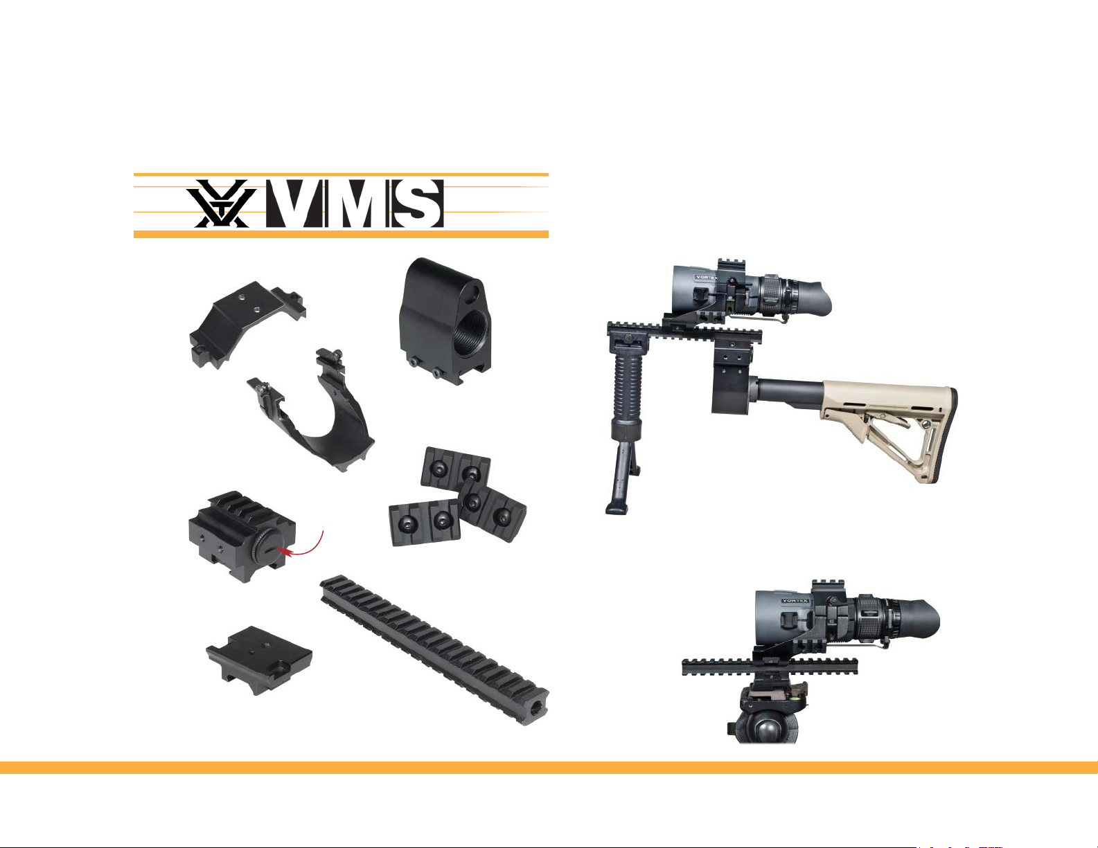
Included Accessories
Lower U-Bracket
Recon R/T VMS with Shoulder Stock and Bipod.
Upper U-Bracket
AR15 Stock Adapter
Bipod and shoulder stock not included.
Battery
Compartment
Picatinny Rail Spacer
Picatinny Rail
Tripod Adapter Mount
(3) Short Picatinny Rails
Long Double Picatinny Rail
23
Recon R/T with VMS on Tripod.
Tripod not included.
Page 3
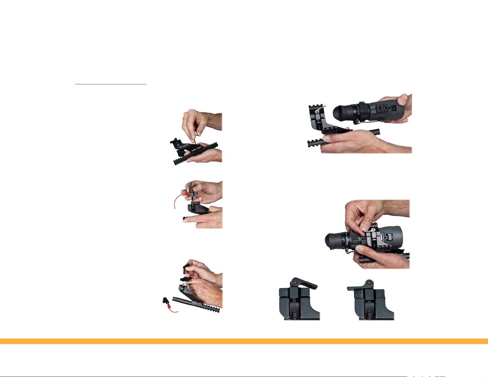
Setting Up the VMS Kit
U-bracket
Install the VMS lower U-bracket onto the long Picatinny rail,
positioning as desired. To attach,
loosen the mounting screw and engage
the clamp on desired rail slot. Be
sure the clamp and crossbolt are fully
engaged and retighten screw.
If desired, upper U-bracket may be installed on top of lower
U-bracket. Upper U-bracket is only
necessary for top-mounted accessories.
To install, unscrew flip levers from
lower U-bracket (turn counter-
Bracket Cl amp
clockwise) until they can be
removed. Be careful to leave small
springs in place when removing screws.
Remove the bracket clamps from flip lever screws
(bracket clamps will not be used
with upper U-bracket).
Install flip lever screws through
holes in upper U-brackets. Install
screws through springs and down
into threads on lower U-bracket.
Bracket
Clamp
Tighten screws until finger tight,
and then back off approximately two turns.
Release the flip levers on the lower VMS U-bracket and slide
the Recon into
bracket. The
Recon can be
positioned in
U-bracket in
either direction.
Be sure the rail
segments and
Slide Recon R/T into bracket.
grooves are engaged and flip levers down to locked position,
clamping the Recon in place. To adjust clamping pressure, the
flip levers can be turned in or out.
Flip levers to locked position.
Lever in released position. Lever in locked position.
45
Page 4

Accessory Picatinny Rails
If desired, short accessory Picatinny rails may be installed
on sides and top of U brackets. Rails may also be installed
on sides of AR stock spacer using included screws.
Installing rail on top of
U-bracket.
Attaching Accessories
Generally, most users will want to stabilize the VMS kit
using popular aftermarket accessories such as vertical
AR15 style bipod grips, tripods or AR15 type riflestocks.
These may be used individually or in any combination
desired.
Tripod Adapter Plate
To use a tripod, the tripod
adapter plate must be
installed on bottom of
long rail. Adapter plate
will accept standard
tripod mounting screw.
Installing rail on side
of U-bracket.
Recon R/T with VMS shown installed
on a quick-release style tripod.
67
Page 5

AR15 Stock Adapter
To use an AR15 stock, the stock adapter must be installed on
bottom rear of long rail.
If desired, the AR spacer
can be used between
rail and stock adapter
for a lower stock height
and additional mounting
locations for Picatinny
rails. AR spacer includes
Stock Adap ter
AR Spacer
small battery compartment.
Other Accessories
Accessories using Picatinny rail clamps may be located in
several locations on the VMS
kit U-brackets depending on
user preference.
Vertical grip installed on
bottom part of the long rail.
Thread the AR stock into
AR stock adapter.
AR stock not included.
Attach rail spacer to bottom of long
Picatinny rail and AR stock adapter
to bottom of rail spacer.
Laser rangefinder installed on
top of the U-bracket.
Flashlight installed on left
side of the U-bracket.
Shown accessories, the vertical bipod grip,
tripod, and AR stock are not included.
89
Page 6

Other Accessories
In-line optics enhancers such as
thermal devices and NV can be
mounted forward of Recon R/T on
the long rail.
Recon R/T on VMS with Multiple Accessories Installed
Laser designator installed on right
side of the U-bracket.
Shown accesories not included.
Shown accesories not included.
10 11
Page 7

Vortex Service and Repair Policy
Vortex Lifetime Limited Warranty
Vortex Optics offers a lifetime
limited warranty against
manufacturer defects in materials
and workmanship for the life of the
product. Rest assured, if the VMS
should ever require repair, all you
need to do is contact Vortex for
service.
Call 800-426-0048 or e-mail
service@vortexoptics.com.
Vor tex Optics
2120 West Greenview Drive
Middleton, Wisconsin 53562
USA
12 13
 Loading...