

Page 1
5-20x50 Riflescope
Page 2
At Vortex Optics, the need for high-performance,
precision optics is the driving force behind all that
we do.
That’s why we carefully built the Razor HD riflescope
®
to provide shooters with the ultimate long range tactical
riflescope. Built on an incredibly tough one piece 35mm
main tube and using a state-of-the-art optical system
and erector mechanism, the Razor 5–20x50 delivers
superior accuracy and rugged reliability under the
harshest conditions.
Specifications . . . . . . . . . . . . . . . . . . 2
Adjustments . . . . . . . . . . . . . . . . . . . 4
Mounting . . . . . . . . . . . . . . . . . . . . . 10
Maintenance . . . . . . . . . . . . . . . . . . 18
Troubleshooting . . . . . . . . . . . . . . . . 19
Vortex Service and Repair Policy . . . . . . 20
1
Page 3
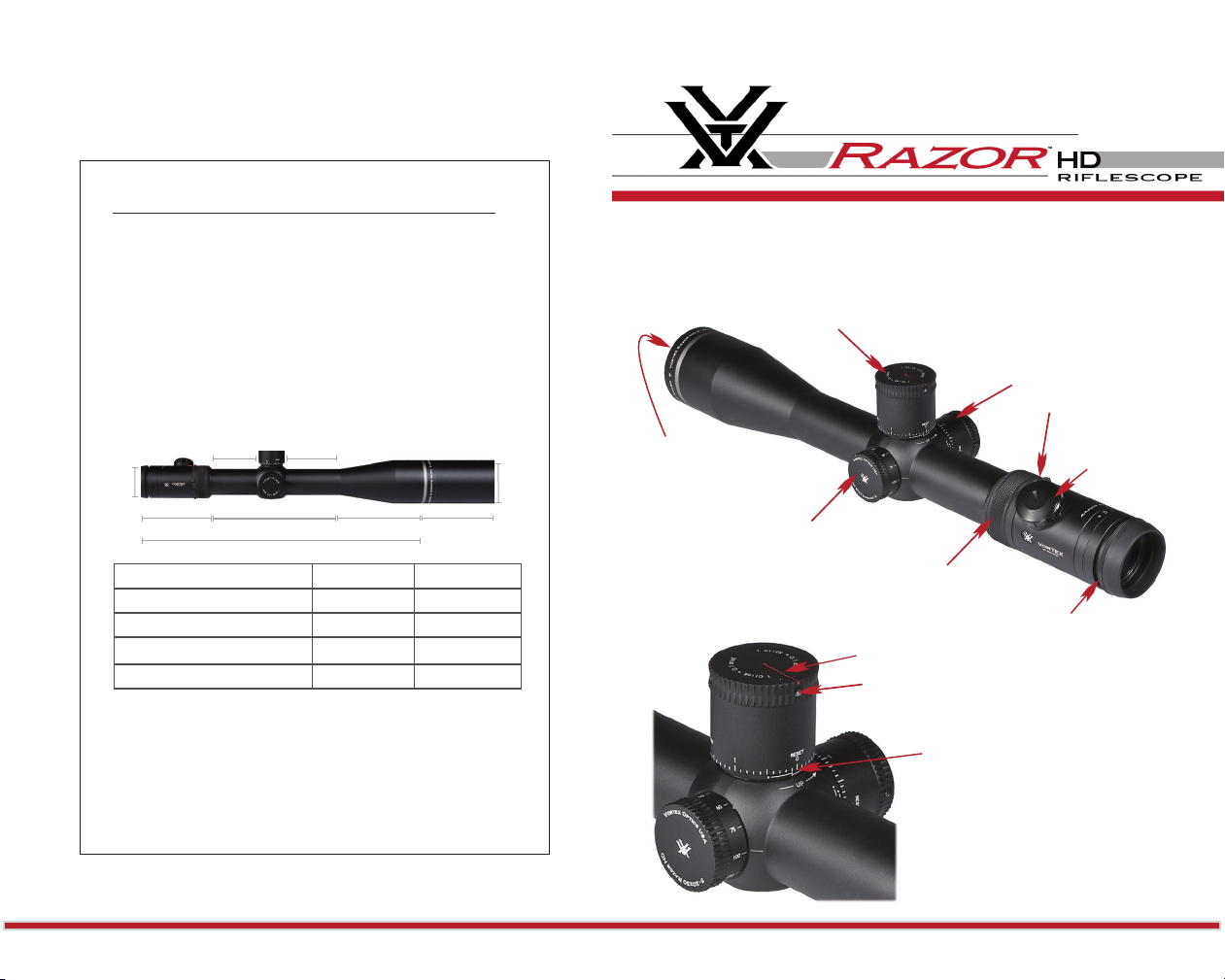
Razor 5–20x50 Riflescope Specifications
Waterproof Yes
Fogproof Argon gas purging
Lengt h 15.8 inch es (402 mm)
Mounti ng Length 6.9 inch es (175 mm)
Weight 35.2 ou nces (1000 g)
Eye Reli ef 3.9 inch es (100 mm)
Field of V iew 5x: 22.0 f eet /100 yar ds (4.2°)
20x: 5. 76 feet /100 ya rds (1.1°)
Recoil Te sted Rated for . 50 BMG
Battery CR2032
The Vortex Razor HD 5-20x50 Riflescope
RZR Zero Stop and Elevation
Adjustment Knob
Windage
Adjustment Knob
MagVie w
(Eyepiec e) (Sunshade)
1.74”
(43mm)
4.0” (102mm)
2.5”
(64mm)
6.9” ( 175mm)
15.8” (402mm)
2.9”
(74mm)
4.9” (125m m) 4.0” (102mm)
Razor HD Models MOA MRAD
Adjustment Graduation 1/4 MOA .1 MR AD
Elevation Adjustment 12 5 MOA 36 MR AD
Windage Adjustment 125 MOA 36 MR AD
Travel Per Rotation 15 or 25 MOA 5 o r 10 MRAD
2 3
4
2.33”
(58mm)
Objective Lens
Illumination Knob
and Bat tery Cover
Side Parallax Focus
Magnification
Adjustment Ring
Reticl e Focus
Radius Bar
(3) Turret C ap
Retaining Screws
Zero Reference
Line
5
Page 4
Riflescope Adjustments
Windage and Elevation Adjustments
MOA Adjustments
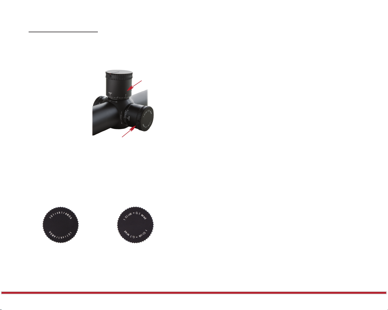
Vortex 5–20x50 Razor riflescopes incorporate precision
finger adjustable elevation and windage knobs with audible
and tactile clicks.
To make adjustments:
Elevation
Adjustment Knob
1. Turn the adjustment
knob in the appropriate
direction: Up/Down or
Left/Right as indicated by
the arrows.
2. Move the knobs in the
direction you wish the
Windage
Adjustment Knob
bullet’s point-of-impact to
change.
Depending on which version you have purchased, your Razor
5–20x50 riflescope will feature adjustments scaled in MOAs
or mrads. If you are unsure of which scale is used, reference
the top of the adjustment turret.
If the adjustment is in MOAs,
the turret will display
“1 Click = ¼ MOA”.
If the adjustment is in mrads,
the turret will display
“1 click = 1/10 mrad”.
Most shooters are familiar with the minute–of-angle (MOA)
system commonly used in hunting riflescopes. MOA
measurements are based on degrees and minutes: 360 degrees
in a circle, 60 minutes in a degree, for a total of 21,600. When
comparing MOAs and mrads, 3.44 MOAs are equal to 1
mrad. These angular measurements are used for ranging and
correcting for the bullet’s trajectory drop in riflescopes.
Each click will move the point-of-impact 1/4 MOA. 1/4 MOA
closely corresponds to .26 inches at 100 yards, .52 inches at
200 yards, .78 inches at 300 yards, etc.
Example: At a 100 yard sight-in distance, it will take four clicks
of the knob to move a bullet’s point-of-impact 1.05 inches.
MRAD Adjustments
The milliradian (mrad for short) is a form of angular
measurement similar in concept to a degree although much
finer. A degree is 1/360 of a circle; a milliradian is 1/6283 of
a circle.
Each click will move the point-of-impact 1/10 mrad. 1/10
mrad equals .36 inches at 100 yards (1 cm at 100 meters),
.72 inches at 200 yards (2 cm at 200 meters), 1.08 inches at
300 yards (3 cm at 300 meters), etc.
Example: At a 100 yard sight-in distance, four clicks will move
the bullet’s point-of-impact 1.44 inches. At 100 meters, four
clicks will move the point-of-impact four centimeters.
4 5
6
7
Page 5

Reticle Focusing
Parallax Adjustment
Vortex Razor riflescopes use a fast focus eyepiece designed
to quickly and easily adjust the focus on the riflescope’s
reticle.
Try to make this particular
adjustment quickly, as the
eye will try to compensate
for an out-of-focus reticle.
Adjust the reticle focus
To adjust the reticle focus:
1. Look through the riflescope at a blank white wall or up
at the sky.
2. Turn the eyepiece focus knob in or out until the reticle
image is as crisp as possible.
Note: Once this adjustment is complete, it will not be
necessary to re-focus every time you use the riflescope.
However, because your eyesight may change over time,
you should re-check this adjustment periodically.
The Razor HD 5–20x50 riflescope uses a side focus parallax
adjustment which, when properly set, eliminates parallax
errors. Properly setting a side focus parallax adjustment is a
quick procedure. When properly set, the target image should
be sharp and crisp.
To set the parallax:
1. First, be sure the reticle is correctly focused (see Reticle Focusing).
2. As accurately as possible, match the yardage number (distance you
are shooting) on side focus parallax adjustment knob to the indicator
arrow on the scope body.
3. Check the setting for accuracy
by moving your head back and
forth while looking through the
scope. The setting is correct if
there is no apparent movement
between the reticle and target. If
there is apparent movement, adjust
the focus knob slightly until the
Adjust t he side paral lax knob
movement is eliminated.
Parallax is a phenomenon that results when the target image does not
quite fall on the same optical plane as the reticle within the scope.
When the shooter’s eye is not precisely centered in the eyepiece, there
can be apparent movement of the target in relation to the reticle,
which can cause a small shift in the point of aim. Parallax error is most
problematic for precision shooters using high magnification.
6 7
8
9
Page 6

Turret Rotation
Vortex Razor riflescopes incorporate the Radius Bar to
visually assist in keeping track of
Radius Bar
turret rotations. By watching the
position of the bar while making
elevation adjustments, the shooter
is able to quickly track full, half
and quarter rotations. To get the
most benefit from the Radius Bar,
the “0” mark on the turret must be
indexed with the zero reference line on turret post.
Illumination Adjustments
The Vortex Razor HD 5–20 x 50 riflescope uses a variable
intensity reticle illumination system to aid in low light
performance. To activate the illumination, rotate the
adjustment knob in a clockwise direction. The illumination
knob allows for 11 levels of brightness intensity; an off click
between each level allows the shooter to turn the illumination
off and return to a favored intensity level with just one click.
The top setting (11) is visible in the daytime, depending on
the background color. Settings below 11 are for low light use
when the user’s eyes have adjusted to lower light levels. Lowest
settings are for use with night vision devices.
To change batteries:
Battery Cap
1. Unscrew the outer cap with a coin.
2. Remove the CR2032 battery.
Variable Power Adjustments
MagView
To change magnifications, turn the
magnification ring to the desired
level. The Vortex MagView system
will provide a low light reference
for magnification level.
RZR Zero Stop Adjustment
Vortex Razor 5–20x50 riflescopes incorporate
the RZR Zero Stop feature. After the
rifle is sighted in, the RZR Zero Stop
allows fast, easy return to the original
zero point when large multi-revolution
elevation corrections have been dialed
into the riflescope.
Without a zero stop, the shooter must pay very careful
attention when dialing large corrections needing multiple
revolutions of the elevation knob. If the shooter loses track of
the number of revolutions, the original zero point may become
lost. Because of the RZR Zero Stop, the elevation knob on
Vortex Razor scopes can be quickly spun back to the original
zero without having to carefully count revolutions. Once the
RZR Zero Stop is set, the elevation knob will stop turning at
the original zero point when being returned from a temporary
elevation correction. Learn how to adjust the RZR Zero Stop
in the Bore Sighting and Range Sight-in sections.
3. Replace with a new CR2032 battery.
8 9
10
11
Page 7

Riflescope Mounting
To get the best performance from your Vortex Razor
riflescope, proper mounting
is essential. Although not
difficult, the correct steps
must be followed. If you
are unsure of your abilities,
it would be best to use
the services of a qualified
gunsmith.
Centering of the Reticle
The Vortex Razor HD riflescope is pre-set from the factory
with the reticle in the center of the adjustment ranges. This is
the best position to begin sight-in.
If you have changed the settings and wish to reset the
reticle to the center, this can be done easily:
1. Loosen the elevation turret cap retaining screws and remove
the elevation cap.
2. Loosen the eleveation zero stop lock screws.
3. Turn the windage and elevation turrets clockwise until
stopped.
Rings and Bases
Mount an appropriate base and matching rings to your
rifle according to the
manufacturer’s instructions.
The Vortex Razor 5–20x50
riflescope requires 35mm
rings.
Vortex Optics highly
recommends using the
matched Vortex Optics
Omega 35mm precision ring
sets which may be purchased
Use 35m m rings for the R azor 5–20 x50
from an authorized Vortex
riflescope dealer. These rings will mount to any quality Weaver
or Picatinny type base.
If using aftermarket rings, use the lowest ring height that will
give complete clearance of scope and rifle—avoiding any
contact with barrel, receiver, bolt handle or any other part of
the rifle. A low mounting will help assure proper cheek weld,
aid in establishing a solid shooting position, and promote fast
target acquisition.
4. Turn windage and elevation turrets counter-clockwise 4.25
full rotations to approximately center the reticle.
At this point, the riflescope is ready for bore sighting (see
Bore Sighting section).
10 11
12
13
Page 8

Eye Relief and Reticle Alignment
Bubble Level
Place the riflescope on bottom ring halves and loosely install
the upper ring halves. Before tightening the scope ring
screws, adjust for maximum eye relief to avoid injury from
recoil:
1. Set the riflescope to the middle of its magnification range.
2. Slide the riflescope as far forward as possible in the rings.
While viewing through the riflescope in a normal shooting
position, slowly slide the riflescope back towards the shooter’s
face—paying attention to the field of view. Just as the full view
becomes visible, stop.
3. Without disturbing the front-back placement, rotate the
riflescope until the vertical crosshair exactly matches the
vertical axis of the rifle. Use a reticle leveling tool, hanging
weight on a rope (see next page), or an adjustable set of feeler
gauges for this procedure.
4. After aligning the reticle, tighten and torque the ring screws
down per the manufacturer’s instructions.
Example of Squaring the Riflescope
Use of an adjustable set
of feeler gauges between
a one-piece base and
flat bottom section of the
riflescope to square the
riflescope (and reticle) to
the base.
After the riflescope is in the rings and the reticle matches
the vertical axis of
the rifle, the bubble
level may be mounted
Vertical Reference
to the riflescope
tube. Attach the level
to a location on the
scope tube that allows
Bubble Level
good visibility while
in shooting position
and does not block
view of parallax or
windage knobs. Most
shooters will prefer
mounting the level on
the forward section of
the riflescope tube.
Confirm the vertical orientation of the reticle.
1. Confirm the vertical orientation of the reticle by hanging
a weight from a heavy cord at a distance out in front of the
riflescope.
2. Visually level the bubble between lines and tighten screws
using thumb and forefinger on short end of hex wrench.
14
12 13
15
Page 9

Bore Sighting and RZR Zero Stop Preparation
Initial bore sighting of the riflescope will save time and money
at the range. This can be done by removing the bolt and
sighting through the barrel on a bolt action rifle, or using a
mechanical or laser bore sighter.
Preparing the RZR Zero Stop for setting:
1. Begin by turning the elevation knob clockwise until it stops.
2. Loosen, but do not remove, the three elevation turret cap
retaining screws.
3. Lift the elevation turret cap up and off the turret. This will
reveal the scale markings to be used for sight in.
4. Next, loosen, but do not remove, the three elevation zero
stop lock screws.
Loosen Elevation
Cap Scr ews
Remove
Elevation
Turret Cap
Loosen Zero Stop
Lock Screws
Note: You will not feel “clicks” as the
elevation knob is adjusted—this is
Sight-in
Adjustment
Scale
normal. The “clicks” will return after
final zero stop is set at the rifle range.
Use the graphic number scale to track
adjustments.
Bore sighting a bolt action rifle without a
mechanical or laser bore sighter:
1. Place the rifle solidly on a rest and remove the bolt.
2. Sight through the bore at a target approximately 100 yards away.
3. Move the rifle and rest until the target is visually centered inside
the barrel.
4. With the target centered in the bore, make elevation and
windage adjustments until the reticle crosshair is also centered
over the target.
Note: No initial adjustments are needed on the windage knob.
If using a mechanical or laser bore sighter, set up according
to manufacturer instructions. Make windage and elevation
adjustments until the reticle crosshair is aligned with the
adjustment pattern or laser dot.
16
14 15
Important
Do not re-tighten elevation zero stop lock screws or replace the turret
cap at this time; these will be tightened after the final sight-in.
17
Page 10

Range Sight-In and RZR Zero Stop Set
After obtaining satisfactory zero, set the RZR zero stop:
After the riflescope has been bore-sighted, final sight-in
and RZR Zero Stop set should be done at the range using
the exact ammunition expected to be used while shooting.
Sight in and zero the riflescope at the preferred distance.
100 yards is the most common zero distance, although a 200
yard zero may be preferred for long distance applications.
1. Be sure to follow all safe shooting practises. Before shooting,
be sure the reticle is in focus (see
Reticle Focus Adjustment).
2. At your preferred zero distance, fire a three-shot group as
precisely as possible.
3. Next, adjust the reticle to match the approximate center of the
shot group (see section on Windage and Elevation Adjustment).
As previously noted in the section on bore sighting, the elevation turret cap
turret should be removed and zero stop lock screws should be loosened.
4. If the rifle is very solidly mounted and cannot be moved,
simply look through the scope and adjust the reticle until it is
centered on the fired group.
5. Carefully fire another three-shot group and see if the bullet
group is centered on the bullseye.
If necessary, make another adjustment to the riflescope and
fire another group to verify zero. This procedure can be
repeated as many times as necessary to achieve a perfect zero.
1. Re-tighten the three zero stop lock screws. Do not over tighten:
thumb and forefinger on the short end of supplied hex wrench
will be sufficient.
2. Replace elevation turret cap, being sure to align “0” mark on cap
with the zero reference line on scope body. Push the cap straight
down and avoid turning while doing this.
3. Be sure the cap is fully down and re-tighten elevation cap
retaining screws. Do not overtighten: using thumb and forefinger
on short end of hex wrench will be sufficient.
Note: To re-zero for a different load, repeat complete bore
sighting and range sight-in procedures. It is important to always
begin any sight-in adjustments by turning elevation turret
clockwise until fully stopped.
Re-Indexing Zero Mark on Windage Knob
If desired, the windage knob may be re-indexed to zero after
sight-in. This will allow an easy return to the zero point if
temporary windage corrections are dialed in the field.
1. After completing the final sight-in, fully loosen the three
windage turret cap retaining screws and carefully pull the turret
cap straight off. Re-position with the “0” mark on the cap aligned
with the zero reference line on the turret post and push the cap
straight down. Avoid rotating while pushing down.
2. Be sure the cap is fully down and re-tighten windage knob
retaining screws. Do not overtighten: using thumb and forefinger
on short end of hex wrench will be sufficient.
16 17
18
19
Page 11

Maintenance
Troubleshooting
Cleaning
The Vortex Razor riflescope requires very little
routine maintenance other than periodically cleaning
the exterior lenses. The exterior of the scope may be
cleaned by wiping with a soft, dry cloth.
When cleaning the lenses, be sure to use products that are
specifically designed for use on coated optical lenses.
• Be sure to blow away any dust or grit on the lenses
prior to wiping the surfaces.
• Using your breath, or a very small amount of water or
pure alcohol, can help remove stubborn things like dried
water spots.
Lubrication
All components of the Vortex Razor HD are permanently
lubricated, so no additional lubricant should be applied. If
possible, avoid exposing your Vortex riflescope to direct
sunlight or any very hot location for long periods of time.
Note: Other than to remove the turret caps, do not attempt to
disassemble any components of the riflescope. Disassembling
of riflescope may void warranty.
Please check the following items prior to returning a
rif lescope for service.
Many times, problems thought to be with the scope are
actually mount problems. Verify use of correct base and
rings for the rifle and that these are correctly oriented and
tightened. The scope should not twist or move in the rings.
Insufficient windage or elevation adjustment range can indicate
an incorrect base, alignment problems with mount holes
drilled in base or rifle’s receiver, or alignment problems with
barrel and receiver.
If the rifle is failing to group well, there are several things to
easily check:
• Be sure the rifle’s action is bedded correctly, and all
mounting screws are properly tightened.
• The rifle’s barrel and action should be clean and free
of excessive oil or copper fouling.
• Also, some rifle/ammunition combinations simply
don’t work well together—try shooting different
ammunition and see if accuracy improves.
• Over torquing rings.
18 19
20
21
Page 12
The VIP Warranty
We build optics based on our commitment to your absolute
satisfaction. That’s why Vortex products are unconditionally
guaranteed and we make this Very Important Promise to you—a
Very Important Person.
Rest assured that in the event your
Razor HD riflescope becomes
damaged or defective, Vortex Optics
will repair or replace the riflescope
at no charge to you. Call Vortex
Optics at 800-426-0048 or e-mail
Unconditional Lifetime Warranty
service@vortexoptics.com for prompt,
professional, and friendly service.
Vor tex Optics
2120 West Greenview Drive
Middleton, Wisconsin 53562 USA
Visit vortexoptics.com for more information. Canadian customers
may visit vortexcanada.net for customer service information.
Note: The VIP warranty does not cover theft, loss, or deliberate
damage to the product.
US Patent 7,937,879 US Patent 7,958,665
Dual Use: Shooting Tactical / Hunting
20
Page 13

RZR-52000-13A
© Vortex Opt ics usa
 Loading...