

Volvo FM 2 Series, NH12 Series, FH 2 Series Service Manual
Service Manual
www.cargeek.ir
www.cargeek.ir
Trucks
Group 37
Release 01
D
Wiring diagram
FM, FH, VERSION2
CHID A652195–
CHID B486535–
CHID E735697–
CHID CKD875563–
20177893

Foreword
www.cargeek.ir
www.cargeek.ir
The descriptions and service procedures contained in this manual are based on designs
and methods studies carried out up to September 07.
The products are under continuous development. Vehicles and components produced
after the above date may therefore have different specifications and repair methods.
When this is judged to have a significant bearing on this manual, supplementary service
bulletins will be issued to cover the changes.
D
The new edition of this manual will update the changes.
In service procedures where the title incorporates an operation number, this is a
reference to V.S.T. (Volvo Standard Times).
Service procedures which do not include an operation number in the title are for general
information and no reference is made to V.S.T.
The following levels of observations, cautions and warnings are used in this Service
Documentation:
Note: Indicates a procedure, practice, or condition that mustbe followed in order to have
the vehicle or component function in the manner intended.
Caution: Indicates an unsafe practice where damage to the product could occur.
Warning: Indicates an unsafe practice where personal injury or severe damage to the
product could occur.
Danger: Indicates an unsafe practice where serious personal injury or death couldoccur.
Volvo Truck Corporation
Göteborg, Sweden
Order number: 20177893
© 07 Volvo Truck Corporation, Göteborg, Sweden
All rights reserved. No part of this publication may be reproduced, stored in
retrieval system, or transmitted in any forms by any means, electronic,
mechanical, photocopying, recording or otherwise, without the prior written
permission of Volvo Truck Corporation.
ENG23681.ihval

Contents
www.cargeek.ir
www.cargeek.ir
Example of wiring diagram ................................................................... 2
Component wiring diagram index ........................................................ 5
Component wiring diagrams ................................................................ 8
Illustrations index .............................................................................. 111
Illustrations ......................................................................................... 112
D
Fuses ................................................................................................... 209
Relays ................................................................................................. 211
Wiring harness illustration index ..................................................... 213
Ground connections .......................................................................... 216
List of ground connections ................................................................. 218
List of connectors .............................................................................. 219
List of components ............................................................................ 229
Abbreviations ..................................................................................... 235
Cable colour code .............................................................................. 237
Feedback
1
Group 37 Wiring diagram FM, FH, NH12 Example of wiring diagram
www.cargeek.ir
www.cargeek.ir
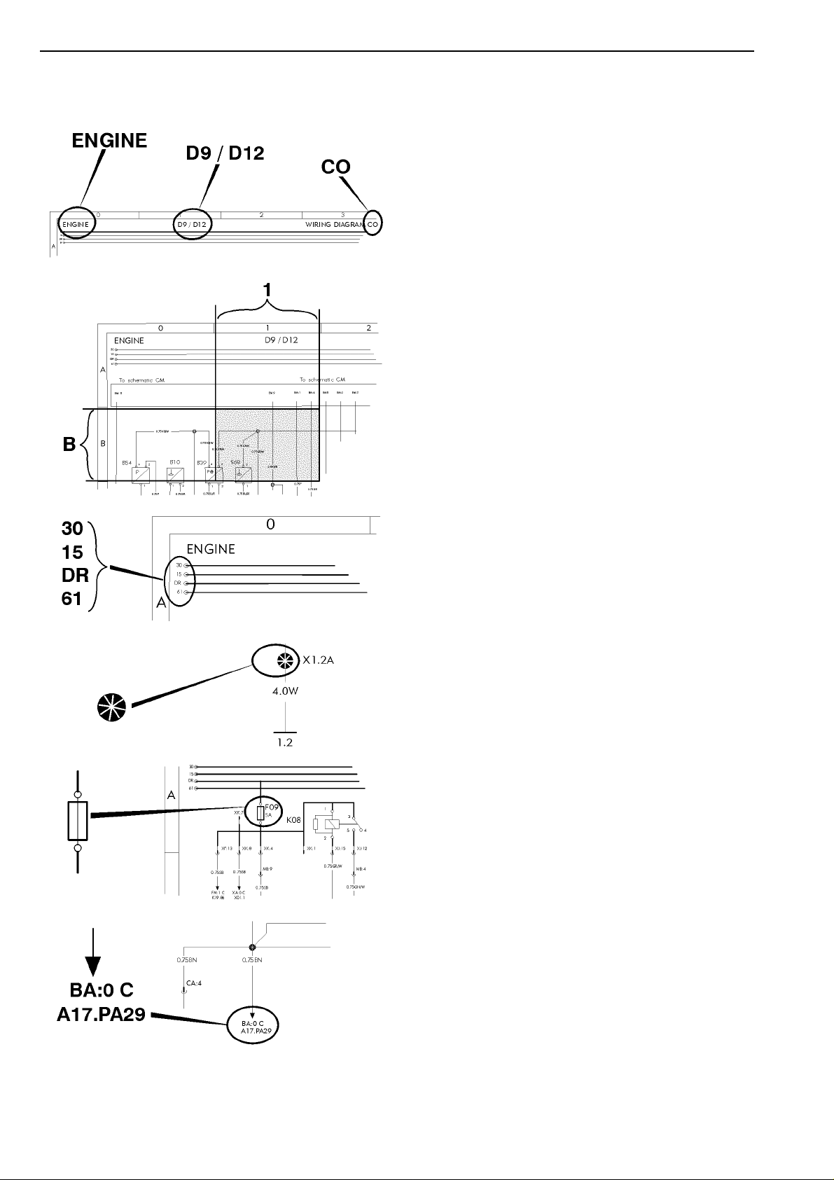
Example of wiring diagram
Component wiring diagram title, variant/subtitle and
symbol.
D
Coordinates (B 1).
30 Voltage battery, kl.30.
15 Voltage with starter key in drive position, kl.15.
DR Voltage with starter key in drive position, preheat
position and start position, kl.DR.
61 Voltage when alternator charges, kl.61.
Splice.
Fuse.
Reference arrow, for diagram BA, coordinates 0 C,
component A17, connector PA pin 29.
2
Group 37 Wiring diagram FM, FH, NH12 Example of wiring diagram
www.cargeek.ir
www.cargeek.ir
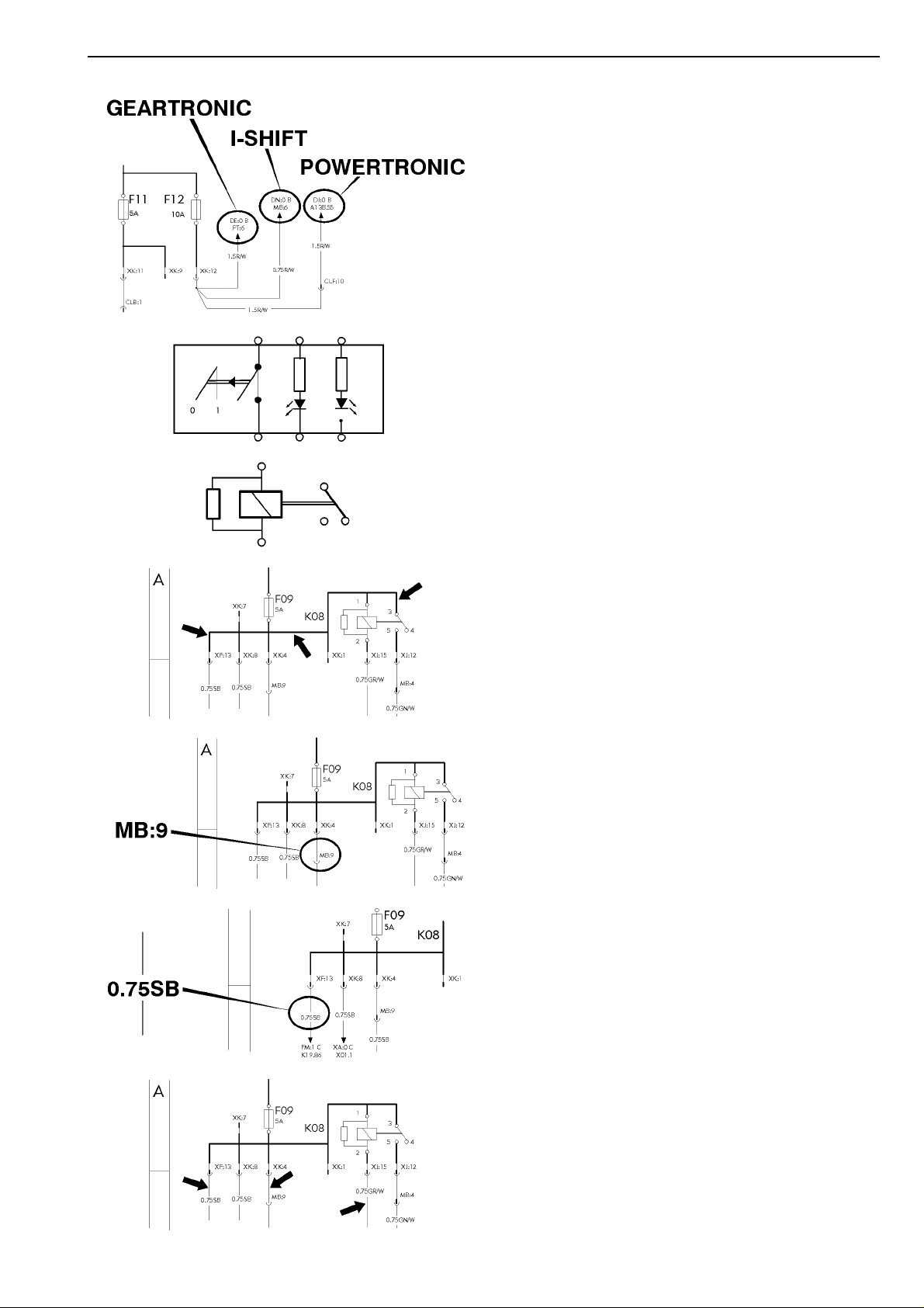
The maximum of variants are drawn, think about that all
wires and components are not standard for all markets or
vehicle models.
D
Switch.
Relay.
Conductor on circuit card.
Connector MB terminal 9.
Wire area and colour.
Thin lines, wires.
3
Group 37 Wiring diagram FM, FH, NH12 Example of wiring diagram
www.cargeek.ir
www.cargeek.ir
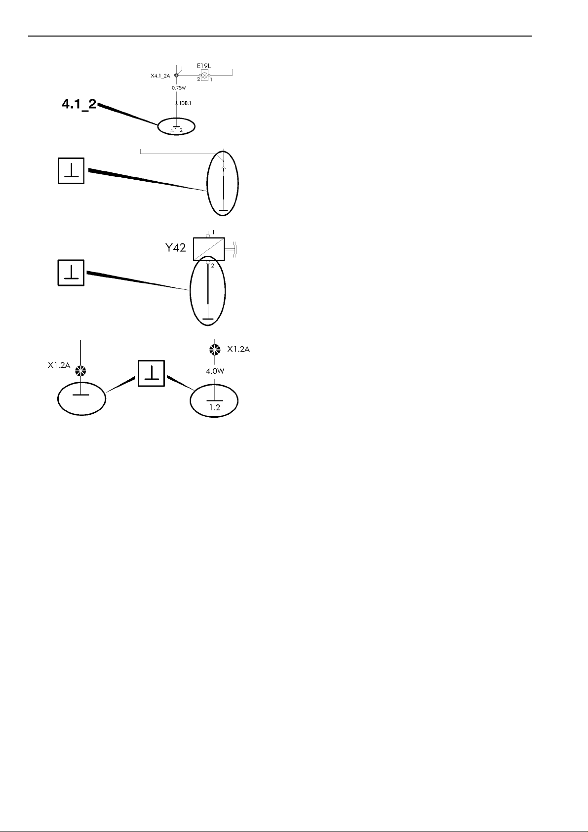
Earth connection point 4, earth connection 1 and wire 2.
Earth connection to circuit card.
D
Earth connection without wire.
Same splice can be drawn on several diagrams. The wire
from the splice to the earth connection point will only be
drawn and coded on one diagram. On the other diagrams
will only the earth connection point be written besides the
splice.
4

Group 37 Wiring diagram FM, FH, NH12 Component wiring diagram index
www.cargeek.ir
www.cargeek.ir
Component wiring diagram index
AA
AB
AC
AE
BA
BE
BI
BM
BN
BU
BX
BY
BZ
BZ RHD
CH
CJ
CO
CP
CV
DC
DI
DI RHD
DM
DP
DQ
DU
EE
EE RHD
EF
EO
EO RHD
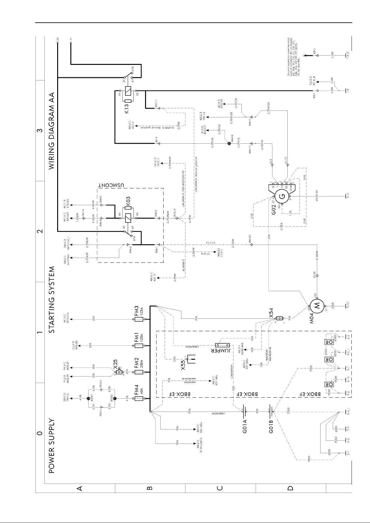
Power supply, starting system ................................................................
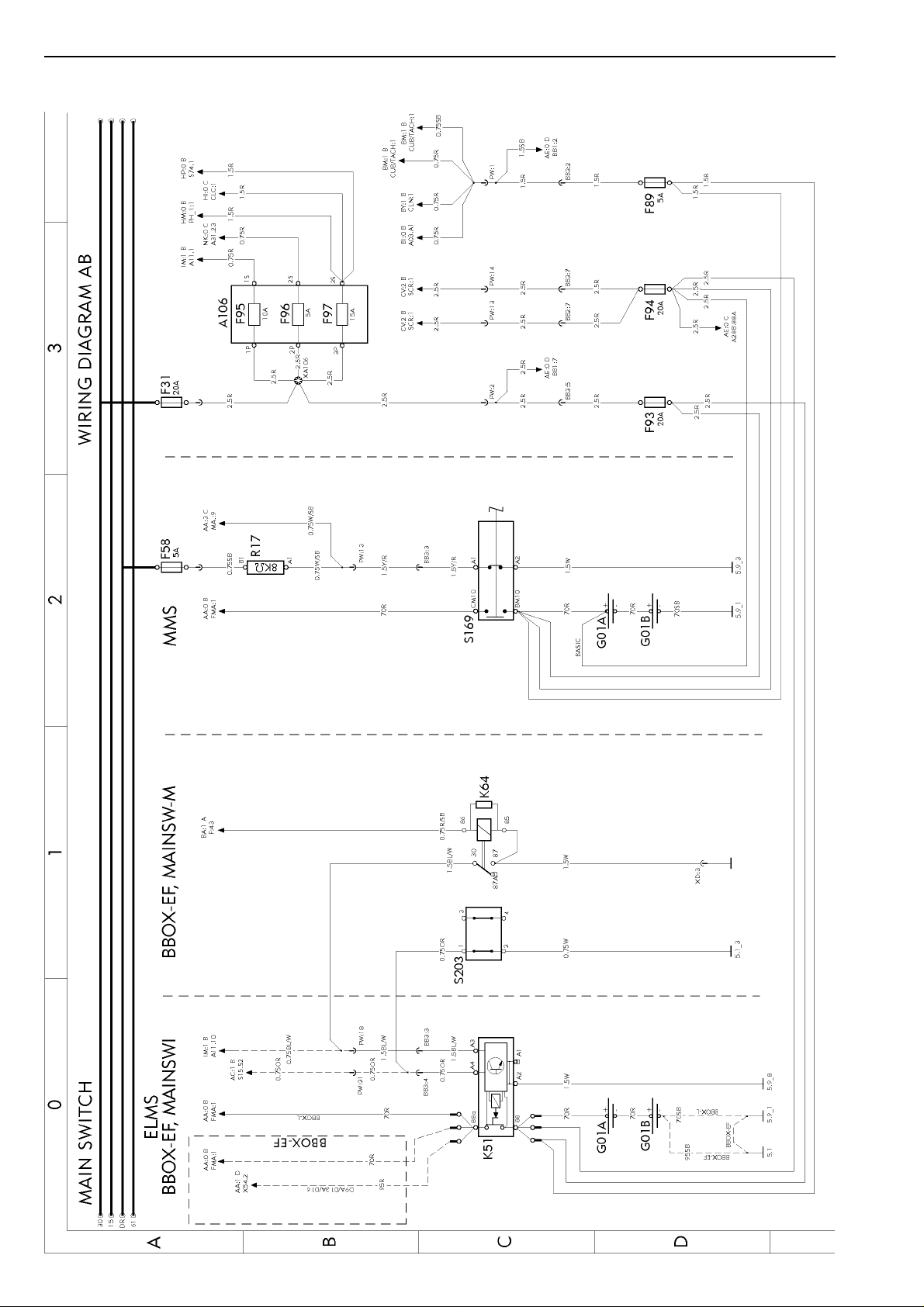
Main switch .............................................................................................
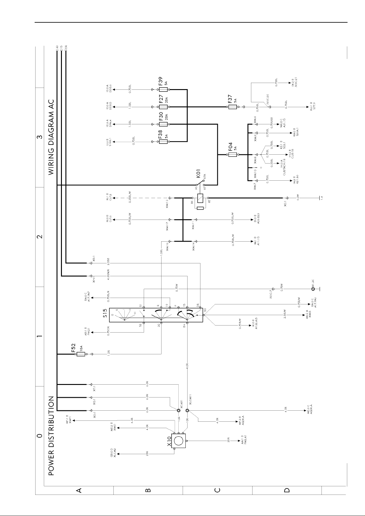
Power distribution ...................................................................................
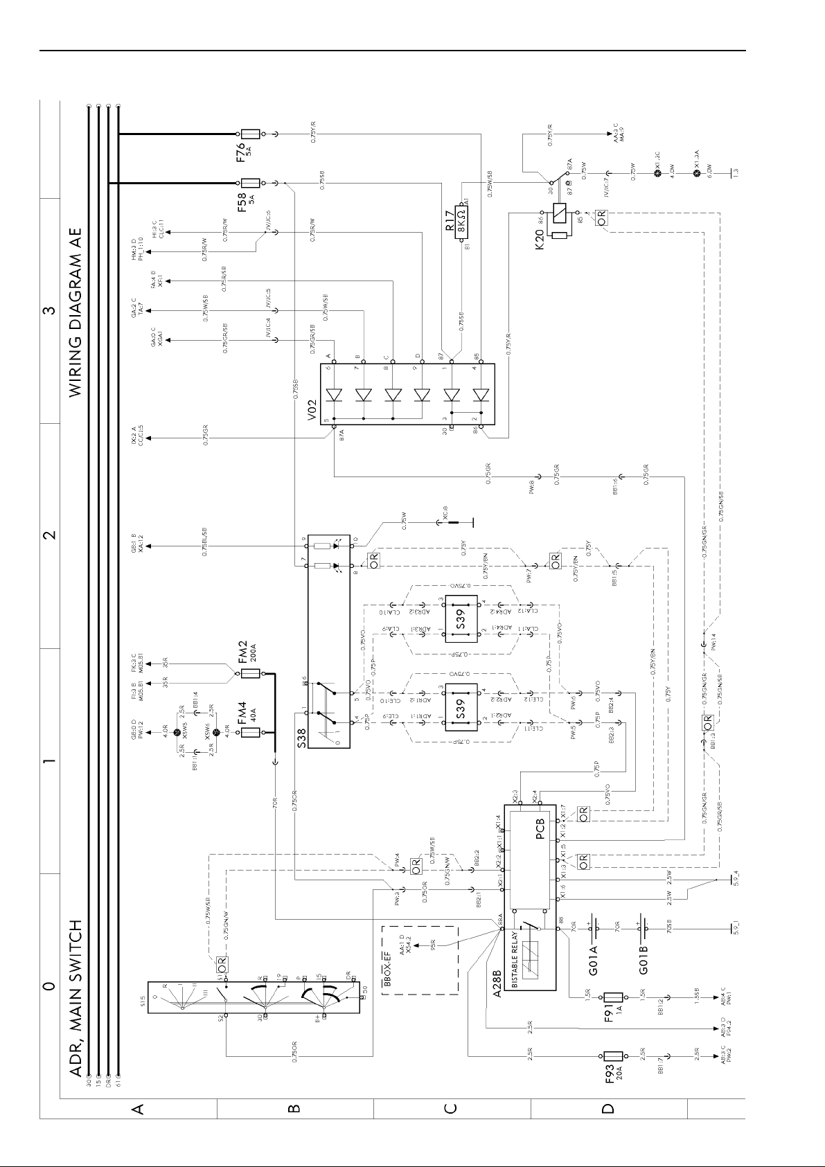
ADR, main switch ...................................................................................
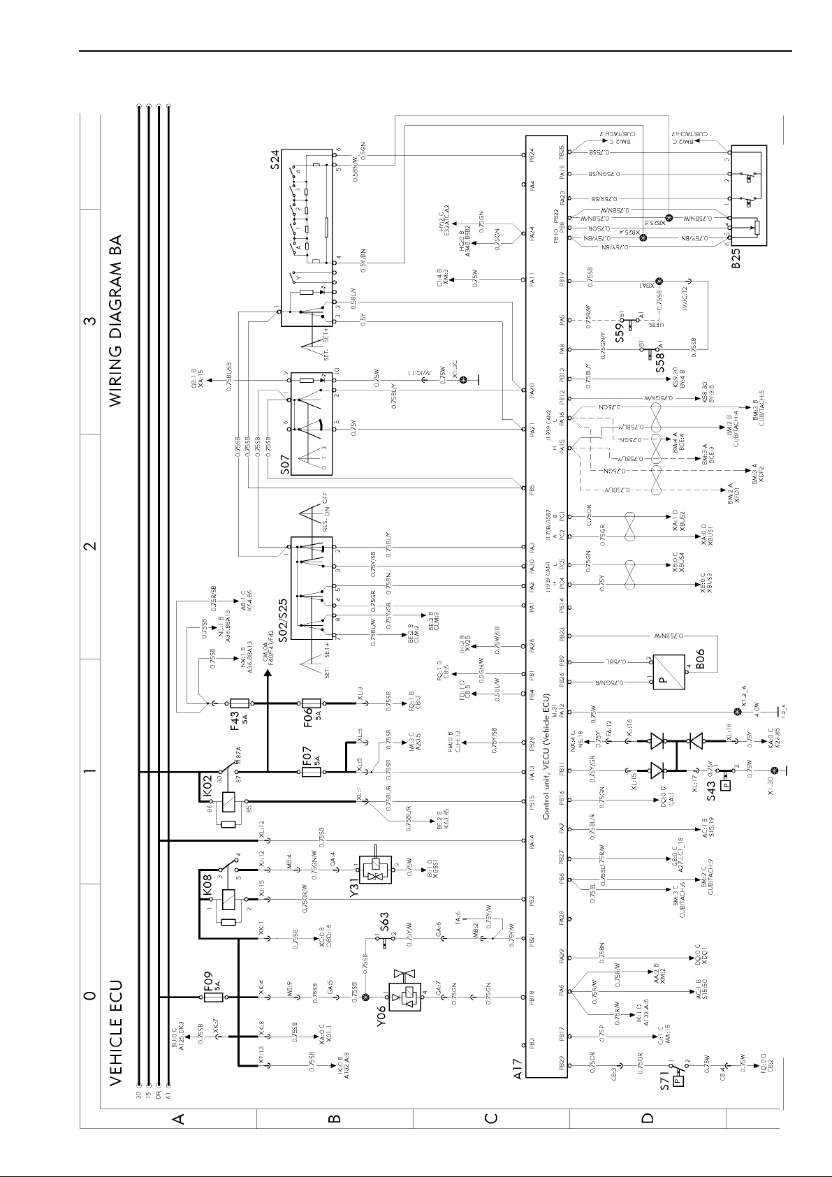
Vehicle ECU ............................................................................................
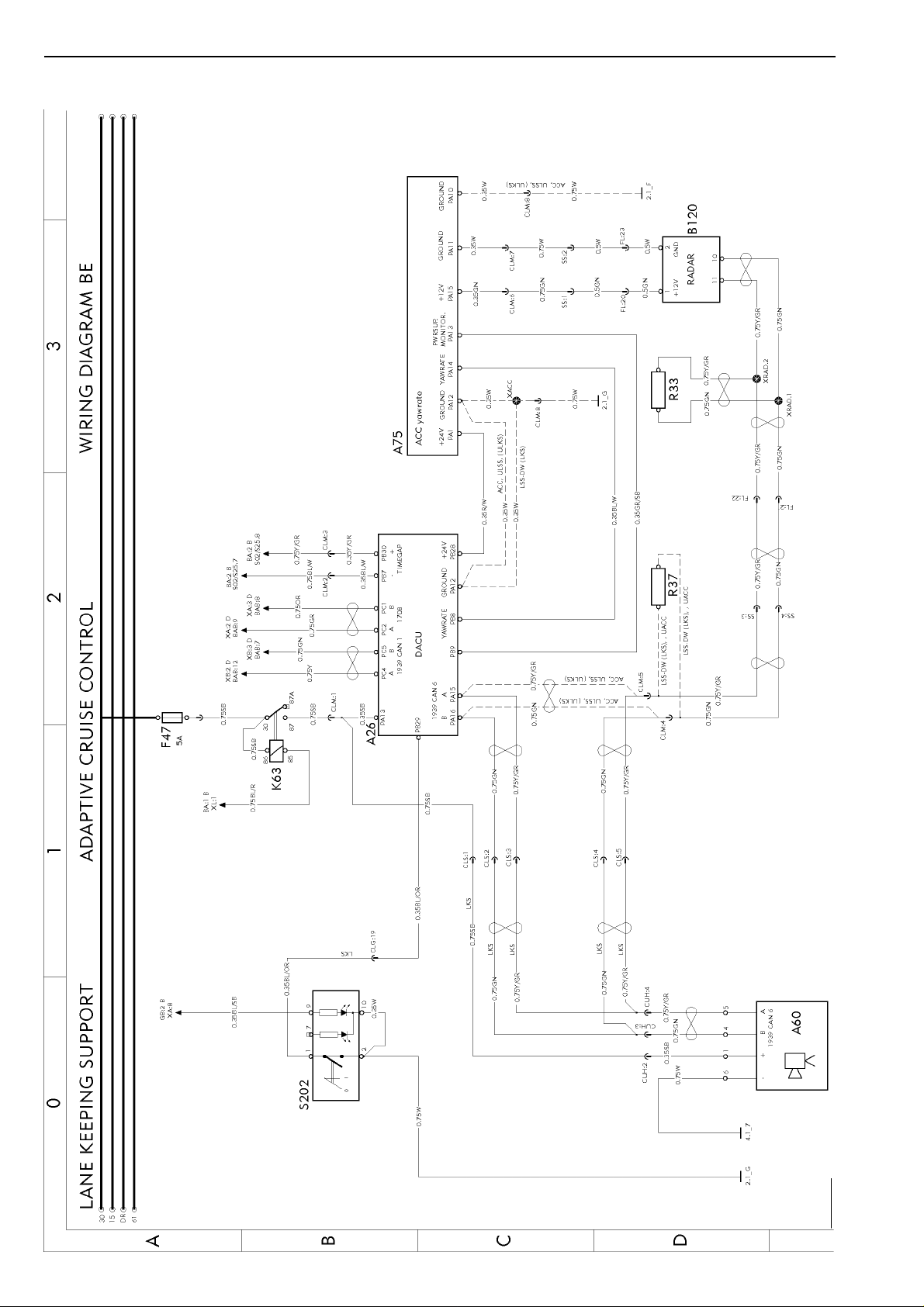
Lane keeping system, ACC Adaptive cruise control ...............................
Instrument cluster ...................................................................................
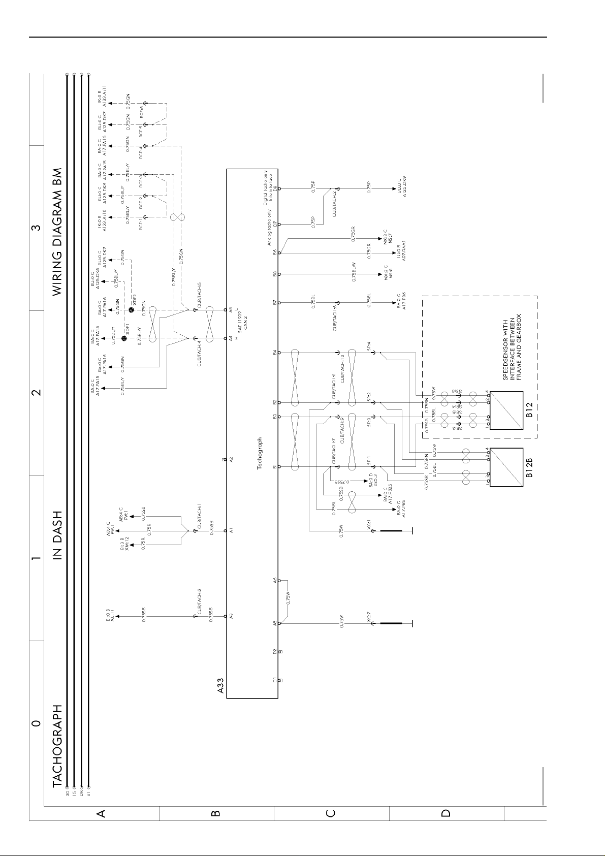
Tachograph in dash ................................................................................ page 16
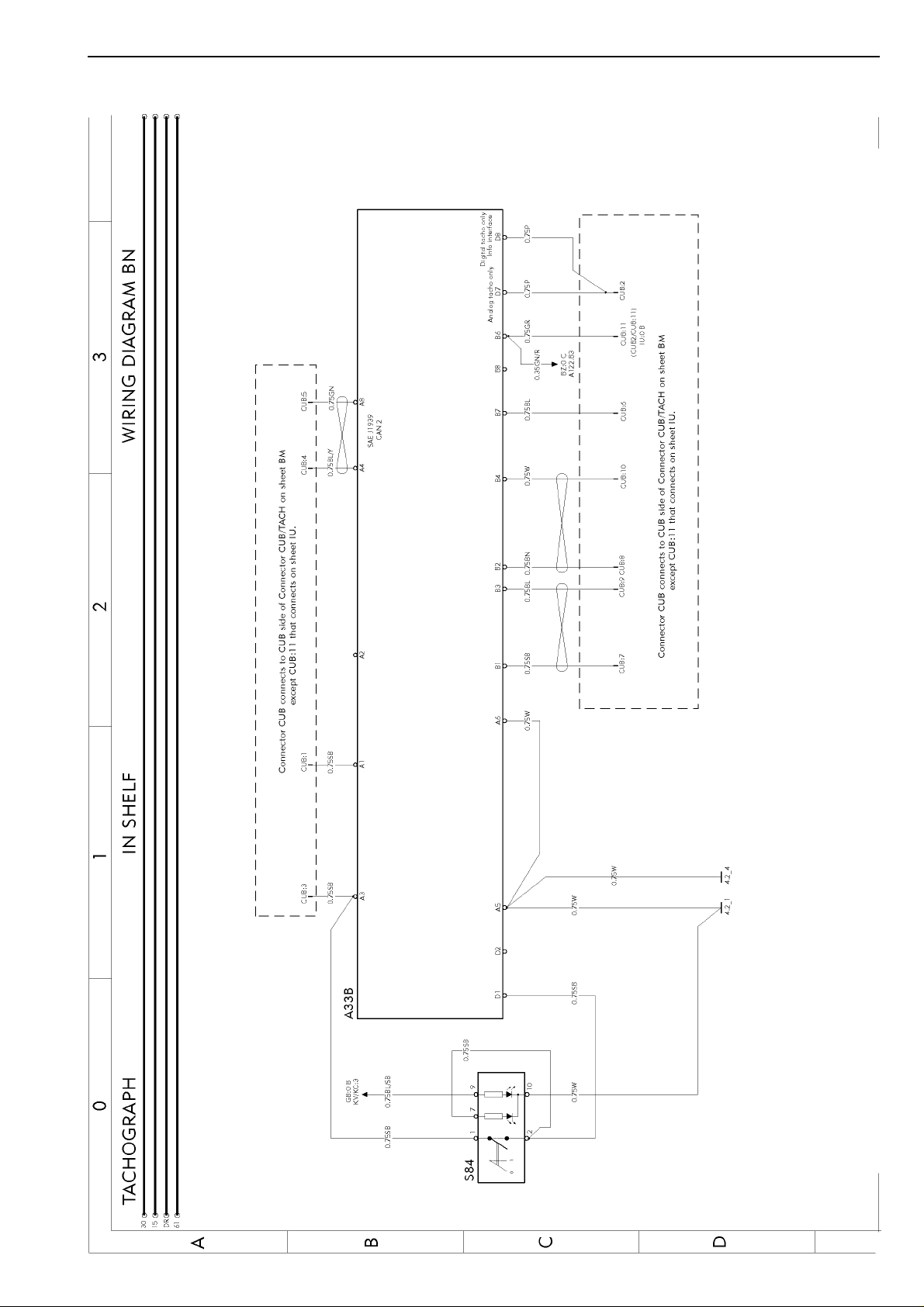
Tachograph in shelf ................................................................................. page 17
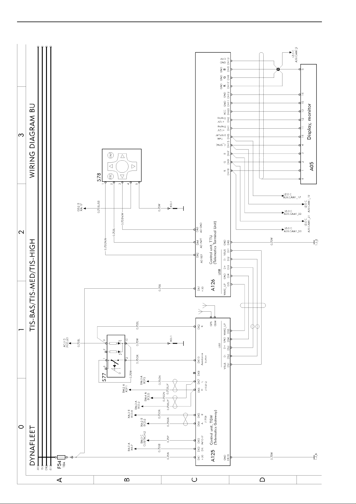
Dynafleet TIS-BAS/TIS-MED/TIS-HIGH .................................................
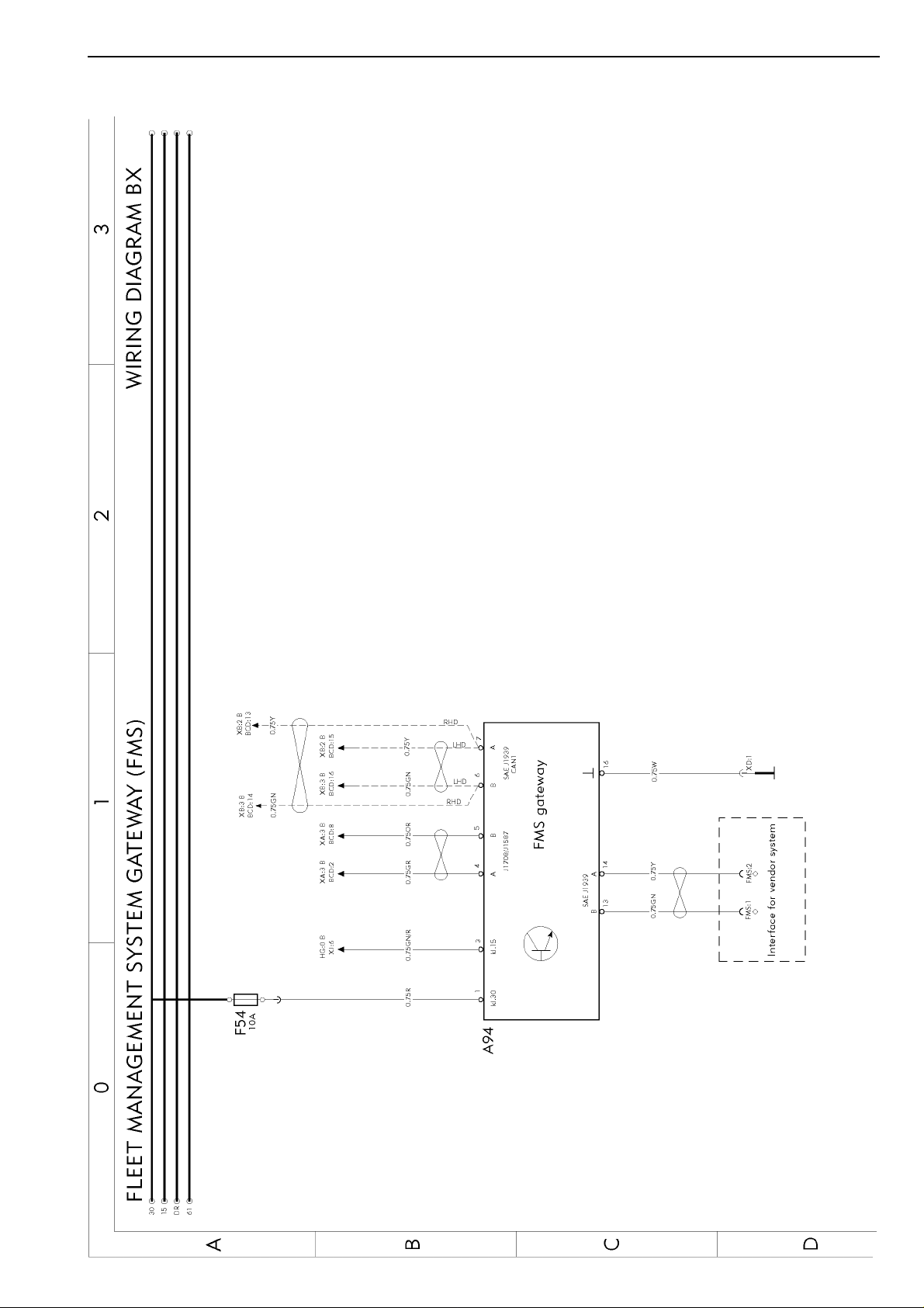
FMS Gateway .........................................................................................
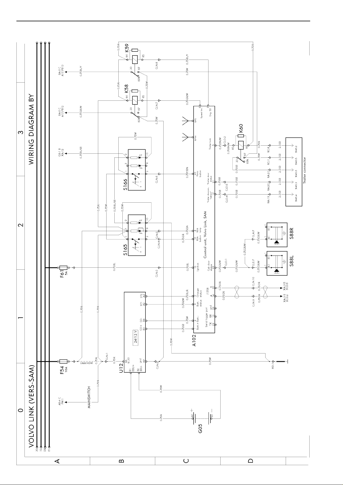
Volvo link (VERS-SAM) ..........................................................................
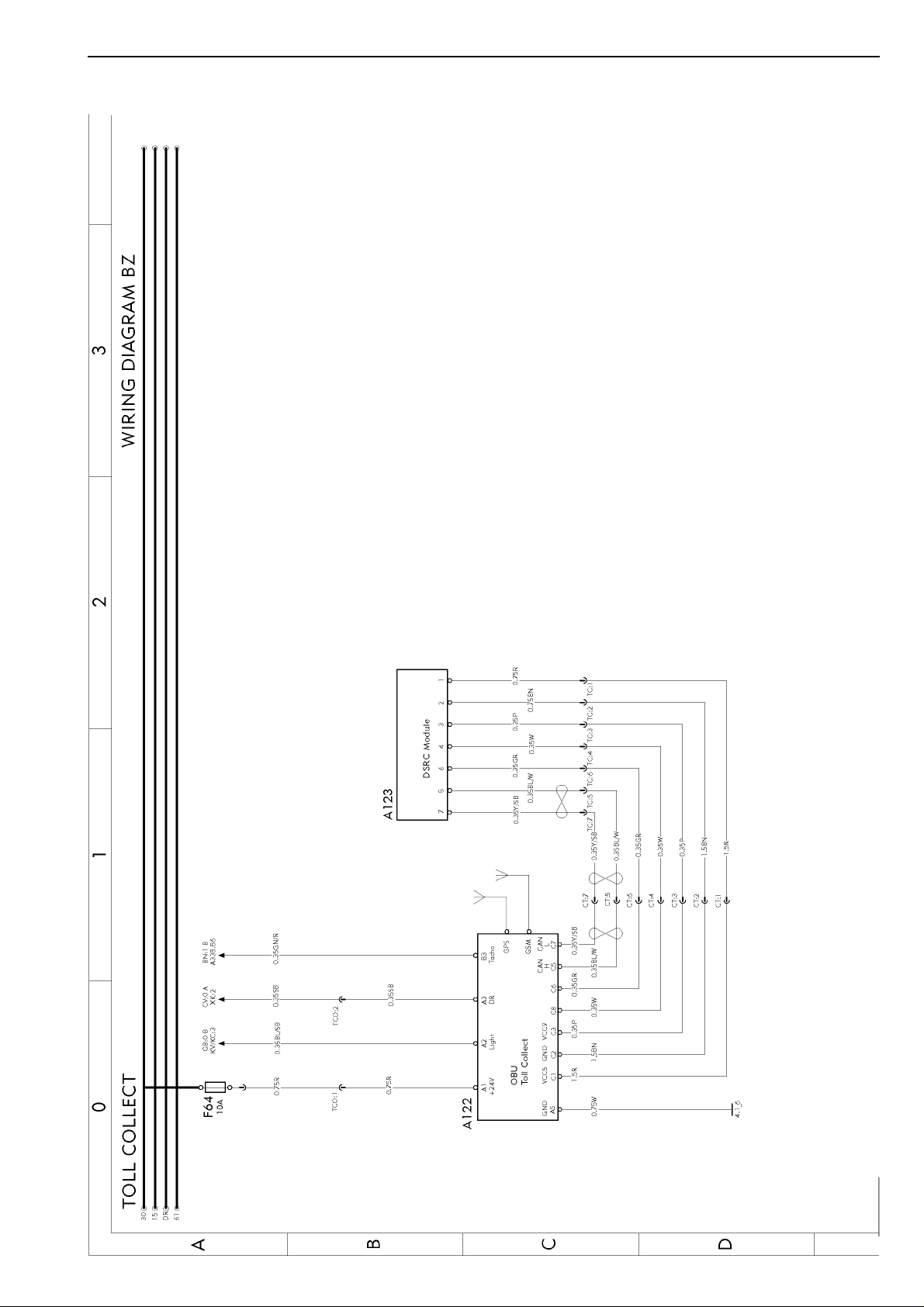
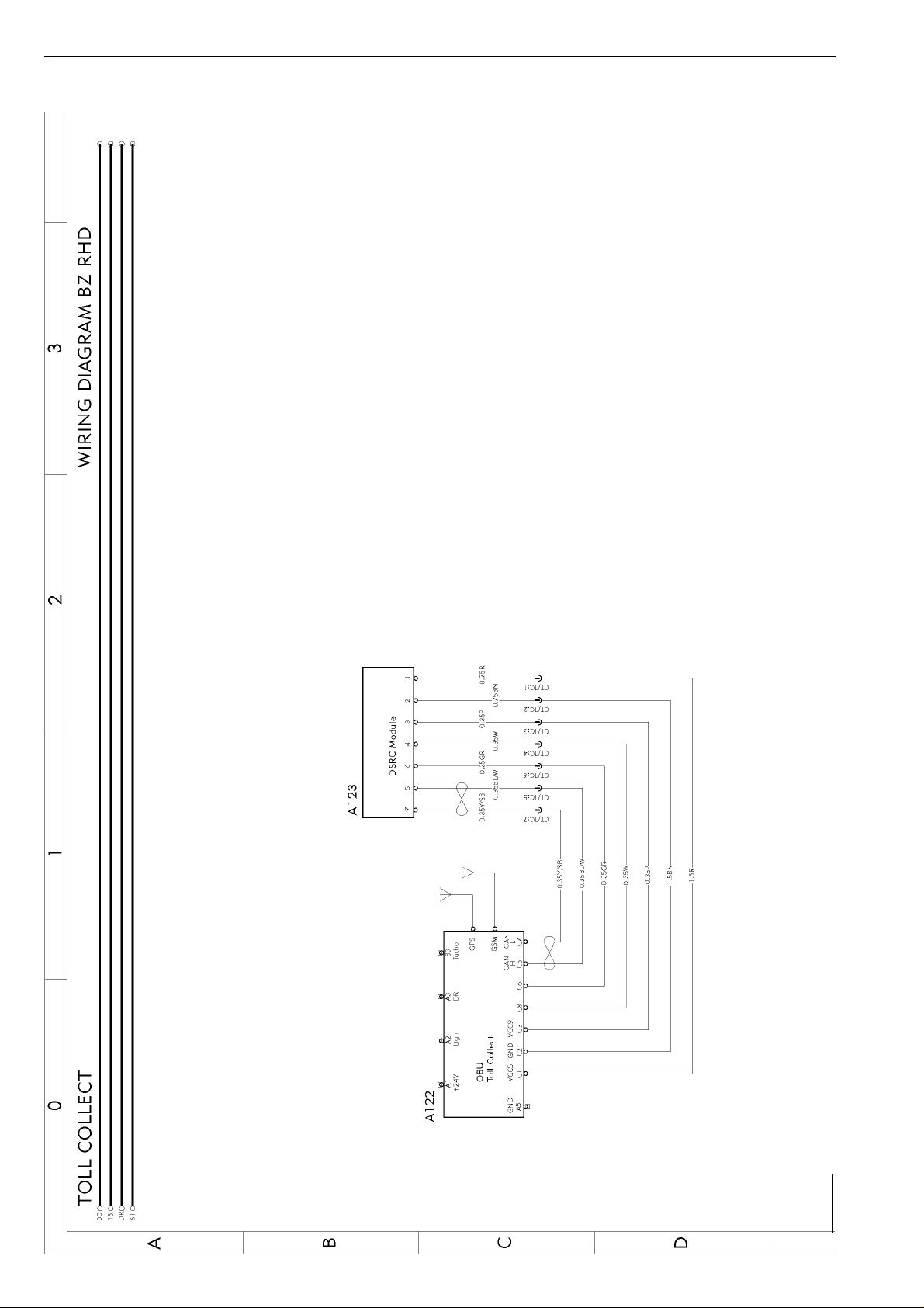
Toll collect ...............................................................................................
Toll collect ...............................................................................................
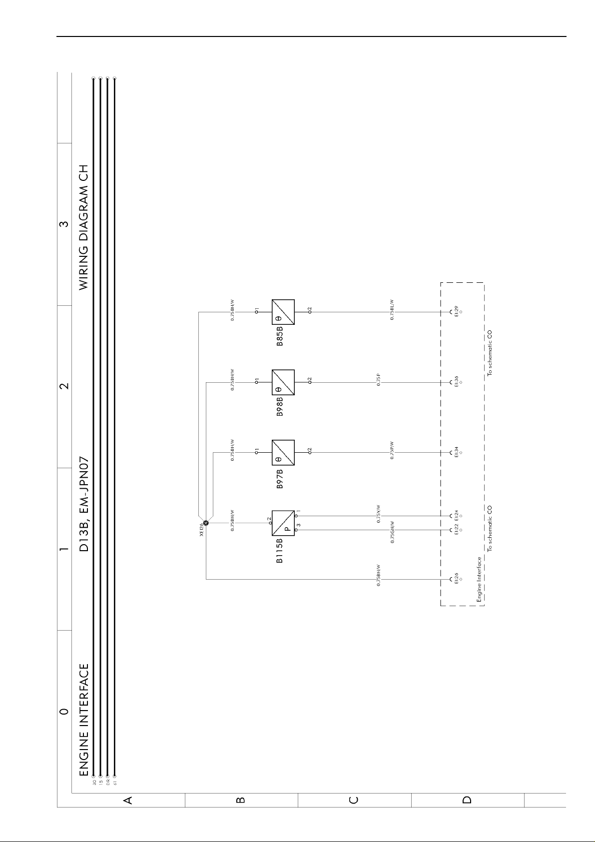
Engine interface D13B, EM-JPN07 ........................................................
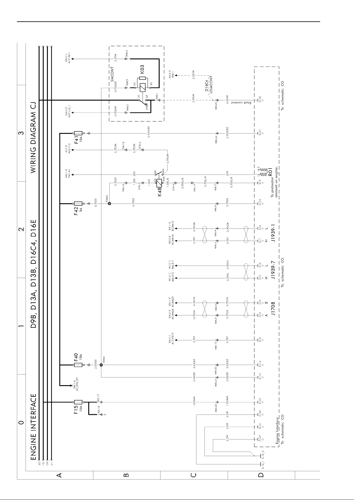
Engine interface D9B, D13A, D13B, D16C4, D16E ................................
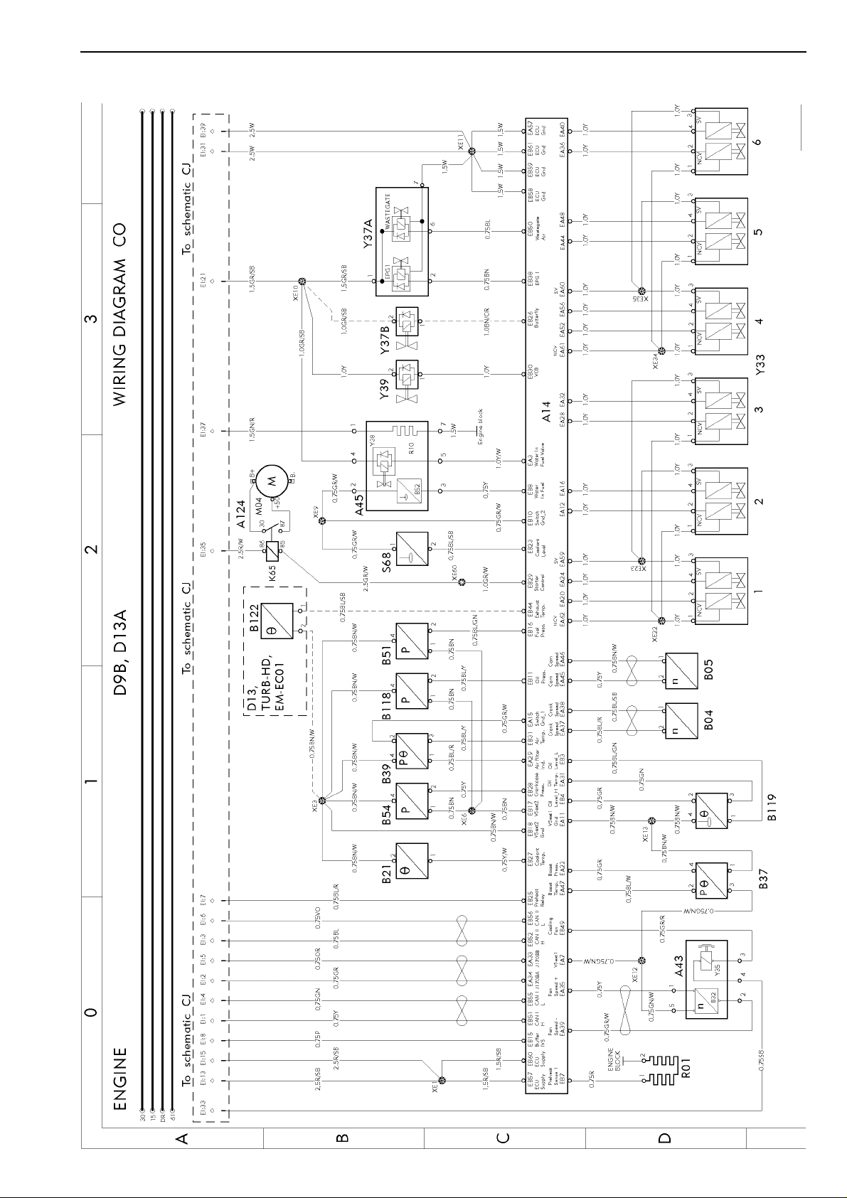
Engine D9B, D13A .................................................................................
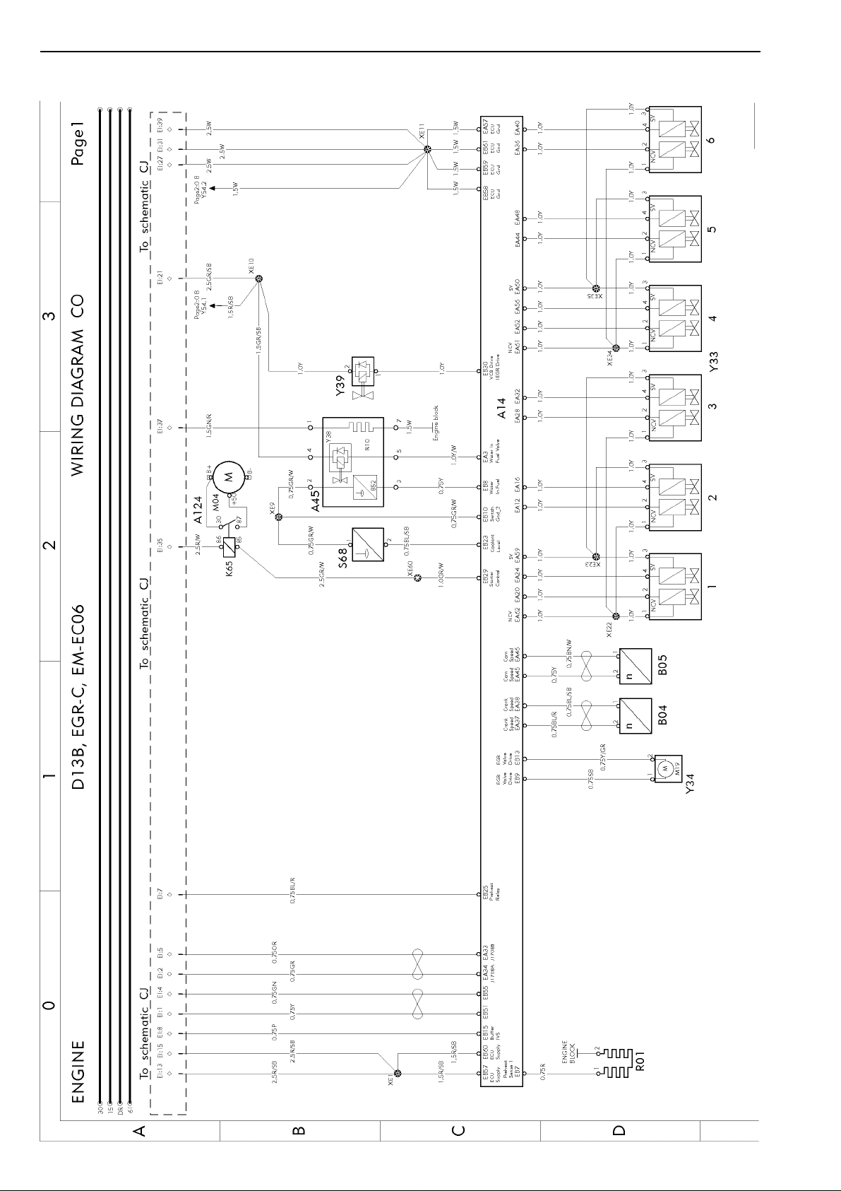
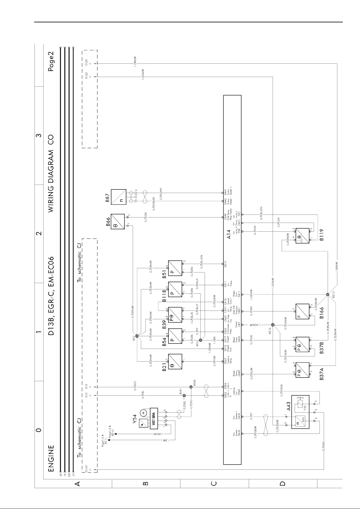
Engine D13B, EGR-C, EM-EC06 ...........................................................
Engine D13B, EGR-C, EM-EC06 ...........................................................
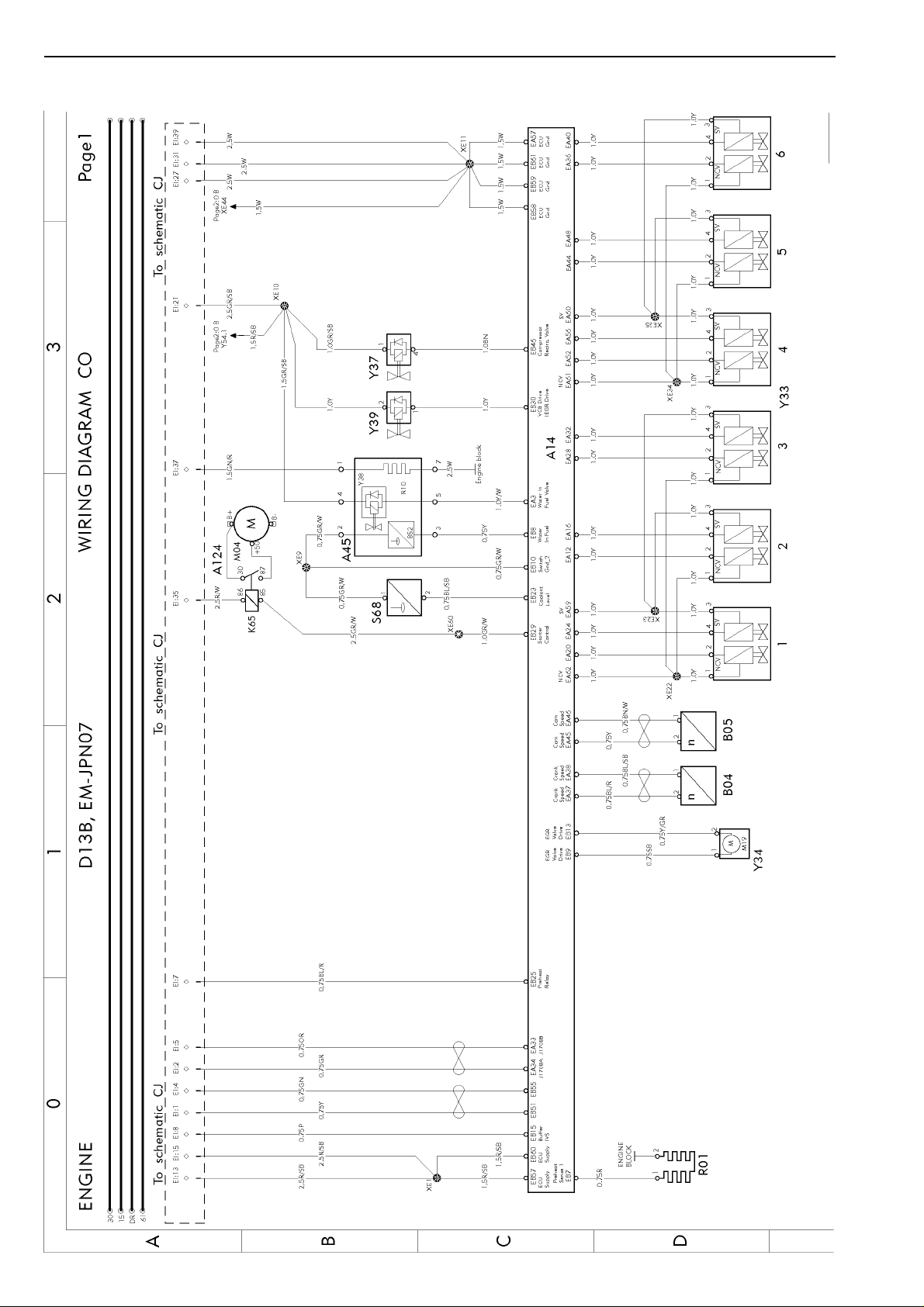
Engine D13B, EM-JPN07 .......................................................................
Engine D13B, EM-JPN07 .......................................................................
Engine D16C4 ........................................................................................
Engine D16E ..........................................................................................
12V trailer ABS converter (AUS only) .....................................................
SCR ........................................................................................................
Gear selector ECU (I-SHIFT/POWERTRONIC) .....................................
Powertronic .............................................................................................
Powertronic .............................................................................................
Retarder manual gearshift ......................................................................
I-shift AT2412C/AT2512C/ATO2512C .....................................................
Power take off .........................................................................................
Diff-lock ...................................................................................................
ABS basic, E-version ..............................................................................
ABS basic, E-version ..............................................................................
ABS 6x2 VERS-SAM ..............................................................................
EBS ECU ................................................................................................
EBS ECU ................................................................................................
D
page 9
page 10
page 11
page 12
page 13
page 14
page 15
page 18
page 19
page 20
page 21
page 22
page 23
page 24
page 25
page 26
page 27
page 28
page 29
page 30
page 31
page 32
page 33
page 34
page 35
page 36
page 37
page 38
page 39
page 40
page 41
page 42
page 43
page 44
page 45
5

Group 37 Wiring diagram FM, FH, NH12 Component wiring diagram index
www.cargeek.ir
www.cargeek.ir
EP
FA
FA RHD
FG
FI
FK
FM
FO
FP
FQ
FU
GA
GB
GC
GC RHD
GE
GF
GG
GH
GK
GL
GM
GQ
GR
GU
HG
HI
HM
HP
HY
HY RHD
HZ
IA
IE
IF
IH
IJ
IK
EBS modulators ......................................................................................
Air-suspension .......................................................................................
Air-suspension .......................................................................................
Load indicator .........................................................................................
Bogie lift A-ride .......................................................................................
Bogie lift A-ride with axle load limiter ......................................................
Axle lock, self steered axle .....................................................................
Electronic steered axle ...........................................................................
Dual steered front axle ...........................................................................
Air dryer ..................................................................................................
Central lubrication system ......................................................................
LCM head lights ......................................................................................
LCM trailer ..............................................................................................
LCM rear lights .......................................................................................
LCM rear lights .......................................................................................
Rear lights overhang ...............................................................................
Rear lights, India/Korea ..........................................................................
Trailer connections, RIGID ......................................................................
Trailer connections, TRACTOR ...............................................................
Trailer connections (AUS only) ...............................................................
Identification lamps .................................................................................
Wiper, washer .........................................................................................
Horn ........................................................................................................
Trailer connections TREL14 ...................................................................
Headlights adjust ....................................................................................
Climate unit, CU,-BAS,-MCC,-ECC ........................................................
Air heater ................................................................................................
Water heater ...........................................................................................
Short stop cab heater .............................................................................
Climat unit, CU,-HEAT,-ACMAN,-ACAUT. ...............................................
Climat unit, CU,-HEAT,-ACMAN,-ACAUT. ...............................................
Air cooler, Brazil ......................................................................................
El. heated/adj. seat ................................................................................
El. heat/adj. mirrors, El. window winders ...............................................
Foldable mirror bracket ...........................................................................
Interior light .............................................................................................
Interior light, storage ...............................................................................
Alcolock, start prevention system ...........................................................
D
page 46
page 47
page 48
page 49
page 50
page 51
page 52
page 53
page 54
page 55
page 56
page 57
page 58
page 59
page 60
page 61
page 62
page 63
page 64
page 65
page 66
page 67
page 68
page 69
page 70
page 71
page 72
page 73
page 74
page 75
page 76
page 77
page 78
page 79
page 80
page 81
page 82
page 83
6

Group 37 Wiring diagram FM, FH, NH12 Component wiring diagram index
www.cargeek.ir
www.cargeek.ir
IM
IQ
IR
IS
IU
IU RHD
IV
IX
IZ
KA
KE
KI
KM
ME
MF
NA
NB
NC
NI
NK
NU
NX
OA
XA
XB
XC
ZA RHD
Central locking, immobiliser ....................................................................
El. sunroof, cig. lighter, refrigerator ........................................................
12V power supply ...................................................................................
SRS. Air-bag ...........................................................................................
Radio ......................................................................................................
Radio ......................................................................................................
Amplifier ..................................................................................................
Integrated telephone ...............................................................................
Backup camera .......................................................................................
Cab tilt ....................................................................................................
Load light, 5:th wheel lamp .....................................................................
Light sign ................................................................................................
Beacon warning light ..............................................................................
Extra fuse block, key switch relay ...........................................................
Extra fuse block, SPDU-S .......................................................................
Body builder (BB), auxsw-6 and swapbody ............................................
Body builder (BB), tailprep and swapbody ..............................................
Body builder (BB), ELCE-CK, BBM, PTO2 .............................................
Extra spotlamps front/roof, max 4x70W ..................................................
Burglar alarm ..........................................................................................
Body builder (BB), SPEED-DU ...............................................................
Body builder (BB), SPDU-S ....................................................................
Tyre pressure monitoring (TPM) .............................................................
Bus J1708/J1587 ....................................................................................
Bus J1939 ...............................................................................................
Bus J1939–7, OBD .................................................................................
Ground/Misc. .........................................................................................
D
page 84
page 85
page 86
page 87
page 88
page 89
page 90
page 91
page 92
page 93
page 94
page 95
page 96
page 97
page 98
page 99
page 100
page 101
page 102
page 103
page 104
page 105
page 106
page 107
page 108
page 109
page 110
7

Group 37 Wiring diagram FM, FH, NH12 Component wiring diagrams
www.cargeek.ir
www.cargeek.ir
Component wiring diagrams
D
8
Group 37 Wiring diagram FM, FH, NH12 Component wiring diagrams
www.cargeek.ir
www.cargeek.ir
D
T3020461
9
Group 37 Wiring diagram FM, FH, NH12 Component wiring diagrams
www.cargeek.ir
www.cargeek.ir
D
10
T3020462
Group 37 Wiring diagram FM, FH, NH12 Component wiring diagrams
www.cargeek.ir
www.cargeek.ir
D
T3020463
11
Group 37 Wiring diagram FM, FH, NH12 Component wiring diagrams
www.cargeek.ir
www.cargeek.ir
D
12
T3020464
Group 37 Wiring diagram FM, FH, NH12 Component wiring diagrams
www.cargeek.ir
www.cargeek.ir
D
T3020465
13
Group 37 Wiring diagram FM, FH, NH12 Component wiring diagrams
www.cargeek.ir
www.cargeek.ir
D
14
T3020466

Group 37 Wiring diagram FM, FH, NH12 Component wiring diagrams
www.cargeek.ir
www.cargeek.ir
D
T3020467
15
Group 37 Wiring diagram FM, FH, NH12 Component wiring diagrams
www.cargeek.ir
www.cargeek.ir
D
16
T3020468
Group 37 Wiring diagram FM, FH, NH12 Component wiring diagrams
www.cargeek.ir
www.cargeek.ir
D
T3019646
17
Group 37 Wiring diagram FM, FH, NH12 Component wiring diagrams
www.cargeek.ir
www.cargeek.ir
D
18
T3020469
Group 37 Wiring diagram FM, FH, NH12 Component wiring diagrams
www.cargeek.ir
www.cargeek.ir
D
T3019047
19
Group 37 Wiring diagram FM, FH, NH12 Component wiring diagrams
www.cargeek.ir
www.cargeek.ir
D
20
T3020623
Group 37 Wiring diagram FM, FH, NH12 Component wiring diagrams
www.cargeek.ir
www.cargeek.ir
D
T3019649
21
Group 37 Wiring diagram FM, FH, NH12 Component wiring diagrams
www.cargeek.ir
www.cargeek.ir
D
22
T3019650
Group 37 Wiring diagram FM, FH, NH12 Component wiring diagrams
www.cargeek.ir
www.cargeek.ir
D
T3020470
23
Group 37 Wiring diagram FM, FH, NH12 Component wiring diagrams
www.cargeek.ir
www.cargeek.ir
D
24
T3020471
Group 37 Wiring diagram FM, FH, NH12 Component wiring diagrams
www.cargeek.ir
www.cargeek.ir
D
T3020472
25
Group 37 Wiring diagram FM, FH, NH12 Component wiring diagrams
www.cargeek.ir
www.cargeek.ir
D
26
T3020473
Group 37 Wiring diagram FM, FH, NH12 Component wiring diagrams
www.cargeek.ir
www.cargeek.ir
D
T3020500
27
Group 37 Wiring diagram FM, FH, NH12 Component wiring diagrams
www.cargeek.ir
www.cargeek.ir
D
28
T3020474
 Loading...