


D2-75

OPERATOR’S MANUAL
D2-55, D2-75
This operator’s manual is also available in the following languages:
Diese Betriebsanleitung ist auch auf
Deutsch erhältlich.
Ein Bestellcoupon ist am Ende der Betriebsanleitung zu finden.
Ce manuel d’instructions peut être
commandé en français.
Vous trouverez un bon de commande à la fin
du manuel d’instructions.
Este libro de instrucciones puede solicitarse en español.
El cupón de pedido se encuentra al final del
libro.
Den här instruktionsboken kan beställas på svenska.
Beställningskupong finns i slutet av instruktionsboken.
Dit instructieboek kan worden besteld
in het Nederlands.
De bestelcoupon vindt u achter in het instructieboek.
Denne instruktionsbog kan bestilles på
dansk.
Bestillingskupon findes i slutningen af instruktionsbogen.
Tämän ohjekirjan voi tilata myös suomenkielisenä.
Tilauskuponki on ohjekirjan lopussa.
Este manual de instruções pode ser
encomendado em português.
O talão de requerimento encontra-se no fim
do manual.
Questo manuale d’istruzioni può essere ordinato in lingua italiana.
7742957 - Downloaded from www.volvopenta.com 22/09/2008 11:33:23
Il tagliando per l’ordinazione è riportato alla
fine del manuale.
Diesel engine exhaust and some of its constituents are known
to the State of California to cause cancer, birth defects, and
other reproductive harm.
Бхфь фп егчейсЯдйп чсЮузт дйбфЯиефбй
уфзн бгглйкЮ глюууб.
Гйб нб рбсбггеЯлефе Энб бнфЯфхрп,
ухмрлзсюуфе фз цьсмб рпх всЯукефбй уфп
фЭлпт бхфпэ фпх егчейсйдЯпх чсЮузт.
CALIFORNIA
Proposition 65 Warning
7742957 - Downloaded from www.volvopenta.com 22/09/2008 11:33:23
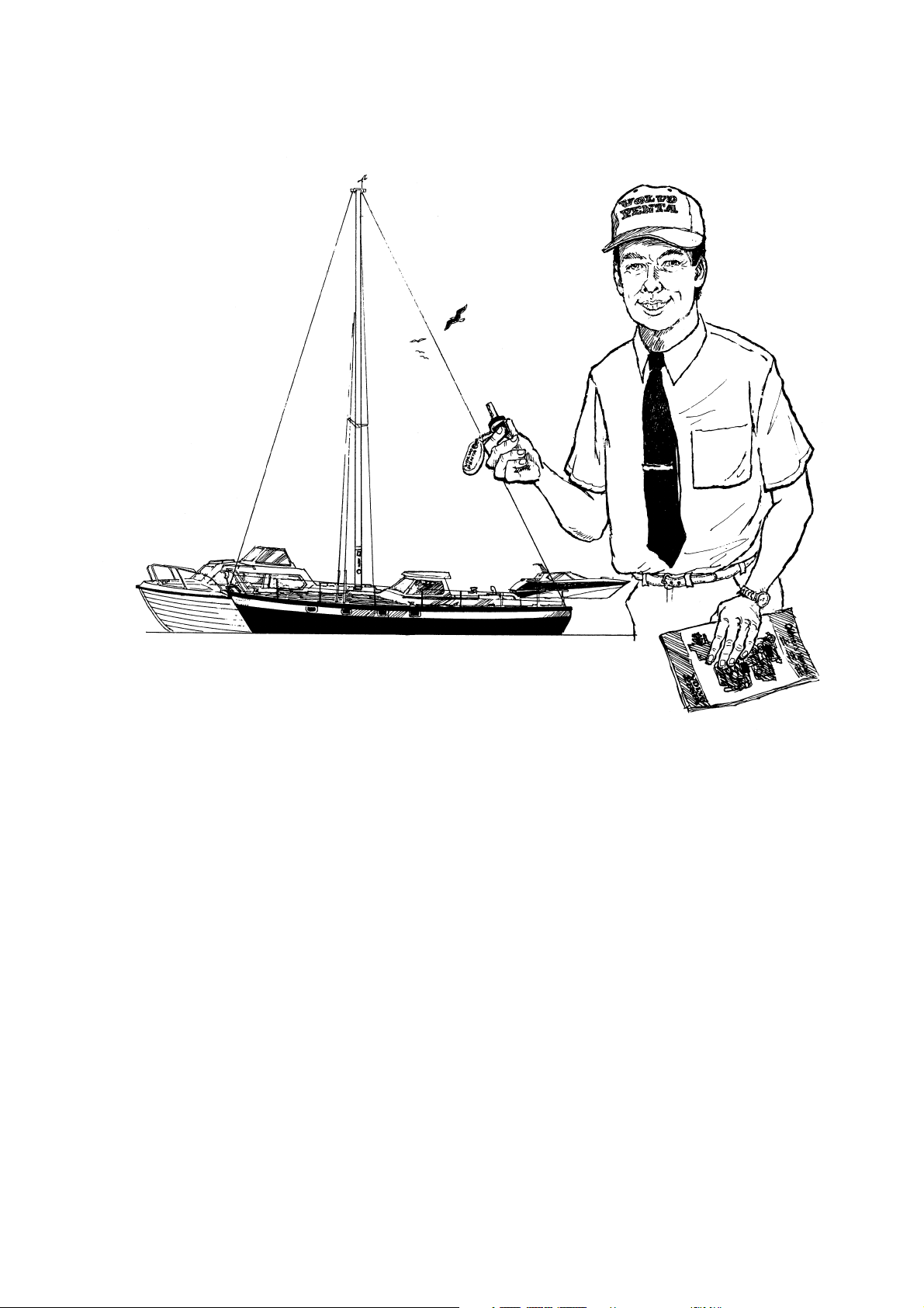
Welcome aboard
Volvo Penta marine engines are used all over the world today. They are used in all possible operating conditions for professional as well as leisure purposes. That’s not surprising.
After more than 90 years as an engine manufacturer and after delivering over 500,000
marine engines, the Volvo Penta name has become a symbol of reliability, technical innovation, top of the range performance and long service life. We also believe that this is
what you demand and expect of your Volvo Penta engine.
We would like you to read this operator’s manual thoroughly and consider the advice we
give on running and maintenance before you cast off on your maiden voyage so that
you will be ensured of fulfilling your expectations.
Best regards
AB VOLVO PENTA
1

Contents
Safety Information ............................................... 3–7
Introduction .........................................................8–9
Running-in ............................................................ 8
Fuel and oil types ................................................ 8
Certified engines .................................................. 9
Warranty information ............................................ 9
Introduction ..................................................... 10–14
D2-55 ................................................................. 12
D2-75 ................................................................. 12
Identification numbers ........................................ 14
Instrumentation ............................................... 15–18
Controls ................................................................ 19
Starting the engine. ........................................ 20–23
Preparations and starting ................................... 20
Starting the engine using auxiliary batteries ....... 23
Operation ......................................................... 24–25
Checking instruments ........................................ 24
Cruising speed ................................................... 24
Maneuvering ...................................................... 25
When sailing ...................................................... 25
Maintenance schedule .................................... 26–27
Maintenance and care ..................................... 28–53
Engine, general .................................................. 28
Lubrication system ............................................. 32
Freshwater system ............................................ 33
Seawater system ............................................... 36
Fuel system ....................................................... 40
Electrical system ............................................... 42
Electrical components diagram .......................... 47
S drive and reverse gear .................................... 48
Laying up/Launching ...................................... 52–55
Inhibiting ............................................................ 52
Bringing out of storage ....................................... 54
Painting the drive and underwater hull ................ 55
Fault-tracing ......................................................... 56
Technical Data ................................................. 57–58
General .............................................................. 57
Lubrication, cooling and electrical systems ........ 57
S drive and reverse gear .................................... 58
Fuel specification ............................................... 58
Stopping the engine ............................................ 26
After stopping the engine ................................... 26
Laying up ........................................................... 26
7742957 - Downloaded from www.volvopenta.com 22/09/2008 11:33:23
Cold weather precautions ................................... 26
All rights to changes or modifications reserved. Printed on environmentally friendly paper.
2
(Cover: Department of transport (shipping), license 9809095)
© 2003 AB VOLVO PENTA
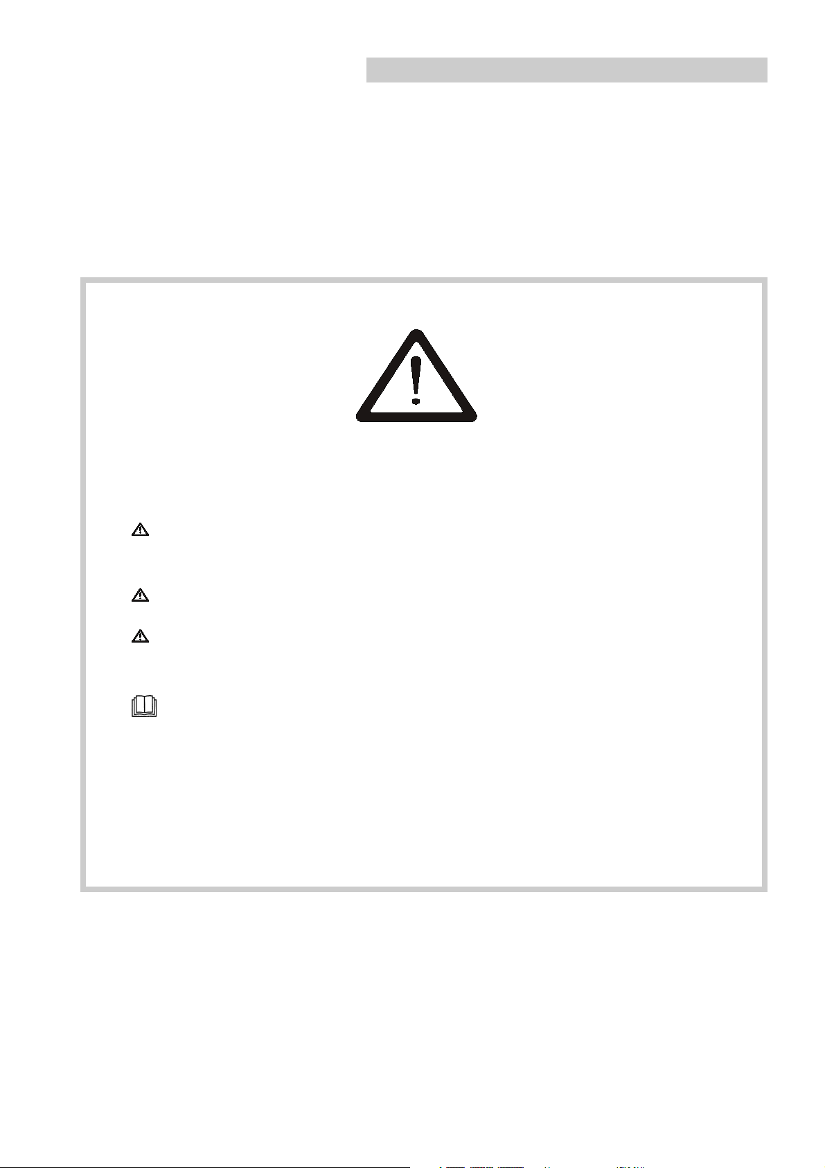
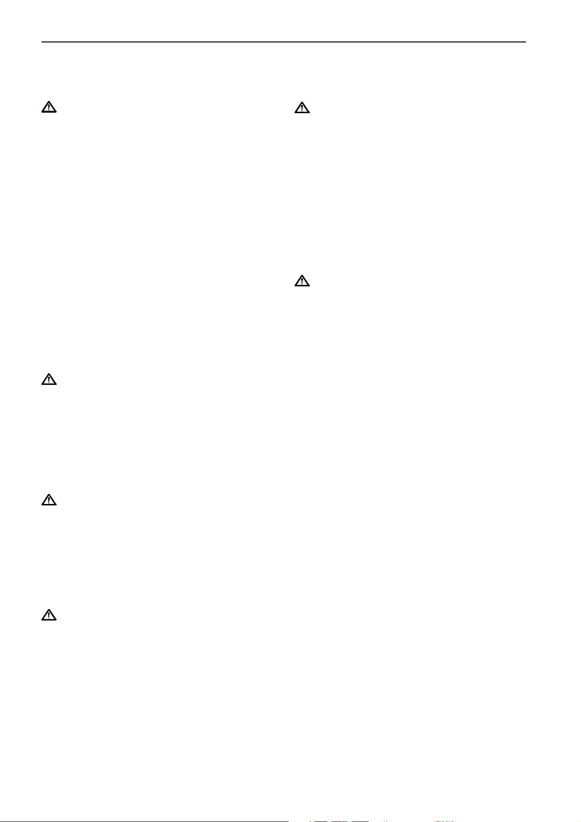
Safety Precautions
Read this chapter carefully. It concerns your safety. This chapter describes how safety information is presented
in the Operator's Manual and on the engine itself. It also gives a general account of basic safety precautions to
be taken when operating the boat and maintaining the engine.
Check that you have the correct Operator's Manual before you read on. If this is not the case please contact your Volvo Penta dealer.
If operations are performed incorrectly this could result in personal injury, or damage to
property or the engine. Read the Operator's Manual carefully before operating or servicing
the engine. If anything is unclear please contact your Volvo Penta dealer for assistance.
This symbol is used in the book and on the engine to make you aware of safety information.
Always read these safety precautions very carefully.
In the Operator's Manual warning texts have the following priority:
WARNING! If these instructions are not followed there is a danger of personal injury, exten-
sive damage to the product or serious mechanical malfunction.
IMPORTANT! Used to draw your attention to something that can cause damage, product
malfunction or damage to property.
NOTE!Used to draw your attention to important information that will facilitate work or operations.
7742957 - Downloaded from www.volvopenta.com 22/09/2008 11:33:23
This symbol is used in certain cases on our products and refers to important information in
the Operator's Manual. Ensure that warning and information symbols on the engine and transmission are always visible and legible. Replace symbols that have been damaged or painted over.
3
Safety Information
Safety precautions to be taken when operating the boat
Your new boat
Read Operator's Manuals and other information
supplied with your new boat. Learn to operate the
engine, controls and other equipment safely and
correctly.
If this is your first boat, or is a boat type with which
you are not familiar, we recommend that you practice
controlling the boat in peace and quiet. Learn how the
boat behaves at different speeds, weather conditions
and loads before casting off for your “real” maiden
voyage.
Remember that the person driving a boat is legally
required to know and follow the current rules regarding
traffic and safety at sea. Make sure you know the
rules that apply to you and the waters you are sailing
in by contacting the relevant authorities or organization.
A good piece of advice is to take a course in seamanship. We recommend that you contact your local
boating organization to find a suitable course.
Accidents
Statistics show that poor maintenance of boats and
engines and a lack of safety equipment are often the
cause of accidents at sea.
Refueling
When refueling there is always a danger of fire and
explosion. Smoking is forbidden and the engine must
be switched off.
Never overfill the tank. Close the fuel tank filler cap
properly.
Only use the fuel recommended in the Operator's
Manual. The wrong grade of fuel can cause operating
problems or cause the engine to stop. On a diesel
engine poor quality fuel can cause the control rod to
seize and the engine to overrev with a resultant risk of
damage to the engine and personal injury.
Do not start the engine
Do not start or run the engine with a suspected fuel or
LPG leak in the boat, when you are close to or in a
discharge of explosive media, etc. There is a risk for
fire and/or explosion in explosive surroundings.
Ensure that your boat is maintained in accordance
with the relevant Operator's Manual and that the
necessary safety equipment is on-board and is
serviceable.
7742957 - Downloaded from www.volvopenta.com 22/09/2008 11:33:23
Daily checklist
Make a habit of checking the engine and engine
compartment visually before operating the boat
(before the engine is started) and after operating the
boat (after the engine has been stopped). This will
help you to quickly detect fuel, coolant and oil leaks
and spot anything else unusual that has, or is about to
happen.
Maneuvering
Avoid violent and unexpected changes in course and
gear engagement. This could cause someone on the
boat to lose their balance and fall over or overboard.
A rotating propeller can cause serious injury. Check
that nobody is in the water before engaging ahead or
astern. Never drive near bathers or in areas where
people could be in the water.
Avoid trimming an outboard drive too much, as
steering will be severely reduced.
4
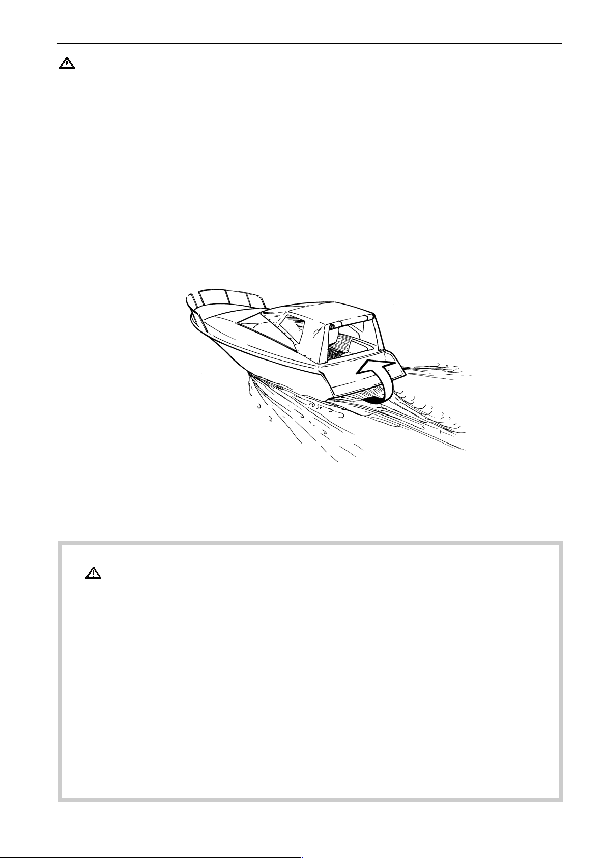
Carbon monoxide poisoning
When a boat is moving forward backwash is caused
behind the boat. Sometimes this backwash can be so
powerful that exhaust gases can be sucked into the
cabin or seating well on the boat with the resulting risk
of carbon monoxide poisoning for those on boar d.
The backwash problem is greatest with high, broad
boats with a squared stern. But other types of boat
can also have backwash problems under certain
conditions, for example when running with an awning
rigged. Among other factors that can increase the
backwash effect are wind conditions, load distribution,
the sea running, trim, open hatches and valves.
Safety Information
Most modern boats are designed in such a way that
problems with backwash are extremely unusual.
Should a backwash problem occur do not open
hatches or valves in the forward part of the boat. This
will only increase backwash. Try changing speed, trim
or load distribution in the boat instead. In addition take
down, open or change the rigging of the awning in
some other way if an awning is rigged. Contact the
dealer where the boat was purchased to get more
information on how to solve this problem should it
occur on your boat.
7742957 - Downloaded from www.volvopenta.com 22/09/2008 11:33:23
Checklist
● Safety equipment: Life jackets for all passengers, communication equipment, emergency rockets,
approved fire extinguisher, first-aid equipment, life belt, anchor, paddle, torch etc.
● Replacement parts and tools: impeller, fuel filters, fuses, tape, hose clamps, engine oil, propeller
and tools for any repairs that might have to be carried out.
● Get out your charts and go over the planned route. Calculate distance and fuel consumption.
Listen to the weather reports
● Make sure that relations or contact persons are informed when planning a longer voyage. Remem-
ber to inform them if your plans have changed or been delayed.
● Tell your passengers and crew where the safety equipment is stored and how to operate it. Make
sure you are not the only person on board who knows how to start the boat and operate it safely.
The list should be supplemented because the requirement for safety equipment varies depending on
the boat type and how it is used etc. We recommend that you contact a local boating or maritime
safety organization for more detailed marine safety information.
5

Safety Information
Safety precautions for maintenance and service operations
Preparations
Knowledge
The Operator's Manual contains instructions on how to
carry out general maintenance and service operations
safely and correctly. Read the instructions carefully
before starting work.
Service literature covering more complicated operations is available from your Volvo Penta dealer.
Never carry out any work on the engine if you are
unsure of how it should be done, contact your Volvo
Penta dealer who will be glad to offer assistance.
Stop the engine
Stop the engine before opening or removing engine
hatches. Unless otherwise specified all maintenance
and service must be carried out with the engine
stopped.
To prevent accidental start of the boat engine remove
the ignition key, turn off the power supply to the
engine at the main switch and lock it in the OFF
position before starting work. Put up a warning sign in
the control position that work on the engine is being
carried out.
Approaching or working on an engine that is running is
a safety risk. Loose clothing, hair, fingers or a
dropped tool can be caught in the rotating parts of the
engine and cause serious personal injury. Volvo Penta
recommend that all servicing with the engine running
be undertaken by an authorized Volvo Penta workshop.
7742957 - Downloaded from www.volvopenta.com 22/09/2008 11:33:23
Lifting the engine
When lifting the engine use the lifting eyes installed
on the engine (reverse gear where installed). Always
check that lifting equipment is in good condition and is
strong enough for the lift (engine weight with any extra
equipment). For safety’s sake lift the engine using an
adjustable lifting beam. All chains and cables should
run parallel to each other and as perpendicular as
possible in relation to the top of the engine. Bear in
mind that extra equipment installed on the engine may
alter its center of gravity. Special lifting equipment
may then be required in order to maintain the correct
balance and make the engine safe to handle. Never
carry out work on an engine suspended on a hoist.
Before starting the engine
Reinstall all guards removed during service operations
before starting the engine. Check that no tools or
other items have been left on the engine.
Never start a turbocharger engine without installing the
air cleaner (ACL). The rotating compressor in the
turbocharger can cause serious personal injury.
Foreign objects can also be sucked in and cause
mechanical damage to the unit.
Fire and explosion
Fuel and lubrication oil
All fuel, most lubricants and many chemicals are
inflammable. Read and follow the instructions on the
packaging.
When carrying out work on the fuel system make sure
the engine is cold. A fuel spill onto a hot surface or
electrical components can cause a fire.
Store fuel soaked rags and other flammable material
so that there is no danger of them catching fire. In
certain conditions oil-soaked rags can spontaneously
ignite.
Do not smoke when filling fuel, oil or in proximity of a
filling station or in the engine room.
Non-original components
Components used in the fuel and ignition system
(gasoline engines) and electrical systems on Volvo
Penta products are designed and constructed to
minimize the risk of fire and explosion.
Using non-original Volvo Penta parts can result in fire
or explosion on board.
Batteries
The batteries contain and give off oxyhydrogen gas,
especially during charging. This gas is easily ignited
and highly flammable.
Do not under any circumstances smoke or use naked
flame or allow sparks in the vicinity of the batteries or
battery compartment.
Incorrectly connecting a battery terminal cable or
jump-start cable can cause a spark which in turn can
be sufficient to cause an explosion.
Start spray
Never use start spray or similar agents to start an
engine equipped with air pre-heating (glow plugs/
starter element). The starter element may cause an
explosion in the inlet manifold. Danger of personal
injury.
6
Safety Information
Hot surfaces and fluids
There is always a risk of burns when working with a
hot engine. Beware of hot surfaces. For example: the
exhaust pipe, turbocharger (TC), oil pan, charge air
pipe, starter element, hot coolant and hot oil in oil
lines and hoses.
Carbon monoxide poisoning
Start the engine only in a well-ventilated area. If
operating the engine in an enclosed space, ensure
that there is proper ventilation in order to remove
exhaust gases and crankcase ventilation emissions
from the working area.
Chemicals
Most chemicals such as anti-freeze, rustproofing
agent, inhibiting oil, degreasing agent etc. are hazardous to health. Read and follow the instructions on the
packaging.
Some chemicals such as inhibiting oil are inflammable
and dangerous if breathed in as well. Ensure good
ventilation and use a protective mask when spraying.
Read and follow the instructions on the packaging.
Store chemicals and other hazardous materials out of
the reach of children. To protect the environment
please dispose of used or leftover chemicals at a
properly designated disposal site for destruction.
Fuel system
Always use protective gloves when tracing leaks.
Liquids ejected under pressure can penetrate body
tissue and cause serious injury. There is a danger of
blood poisoning.
Always cover the generator if it is located under the
fuel filter. The generator can be damaged by spilled
fuel.
Electrical system
Cutting off power
Always stop the engine and break the current using
the main switches before working on the electrical
system. Isolate shore current to the engine block
heater, battery charger, or accessories mounted on
the engine.
Batteries
The batteries contain an extremely corrosive electrolyte. Protect your skin and clothes when charging or
handling batteries. Always use protective goggles and
gloves.
If battery electrolyte comes into contact with unprotected skin wash off immediately using plenty of water
and soap. If battery acid comes into contact with the
eyes, flush immediately with plenty of water and
obtain medical assistance without delay.
Cooling system
There is a risk of water penetration when working on
the seawater system. Turn off the engine and close
the sea cock before starting work on the system.
Avoid opening the coolant filler cap when the engine is
7742957 - Downloaded from www.volvopenta.com 22/09/2008 11:33:23
hot. Steam or hot coolant can spray out and cause
burns.
If work must be carried out with the engine at operating temperature and the coolant filler cap or a cock
open or a coolant hose disconnected, open the
coolant filler cap carefully and slowly to release
pressure before removing the cap completely. Note
that the coolant may still be hot and can cause burns.
Lubrication system
Hot oil can cause burns. Avoid skin contact with hot
oil. Ensure that the lubrication system is not under
pressure before commencing work on it. Never start or
operate the engine with the oil filler cap removed, oil
can spray out.
7

Introduction
This Operator's Manual has been compiled to help you get the most from your Volvo Penta engine. It contains all
the information you need in order to operate and maintain your engine safely and correctly. Please read the
Operator's Manual carefully and learn how to operate the engine, controls and other equipment safely.
Always have the Operator's Manual available. Keep it in a safe place and do not forget to give it to the new owner
if you sell your boat.
Care of the environment
We would all like to live in a clean and healthy environment. Somewhere where we can breathe clean
air, see healthy trees, have clean water in our lakes
and oceans, and are able to enjoy the sunshine without being worried about our health. Unfortunately,
this cannot be taken for granted nowadays but is
something we must work together to achieve.
As a manufacturer of marine engines, Volvo Penta
has a special responsibility, why care of the environment is a core value in our product development.
Today, Volvo Penta has a broad range of engines
where progress has been made in reducing exhaust
emissions, fuel consumption, engine noise, etc.
We hope you will take care in preserving these qualities. Always follow any advice given in the Operator's
Manual concerning fuel grades, operation and maintenance and you will avoid causing unecessary interference to the environment. Get in touch with your
Volvo Penta dealer if you notice any changes such as
increased fuel consumption exhaust smoke.
The engine can be expected to use more engine oil
during the running-in period than would otherwise be
normal. Check the oil level more often than is
normally recommended.
The prescribed warranty inspection “First Service
Inspection“ must be carried out during this first period
of operation. For more information: See the Warranty
and Service Book.
Fuel and oils
Only use the fuel and oils recommended in the chapter Technical Data. Other grades of fuel and oil can
cause operating problems, increased fuel consumption and, in the long-term, a shorter engine service
life.
Always change oil, oil filters and fuel filters at the
recommended intervals.
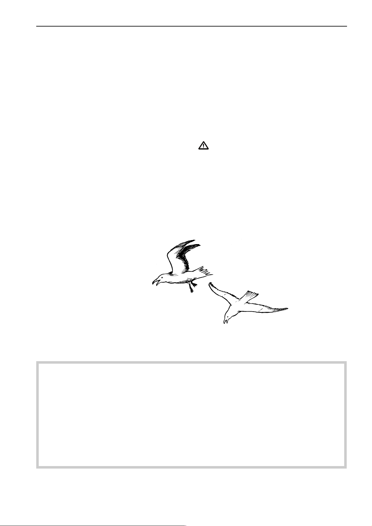
Adapt speed and distance to avoid wash and noise
disturbing or injuring animal life, moored boats, jetties, etc. Leave islands and harbours in the same
condition as you want to find them. Remember to
7742957 - Downloaded from www.volvopenta.com 22/09/2008 11:33:23
always leave hazardous waste such as waste oil,
coolant, paint and wash residue, flat batteries, etc.,
for disposal at a destruction plant.
Our joint efforts will make a valuable contribution to
our environment.
Running-in
The engine must be run in for its first 10 operating
hours as follows:
Operate the engine normally. Do not operate it at full
load except for short periods. Never run the engine at
a constant engine speed for long periods during the
running-in period.
Service and replacement parts
Volvo Penta marine engines are designed for high
operational reliability and long service life. They are
constructed to withstand the marine environment while
also affecting it as little as possible. Through regular
service and the use of Volvo Penta original spare
parts, these qualities will be retained.
The Volvo Penta worldwide network of authorized
dealers are at your service. They are specialists in
Volvo Penta products and have accessories and the
original replacement parts, test equipment and special
tools necessary for high quality service and repair
work.
Always follow the maintenance intervals contained in
the Operator's Manual. Remember to state the engine/
transmission identification number when ordering
service and replacement parts.
8
Certified engines
It is important to be aware of the following information
if you own or run an engine that is exhaust emission
certified:
Introduction
● The engine must not be modified in any way
except with accessories and service kits approved
by Volvo Penta.
Certification means that an engine type is inspected
and approved by the authorities. The engine manufacturer guarantees that all engines manufactured of that
type correspond to the certified engine.
This places special requirements for maintenance
and service as follows:
● The maintenance and service intervals recom-
mended by Volvo Penta must be observed.
● Only genuine Volvo Penta replacement parts may
be used.
● The service of injection pumps and injectors or
pump settings must always be carried out by an
authorized Volvo Penta workshop.
● No modifications to the exhaust pipes and air
supply ducts for the engine may be undertaken.
● Seals may only be broken by authorized person-
nel.
Otherwise the general instructions contained in the
Operator's Manual concerning operation, service and
maintenance must be followed.
IMPORTANT! Late or inadequate maintenance/
service or the use of spare parts other than
Volvo Penta original spare parts will invalidate
AB Volvo Penta’s responsibility for the engine
specification being in accordance with the
certificated variant.
Volvo Penta accepts no responsibility or liability
for any damage or costs arising due to the
above.
7742957 - Downloaded from www.volvopenta.com 22/09/2008 11:33:23
Warranty
Your new Volvo Penta marine engine is covered by a limited warranty according to the conditions and
instructions contained in the Warranty and Service book.
Note that AB Volvo Penta’s liability is limited to that contained in the Warranty and Service Book. Read this
book as soon as you take delivery of the engine. It contains important information about warranty cards,
service and maintenance which you, the owner, must be aware of, check and carry out. Liability covered in
the warranty may otherwise be refused by AB Volvo Penta.
Contact your Volvo Penta dealer if you have not received a Warranty and Service Book and a
customer copy of the warranty card.
9
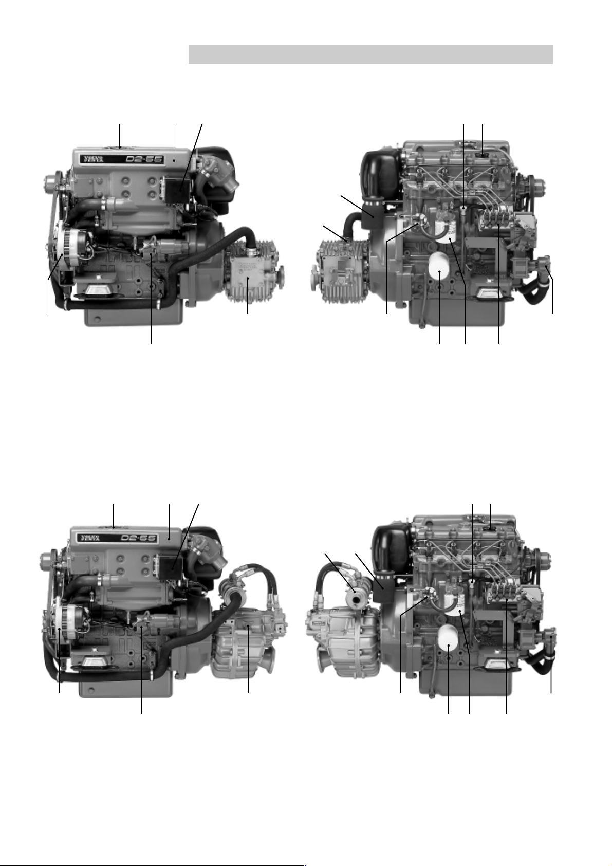
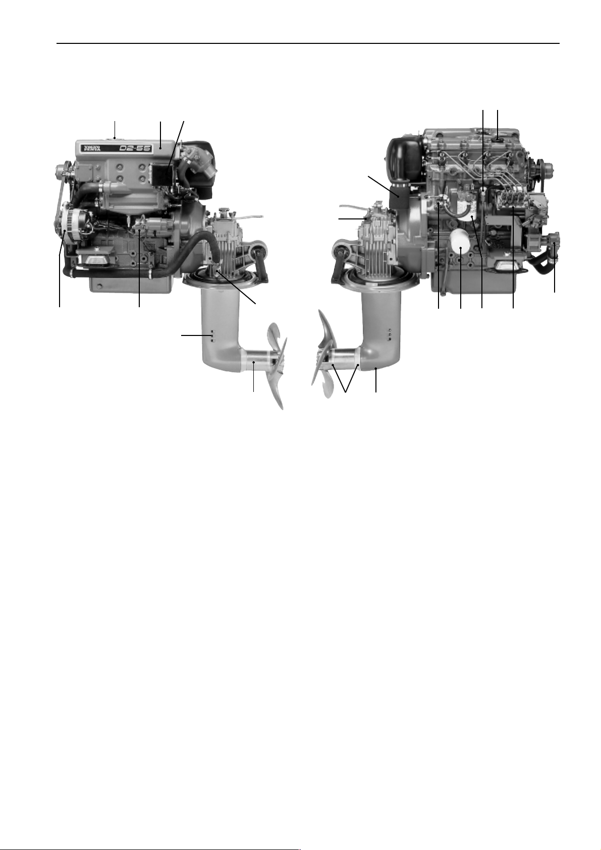
Presentation
4
1
5
D2-55 with reverse gear MS25L
3 2
8
7
6 11
D2-55 with reverse gear MS25L
10 9
15
13 12
14
1
7742957 - Downloaded from www.volvopenta.com 22/09/2008 11:33:23
4
5
D2-55 with reverse gear HS25A
9 2 3
10
6
8
7
11
13
12
D2-55 with reverse gear HS25A
14
15
10
1 3
2
7
8
9
10
Presentation
4
5
16
D2-55 with sailing boat drive MS25S
7742957 - Downloaded from www.volvopenta.com 22/09/2008 11:33:23
18
17
12
11
19 20
D2-55 with sailing boat drive MS25S
15
13 14
1. Coolant filler cap
2. Heat exchanger
3. Relay box with fuses
4. Generator
5. Starter motor
6. Oil cooler, reverse gear
7. Dipstick, reverse gear/S-drive
8. Air cleaner (ACL)/Air intake
9. Dipstick, engine
10. Oil filler cap, engine
11. Fuel pump
12. Oil filter
13. Fuel filter
14. Injection pump
15. Seawater pump
16. Cooling water intake, S-drive
17. Sea cock, S-drive
18. Folding propeller
19. Sacrificial anodes
20. Oil drain plug, S-drive
11
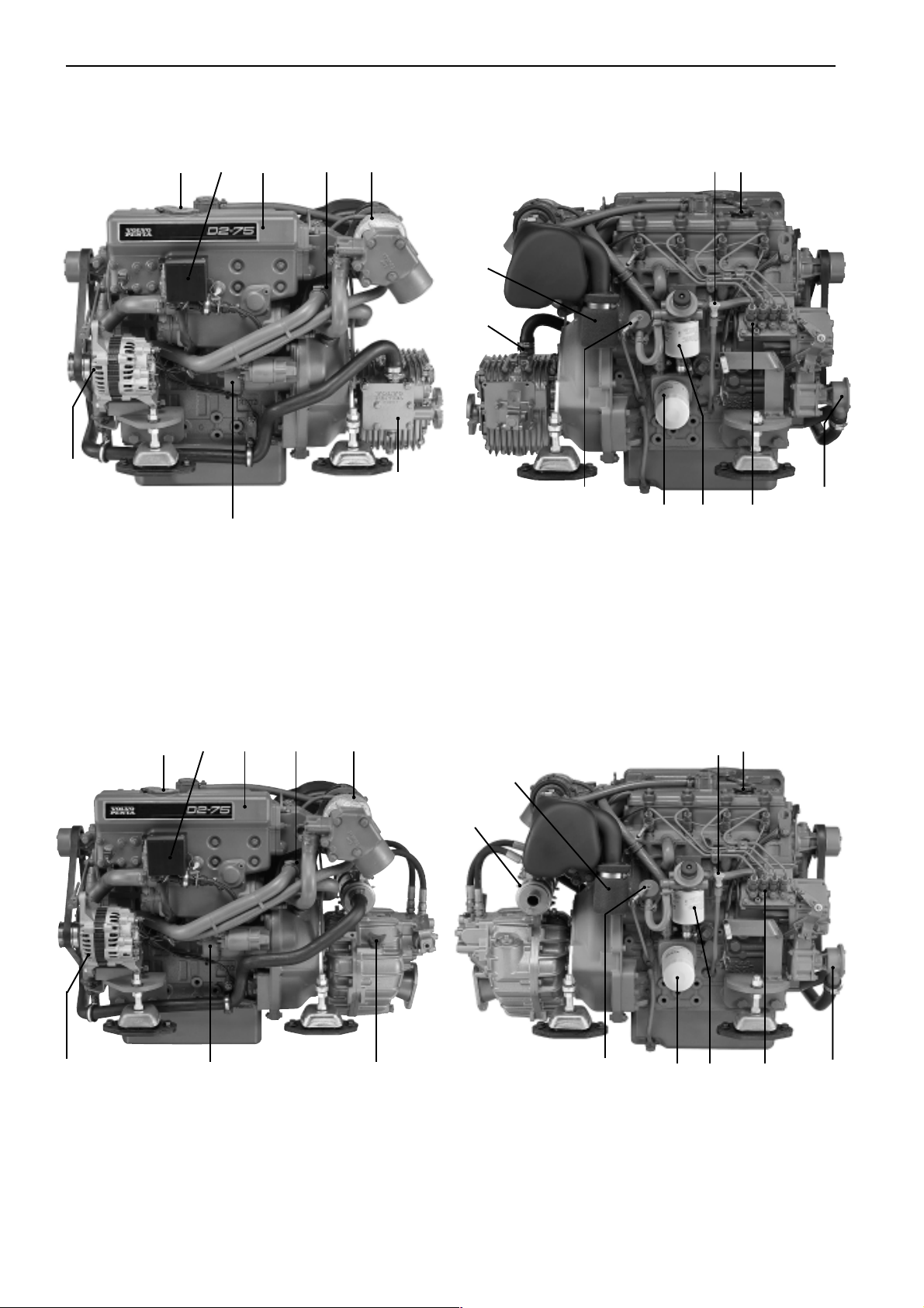
Presentation
8
23
1
4
7
D2-75 with reverse gear MS25L
5
12 11
10
9
6
13
15 14
16
17
D2-75 with reverse gear MS25L
23
1
7742957 - Downloaded from www.volvopenta.com 22/09/2008 11:33:23
8
7
4
D2-75 with reverse gear HS25A D2-75 with reverse gear HS25A
5
11
12
10
6
9
13 14
15
16
17
12
Presentation
8
23
1
7
19
18
5
4
11
12
10
9
13
14
15
16
17
20
21 22
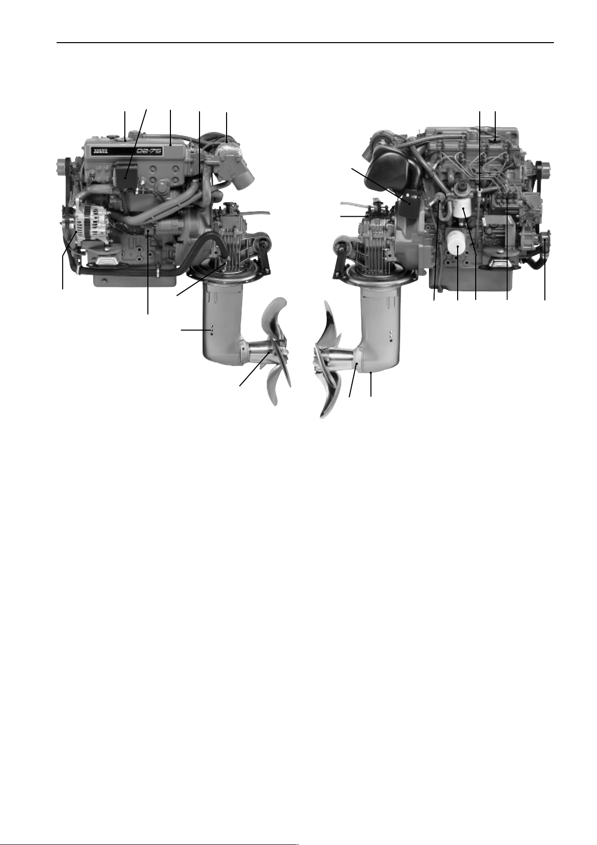
D2-75 with sailing boat drive 150S
7742957 - Downloaded from www.volvopenta.com 22/09/2008 11:33:23
1. Coolant filler cap
2. Relay box with fuses
3. Heat exchanger
4. Charge air cooler
5. Turbo
6. Oil cooler, reverse gear
7. Starter motor
8. Generator
9. Dipstick, reverse gear/S-drive
10. Air cleaner (ACL)/Air intake
11. Dipstick, engine
12. Oil filler cap, engine
13. Fuel pump
14. Oil filter
D2-75 with sailing boat drive 150S
15. Fuel filter
16. Injection pump
17. Seawater pump
18. Cooling water intake, S-drive
19. Sea cock, S-drive
20. Folding propeller
21. Sacrificial anodes
22. Oil drain plug, S-drive
13
Presentation
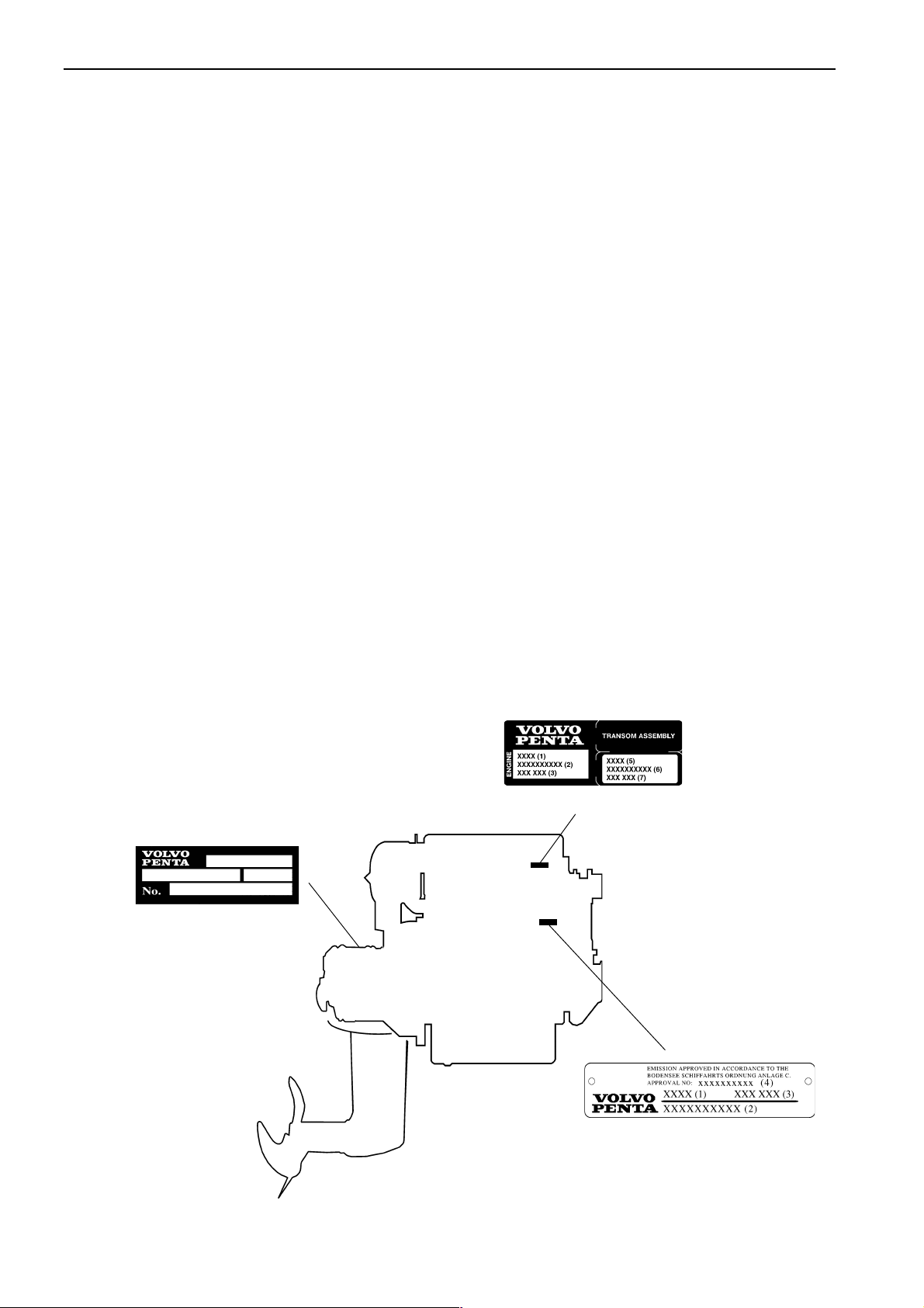
Identification number
Your engine and transmission has identification plates with identification numbers. This information should always
be quoted when ordering service and replacement parts. There are probably similar plates on your boat and its
equipment. Make a note of the details below, make a copy of the page and keep it so that you have a copy
should the boat be stolen.
The appearance and location of identification plates is shown below. The figures in brackets refer to the location
of the identification numbers on the identification plate.
Engine
Product designation (1) .......................................................................................................
Serial number (2) .................................................................................................................
Product number (3) .............................................................................................................
Certification number (4) .......................................................................................................
S-drive/Reverse gear
Product designation (5) ........................................................................................................
Serial number (6) ..................................................................................................................
Product number (7) ..............................................................................................................
Gear ratio (8) ........................................................................................................................
Propeller designation ............................................................................................................
7742957 - Downloaded from www.volvopenta.com 22/09/2008 11:33:23
XXX (5)
S-drive and reverse gear
XXXXXX (7)
XX (8)
XXXXXXXXXX (6)
Engine and transmission decal
14
Engine plate
Instrumentation
This chapter only describes the instrument panels available as standard alternatives for your engine from Volvo
Penta. Note that in certain boats instruments, alarm panels, key switches etc. may be installed separately
without the instrument panels shown here.
If you want to install additional instrumentation, or your boat is equipped with instruments not described here,
please contact your Volvo Penta dealer.
6738
15249
152
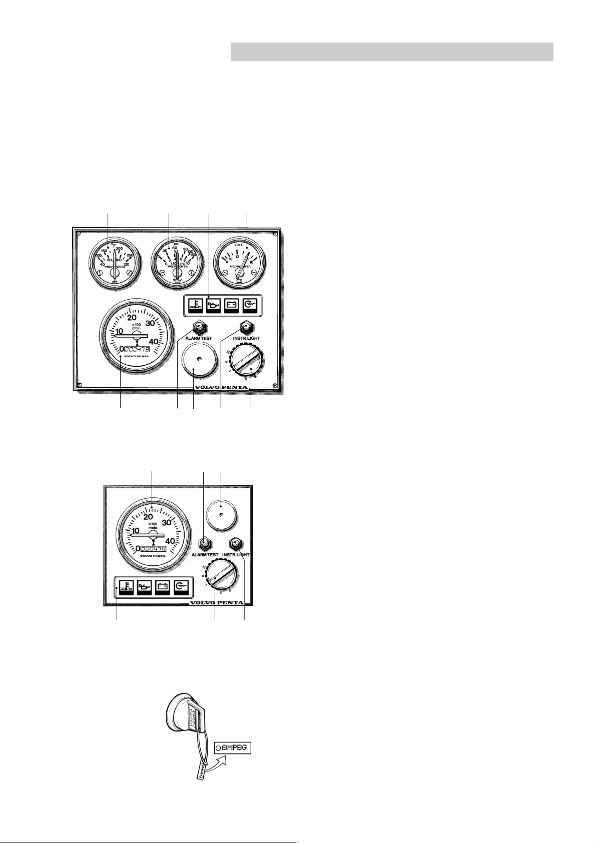
Instrument panel with ignition switch
1. Tachometer and hour counter (accessory). Displays engine speed. Multiply this value by 100 for
revolutions per minute. The hour counter displays
engine operating time in hours and tenths of an
hour.
2. Siren for acoustic alarm.
3. Warning display. See pos. 22-25.
4. Switch for instrument lighting.
5. Alarm test/acknowledgment switch.
To test alarm: Press the switch. All warning lights
light and the acoustic alarm sounds.
Alarm acknowledgment: Press the switch if there
is an alarm. The acoustic alarm stops but the
relevant warning lamp continues to flash until the
malfunction is corrected.
6. Temperature gauge. Displays the engine coolant
temperature.
7. Oil pressure gauge. Displays the oil pressure in the
engine.
7742957 - Downloaded from www.volvopenta.com 22/09/2008 11:33:23
394
8. Voltmeter. Displays the charge voltage from the
generator.
9. Ignition switch. See description in the next chapter.
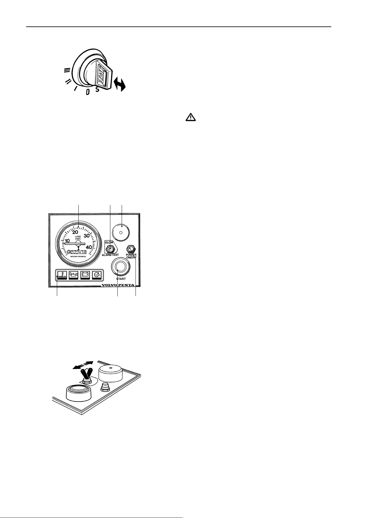
Ignition switch
The starter keys are tagged with a key code. This
code must be quoted when ordering extra keys. Keep
the code where it is not available to unauthorized
persons.
15
Instrumentation
S = The mechanical restart inhibitor is disengaged.
The key springs back automatically to the 0
position.
0 = The key can be inserted and removed.
I = Operating position.
II = Glow plug position. The glow plugs are connected
and pre-heating the engine.
III = Start position. The starter motor is engaged.
IMPORTANT! Read the starting instructions in
the chapter: Starting the engine.
10 15 11
12 14 13
7742957 - Downloaded from www.volvopenta.com 22/09/2008 11:33:23
Instrument panel without ignition switch
The instrument panel does not have an ignition
switch. To stop unauthorized persons starting the
engine the wheelhouse should have a lock or a
lockable main switch should be used.
10. Tachometer and hour counter (accessory).
Displays engine speed. Multiply this value by 100
for revolutions per minute. The hour counter
displays engine operating time in hours and
tenths of an hour.
11. Siren for acoustic alarm.
12. Warning display. See pos. 22-25.
13. Switch for connecting and disconnecting instrument panel.
14. Starter button. The starter motor is engaged when
this button is pressed.
15. Alarm test/acknowledgment and glow plug rocker
switch.
Glow plugs active: When the rocker switch is in
the up position the glow plugs are activated.
To test alarm: Move the rocker switch down. All
warning lights light and the acoustic alarm
sounds.
Alarm acknowledgment: If there is an alarm the
rocker switch is moved down and the alarm is
acknowledged. The acoustic alarm stops but the
relevant warning lamp continues to flash until the
malfunction is corrected.
16
Instrumentation
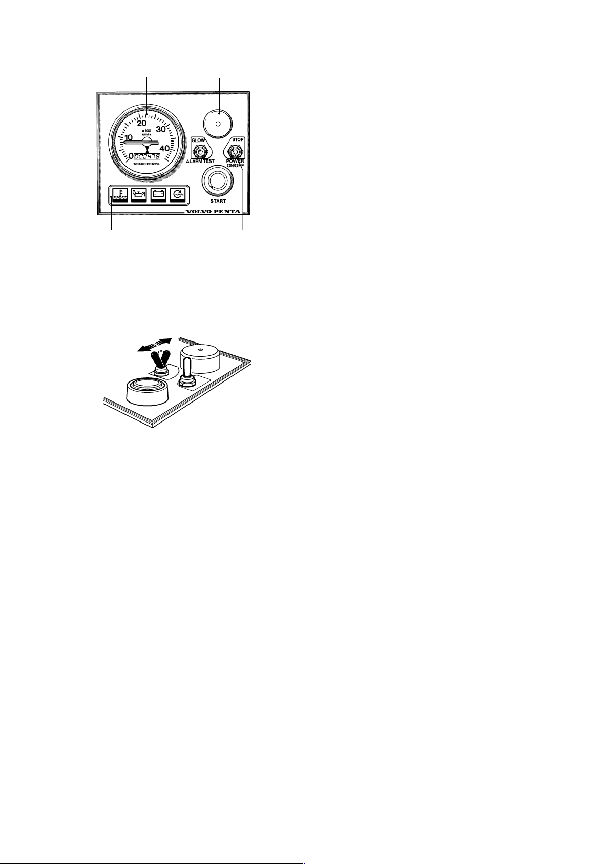
16 21 17
18 20 19
Instrument panel with electrical start/stop
function
The instrument panel does not have an ignition
switch. To stop unauthorized persons starting the
engine the wheelhouse should have a lock or a
lockable main switch should be used.
16. Tachometer and hour counter (accessory).
Displays engine speed. Multiply this value by 100
for revolutions per minute. The hour counter
displays engine operating time in hours and
tenths of an hour.
17. Siren for acoustic alarm.
18. Warning display. See pos. 22-25.
19. Rocker switch for connecting/disconnecting the
instrument panel and stop function.
20. Starter button. The starter motor is engaged when
this button is pressed.
21. Alarm test/acknowledgment and glow plug rocker
switch.
Glow plugs active: When the rocker switch is in
the up position the glow plugs are activated.
To test alarm: Move the rocker switch down. All
warning lights light and the acoustic alarm
sounds.
Alarm acknowledgment: If there is an alarm the
rocker switch is moved down and the alarm is
acknowledged. The acoustic alarm stops but the
relevant warning lamp continues to flash until the
malfunction is corrected.
7742957 - Downloaded from www.volvopenta.com 22/09/2008 11:33:23
17
Instrumentation
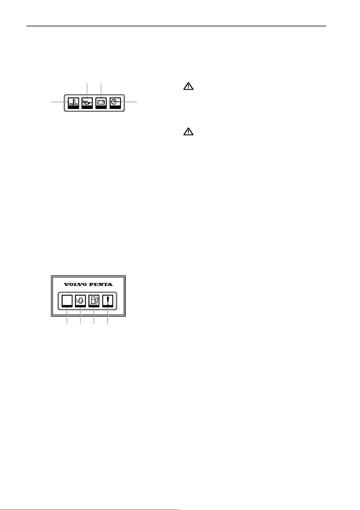
Warning display
If the acoustic alarm sounds, one of the three warning
lamps (16-18) on the instrument panel starts to flash
to indicate the source of the alarm.
23 24
22 25
22. Engine coolant temperature too high.
IMPORTANT! If the alarm sounds: Reduce engine
speed to idle (neutral). Stop the engine if the
temperature does not drop. Investigate and correct
the malfunction.
23. Low oil pressure.
IMPORTANT! If the alarm sounds: Stop the
engine immediately and investigate.
24. Generator not charging.
25. Indicator lamp Comes on when the glow plugs are
activated.
Check that the warning lamps are operating before
starting the engine according to the description of the
relevant instrument panel.
7742957 - Downloaded from www.volvopenta.com 22/09/2008 11:33:23
26 27 28 29
Extra warning display
If the acoustic alarm sounds, one of the four warning
lamps starts to flash to indicate the source of the
alarm. The extra warning display is an accessory.
26. Not used.
27. Low coolant level. Top up to correct level before
starting.
28. Water in extra fuel pre-filter. Drain off water in
filter. See instructions in the chapter Maintenance.
29. Extra alarm for an optional function.
18
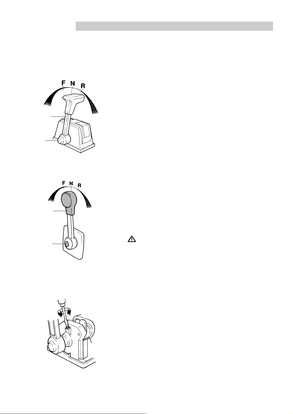
Controls
The shift function and engine speed control are combined in one lever. If necessary the shift function can be
easily disengaged so that only the engine speed (rpm) is affected by the lever. The control lever has an adjustable
friction brake. A neutral position switch is available as an accessory, this will only permit the engine to be started
with the drive/reverse gear disengaged.
Maneuvering
T
T
1
2
For top-mounted controls
Shifting and engine speed are controlled with the same lever (1).
N = Neutral position. Drive/reverse gear disengaged.
F = Drive/reverse gear engaged for movement ahead.
R = Drive/reverse gear engaged for movement astern.
T = Engine speed control
T
T
1
2
7742957 - Downloaded from www.volvopenta.com 22/09/2008 11:33:23
For side-mounted controls
Disengaging the shift function
● Move lever (1) to the neutral position (N).
● Press in button (2), move the lever slightly forward and release
the button.
The shift function is now disengaged and the lever affects only
engine speed. When the lever is moved back to the neutral
position it will automatically re-engage.
IMPORTANT! Take care not to engage the drive/reverse gear
by mistake.
Adjusting the friction brake
The friction brake only affects the engine speed control movements.
● Lift the cover over the control. For side-mounted controls the
lever must first be removed.
● Set the lever to the half-open throttle/reverse position.
● Adjust the friction brake. Turning the screw clockwise (+) makes
the lever movement stiffer, while turning counterclockwise (–)
makes it easier to move the lever.
● Reinstall the cover and lever.
19
 Loading...