

Page 1

VC820/VC840 OPERATING MANUAL
Table of Contents
Title Page
Overview
Unpacking Inspection
Safety Information
Rules For Safe Operation
Electrical Symbols
Functional Structure
Rotary Switch
Functional Buttons
Display Symbols
Manual Ranging and Autoranging
Measurement Operation
A. DC Voltage Measurement
B. AC Voltage Measurement
C. Measuring Resistance
D. Testing for Continuity
E. Testing Diode
F. Capacitance Measurement
G. Frequency or Duty Cycle Measurement
H. Temperature Measurement
I. DC or AC Current Measurement
Operation of Hold Mode
The Use of Relative Value Mode
POWER Button
1
Page 2

VC820/VC840 OPERATING MANUAL
SELECT Button (blue)
General Specification
Accuracy Specification
A. DC Voltage
B. AC Voltage
C. Resistance
D. Continuity Test
E. Diode Test
F. Capacitance
G. Frequency & Duty Cycle
H. Temperature
I. DC Current
J. AC Current
Maintenance
A. General Maintenance & Service
B. Testing the Fuses
C. Replacing the Battery
D. Replacing the Fuses
RS232C Serial Port
A. Connect with com puter
B. RS232C Port Cable
C. Setting of RS232C Serial Ports
D. System Requirements for Computer Interface Software
2
Page 3

VC820/VC840 OPERATING MANUAL
Overview
This Operating Manual covers information on safety and cautions. Please read the relevant information carefully and
observe all the warnings and notes strictly.
Warning
Read the Rules for Safety Operation carefully before using the Meter
Digital Multimeter Model VC820 and VC840 (hereafter referred to as “the Meter”) has autorange and manual range options
with maximum reading 3999. The enclosure structure design adopted advanced “co-injection” technique in order to provide
sufficient insulation.
In addition to the conventional measuring functions, there is a RS232C standard serial port is equipped with th is Meter for
easy connection with computer to realize macro recording and monitoring and capture of transient dynamic data, displaying
change of waveform during the measurement, providing data and evidence to engineering technicians for scientific research.
This is also a highly applied digital multimeter of high performance with full input protection. VC840 also has true rms
reading for AC voltage and AC current measurements.
Except where noted, the descriptions and instructions in this Operating Manual apply to both the VC820 and VC840.
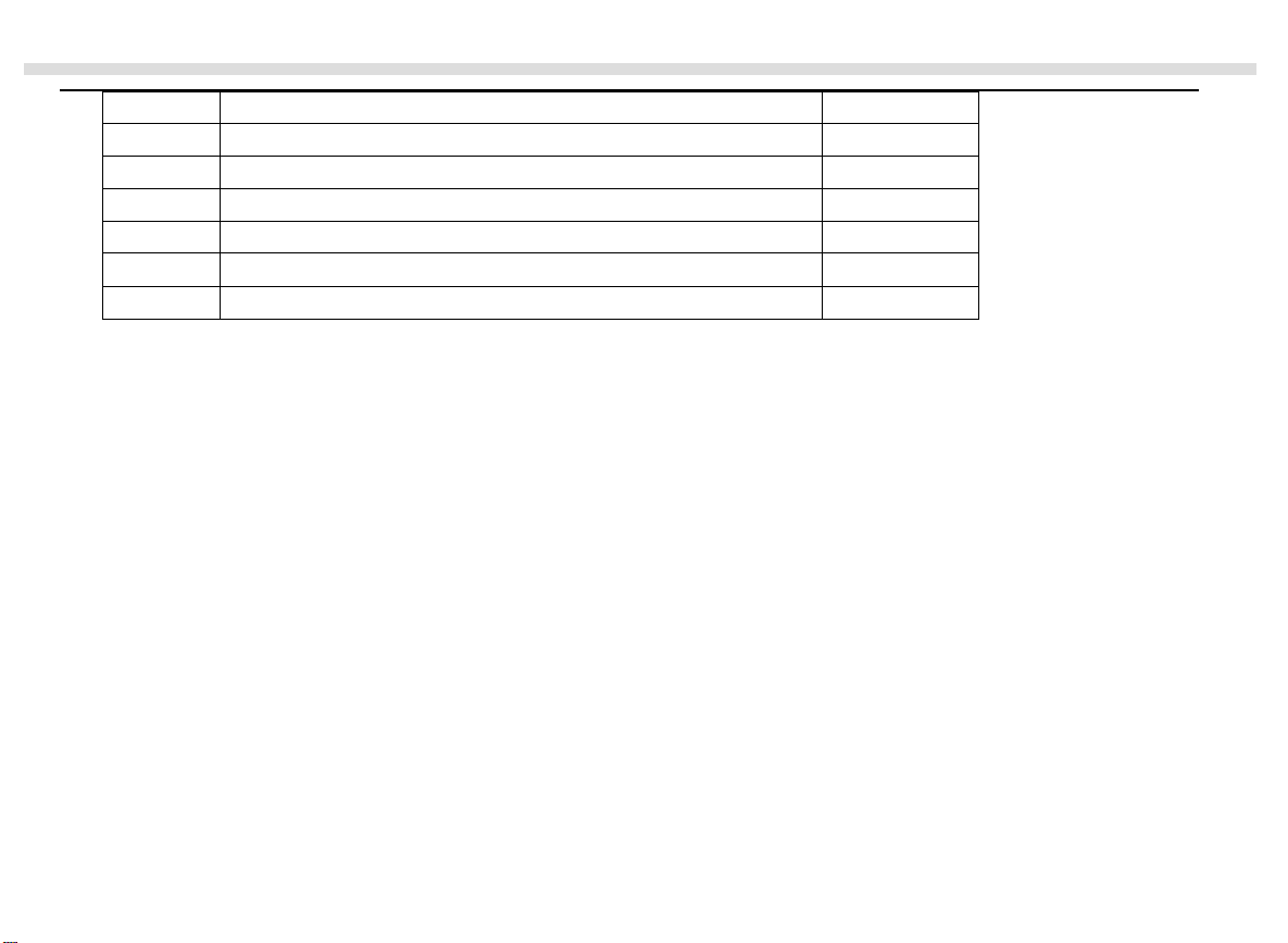
Unpacking Inspection
Open the package case and take out the Meter. Check the following items carefully to see any missing or damaged part:
3
Page 4
VC820/VC840 OPERATING MANUAL
Item Description Qty
1 Operating Manual 1 piece
2 Test Lead 1 pair
3RS232C (I) Interface cable 1 piece
4 Installation Guide & Software (CD-ROM) 1 piece
5
6 Temperature Probe (VC840 ONLY) 1 piece
In the event you find any missing or damage, please contact your dealer immediately.
Test Clip
1 piece
Safety Information
In this manual, a War n i n g identifies cond itions and actions that pose hazards to the user, or may damage the Meter or the
equipment under test.
This Meter complies with the standards GB4793.1 & IEC1010-1: In pollution degree 2, overvoltage category (CAT II
1000V, CAT III 600V) and double insulation.
CAT II: local classification of CAT II electronic equipment, portable units. Its transient overvoltage shall be less than that of
CAT III.
CAT III: Distribution level, fixed installation, with smaller transient overvoltage than CAT IV
Rules For Safe Operation
4
Page 5
VC820/VC840 OPERATING MANUAL
To avoid possible electric shock or personal injury, and to avoid possible damage to the Meter or to the equipment under
test, adhere to the following rules:
1. Do not use this Meter in the event you find the test lead, LCD display, or insulation of the case is/are obviously
broken, or you believe this Meter being malfunctioned.
2. If the test lead is/are damaged, replace new test lead with same model no. or identical electrical specifications.
3. When using the test leads, keep your fingers behind the finger guards.
4. Do not impose any effective voltage over 1000V on the terminal and earth of the Meter to prevent electric shock and
damage to the Meter.
5. When the Meter working at an effective voltage over 60V in DC or 30V in AC, special care should be taken for there is
danger of electric shock.
6. Do not operate the Meter with the case (or part of the case) removed; there is danger of electric shock.
7. When replacing fuse or battery, the test leads should be disconnected from the tested circuit and the POWER should be
pressed off before opening the case.
8. Identical nominal fuse of quick response must be used for replacement of a broken fuse.
9. The rotary switch should be placed in the right position and no any changeover of range shall be made during
measurement is conducted to prevent damage of the Meter.
10. The internal circuit of the Meter shall not be altered at will to avoid damage of the Meter and any accident.
11. Replace the battery as soon as the battery indicator
appears. With a low battery, the Meter might produce false
readings that can lead to electric shock and personal injury.
12. Soft cloth and neutral detergent should be used to clean the surface of the Meter when servicing. No abrasive and
solvent should be used to prevent the surface of the Meter from corrosion, damage and accident.
13. Do not use the Meter in an environment of high temperature, humidity, and storage of explosive or inflammable
materials. Particularly not to put the Meter in a humid condition for storage. The performance of the Meter may
deteriorate after dampened.
14. Use the proper terminals, function, and range for your measurements.
5
Page 6
VC820/VC840 OPERATING MANUAL
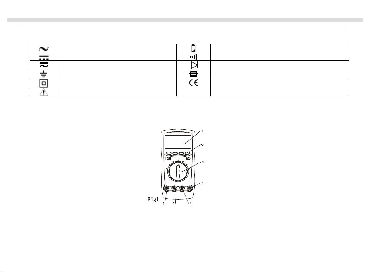
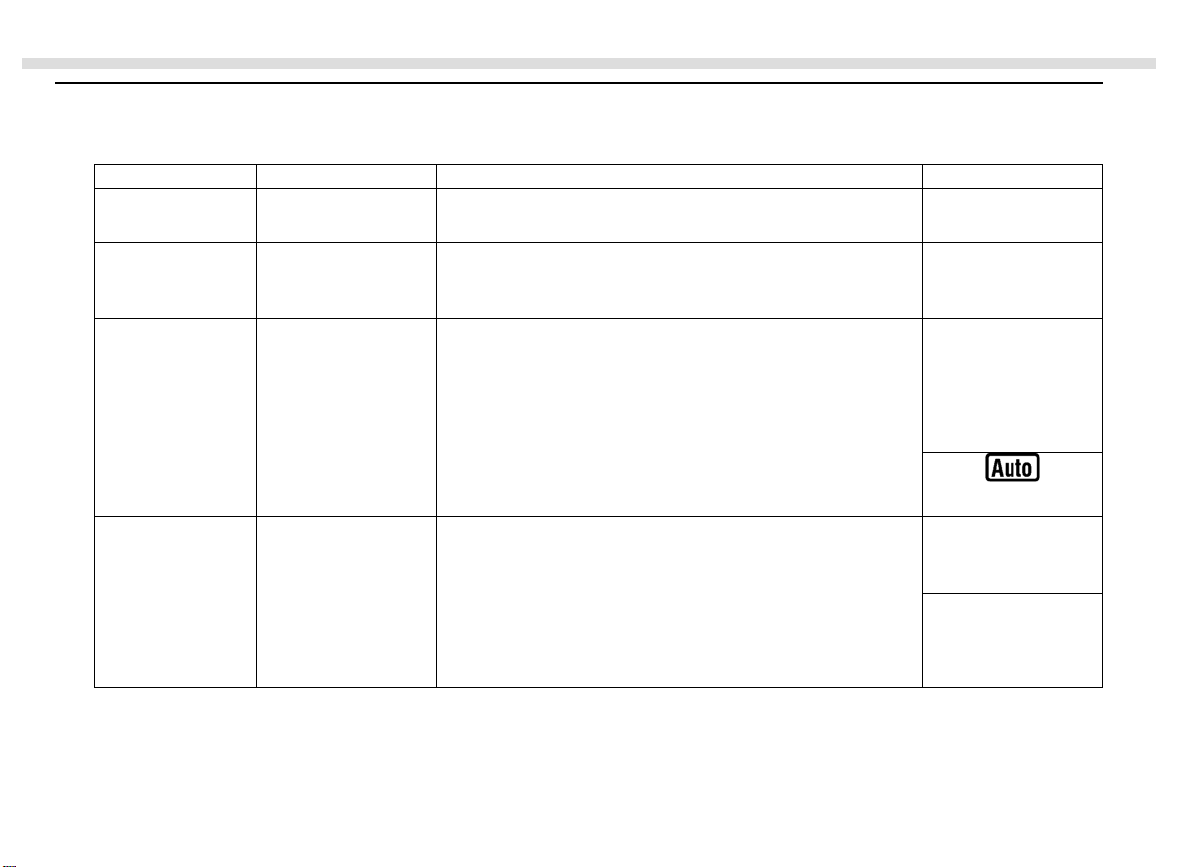
Electrical Symbols
AC (Alternating Current) Deficiency of Built-In Battery
DC (Direct Current) Continuity Test
AC or DC Diode
Grounding Fuse
Double Insulated Conforms to Standards of European Union
Warning
Functional Structure (see figure 1)
LCD Display
6
Page 7
VC820/VC840 OPERATING MANUAL
Functional Button
Rotary Switch
HzVΩ Input Terminal:
Insert the red test lead for testing voltage, frequency/duty cycle, resistance, diode, continuity and capacitance.
COM Terminal:
Insert black test lead.
µAmA Input Terminal: (VC820 ONLY)
Insert red test lead for testing current µA
0
µAmA
C Input Terminal: (VC840 ONLY)
Insert red test lead for testing current µA or mA or temperture.
20A Input Terminal:
Insert red test lead for testing current A
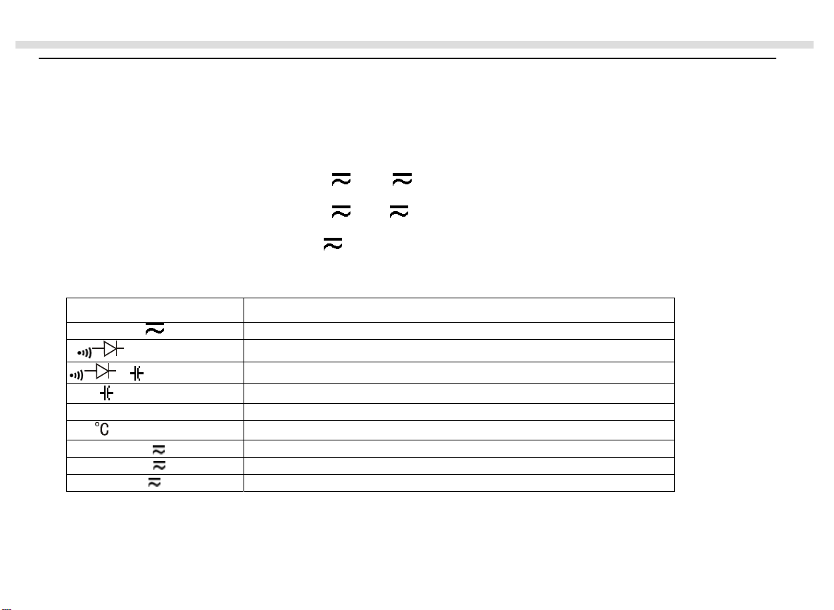
Rotary Switch
Switch Position Function
V
Ω (VC820 ONLY)
Ω (VC840 ONLY)
(VC820 ONLY)
Hz
(VC840 ONLY)
µA
mA
A
AC or DC Voltage Measurement
Continuity or Diode or Resistance Test
Continuity or Diode or Resistance or Capacitance Test
Capacitance Test
Frequency Measurement
Temperatu re in Celsius
AC or DC Current Measurement from 0.1µA to 4000µA
AC or DC Current Measurement from 0.01mA to 400.0mA
AC or DC Current Measurement from 0.001A to 20.00A
or mA .
7
Page 8
VC820/VC840 OPERATING MANUAL
y
Functional Buttons
Button Function Operation Performed LCD Displa
POWER
(the red button)
SELECT
(the blue button)
RANGE
Power Switch Turn the power on and off.
Function Selector Press SELECT to select function when there is more
Manual or Auto
Range Selection
than one function at one rotary switch po sition; the Meter
beeps.
1. Press RANGE to enter the manual ranging mode;
the Meters beeps.
Manually selecting a range causes the Meter to exit
the Hold and REL modes.
2. Press RANGE to step through the ranges available
for the selected function; the Meter beeps.
3. Press and hold RANGE for 2 seconds to return to
autoranging; the Meter beeps.
Frequency or Duty
Cycle Test
a. In frequency mode, press Hz % to toggle between
frequency measurement (Hz) and duty cycle (%)
mode; the Meter beeps.
b. In voltage or current mode, press Hz % to toggle
between voltage (V) or current (A) measurement
and frequency measurement (Hz) and duty cycle (%)
mode; the Meter beeps.
8
Hz or %Hz %
V or µA or mA or
A or Hz or %
Page 9
VC820/VC840 OPERATING MANUAL
g
play
REL
HOLD H
Relative Value
Mode
Data Holding Press HOLD to enter and exit the Hold mode in any
Press REL
mode; the Meter beeps.
mode.
to enter and exit the REL mode in any
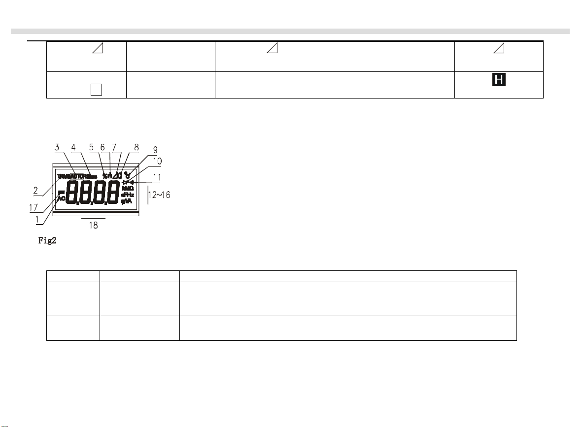
Display Symbols (see figure 2)
Number Symbol Meanin
1
2
AC
TRMS
(VC840ONLY)
Indicator for AC voltage or current.
VC820: The displayed value is the mean value.
VC840: The dis
Indicator for true rms value.
ed value is the true rms value.
9
Page 10
VC820/VC840 OPERATING MANUAL
pp
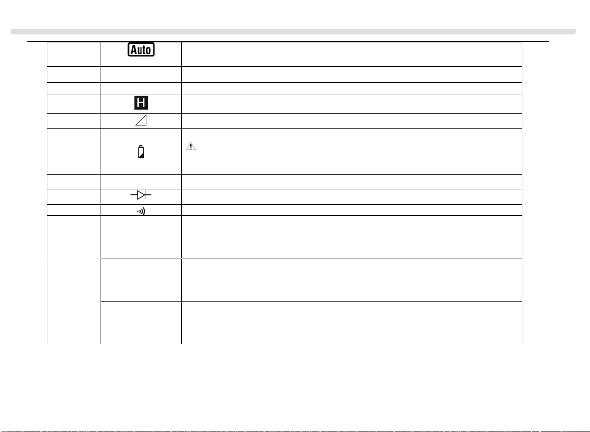
3
The Meter is in the auto range mode in which the Meter automatically selects the
range with the best resolution.
4
RS232C
Data output is in progress.
5 % Indicator for duty cycle.
6 Data hold is active.
7 The relative value mode is on to display the stored value minus the present value.
8 The battery is low.
Warning: To avoid false readings, which could lead to possible electric
shock or personal injury, replace the battery as soon as the battery indicator
a
9
0
C
ears.
Centigrade. The unit of temperature.
10 Test of diode
11 The continuity buzzer is on.
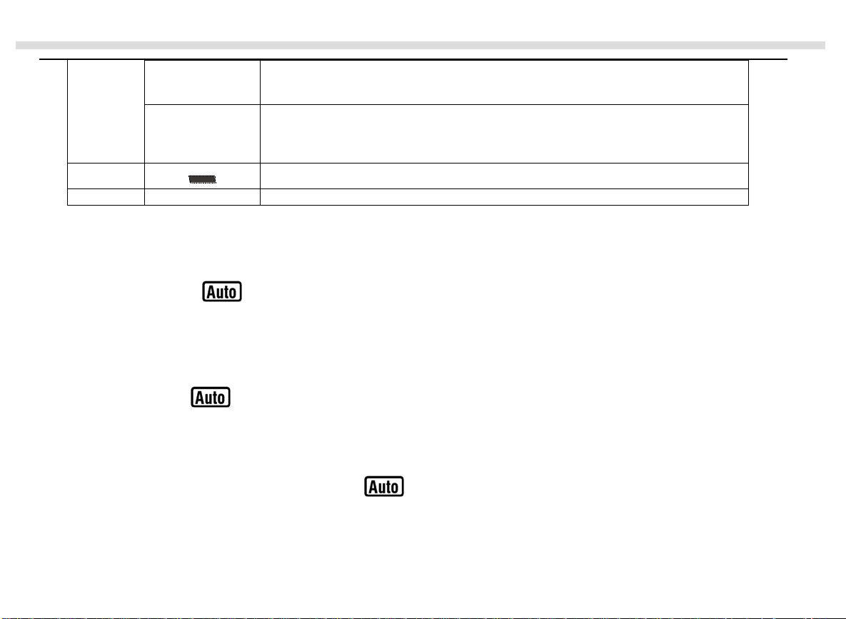
12~16
Ω,kΩ,MΩ
Ω:
kΩ:
MΩ:
Ohm. The unit of resistance.
kilohm. 1 x 10
Megohm. 1 x 10
3
or 1000 ohms.
6
or 1,000,000 ohms.
µF, nF
Hz, kHz, MHz
F:
µF:
nF:
Hz:
kHz:
MHz:
Farad. The unit of capacitance.
Microfarad. 1 x 10
Nanofarad. 1 x 10
Hertz. The unit of frequency.
Kilohertz. 1 x 10
Meghertz. 1 x 10
-6
or 0.000001 farads.
-9
or 0.000000001 farads.
3
or 1000 hertz.
6
or1,000,000 hertz.
10
Page 11
VC820/VC840 OPERATING MANUAL
V, mV
V:
mV
Volts. The unit of voltage.
Millivolt. 1 x 10
-3
or 0.001 volts.
A, mA, µA
A:
mA:
µA:
Amperes (amps). The unit of current.
Milliamp. 1 x 10
Microamp. 1x 10
-3
or 0.001 amperes.
-6
or 0.000001 amperes.
17 Indicates negative reading.
18
OL
The input value is too large for the selected range.
Manual Ranging and Autoranging
The Meter has both manual range and autorange options:
z In the autorange (
This allows you to switch test points without having to reset the range.
z In the manual range mode, you may select the range.
This allows you to override autorange and lock the Meter in a specific range.
The Meter defaults to the autorange mode in measurement functions that have more than one range. When the Meter is in
the autorange mode,
To enter and exit the manual range mode:
1. Press RANGE.
The Meter enters the manual range mode and
) mode, the Meter selects the best range for input signals.
is displayed.
turns off
11
Page 12
VC820/VC840 OPERATING MANUAL
Each presses of RANGE increments the range. When the highest range is reached, The Meter wraps to the lowest
range.
NOTE
If you manually change the measurement range after entering the REL or Hold recording modes, the Meter exits these
modes..
2. To exit the manual range model, press and hold RANGE for two seconds.
The Meter returns to the auto range mode and
is displayed.
Measurement Operation
A. DC Voltage Measurement
Warning
To avoid harms to you or damages to the Meter from electric shock, please do not attempt to measure voltages higher
than 1000V / 750V TRMS although readings may be obtained.
The DC Voltage ranges are: 400.0mV, 4 .000V, 40.00V, 400.0V and 1000V. To measure DC Voltage, connect the Meter as
follows:
1. Insert the red test lead into the HzV
2. Set the rotary switch to
3. Connect the test leads across with the object being measured.
V (DC measurement is default)
Ω terminal and the black test lead into the COM terminal.
12
Page 13

VC820/VC840 OPERATING MANUAL
The measured value shows on the display.
In each range, the Meter has an input impedance of 10MΩ. This loading effect can cause measurement errors in high
impedance circuits. If the circuit impedance is less than or equal to 10kΩ, the error is negligible (0.1% or less).
When DC voltage measurement has been completed, disconnect the connection between the testing leads and the circuit
under test, and remove the testing leads away from the input terminals of the Meter.
B. AC Voltage Measurement
Warning
To avoid harms to you or damages to the Meter from electric shock, please do not attempt to measure voltages
higher than 1000V / 750V TRMS although readings may be obtained.
The AC Voltage ranges are: 400.0mV, 4.000V, 40.00V, 400.0V and 750V. To measure AC Voltage, connect the Meter as
follows:
1. Insert the red test lead into the HzV
2. Set the rotary switch to
V and press SELECT (blue button) to select AC measurement.
3. Connect the test leads across with the object being measured.
The measured value shows on the display.
In each range, the Meter has an input impedance of 10MΩ. This loading effect can cause measurement errors in high
impedance circuits. If the circuit impedance is less than or equal to 10kΩ, the error is negligible (0.1% or less).
Ωterminal and the black test lead into the COM terminal.
Effective value stability period:
13
Page 14
VC820/VC840 OPERATING MANUAL
When the reading obtained is less than “100”, the effective value converter needs a longer time to become stabilize. When
there is no input voltage, the maximum reading displayed is “10”.
When AC voltage measurement has been completed, disconnect the connection between the testing leads and the circuit
under test, and remove the testing leads away from the input terminals of the Meter.
C. Measuring Resistance
Warning
To avoid damages to the Meter or to the devices under test, disconnect circuit power and discharge all the high-
voltage capacitors before measuring resistance.
The resistance ranges are: 400.0Ω, 4.000kΩ, 40.00kΩ, 400.0kΩ, 4.000MΩand 40.00MΩ. To measure resistance, connect
the Meter as follows:
1. Insert the red test lead into the HzV
2. Set the rotary switch to
Ω and press SELECT (blue button) to selectΩmeasurement mode.
Ω terminal and the black test lead into the COM terminal.
3. Connect the test leads across with the object being measured.
The measured value shows on the display.
The test leads can add 0.1
Ωto 0.2Ω of error to resistance measurement. To obtain precision readings in low-resistance
measurement, that is the range of 400.0Ω, short-circuit the input terminals beforehand, using the relative measurement
function button REL
to automatically subtract the value measured when the testing leads are short-circuited from the
reading.
The LCD displays OL indicating open-circuit for the tested resistor or the resistor value is higher than the maximum range
14
Page 15

VC820/VC840 OPERATING MANUAL
of the Meter.
When the value of shorted test lead is higher than 0.5Ω, check the test lead connection, pro per terminal, function and range
are made properly.
For high-resistance measurement (>1MΩ), it is normal that it will take several seconds to obtain a stable reading.
When resistance measurement has been completed, disconnect the connection between the testing leads and the circuit under
test, and remove the testing leads away from the input terminals of the Meter.
D. Testing for Continuity
Warning
To avoid damages to the Meter or to the devices under test, disconnect circuit power and discharge all the high-
voltage capacitors before testing for continuity.
To test fo r continuity, connect the Meter as below:
1. Insert the red test lead into the HzV
2. Set the rotary switch to
Ω and press SELECT (blue button) to select measurement mode.
3. The buzzer sounds if the resistance of a circuit under test is less than around 50Ω.
When continuity testing has been completed, disconnect the connection between the testing leads and the circuit under test,
and remove the testing leads away from the input terminals of the Meter.
Ωterminal and the black test lead into the COM terminal.
15
Page 16

VC820/VC840 OPERATING MANUAL
E. Testing Diode
Warning
To avoid possible damage to the Meter and to the device under test, disconnect circuit power and discharge all
high-voltage capacitors before testing diodes.
Use the diode test to check diodes, transistors, and other semiconductor devices. The diode test sends a current through the
semiconductor junction, then measures the voltage drop across the junction. A good silicon junction drops between 0.5V and
0.8V.
To test a diode out of a circuit, connect the Meter as follows:
1. Insert the red test lead into the HzV
2. Set the rotary switch to
Ω and press SELECT (blue button) to select measurement mode.
Ωterminal and the black test lead into the COM terminal.
3. Connect the test leads across with the object being measured.
The measured value shows on the display.
Connect the test leads to the proper terminals as said above to avoid error display. The LCD will display OL indicating opencircuit for wrong connection. The unit of diode is Volt (V), displaying the positive-connection voltage-drop value.
When diode testing has been completed, disconnect the connection between the testing leads and the circuit under test, and
remove the testing leads away from the input terminals of the Meter.
F. Capacitance Measurement
Warning
16
Page 17

VC820/VC840 OPERATING MANUAL
To avoid damage to the Meter or to the equipment under test, disconnect circuit power and discharge all highvoltage capacitors before measuring capacitance. Use the DC Voltage function to confirm that the capacitor is
discharged.
The Meter’s capacitance ranges are: 40.00nF, 400.0nF, 4.000µF, 40.00µF, and 100.0µF. To measure capacitance, connect the
Meter as follows:
1. Insert the red test lead or the red test clip into the HzV
Ω terminal and the black test lead or black test clip into the COM
terminal.
2. Set the rotary switch to
. (For VC820 switch toΩ and press SELECT to select nF measurement mode.)
3. Connect the test leads or the test clips across with the object being measured.
The measured value shows on the display.
The LCD displays OL indicating the tested capacitor is short or it exceeds the maximum range.
For testing the capacitor with polarity, connect the red clip to positive & black clip to negative.
When capacitance measurement has been completed, disconnect the connection between th e testing leads and the circuit
under test and remove the testing leads away from the input terminals of the Meter.
To minimize the effect of capacitance stored in the test leads, the test lead should be as short as possible. To measure a small
quantity of capacitance, use REL mode to remove the leads capacitance. Remaining voltage, insulated impedance, &
dielectric absorption from the capacitor may cause the measurement error.
G. Frequency or Duty cycle Measurement
17
Page 18

VC820/VC840 OPERATING MANUAL
The measurement range is from 5Hz to 10MHz. To measure frequency, connect the Meter as fo llows:
1. Insert the red test lead into the HzV
Ω terminal and the black test lead into the COM terminal.
2. Set the rotary switch to Hz.
3. Connect the test leads across with the object being measured.
The measured value shows on the display.
In frequency mode, press Hz % to toggle between frequency measurement (Hz) and duty cycle (%) mode.
In voltage or current mode, press Hz % to toggle between voltage or current, frequency measurement (Hz) and duty cycle
(%) mode.
Connect the Meter as above mentioned when carrying out duty cycle measurement. The duty cycle measurement range is:
0.1%~99.9%. The LCD displays OL indicating the inputted signal is high or low level.
When Hz or % measurement has been completed, disconnect the connection between the testing leads and the circuit under
test, and remove the testing leads away from the input terminals of the Meter.
H. Temperature Measurement (VC840 ONLY)
The measurement range is -40℃1000℃. To measure temperature, connect the Meter as follows:
1. Insert the red temperature probe into the
2. Set the rotary switch to .
3. Place the temperature probe to the object being measured.
The measured value shows on the display.
µA mA℃ terminal and the black temperature probe into the COM terminal.
18
Page 19

VC820/VC840 OPERATING MANUAL
The Meter’s LCD automatically displays the temperature value inside the Meter when there is no temperature probe
connection.
The included point contact temperature probe (Part no. 41700103) can only be used up to 230 or 446. For any
measurement higher than that, the rod type temperature probe (Part no. 41700109) must be used instead.
I. DC or AC Current Measurement
Warning
Never attempt an in-circuit current measurement where the open-circuit voltage between the circuit and ground is
greater than 600V.
If the fuse burns out during measurement, the Meter may be damaged or the operator himself may be hurt. Use
proper terminals, function, and range for the measurement. When the testing leads are connected to the current
terminals, do not parallel them across any circuit.
The current measurement has 3 measurement positions on the rotary switch:
µA has a 400.0µA and 4000µA range, with au to ranging; the mA has a 40.00mA and 400.0mA range, with auto
The
ranging; A
To measure current, do the following:
1 Turn off power to the circuit. Discharge all high-voltage capacitors.
2 VC820: Insert the red test lead into the µAmA or 20A terminal and the black test lead into th e COM terminal.
VC840: Insert the red test lead into the µAmA or 20A terminal and the black test lead into the COM terminal.
position has only a 4A and 20.00A range.
19
µA , mA and A .
Page 20

VC820/VC840 OPERATING MANUAL
Use the 20A terminal and A
3. Set the rotary switch to µA , mA , or A .
4. The Meter defaults to DC current measurement mode. To toggle between DC and AC current measurement function,
press SELECT (blue button).
VC820: AC current is displayed as an mean value (calibrated against sine wave effective value).
VC840: AC current is displayed as true rms value.
5. Break the current path to be tested. Connect the red test lead to the more positive side of the break and the black test
lead to the more negative side of the break.
6. Turn on power to the circuit.
The measured value shows on the display.
Effective value stability period:
When the reading obtained is less than “100”, the effective value converter needs a longer time to become stabilize. When
there is no input voltage, the maximum reading displayed is “10”.
For safety sake, the measuring time for high current should be less than 10 seconds for each measurement and the interval
time between 2 measurements should be greater than 15 minutes.
When current measurement has been completed, disconnect the connectio n between the testing leads and the circuit under
test, and remove the testing leads away from the input terminals of the Meter.
range if the current value to be tested is an unknown.
Operation of Hold Mode
Warning
To avoid possibility of electric shock, do not use Hold mode to determine if circuits are without power. The Hold
mode will not capture unstable or noisy readings.
20
Page 21

VC820/VC840 OPERATING MANUAL
The Hold mode is applicable to all measurement functions.
z Press HOLD H
z Press HOLD H
to enter Hold mode; the Meter beeps.
again or RANGE or Hz % or turn the rotary switch to exit Hold mode; the Meter beeps.
z In Hold mode,
z Th e Meter beeps when the selected range is overloaded or a positive result is obtained from continuity test, whether it
is under the Hold mode or not.
is displayed.
The Use of Relative Value Mode
The REL mode applies to all measurement functions except frequency and duty cycle measurement. It subtracts a stored
value from the present measurement value and displays the result.
For instance, if the stored value is 20.0V and the present measurement value is 22.0V, the reading would be 2.0V. If a new
measurement value is equal to the stored value then display 0.0V.
When REL mode is selected, the Meter will switch from Autoranging to Manual ranging except under capacitance testing
mode.
To en ter or exit REL mode:
z Use rotary switch to select the measurement function before selecting REL
manually after REL
z Press REL
as the stored value.
to enter REL mode, auto ranging turns off, and the present measurement range is locked and display “0”
is selected, the Meter exits the REL mode.
21
. If measurement function changes
Page 22

VC820/VC840 OPERATING MANUAL
z Press REL
again or turn the rotary switch to reset the stored value and exit REL mode.
Pressing HOLD in REL mode makes the Meter stop updating. Pressing HOLD H
again to resume updating.
POWER Button
The POWER button is a self-lock switch use to turn on or off the power of the Meter.
SELECT Button (blue)
The SELECT button uses for selecting the required measurement function when there is more than one function at one
position of the rotary switch.
General Specification
1. “HzVΩ”:Maximum voltage between terminal and ground is 1000Vrms.
2.
3.
4. Maximum Display : 3999, updates 3/second.
5. Temperature : Operating: 0 to +40 (32
6. Relative Humidity : ≤75% @ 0 - 30; ≤50% @ 31 - 40.
7. Altitude : Operating: 2000 m.
µAmA Input Terminal : 0.5A, 600V fast type ceramic fuse. (VC820)
µAmA Input Terminal: 0.5A, 600V fast type ceramic fuse. (VC840)
20A Input Terminal : 20A, 600V fast type ceramic fuse.
to +104 ).
Storage: -10 to +50 (14
Storage: 10000 m.
to +122).
22
Page 23

VC820/VC840 OPERATING MANUAL
8. Battery Type : One piece of 9V NEDA1604 or 6F22 or 006P.
9. Battery Deficiency : Display
10. Dimensions (HxWxL) : 177 x 85 x 40 mm.
11. Weight : Approximate 300g (battery included).
12. Certificate :
Accuracy Specification
Accuracy±a% reading + b digitsguarantee for 1 year.
Operating temperature23±5.
Relative humidity<75%.
A. DC Voltage
Range
400mV
4V
40V
400V
1000V
B. AC Voltage
Resolution
0.1mV
1mV
10mV
100mV
1V
Accuracy Input Protection Remarks
±(0.8%+3)
±(0.8%+1)
±(1%+3)
1000V DC
750V AC
Input impedance ≥10MΩ.
Range Resolution Accuracy Input Protection Remarks
23
Page 24

VC820/VC840 OPERATING MANUAL
4V
40V
400V
750V
1mV
10mV
100mV
1V
±(1%+5)
±(1.2%+5)
C. Resistance
Range
400Ω
4kΩ
40kΩ
400kΩ
4MΩ
40MΩ
Resolution
0.1Ω
1Ω
10Ω
100Ω
1kΩ
10kΩ
D Continuity Test
Range
400.0Ω 0.1Ω Approx. ≤70Ω
Resolution
Accuracy Input Protection Remarks
Input impedance ≥10MΩ.
1000V DC
750V AC
Accuracy Input Protection Remarks
±(1.2%+2)
±(1%+2)
±(1.2%+2)
±(1.5%+2)
VC820, displays effective value of sine wave (mean
value response).
VC840, displays true rms value.
Frequency response 40400Hz.
1000Vp Open circuit voltage approx. 0.45V
Buzzer beeps continuously
Open circuit voltage approx. 0.5V
1000Vp
E. Diode Test
24
Page 25

VC820/VC840 OPERATING MANUAL
Range Resolution Input Protection Remarks
Diode 1mV 1000Vp
Displays approximate forward bi as vol t age drop: 0.5V~0.8V
Open circuit voltage approximate 1.48V
F. Capacitance
Range
40nF 10pF
400nF 100pF
4µF1nF
40µF10nF
100µF 100nF ±(4%+5)
Resolution
Accuracy Input Protection Remarks
±(3%+10)
±(3%+5)
1000Vp
Measure at REL mode
G. Frequency & Duty Cycle
Range Resolution Accuracy Input Protection Remarks
Input sensitivity:
5Hz~10MHz
N/A
±(0.1%+3)
1000Vp
≤1MHz: ≤300m Vrms
>1MHz: ≤600m Vrms.
0.1%~99.9% 0.01% Reading is only for reference purpose
25
Page 26

VC820/VC840 OPERATING MANUAL
H. Temperature (VC840 ONLY)
Range
-401000 1
Resolution
1. DC Current
Range
400µA0.1µA
4000µA1µA
40mA 0.01mA
400mA
4A 0.001A
20A 0.01A
Resolution
VC820 VC840
0.1mA
J. AC Current
Range
Resolution
Accuracy
VC820 VC840
Accuracy Input Protection
-400±(3%+4)
0400±(1%+3)
4001000±(2%+10)
Accuracy
±(1%+2)
±(1.2%+3)
±(1.5%+5)
Input Protection Remarks
Ceramic Fuse 0.5A, 600V
Ceramic Fuse 20A, 600V
Input Protection Remarks
Fused 0.5A, 600V, fast type,
For continuous measurement≤10
seconds and interval not less than
15 minutes.
φ5x25mm.
26
Page 27

VC820/VC840 OPERATING MANUAL
400µA0.1µA
4000µA1µA
40mA 0.01mA
400mA 0.1mA
4A 0.001A
20A 0.01A
±(1.5%+5)
±(2%+5)
±(2.5%+5)
Ceramic Fuse 0.5A, 600V
Ceramic Fuse 20A, 600V
Frequency response 50 ~ 400Hz.
VC820: displays effective value of
sine wave (mean value response).
VC840: displays true rms value.
For continuous measurement≤10
seconds and interval not less than 15
minutes
MAINTENANCE
This section provides basic maintenance information including battery and fuse replacement instruction.
Do not attempt to repair or service your Meter unless you are qualified to do so and have the relevant calibration,
performance test, and service information.
A. General Service
Periodically wipe the case with a damp cloth and mild detergent. Do not use abrasives or solvents.
z To clean the terminals with cotton bar with detergent, as dirt or moisture in the terminals can affect readings.
z Turn off the power of the Meter when it is not in use and take out the battery when not using for a long time.
z Do not store the Meter in a place of humidity, high temperature and strong magnetic field.
B. Testing the Fuses
Warning
To avoid electrical shock or personal injury, remove the test leads and any input signals before replacing the battery
27
Page 28

VC820/VC840 OPERATING MANUAL
or fuse.
To prevent damage or injury, install ONLY replacement fuses with identical amperage, voltage, and speed ratings.
To test th e fuse:
1. Set the rotary switch to
2. Plug a test lead into the terminal HzVΩand connect the probe tip to the 20A terminal.
3. If the Meter beeps, the fuse is good.
z If the display shows O
If the Meter does not work while the fuse is all right, send it to your dealer for repair.
Ω and press SELECT (blue button) to select .
.L (overvoltage), replace the fuse.
C. Replacing the Battery (see figure 3)
28
Page 29

VC820/VC840 OPERATING MANUAL
Warning
To avoid false readings, which could lead to possible electric shock or personal injury, replace the battery as soon as
the battery indicator “
” appears.
To replace the battery:
1. Press the POWER to turn the Meter off and remove all connections from the terminals.
29
Page 30

VC820/VC840 OPERATING MANUAL
2. Remove the screw from the battery compartment, and separate the battery compartment from the case bottom.
3. Remove the battery from the battery compartment.
4. Replace the battery with a new 9V battery (NEDA1604, 6F22 or 006P)
5. Rejoin the case bottom and battery compartment, and reinstall the screw.
D. Replacing the Fuses (see figure 4)
Warning
To avoid electrical shock or arc blast, or personal injury or damage to the Meter, use specified fuses ONLY in
30
Page 31

VC820/VC840 OPERATING MANUAL
accordance with the following procedure.
To replace the Meter’s fuse:
1. Press the POWER to turn the Meter off and remove all connections from the terminals.
2. Remove the screw from the battery compartment, and separate the battery compartment from the case top.
3. Remove the 2 rubber feet and 2 screws from the case bottom, and separate the case top from the case bottom.
4. Remove the fuse by gently prying one end loose, then take out the fuse from its bracket.
5. Install ONLY replacement fuses with the identical type and specification as follows and make sure the fuse is fixed
firmly in the bracket.
Fuse 1: Ceramic fuse 0.5A, 600V, fast type,
Fuse 2: Ceramic fuse 20A, 600V, fast type,
6. Rejoin the battery compartment and the case top, and reinstall the screw.
7. Rejoin the case bottom and case top, and reinstall the 2 screws and 2 rubber feet.
Replacement of the fuses is seldom required. Burning of a fuse always results from improper operation.
φ5x20mm.
φ6x25 mm.
RS232C Serial Port (see figure 5)
31
Page 32

VC820/VC840 OPERATING MANUAL
A. Connect with computer
Connect the Meter with a computer using RS232C serial port as shown in figure5
32
Page 33

VC820/VC840 OPERATING MANUAL
B. RS232C Port Cable
The Meter Computer
D-sub
9 Pin Male
223RX
332TX
4420DTR
557GND
666DSR
774RTS
8 85 CTS
D-sub
9 Pin Female
C. Setting of RS232C Serial Ports
Default of RS232C serial port for communication is set as:
Baud Rate 2400
Start bit 1 (always 0)
Stop bit 1 (always 1)
Data bits 7
Parity Odd
D. System Requirements for Computer Interface Software
D-sub
25 Pin Female
Pin
Name
33
Page 34

VC820/VC840 OPERATING MANUAL
To use vc820_840 Interface Program, you need the following hardware and software:
z An IBM PC or equivalent computer with 80486 or higher processor and 640 x 480 pixel or better monitor.
z Microsoft Windows 95 or above.
z At least 8MB of RAM.
z At least 8MB free space in hard drive.
z Can access to a local or a network CD-ROM.
z A free serial port.
z A mouse or other pointing device supported by Windows.
Please refer to “ VC820/VC840Computer Interface Software ” for installation and operation instructions of the Interface
Software.
**END**
* This operating manual is subject to change without notice.*
Manufacturer:
Uni-Trend International Limited
Rm901, 9/F, Nanyang Plaza
57 Hung To Road, Kwun Tong
Kowloon, Hong Kong
Tel.: (852) 2950 9168
Fax.: (852) 2950 9303
Email: info@uni-trend.com
http://www.uni-trend.com
34
Page 35

VC820/VC840 Computer Interface Software
A. System Requirements
To use vc820_840 Interface Program, you need the following hardware and software:
z An IBM PC or equivalent computer with 80486 or higher processor and 640 x 480 pixel or better monitor.
z Microsoft Windows 95 or above.
z At least 8MB of RAM.
z At least 8MB free space in hard drive.
z Can access to a local or a network CD-ROM.
z A free serial port.
z A mouse or other pointing device supported by Windows.
B. Installing vc820_840 Interface Program
To in stall vc820_840 Interface Program, please follow below procedure:
Before install the interface program, make sure that the computer is running the Window 95 or above operating system.
1. -Insert the provided CD-ROM into CD-ROM drive.
-Double-click the My Computer icon from the Windows desktop.
-Locate the CD-ROM drive from the window, double-click the drive letter to display the folder of vc820_840.
-Double-click vc820_840 to display the contents of the folder.
-Double-click the file Setup.Exe.
2. Follow the on-screen installation instructions.
3. The installation program will create a vc840_840 Interface Program folder.
You will be prompted to select the kind of Program Folder you want to install; you should select “vc820_840 Interface
Program”.
C. Getting Started with vc820_840 Interface Program
1
Page 36

VC820/VC840 Computer Interface Software
To run the vc820_840 Interface Program, please do the followings:
1. Insert the supplied RS232C (I) interface cable into the slot at th e b ack of the meter and properly connect the other end of
the cable to the serial port of computer.
“NO COM” will be displayed on the computer screen if it is not connected properly.
2. From the Windows Start menu, choose Programs > vc820_840 Interface Program > vc820_840
3. Press COMSetup to select corresponding COM 1/ 2 / 3 / 4.
4. Press Connect from menu bar to start the connection, the icon
will be displayed.
D. Graphical Operations (see figure 1)
During the connection, you can select the following functions by clicking the corresponding icon:
Fill: Click the box to select “fill-up graph” or unclick to select “line graph”.
Record: Setting the number of record to show on graph.
Clear: To clear all the graphics records permanently.
Save: To save a file in BMP format. The default file name is C:\DATA1.BMP”.
First: Go to the first graphic.
Previous: Go to the previous graphic.
Next: Go to the next graphic.
Last: Go to the last graphic.
Zoom In: To enlarge part of the graphic.
2
Page 37

VC820/VC840 Computer Interface Software
Graphic Selection
No. of records setting
E. Data Recording Operations (see figure 2)
During the connection, you can select the following functions by clicking the corresponding icon:
Repeat: Click the box to keep the repeat record, or unclick the box to ignore the repeat record.
Clear
Fill-Up Graph
Save
First
Previous
Next
Last
Zoom In
(figure 1)
3
Page 38

VC820/VC840 Computer Interface Software
Sampling Interval: Click to enable sampling interval function, or unclick to disable the function
Enter the sampling interval time, the unit is second.
Clear: To clear all the records permanently.
Save: To save all the record.
Sampling interval
selecting
Keep or ignore the
repeat record
F. Max Min Operations (see figure 3)
MIN: Recorded maximum value.
Enter the time
Clear
Save
(figure 2)
4
Page 39

VC820/VC840 Computer Interface Software
MIN: Recorded minimum value.
SetMax: Click to enable the SetMax function or unclick to disable.
Enter the upper limit value in full digit, it does not identify range or function.
SetMin: Click to enable the SetMin function or unclick to disable.
Enter the lower limit value in full digit, it does not identify range or function.
The Meter is connected properly to the computer and data is recording.
OL!! Overload, the recorded value exceeds the SetMax and SetMin valu e. It will be flashing and the computer will
sound if loudspeaker is installed.
Upper limit setting
Recorded maximum value. Recorded minimum value
Connected & data recording
Red line indicates limits exceeding
Enable SetMax function
Overload
Lower limit setting
figure 3
5
Page 40

VC820/VC840 Computer Interface Software
Remarks:
1. Before you re-install the software, please remove the installed program as follows:
My Computer > Control Panel > Add/Remove Programs
2. If abnormal digits or symbols were found, please remove font ”UNIT-A2” and then install new font set from ”FONT”
directory on the provided CD-ROM.
3. No special notice or free replacement will be provided when update version is issued.
**END**
* This operating manual is subject to change without notice. *
Manufacturer:
Uni-Trend International Limited
Rm901, 9/F, Nanyang Plaza
57 Hung To Road, Kwun Tong
Kowloon
Hong Kong
Tel.: (852) 2950 9168
Fax.: (852) 2950 9303
Email: info@uni-trend.com
http://www.uni-trend.com
6
Page 41

VC820/VC840 Computer Interface Software
7
 Loading...