

쮕
BEDIENUNGSANLEITUNG
°
Version 11/08
FI-Schnelltester VC-34
Best.-Nr. 10 10 08
Bestimmungsgemäße Verwendung
Der VC-34 dient zum schnellen Funktionstest von Fehlerstrom-Schutzschaltern (übliche
Kurzbezeichnung „FI“ oder „RCD“) in elektrischen Anlagen der Überspannungskategorie CAT III
bis 250 V. Am Testgerät können über 5 Tasten unterschiedliche Fehlerströme (IΔn) simuliert
werden. Diese Fehlerströme sind ausgelegt für haushaltsübliche FI-Schutzschalter von 0,01 mA
bis hin zu speziellen FI-Schutzschaltern mit Fehlerströmen von 0,5 A. Die Auslösung wird über
eine rote Leuchtanzeige signalisiert. Die Einwirkdauer des Nenn-Fehlerstroms ist Normgerecht
und entspricht <200 ms.
Der Tester wird über die anliegende Netzspannung versorgt und benötigt keine zusätzliche
Spannungsversorgung. Der FI-Test ist deshalb nur unter Spannung möglich.
Der Tester ist kein Prüfgerät nach EN 61557 und darf nicht zur Erstprüfung elektrischer Anlagen
nach VDE 0100 Teil 600 verwendet werden.
Der Schnelltester darf im Freien und in Innenräumen eingesetzt werden (IP64).
Eine andere Verwendung als zuvor beschrieben führt zur Beschädigung dieses Produktes, darüber
hinaus ist dies mit Gefahren, wie z.B. Kurzschluss, Brand, elektrischer Schlag etc. verbunden.
Das gesamte Produkt darf nicht geändert bzw. umgebaut werden.
Der VC-34 darf im geöffneten Zustand nicht betrieben werden. Der Einsatz unter widrigen
Umgebungsbedingungen wie z.B. Staub und brennbare Gase, Dämpfe oder Lösungsmittel ist
nicht zulässig.
Die Sicherheitshinweise sind unbedingt zu beachten!
Lieferumfang
• VC-34 FI-Schnelltester
• Bedienungsanleitung
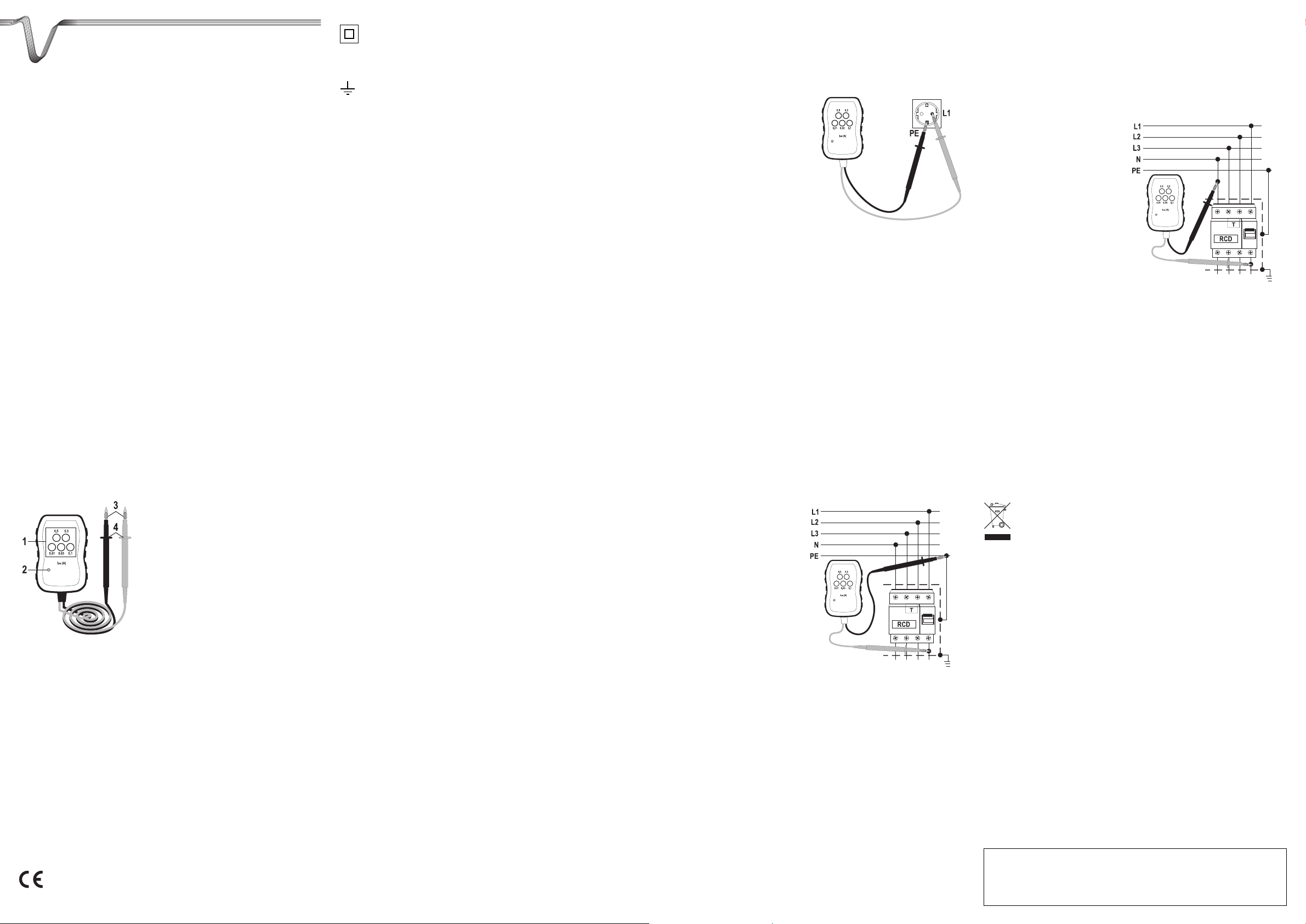
Einzelteilbezeichnung
1 Folientasten für den Nenn-Fehlerstrom
2 Rote LED-Anzeige
3 Prüfspitzen
4 Fühlbare Griffbereichsmarkierung
Sicherheitshinweise
Lesen Sie bitte vor
Inbetriebnahme die komplette
Anleitung durch, sie enthält
wichtige Hinweise zum korrek-
ten Betrieb.
Bei Schäden, die durch Nichtbeachten dieser Bedienungsanleitung verursacht werden, erlischt der Garantieanspruch! Für Folgeschäden übernehmen wir keine Haftung!
Bei Sach- oder Personenschäden, die durch unsachgemäße Handhabung
oder Nichtbeachten der Sicherheitshinweise verursacht werden, übernehmen wir keine Haftung! In solchen Fällen erlischt jeder Garantieanspruch.
Folgende Symbole gilt es zu beachten:
Ein in einem Dreieck befindliches Ausrufezeichen weist auf wichtige Hinweise in
dieser Bedienungsanleitung hin, die unbedingt zu beachten sind.
☞
Das „Hand“-Symbol ist zu finden, wenn Ihnen besondere Tipps und Hinweise zur
Bedienung gegeben werden sollen.
Dieses Gerät ist CE-konform und erfüllt somit die erforderlichen europäischen
Richtlinien.
Schutzklasse 2 (doppelte oder verstärkte Isolierung)
CAT III Überspannungskategorie III für Messungen in der Gebäudeinstallation (z.B.
Steckdosen oder Unterverteilungen).
Erdpotential
Aus Sicherheits- und Zulassungsgründen (CE) ist das eigenmächtige Umbauen und/oder
Verändern des Produkts nicht gestattet.
In gewerblichen Einrichtungen sind die Unfallverhütungsvorschriften des Verbandes der gewerblichen Berufsgenossenschaften für elektrische Anlagen und Betriebsmittel zu beachten.
In Schulen und Ausbildungseinrichtungen, Hobby- und Selbsthilfewerkstätten ist der Umgang mit
Messgeräten durch geschultes Personal verantwortlich zu überwachen.
Die Spannung zwischen dem Testgerät und Erdpotential darf 250 V in CAT III nicht überschreiten.
Seien Sie besonders Vorsichtig beim Umgang mit Spannungen >25 V Wechsel- (AC) bzw. >35
V Gleichspannung (DC)! Bereits bei diesen Spannungen können Sie bei Berührung elektrischer
Leiter einen lebensgefährlichen elektrischen Schlag erhalten.
Überprüfen Sie vor jeder Messung Ihr Gerät und deren Messleitungen auf Beschädigung(en).
Führen Sie auf keinen Fall Messungen durch, wenn die schützende Isolierung beschädigt (eingerissen, abgerissen usw.) ist.
Um einen elektrischen Schlag zu vermeiden, achten Sie darauf, dass Sie die zu messenden
Anschlüsse/Messpunkte während der Messung nicht, auch nicht indirekt, berühren. Über die
fühlbaren Griffbereichsmarkierungen an den Messspitzen darf während des Messens nicht
gegriffen werden.
Verwenden Sie das Multimeter nicht kurz vor, während oder kurz nach einem Gewitter
(Blitzschlag/energiereiche Überspannungen). Achten Sie darauf, dass ihre Hände, Schuhe,
Kleidung, der Boden, Schaltungen und Schaltungsteile usw. unbedingt trocken sind.
Das Produkt ist kein Spielzeug, es ist nicht für Kinderhände geeignet. Positionieren Sie es außerhalb der Reichweite von Kindern.
Lassen Sie das Verpackungsmaterial nicht achtlos liegen, dieses könnte für Kinder zu einem
gefährlichen Spielzeug werden.
Arbeiten Sie mit dem Gerät nicht in Räumen oder bei widrigen Umgebungsbedingungen, in/bei
welchen brennbare Gase, Dämpfe oder Stäube vorhanden sind oder vorhanden sein können.
Wenn anzunehmen ist, dass ein gefahrloser Betrieb nicht mehr möglich ist, so ist das Gerät
außer Betrieb zu setzen und gegen unbeabsichtigten Betrieb zu sichern. Es ist anzunehmen,
dass ein gefahrloser Betrieb nicht mehr möglich ist, wenn:
- das Gerät sichtbare Beschädigungen aufweist,
- das Gerät nicht mehr arbeitet und
- nach längerer Lagerung unter ungünstigen Verhältnissen oder
- nach schweren Transportbeanspruchungen.
Schalten Sie das Messgerät niemals gleich dann ein, wenn dieses von einem kalten in einen warmen Raum gebracht wird. Das dabei entstandene Kondenswasser kann unter Umständen Ihr
Gerät zerstören. Lassen Sie das Gerät uneingeschaltet auf Zimmertemperatur kommen.
Wenden Sie sich an eine Fachkraft, wenn Sie Zweifel über die Arbeitsweise, die Sicherheit oder
den Anschluss des Gerätes haben.
FI-Test durchführen
Die beiden Messspitzen sind mit fühlbaren Griffbereichsmarkierungen (4) versehen. Diese Markierungen kennzeichnen das Ende des Griffbereichs und dürfen
während der Messung nicht übergriffen werden.
Die Messleitungen dürfen nur zwischen einem Außenleiter (Phase „L“) und
Schutzleiter „PE“ bzw. Neutralleiter „N“ erfolgen. Der Anschluss zwischen zwei
Phasen (z.B. L1 und L2) ist nicht zulässig.
Allgemein
Einen Schnelltest der FI-Schutzfunktion kann an jeder installierten Schutzkontakt-Steckdose
oder direkt in der Unterverteilung am FI-Schutzschalter durchgeführt werden.
Zum Test entfernen Sie die Kunststoffschutzkappen von den Prüfspitzen (3).
Die unterschiedlichen Anschlussarten werden Ihnen in den folgenden Kapiteln erklärt.
☞
In Wohnräumen werden üblicherweise Fehlerstrom-Schutzschalter mit einem
Auslösestrom (IΔn) von 0,03A (30 mA) eingesetzt.
In gewerblichen Räumen (z.B. Werkstätten) kann dieser Wert bis zu 0,5 A betragen.
Beginnen Sie den FI-Schnelltest immer mit dem Nennfehlerstrom der am FISchutzschalter angegeben ist.
Beachten Sie, dass beim Auslösen des FI-Schutzschalters alle angeschlossenen
Installationen stromlos geschaltet werden. Dies kann bei manchen Geräten zum
Verlust von Datenspeichern etc. führen.
Beim Test darf immer nur eine Folientaste gedrückt werden. Zwischen den Tests
muss eine Pause von 10 s eingehalten werden.
Erfolgt keine Auslösung des FI-Schutzschalters beim Test mit dem
Nennfehlerstrom, so lassen Sie den FI-Schutzschalter von einer Fachkraft überprüfen.
FI-Schnelltest an Schutzkontakt-Steckdosen
Um die Funktion des Fehlerstromschutzschalters an den Steckdosen testen zu können gehen
Sie wie folgt vor:
• Kontaktieren Sie die schwarze Prüfspitze mit
dem Schutzkontakt (PE, Metallklammern)
der Steckdose.
• Stecken Sie die rote Prüfspitze in eine Öffnung
der Steckdose (L1). Die rote LED-Anzeige (2)
muss aufleuchten. Leuchtet diese nicht, so
wechseln Sie mit der roten Prüfspitze in die
andere Öffnung der Steckdose.
• Das Leuchten signalisiert die vorhandene
Netzspannung.
• Drücken Sie z.B. die Folientaste „0,01“ und
halten diese für ca. 1 Sekunde gedrückt.
Der Tester simuliert automatisch den entsprechenden Fehlerstrom mit einer Einwirkdauer von
<200 ms.
• Löst der FI-Schutzschalter aus, erlischt die rote LED-Anzeige. Bleibt die Anzeige an, reicht der
Fehlerstrom noch nicht für eine Auslösung aus. Wiederholen Sie den vorhergehenden Schritt
bis zu 3x. Erfolgt keine Auslösung, fahren Sie mit dem nächsten Schritt fort.
• Drücken Sie die nächst höhere Folientaste, z.B. „0,03“, und halten diese für ca. 1 Sekunde
gedrückt. Führen Sie diesen Testpunkt so lange fort, bis der FI-Schutzschalter auslöst.
• Entfernen Sie nach Testende alle Prüfspitzen von der Steckdose.
• Schalten Sie den ausgelösten FI-Schutzschalter nach dem Test wieder ein. Angeschlossene Kühlund Gefriersysteme werden bei abgeschaltetem FI-Schutzschalter nicht mit Strom versorgt.
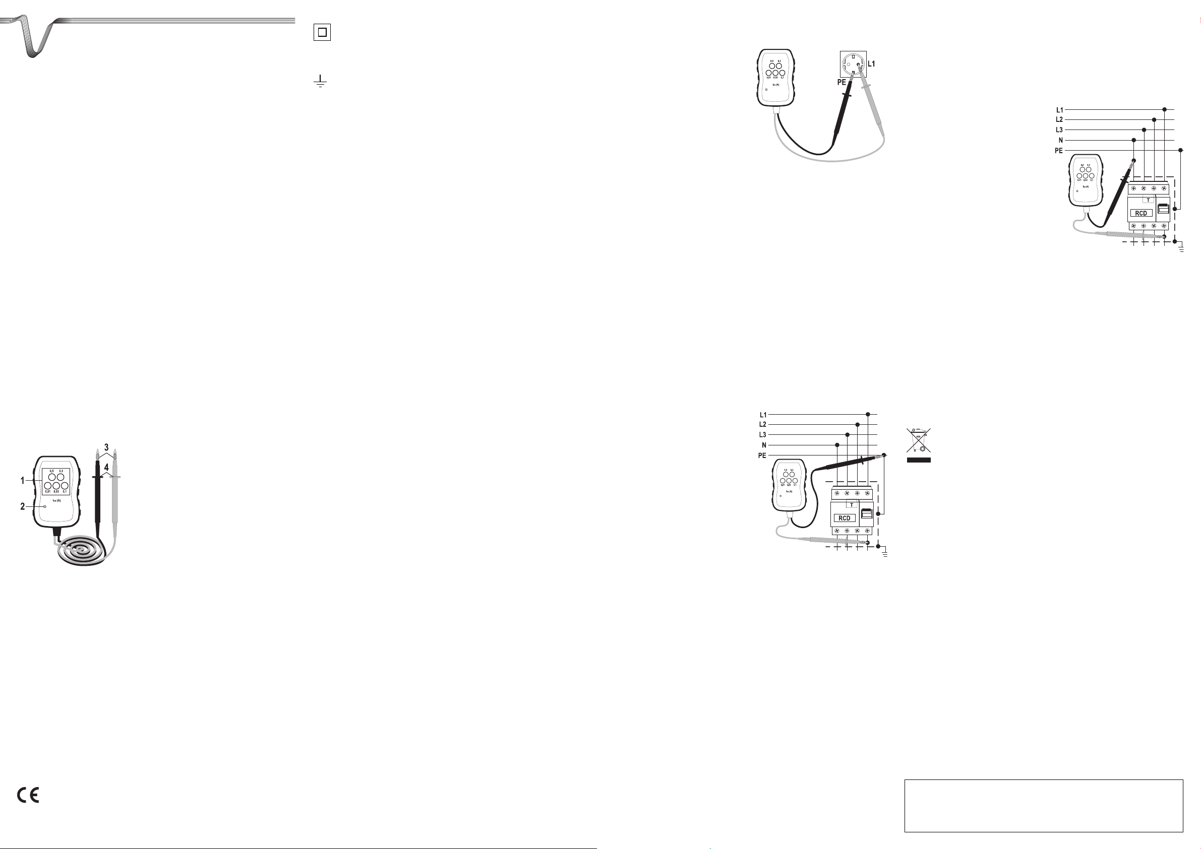
FI-Schnelltest der Installation in der Unterverteilung
Messungen in Unterverteilungen dürfen nur durch Fachpersonal durchgeführt
werden, welche mit den erforderlichen Sicherheitsvorschriften und möglichen
Gefahren vertraut ist.
Diese Funktion ermöglicht die Überprüfung von Installationen, die von Fehlerstromschutzschaltern überwacht werden (identisch mit Steckdosentest).
Um die Funktion des Fehlerstromschutzschalters in der Unterverteilung testen zu können gehen
Sie wie folgt vor:
• Nehmen Sie bei Bedarf die Kunststoffab- dekkung im Unterverteiler ab, um an die
Kontakte des FI-Schutzschalters zu gelangen.
• Kontaktieren Sie die schwarze
Prüfspitze mit dem Schutzkontakt (PESammelschiene).
• Verbinden Sie die rote Prüfspitze mit
einem am Ausgang befindlichen
Außenleiter (L1, L2 oder L3) am FISchutzschalter. Die rote LED-Anzeige
(2) muss aufleuchten.
• Das Leuchten signalisiert die vorhandene Netzspannung.
• Drücken Sie z.B. die Folientaste „0,01“ und
halten diese für ca. 1 Sekunde gedrückt.
Der Tester simuliert automatisch den
entsprechenden Fehlerstrom mit einer Einwirkdauer von <200 ms.
• Löst der FI-Schutzschalter aus, erlischt die rote LED-Anzeige. Bleibt die Anzeige an, reicht der
Fehlerstrom noch nicht für eine Auslösung aus. Wiederholen Sie ggf. den vorhergehenden
Schritt bis zu 3x. Erfolgt keine Auslösung, fahren Sie mit dem nächsten Schritt fort.
• Drücken Sie die nächst höhere Folientaste, z.B. „0,03“, und halten diese für ca. 1 Sekunde
gedrückt. Führen Sie diesen Testpunkt so lange fort, bis der FI-Schutzschalter auslöst.
• Entfernen Sie nach Testende alle Prüfspitzen aus der Unterverteilung und setzen die
Kunststoff-Abdeckungen wieder auf die Verteilung.
• Schalten Sie den ausgelösten FI-Schutzschalter nach dem Test wieder ein. Angeschlossene
Kühl- und Gefriersysteme werden bei abgeschaltetem FI-Schutzschalter nicht mit Strom versorgt.
FI-Schnelltest in der Unterverteilung
Messungen in Unterverteilungen dürfen nur durch Fachpersonal durchgeführt
werden, welche mit den erforderlichen Sicherheitsvorschriften und möglichen
Gefahren vertraut ist.
Diese Funktion ermöglicht die Überprüfung des FI-Schutzschalters selbst..
Um die Funktion des Fehlerstromschutzschalters in der Unterverteilung testen zu können gehen
Sie wie folgt vor:
• Nehmen Sie bei Bedarf die Kunststoffab- dekkung im Unterverteiler ab, um an die
Kontakte des FI-Schutzschalters zu gelangen.
• Kontaktieren Sie die schwarze
Prüfspitze mit dem Neutralleiter (N) am
Eingang des FI-Schutzschalters.
• Verbinden Sie die rote Prüfspitze mit
einem am Ausgang befindlichen
Außenleiter (L1, L2 oder L3) am FISchutzschalter. Die rote LED-Anzeige
(2) muss aufleuchten.
• Das Leuchten signalisiert die vorhandene Netzspannung.
• Drücken Sie z.B. die Folientaste „0,01“ und
halten diese für ca. 1 Sekunde gedrückt.
Der Tester simuliert automatisch den entsprechenden Fehlerstrom mit einer Einwirkdauer von
<200 ms.
• Löst der FI-Schutzschalter aus, erlischt die rote LED-Anzeige. Bleibt die Anzeige an, reicht der
Fehlerstrom noch nicht für eine Auslösung aus. Wiederholen Sie den vorhergehenden Schritt
bis zu 3x. Erfolgt keine Auslösung, fahren Sie mit dem nächsten Schritt fort.
• Drücken Sie die nächst höhere Folientaste, z.B. „0,03“, und halten diese für ca. 1 Sekunde
gedrückt. Führen Sie diesen Testpunkt so lange fort, bis der FI-Schutzschalter auslöst.
• Entfernen Sie nach Testende alle Prüfspitzen aus der Unterverteilung und setzen die
Kunststoff-Abdeckungen wieder auf die Verteilung.
• Schalten Sie den ausgelösten FI-Schutzschalter nach dem Test wieder ein. Angeschlossene
Kühl- und Gefriersysteme werden bei abgeschaltetem FI-Schutzschalter nicht mit Strom versorgt.
Entsorgung
Elektronische Altgeräte sind Rohstoffe und gehören nicht in den Hausmüll. Ist das
Gerät am Ende seiner Lebensdauer, so entsorgen Sie das Gerät gemäß den geltenden gesetzlichen Vorschriften bei Ihren kommunalen Sammelstellen; eine
Entsorgung über den Hausmüll ist untersagt!
Technische Daten
Nennspannung . . . . . . . . . . . . . . . . . . Un 200 - 250 V~/40 - 70 Hz
Fehlerstrom . . . . . . . . . . . . . . . . . . . . . IΔn 0,01/0,03/0,1/0,3/0,5 A
Einwirkzeit . . . . . . . . . . . . . . . . . . . . . . <200 ms
Testpause . . . . . . . . . . . . . . . . . . . . . . ca. 10 s
Überspannungsschutz. . . . . . . . . . . . . max. 250 V~
Schutzart . . . . . . . . . . . . . . . . . . . . . . . IP64 (Spritzwasser- und Staubschutz)
Betriebstemperatur . . . . . . . . . . . . . . . 0 bis +50 °C
Relative Luftfeuchtigkeit . . . . . . . . . . . 30 - 90% rF, nicht kondensierend
Abmessungen (LxBxH mm). . . . . . . . . 105 x 71 x 31
Gewicht . . . . . . . . . . . . . . . . . . . . . . . . 160 g
®
Impressum
Diese Bedienungsanleitung ist eine Publikation von Voltcraft®, Lindenweg 15, D-92242 Hirschau, Tel.-Nr. 0180/586 582 7 (www.voltcraft.de).
Alle Rechte einschließlich Übersetzung vorbehalten. Reproduktionen jeder Art, z.B. Fotokopie, Mikroverfilmung, oder die Erfassung in elektronischen
Datenverarbeitungsanlagen, bedürfen der schriftlichen Genehmigung des Herausgebers. Nachdruck, auch auszugsweise, verboten.
Diese Bedienungsanleitung entspricht dem technischen Stand bei Drucklegung. Änderung in Technik und Ausstattung vorbehalten.
© Copyright 2008 by Voltcraft
®
쮕
OPERATING INSTRUCTIONS
°
Version 11/08
FI fast tester VC-34
Item-No. 10 10 08
Intended use
The VC-34 is intended as a fast function test of residual current circuit-breakers (common abbr.
„FI“ or „RCD“) in electric installations of the overvoltage category III up to 250 V. The test device
can be used to simulate different residual currents (IΔn) by means of 5 keys. These residual currents are laid for FI circuit-breakers commonly used in the average household up to special FI
circuit-breakers with residual currents of 0.5 A. The activation is signalled by a red indicator lamp.
The duration of the nominal residual current conforms to standards and corresponds to <200 ms.
The tester is to be connected to the standard mains voltage and does not require any additional
power supply. The FI test is therefore only possible with voltage applied.
The tester is not a test device according to EN 61557 and is not to be used for initially testing
electric installations according to VDE 0100 part 600.
The fast tester is to be used in indoor and outdoor locations (IP64).
Any use other than that described above could lead to damage to this product and involves the risk
of short circuits, fire, electric shock, etc.
No part of the product can be modified or rebuilt.
The VC-34 is not to be used in an opened condition. Operation under adverse ambient conditions like dust and flammable gasses, vapours or solvents is not permitted.
The safety instructions must be followed unconditionally!
Contents
• VC-34 FI fast tester
• Operating instructions
Description of individual parts
1 Membrane keys for the nominal residual
current
2 Red LED display
3 Test tips
4 Tangible grip range marking
Safety instructions
Please read the entire operating instructions before using
the product for the first time;
they contain important information on the correct opera-
tion.
The guarantee is rendered invalid when damage is incurred as a result of
non-compliance with the operating instructions! We do not assume any liability for any damage arising as a consequence!
We will also not assume any responsibility for damage to assets or for personal injury caused by improper handling or failure to observe the safety
instructions! The warranty is voided in these cases.
Please observe the following symbols:
A triangle containing an exclamation mark indicates important information in these
operating instructions which is to be observed without fail.
☞
The “hand” symbol indicates special information and advice on operation of the
device.
This product has been CE-tested and meets the necessary European guidelines.
Class 2 insulation (double or reinforced insulation)
CAT III Overvoltage category III for measuring in building installation (e.g. outlets or sub-
distribution).
Earth potential
The unauthorized conversion and/or modification of the product is prohibited because of safety
and approval reasons (CE).
On industrial sites the accident prevention regulations of the association of the industrial workers’ society for electrical equipment and utilities must be followed.
In schools, training centres, computer and self-help workshops, handling of measuring instruments must be supervised by trained personnel in a responsible manner.
The voltage between the measuring instrument and earth must never exceed 250 V in CAT III.
Be especially careful when dealing with voltages higher than 25V AC or 35 V DC. Even at such
voltages you can receive a life-threatening electric shock when you come into contact with electric wires.
Check the measuring device and its measuring lines for damage before each measurement.
Never carry out any measurements if the protecting insulation is defective (torn, ripped off etc.)
To avoid an electric shock, make sure not to touch the connections/measuring points to be measured neither directly nor indirectly during measurement. During measuring, do not grip beyond
the tangible grip range markings present on the test prods.
Do not use the multimeter immediately before, during or after thunder and lightning (thunderstrike
/ high-energy overvoltages!). Please make sure that your hands, your shoes, your clothing, the
floor, switches and switching components are dry.
The product is not a toy and should be kept out of reach of children! It should be operated out of
the reach of children.
Do not leave packaging material unattended. It may become a dangerous toy for children!
Do use the device in rooms or under unfavourable ambient conditions in which there may or
could be combustible gases, vapours or dust.
If you have a reason to believe that the device can no longer be operated safely, disconnect it
immediately and secure it against being operated unintentionally. It can be assumed that safe
operation is no longer possible if:
- the device is visibly damaged,
- the unit longer operates and
- the unit was stored under unfavourable conditions for a long period of time or
- if it has been subjected to considerable stress in transit.
Do not switch the measuring instrument on immediately after it has been taken from a cold to a
warm environment. Condensation water that forms might destroy your device. Leave the device
switched off and wait until it has reached room temperature.
Consult an expert when in doubt about the operation, the safety or the connection of the device.
Carry out FI test
Both test probes have tangible grip range markings (4). These markings indicate
the end of the grip range, do not grip beyond these while measuring.
The measuring lines should only be effected between a phase conductor (phase
„L“) and a protective conductor „PE“ or neutral conductor „N“. The connection
between two phase conductors (e.g. L1 and L2) is not permitted.
General information
A fast testing of the FI protection working can be carried out on every installed earthed safety
socket or directly in the sub-distribution on the FI circuit-breaker.
Remove the synthetic protection cap of the test probes (3).
The various types of connection are described in the following chapters.
☞
In living quarters it is common practice to install residual current circuit-breakers
with a release current (IΔn) of 0.03A (30 mA).
In industrial areas (e.g. garages) this value can be up to 0.5 A.
Always initialise the FI fast test with the nominal residual current indicated on the FI
circuit breaker.
The power to all connected installations is shut off when the FI circuit-breaker is
activated. With some devices this could lead to loss of data, etc.
Only press one membrane key when testing. Between tests a pause of 10 seconds should be considered.
If the FI circuit-breaker is not activated while testing with nominal residual current,
then have the FI circuit-breaker checked by a specialist.
FI fast test on earthed safety sockets
To test the functioning of the residual current circuit-breaker on the socket proceed as follows:
• Connect the black test probe to the protective contact (PE, metallic pins) of the socket.
• Insert the red test probe into an opening of the
socket (L1). The red LED display (2) should
flash. If it does not flash, insert the red test
probe into the other opening of the socket.
• Flashing indicates the available mains voltage.
• Keep e.g. the membrane key „0.01“
pressed for approx. 1 second.
The tester automatically simulates the corresponding residual current with a duration of
<200 ms.
• When the FI circuit-breaker activates, the red LED display switches off. If the display does not
switch off, the residual current is still not sufficient for activation. Repeat the previous steps
max. 3 times. When no activation takes place, carry on with the next step.
• Keep the next highest membrane key, e.g. „0.03“ pressed for approx. 1 second. Carry out this
test step until the FI circuit-breaker activates.
• After the test has been carried out, remove all test probes from the socket.
• After the test, switch on the activated FI circuit-breaker again. Connected cooling and freezing systems are not supplied with power while the FI circuit breaker is switched off.
FI fast test of the installation in the sub-distribution
Measurements in sub-distributions are only to be carried out by qualified personnel, familiair with the required safety regulations and possible dangers.
This function enables the testing of installations that are monitored by residual current circuitbreakers (identical to the socket test).
To test the functioning of the residual current circuit-breaker in the sub-distribution proceed as
follows:
• If required, remove the synthetic covering in
the sub-distribution, to access the contacts of
the FI circuit-breaker.
• Connect the black test probe to the protective
contact (PE distribution main).
• Connect the red test probe to a phase conductor (L1, L2 or L3) located at the output on
the FI circuit-breaker. The red LED display
(2) should flash.
•
Flashing indicates the available mains voltage.
• Keep e.g. the membrane key „0.01“ pressed
for approx. 1 second.
The tester automatically simulates the corresponding residual current with a duration of
<200 ms.
• When the FI circuit-breaker activates, the red LED display switches off. If the display does not
switch off, the residual current is still not sufficient for activation. If necessary, repeat the previous step max. 3 times. When no activation takes place, carry on with the next step.
• Keep the next highest membrane key, e.g. „0.03“ pressed for approx. 1 second. Carry out this
test step until the FI circuit-breaker activates.
• After the test has been carried out, remove all test probes from the sub-distribution and put the
synthetic covers back onto the distribution again.
• After the test, switch on the activated FI circuit-breaker again. Connected cooling and freezing
systems are not supplied with power while the FI circuit breaker is switched off.
FI fast test in the sub-distribution
Measurements in sub-distributions are only to be carried out by qualified personnel, familiair with the required safety regulations and possible dangers.
This function enables the inspection of the FI circuit-breaker itself.
To test the functioning of the residual current circuit-breaker in the sub-distribution proceed as
follows:
• If required, remove the synthetic covering in
the sub-distribution, to access the contacts of
the FI circuit-breaker.
•
Connect the black test probe to the neutral
conductor (N) at the entrance of the FI circuit-breaker.
• Connect the red test probe to a phase conductor (L1, L2 or L3) located at the output on
the FI circuit-breaker. The red LED display
(2) should flash.
• Flashing indicates the available mains voltage.
• Keep e.g. the membrane key „0.01“ pressed
for approx. 1 second.
The tester automatically simulates the corresponding residual current with a duration of
<200 ms.
• When the FI circuit-breaker activates, the red LED display switches off. If the display does not
switch off, the residual current is still not sufficient for activation. Repeat the previous steps
max. 3 times. When no activation takes place, carry on with the next step.
• Keep the next highest membrane key, e.g. „“0.03“ pressed for approx. 1 second. Carry out this
test step until the FI circuit-breaker activates.
• After the test has been carried out, remove all test probes from the sub-distribution and put the
synthetic covers back onto the distribution again.
• After the test, switch on the activated FI circuit-breaker again. Connected cooling and freezing
systems are not supplied with power while the FI circuit breaker is switched off.
Disposal
Used electronic devices are raw materials and should not be disposed of in the
household waste. When the device has reached the end of its service life, please
dispose of it in accordance with the current statutory requirements at your local
collecting points; disposal of it in the household waste is not permitted!
Technical data
Nominal voltage. . . . . . . . . . . . . . . . . . Un 200 - 250 V~/40 - 70 Hz
Residual current . . . . . . . . . . . . . . . . . IΔn 0,01/0,03/0,1/0,3/0,5 A
Duration. . . . . . . . . . . . . . . . . . . . . . . . <200 ms
Test pause. . . . . . . . . . . . . . . . . . . . . . approx. 10 s
Overvoltage protection . . . . . . . . . . . . max. 250 V~
Protection type. . . . . . . . . . . . . . . . . . . IP64 (spray water and dust protection)
Operating temperature . . . . . . . . . . . . 0 to +50 °C
Relative humidity . . . . . . . . . . . . . . . . . 30 - 90% rF, not condensing
Dimensions (LxWxH mm):. . . . . . . . . . 105 x 71 x 31
Weight . . . . . . . . . . . . . . . . . . . . . . . . . 160 g
Impressum /legal notice in our operating instructions
These operating instructions are a publication by Voltcraft®, Lindenweg 15, D-92242 Hirschau/Germany, Phone +49 180/586 582 7 (www.voltcraft.de).
All rights including translation reserved. Reproduction by any method, e.g. photocopy, microfilming, or the capture in electronic data processing
systems require the prior written approval by the editor. Reprinting, also in part, is prohibited.
These operating instructions represent the technical status at the time of printing. Changes in technology and equipment reserved.
© Copyright 2008 by Voltcraft
®
®

MODE D’EMPLOI
°
Version 11/08
Dispositif d’essai rapide
de courant de défaut VC-34
N° de commande 10 10 08
Utilisation conforme
Le VC-34 sert à l’essai rapide de fonctionnement de disjoncteurs différentiels (abréviation usuelle „FI“ ou „RCD“) dans des installations électriques de la catégorie de surtension CAT III jusqu’à
250 V. 5 touches différentes sur cet appareil d’essai permettent de simuler différents courants de
défaut (IΔn). Ces courants de défaut sont dimensionnés pour des disjoncteurs différentiels
domestiques usuels de 0,01 mA ainsi que pour des disjoncteurs différentiels spéciaux pouvant
atteindre des courants de défauts de 0,5 A. Le déclenchement est signalé par un indicateur lumineux rouge. La durée d’action du courant de défaut nominal est conforme aux normes et correspond à <200 ms.
L’appareil d’essai est alimenté par la tension du réseau et ne nécessite aucune alimentation supplémentaire. L’essai du courant de défaut n’est possible que sous tension.
Ce dispositif n’est pas en appareil d’essai conformément à la norme EN 61557 et ne doit âs être
utilisé pour l’essai initial d’installations électriques selon VDE 0100 Teil 600.
Le dispositif d’essai rapide doit être utilisé à l’intérieur et l’extérieur (IP64).
Toute utilisation autre que celle décrite ci-dessus cause des dommages sur le produit et présente en
plus des dangers tels que courts-circuits, incendie, choc électrique, etc.
Le produit dans son ensemble ne doit être ni transformé, ni modifié.
Le VC-34 ne doit pas être mis en service quand il est ouvert. L’utilisation n’est pas autorisée dans
des conditions ambiantes défavorables comme p. ex. en présence de poussières et gaz inflammables, de vapeurs ou solvants.
Respecter impérativement les consignes de sécurité !
Etendue de la fourniture
• Appareil d’essai rapide de courant de défaut VC-34
• Instructions de service
Désignation des pièces
1 Touches à effleurer pour le courant de défaut
nominal
2 Affichage rouge par DEL
3 Pointes de sonde
4 Marquage tactile de la zone de travail
Consignes de sécurité
Lisez intégralement le mode d’emploi avant la mise en service de l’appareil ;
il contient des consignes importantes pour son bon fonctionnement.
En cas de dommages dus à la non observation de ce mode d’emploi, la validité de la garantie est annulée ! Nous déclinons toute responsabilité pour
les dommages consécutifs !
De même, nous n’assumons aucune responsabilité en cas de dommages
matériels ou corporels résultant d’une utilisation de l’appareil non conforme aux spécifications ou d’un non-respect des présentes consignes de
sécurité ! Dans ces cas, tout droit à la garantie est annulé.
Respectez les pictogrammes suivants :
Dans ce mode d’emploi, un point d’exclamation placé dans un triangle signale des
informations importantes à respecter impérativement.
☞
Le symbole de la « main » précède les recommandations et indications d’utilisation particulières.
Cet appareil est conforme à la norme CE et répond aux exigences des directives
européennes en vigueur.
Classe de protection 2 (double isolation ou isolation renforcée)
CAT III Catégorie de surtension III pour les mesures réalisées lors des installations à l’in-
térieur de bâtiments (p. ex. prises de courant ou répartitions secondaires).
Potentiel à la terre
Pour des raisons de sécurité et d’homologation (CE), les transformations et/ou modifications
arbitraires du produit sont interdites.
Dans les installations industrielles, il convient d’observer les prescriptions de prévention des
accidents relatives aux installations et aux matériels électriques des associations professionnelles.
Dans les écoles, les centres de formation, les ateliers de loisirs et de réinsertion, la manipulation
d’appareils de mesure doit être surveillée par un personnel spécialement formé à cet effet.
Dans la catégorie de surtension CAT III, la tension entre l’appareil de mesure et le potentiel à la terre ne doit pas dépasser 250 V .
Une prudence particulière est conseillée en présence de tensions alternatives (c.a.) supérieures
à 2 5V ou de tensions continues (c.c.) supérieures à 35 V ! Lors du contact avec des conducteurs électriques, de telles tensions peuvent provoquer un choc électrique avec danger de mort.
Avant chaque mesure, vérifier si votre appareil et les conducteurs de mesure correspondants
sont endommagés. Ne jamais effectuer des mesures dans le cas où l’isolation de protection est
endommagée ( déchirée, arrachée, etc.).
Pour éviter un choc électrique, veiller pendant la mesure, à ne pas toucher directement ou indirectement les raccordements/points de mesure. Ne pas saisir les marquages tactiles de la zone
de préhension des pointes de mesure pendant la mesure.
Ne pas utiliser le multimètre peu avant, pendant ou peu après un orage (foudre /surtensions élevées). Veiller impérativement à ce que vos mains, vos chaussures, vos vêtements, le sol, les circuits et les éléments du circuit, etc. soient parfaitement secs.
Le produit n´est pas un jouet. Ne pas le laissez à la portée des enfants. Placer l’appareil hors de
portée des enfants.
Ne jamais laisser le matériel d’emballage sans surveillance ; il pourrait devenir un jouet dangereux pour les enfants.
Ne pas utiliser l’appareil dans des locaux et des environnements inappropriés, contenant ou susceptibles de contenir des gaz, des vapeurs ou des poussières inflammables.
Lorsque le fonctionnement sans risque de l’appareil n’est plus assuré, le mettre hors service et
s’assurer qu’il ne peut pas être remis en service intempestivement. Le fonctionnement sans
risque n’est plus assuré lorsque :
- l’appareil présente des dommages visibles,
- l’appareil ne fonctionne plus et
- l’appareil a été stocké durant une période prolongée dans des conditions défavorables ou
- lorsqu’il a subi de sévères contraintes liées au transport.
Ne jamais allumer l’appareil de mesure immédiatement après l’avoir transporté d’un local froid
dans un local chaud. L’eau de condensation qui se forme alors risque de détruire l’appareil.
Attendre que l’appareil non branché ait atteint la température ambiante.
Consulter un spécialiste en cas de doutes sur la manière dont fonctionne le produit ou sur des
questions de sécurité ou de raccordement.
Effectuer l’essai de courant de défaut
Les deux pointes de mesure sont prévues avec des marquages tactiles sur la
zone de préhension (4). Ces marquages indiquent la fin de la zone de préhension
et ne doivent pas être touchés pendant la mesure.
Les conducteurs de mesure ne doivent être placés qu’entre un conducteur extérieur (phase „L“) et le conducteur de protection „PE“ ou conducteur neutre.“N“. Le
raccordement entre deux phases (p. ex. L1 et L2) n’est pas admissible.
Généralités
Un essai rapide de la fonction de protection contre les courants de défaut peut être effectué sur
chaque prise de courant à contact de protection ou directement dans la répartition sur le disjoncteur différentiel.
Pour l’essai enlever les protection en matière plastique des pointes d’essai (3).
Les différents types de raccordement sont décrits dans les chapitres suivants.
☞
Dans les locaux d’habitation, ce sont des disjoncteurs différentiels avec un courant de déclenchement (IΔn) de 0,03A (30 mA) qui sont utilisés.
Dans les locaux professionnels (p. ex. ateliers) cette valeur peut atteindre 0,5 A.
Toujours commencer l’essai rapide du courant de défaut avec le courant de défaut
nominal indiqué sur le disjoncteur différentiel.
Veiller à ce que toutes les installations raccordées soit hors tension lors du
déclenchement du disjoncteur différentiel. Dans le cas de certains appareils, cela
peut causer la perte de données internes, etc.
Pendant l’essai une seule touche à effleurement doit être pressée à la fois.
Respecter une pause de 10 s entre les essais.
Si le disjoncteur différentiel n’est pas déclenché pendant l’essai avec le courant
de défaut nominal, le disjoncteur différentiel doit être vérifié par un professionnel
spécialisé.
Essai rapide de courant de défaut sur les prises de courant à contact de
protection
Pour pouvoir essayer le fonctionnement du disjoncteur différentiel sur les prises de courant, procéder de la façon suivante :
• Etablir un contact entre la pointe d’essai noire et le contact de protection (PE, agrafes)
de la prise de courant.
• Introduire la pointe d’essai rouge dans une
ouverture de la prise de courant (L1).
L’indicateur à LED rouge (2) doit s’allumer. S’il
ne s’allume pas, introduire la pointe d’essai
dans l’autre ouverture de la prise de courant.
• La LED qui s’allume signale la présence de la
tension réseau.
• Appuyer p. ex. sur la touche à effleurer
„0,01“ et la maintenir pressée pendant environ 1 seconde.
L’appareil d’essai simule automatiquement le courant de défaut correspondant avec une
durée d’action de <200 ms.
•
Si le disjoncteur différentiel déclenche, l’indicateur à LED rouge s’éteint. Si l’inducteur ne
s’éteint pas, le courant de défaut n’est pas encore suffisant pour le déclenchement. Répéter
l’opération précédente jusqu’à 3wx. S’il n’y a pas de déclenchement, passer à l’étape suivante.
• Appuyer sur la touche à effleurer suivante, p. ex. „0,03“ et maintenir pressée pendant environ 1
seconde. Poursuivre cet étape de l’essai jusqu’à ce que le disjoncteur différentiel déclenche.
• Après la fin de l’essai, enlever toutes les pointes d’essai de la prise de courant.
• Après l’essai, réarmer le disjoncteur différentiel déclenché. Quand le disjoncteur différentiel n’est
pas en service, les systèmes de refroidissement et de congélation ne sont pas alimentés en électricité.
Essai rapide de courant de défaut de l’installation dans la partie répartition
secondaire
Les mesures dans les répartitions secondaires ne doivent être effectuées que par
du personnel spécialisé qui est parfaitement au courant des prescriptions de
sécurité requises et des dangers potentiels.
Cette fonction permet la vérification d’installations surveillées par des disjoncteursdifférentiels
(identique à l’essai de prise de courant).
Pour pouvoir essayer le fonctionnement du disjoncteur différentiel sur les prises de courant, procéder de la façon suivante :
• En cas de besoin, enlever la protection en
matièreplastique dans la répartition secondaire pour accéder aux contacts du disjoncteur différentiel.
• Etablir un contact entre la pointe d’essai noire et le contact de protection (barre omnibus
PE).
• Relier la pointe d’essai rouge à un conducteur extérieur sur la sortie (L1, L2 ou L3) du
disjoncteur différentiel. L’indicateur à LED
rouge (2) doit s’allumer.
• La LED qui s’allume signale la présence de la
tension réseau.
• Appuyer p. ex. sur la touche à effleurer „0,01“
et la maintenir pressée pendant environ 1 seconde.
L’appareil d’essai simule automatiquement le courant de défaut correspondant avec une durée
d’action de <200 ms.
•
Si le disjoncteur différentiel déclenche, l’indicateur à LED rouge s’éteint. Si l’inducteur ne s’éteint
pas, le courant de défaut n’est pas encore suffisant pour le déclenchement. Répéter l’opération
précédente jusqu’à 3wx. S’il n’y a pas de déclenchement, passer à l’étape suivante.
• Appuyer sur la touche à effleurer suivante, p. ex. „0,03“ et maintenir pressée pendant environ 1
seconde. Poursuivre cet étape de l’essai jusqu’à ce que le disjoncteur différentiel déclenche.
• Après l’essai, enlever toutes les pointes d’essai de la répartition secondaire et reposer les protections en plastique.
• Après l’essai, réarmer le disjoncteur différentiel déclenché. Quand le disjoncteur différentiel
n’est pas en service, les systèmes de refroidissement et de congélation ne sont pas alimentés
en électricité.
Essai rapide de courant de défaut dans la répartition secondaire
Les mesures dans les répartitions secondaires ne doivent être effectuées que par
du personnel spécialisé qui est parfaitement au courant des prescriptions de
sécutité requises et des dangers potentiels.
Cette fonction permet de vérifier le disjoncteur différentiel proprement dit.
Pour pouvoir essayer le fonctionnement du disjoncteur différentiel sur les prises de courant, procéder de la façon suivante :
• En cas de besoin, enlever la protection en
matièreplastique dans la répartition secondaire pour accéder aux contacts du disjoncteur différentiel.
• Etablir le contact entre la pointe d’essai noire
et le conducteur neutre (N) à l’entrée du disjoncteur différentiel.
• Relier la pointe d’essai rouge à un conducteur extérieur sur la sortie (L1, L2 ou L3) du
disjoncteur différentiel. L’indicateur à LED
rouge (2) doit s’allumer.
• La LED qui s’allume signale la présence de la
tension réseau.
• Appuyer p. ex. sur la touche à effleurer
„0,01“ et la maintenir pressée pendant environ 1 seconde.
L’appareil d’essai simule automatiquement le courant de défaut correspondant avec une
durée d’action de <200 ms.
•
Si le disjoncteur différentiel déclenche, l’indicateur à LED rouge s’éteint. Si l’inducteur ne s’éteint
pas, le courant de défaut n’est pas encore suffisant pour le déclenchement. Répéter l’opération
précédente jusqu’à 3wx. S’il n’y a pas de déclenchement, passer à l’étape suivante
.
• Appuyer sur la touche à effleurer suivante, p. ex. „0,03“ et maintenir pressée pendant environ 1
seconde. Poursuivre cet étape de l’essai jusqu’à ce que le disjoncteur différentiel déclenche.
• Après l’essai, enlever toutes les pointes d’essai de la répartition secondaire et reposer les protections en plastique.
• Après l’essai, réarmer le disjoncteur différentiel déclenché. Quand le disjoncteur différentiel
n’est pas en service, les systèmes de refroidissement et de congélation ne sont pas alimentés
en électricité.
Elimination
Les anciens appareils électroniques sont des biens recyclables qui ne doivent pas
être jetés dans une poubelle à ordures ménagères ! Quand l’appareil arrive à la
fin de sa durée de vie il doit être éliminé conformément auc prescriptions légales
en vigeur auprès de vos points de collecte municipales ; l’élimination avec les
ordures ménagère est interdite !
Caractéristiques techniques
Tension nominale . . . . . . . . . . . . . . . . Un 200 - 250 V~/40 - 70 Hz
Courant de défaut . . . . . . . . . . . . . . . . IΔn 0,01/0,03/0,1/0,3/0,5 A
Temps d’action . . . . . . . . . . . . . . . . . . <200 ms
Pause d’essai . . . . . . . . . . . . . . . . . . . env. 10 s
Protection contre les surtensions . . . . max. 250 V~
Type de protection. . . . . . . . . . . . . . . . IP64 (protection contre la poussière et les projections
d’eau)
Température de service. . . . . . . . . . . . 0 à +50 °C
Humidité relative de l’air . . . . . . . . . . 10 - 90% (sans condensation)
Dimensions (L x l x h) : . . . . . . . . . . . . 105 x 71 x 31
Poids . . . . . . . . . . . . . . . . . . . . . . . . . . 160 g
Informations /légales dans nos modes d'emploi
Ce mode d'emploi est une publication de la société Voltcraft®, Lindenweg 15, D-92242 Hirschau/Allemagne, Tél. +49 180/586 582 7
(www.voltcraft.de).
Tous droits réservés, y compris de traduction. Toute reproduction, quelle qu'elle soit (p. ex. photocopie, microfilm, saisie dans des installations de
traitement de données) nécessite une autorisation écrite de l'éditeur. Il est interdit de le réimprimer, même par extraits.
Ce mode d'emploi correspond au niveau technique du moment de la mise sous presse. Sous réserve de modifications techniques et de l'équipement.
© Copyright 2008 by Voltcraft
®
®

GEBRUIKSAANWIJZING
°
Version 11/08
FI-sneltester VC-34
Bestnr. 10 10 08
Voorgeschreven gebruik
De VC-34 is bestemd voor een snelle werkingstest van lekstroombeveiligingsschakelaars
(gebruikelijke afkorting „FI“ of „RCD“) in elektrische installaties van de overspanningscategorie
CAT III tot 250 V. Met het testapparaat kunnen met behulp van 5 toetsen verschillende lekstromen (IΔn) worden gesimuleerd. Deze lekstromen zijn gelegd voor in de huishouding gebruikelijke FI-beveiligingsschakelaars van 0,01 mA tot speciale FI-beveiligingsschakelaars met lekstromen van 0,5 A. De verbreking wordt door middel van een rood lampje aangekondigd. De
verblijftijd van de nominale lekstroom is volgens de voorschriften en komt overeen met <200 ms.
De tester wordt gevoed door de meegeleverde netspanning en behoeft geen verdere spanningsvoorziening. De FI-test kan daarom alleen onder spanning plaatsvinden.
De tester is geen testapparatuur volgens EN 61557 en mag niet worden gebruikt ten behoeve
van de eerste keuring van elektrische installaties volgens VDE 0100 deel 600
Gebruik de sneltester in de lucht en in binnenruimtes (IP64).
Een ander gebruik dan hier beschreven heeft de beschadiging van het product tot gevolg. Dit is
bovendien met gevaren verbonden zoals bv. kortsluiting, brand, elektrische schokken, enz.
Het volledige product mag niet aangepast of omgebouwd worden.
De VC-34 mag niet in geopende toestand worden gebruikt. Het gebruik tijdens ongunstige omgevingsomstandigheden zoals b.v. stof en brandbare gassen, dampen of oplosmiddelen is niet toegestaan.
De veiligheidsaanwijzingen moeten absoluut worden aangehouden!
Omvang van de levering
• VC-34 FI-sneltester
• Handleiding
Onderdeelaanduiding
1 Folietoets voor de nominale lekstroom
2 Rode LED-weergave
3 Meetstiften
4 Tastbare handgreepmarkering
Veiligheidstips
Lees vóór ingebruikname de
volledige handleiding door,
deze bevat belangrijke aanwij-
zingen voor het juiste gebruik.
Bij schade, veroorzaakt door het niet in acht nemen van deze gebruiksaanwijzing, vervalt het recht op garantie! Voor gevolgschade zijn wij niet aansprakelijk!
Bij materiële schade of persoonlijke letsels, die door onoordeelkundig
gebruik of niet-naleving van de veiligheidsvoorschriften veroorzaakt werden, aanvaarden wij geen enkele aansprakelijkheid! In dergelijke gevallen
vervalt ieder recht op garantie.
Let op de volgende symbolen:
Een uitroepteken in een driehoek wijst op belangrijke instructies in deze gebruiksaanwijzing die absoluut moeten worden opgevolgd.
☞
Het „hand“-symbool vindt u bij bijzondere tips of instructies voor de bediening.
Dit product is EG-conform en voldoet dus aan de vereiste Europese richtlijnen.
Beschermingsniveau 2 (dubbele of versterkte isolatie)
CAT III Overspanningscategorie III voor metingen in de gebouwinstallatie (b.v. stop-
contacten of onderverdelingen).
Aardpotentiaal
Uit veiligheids- en keuringsoverwegingen (EG) is het eigenhandig ombouwen en/of wijzigen van
het product niet toegestaan.
In de industrie dienen de veiligheidsvoorschriften van het verbond van industriële beroepssorganisaties voor elektrische installaties en productiemiddelen te worden nageleefd.
In scholen, opleidingscentra, hobbyruimten en werkplaatsen moet door geschoold personeel voldoende toezicht worden gehouden op de bediening van meetapparaten.
De spanning tussen de testapparatuur en het aardpotentiaal mag niet hoger zijn dan 250 V in CAT
III.
Wees bijzonder voorzichtig bij de omgang met spanningen >25 V wissel- (AC) of >35 V gelijkspanning (DC)! Bij deze spanningen kunt u wanneer u elektrische geleiders aanraakt reeds een
levensgevaarlijke elektrische schok krijgen.
Controleer het apparaat en de meetsnoeren vóór elke meting op beschadiging(en). Verricht in
geen geval metingen als de beschermende isolatie beschadigd (ingescheurd, afgescheurd, enz.)
is.
Om elektrische schokken te voorkomen, dient u erop te letten dat u de aansluitingen/meetpunten tijdens de meting niet, ook niet indirect, aanraakt. Pak tijdens het meten niet boven de tastbare handgreepmarkeringen op de meetpunten vast.
Gebruik de multimeter nooit kort voor, tijdens, of kort na een onweersbui (blikseminslag/ energierijke overspanningen). Zorg dat uw handen, schoenen, kleding, de vloer, schakeling en onderdelen van de schakeling enz. absoluut droog zijn.
Het product is geen speelgoed en is niet geschikt voor kinderen. Plaats het apparaat daarom buiten het bereik van kinderen.
Laat het verpakkingsmateriaal niet achteloos liggen. Dit kan voor kinderen gevaarlijk speelgoed zijn.
Gebruik het apparaat niet in ruimten of onder ongunstige omstandigheden waarin/waarbij brandbare gassen, dampen of stoffen aanwezig zijn of kunnen zijn.
Wanneer ervan uitgegaan kan worden, dat een ongevaarlijke werking niet meer mogelijk is, dient
het apparaat buiten bedrijf te worden gesteld en tegen ongewild gebruik te worden beveiligd. Er
moet worden aangenomen dat gevaarloos gebruik niet meer mogelijk is, indien:
- het product duidelijke beschadigingen vertoont,
- het product niet meer werkt en
- na lange opslag onder ongunstige omstandigheden of
- na zware transportbelasting
Schakel het meetapparaat nooit onmiddellijk in, nadat het van een koude naar een warme ruimte is gebracht. Door het condenswater dat wordt gevormd, kan het apparaat onder bepaalde
omstandigheden beschadigd raken. Laat het apparaat eerst op kamertemperatuur komen zonder het in te schakelen.
Richt u tot een vakman als u twijfelt aan de werking, de veiligheid of het aansluiten van het apparaat.
FI-test uitvoeren
De beide meetpunten zijn met tastbare handgreepmarkeringen (4) uitgerust.
Deze markeringen geven het einde van het handgreepbereik aan en er mag tijdens de meting niet boven dit bereik worden vastgepakt.
De meetlijnen mogen slechts tussen een fase (fase „L“) en de randaarde „PE“
resp. nul „N“ plaatsvinden. De aansluiting tussen twee fasen (b.v. L1 en L2) is niet
toegestaan.
Algemeen
Een sneltest van de FI-beveiligingsfunctie kan op elk geïnstalleerd stopcontact met randaarde of
direct in de onderverdeling op de FI-beveiligingsschakelaar worden uitgevoerd.
Om te testen verwijdert u de kunstofkapjes van de testpunten (3).
De verschillende aansluitmanieren worden u in de volgende hoofdstukken verklaard.
☞
In woonruimtes worden normaalgesproken lekstroom-beveiligingsschakelaars
met een aktiveringsstroom (IΔn) van 0,03A (30 mA) gebruikt.
In commerciële ruimtes (b.v. garages) mag deze waarde max. 0,5 A bedragen.
Begin de FI-sneltest altijd met de nominale lekstroom die op de FI-beveiligingsschakelaar is vermeld.
Zorg ervoor, dat bij de aktivering van de FI-beveiligingsschakelaar alle aangesloten installaties van het elektriciteitsnet worden losgekoppeld. Dit kan bij sommige
apparatuur tot verlies van gegevens, enz. leiden.
Bij de test mag altijd slechts op één folietoets worden gedrukt. Tussen de tests
dient een pauze van 10 sec. worden ingehouden.
Wordt de FI-beveiligingsschakelaar bij de test met de nominale lekstroom niet
geaktiveerd, laat de FI-beveiligingsschakelaar dan door een vakman controleren.
FI-sneltest bij stopcontact met randaarde
Ga als volgt te werk om de werking van de lekstroombeveiligingsschakelaar op het stopcontact
te kunnen testen:
• Breng de zwarte testpunt met de randaarding (PE, metalen klemmen) van het stopcontact in aanraking.
• Steek de rote testpunt in een opening van het
stopcontact (L1). Het rode LED-lampje (2)
moet gaan branden. Brandt dit niet, dan steekt
u de rode testpunt in de andere opening van
het stopcontact.
• Het branden duidt op aanwezige netspanning.
• Druk b.v. op de folietoets „0,01“ en houd
deze ca. 1 seconde ingedrukt.
De tester simuleert automatisch de betreffende lekstroom met een tijdsduur van <200 ms.
• Aktiveert de FI-beveiligingsschakelaar, dan gaat het rode LED-lampje uit. Blijft de indicator
aan, dan is de lekstroom nog niet voldoende voor een aktivering. Herhaal de voorafgaande
stap maximaal 3x. Volgt geen aktivering, ga dan door met de volgende stap.
• Druk op de volgende, hogere folietoets b.v. „0,03“ en houd deze ca. 1 seconde ingedrukt. Voer
dit testonderdeel net zolang uit, totdat de FI-beveiligingsschakelaar in werking treedt.
• Neem na beëindiging van de test alle testpunten uit het stopcontact.
• Zet de geaktiveerde FI-beveiligingsschakelaar na de test weer aan. Aangesloten koel- en vriessystemen worden bij een uitgeschakelde FI-beveiligingsschakelaar niet van stroom voorzien.
FI-sneltest van de installatie in de onderverdeling
Metingen in onderverdelingen mogen slechts door vakkundig personeel worden
uitgevoerd, die met de vereiste veiligheidsvoorschriften vertrouwd zijn en met
eventuele gevaren bekend zijn.
Deze functie maakt het controleren van installaties mogelijk, door door lekstroombeveiligingsschakelaars worden bewaakt (identiek aan stopcontactentest).
Om de werking van de lekstroombeveiligingsschakelaar in de onderverdeling te kunnen testen,
gaan wij als volgt te werk:
•
Neem indien nodig de kunstof afdekking in de
onderverdeler eraf, om bij de contacten van
de FI-schakelaar te kunnen.
• Breng de zwarte testpunt in aanraking met
de randaarding (PE-hoofdnet).
• Verbind de rode testpunt met een fase (L1,
L2 of L3) die zich aan de uitgang van de FIbeveiligingsschakelaar bevindt. Het rode
LED-lampje (2) moet gaan branden.
• Het branden duidt op aanwezige netspanning.
• Druk b.v. op de folietoets „0,01“ en houd
deze ca. 1 seconde ingedrukt.
De tester simuleert automatisch de betreffende lekstroom met een tijdsduur van <200 ms.
• Wanneer de FI-beveiligingsschakelaar in werking treedt, dan gaat het rode LED-lampje uit.
Blijft de indicator aan, dan is de lekstroom nog niet voldoende voor een aktivering. Herhaal de
voorafgaande stap eventueel maximaal 3x. Volgt geen aktivering, ga dan door met de volgende stap.
• Druk op de volgende, hogere folietoets b.v. „0,03“ en houd deze ca. 1 seconde ingedrukt. Voer
dit testonderdeel zolang uit, totdat de FI-beveiligingsschakelaar in werking treedt.
• Verwijder aan het einde van de test alle testpunten uit de onderverdeling en plaats de kunststof afdekkingen weer op de verdeling.
• Zet de geaktiveerde FI-beveiligingsschakelaar na de test weer aan. Aangesloten koel- en
vriessystemen worden bij een uitgeschakelde FI-beveiligingsschakelaar niet met stroom verzorgd.
FI-sneltest in de onderverdeling
Metingen in onderverdelingen mogen slechts door vakkundig personeel worden
uitgevoerd, die met de vereiste veiligheidsvoorschriften vertrouwd zijn en met
eventuele gevaren bekend zijn.
Deze functie maakt het controleren van de FI-beveiligingsschakelaar zelf mogelijk.
Om de werking van de lekstroombeveiligingsschakelaar in de onderverdeling te kunnen testen,
gaan wij als volgt te werk:
•
Neem indien nodig de kunstof afdekking in de
onderverdeler eraf, om bij de contacten van
de FI-schakelaar te kunnen.
• Brengt contact tot stand tussen de zwarte
testpunt en de nul (N) aan de ingang van
de FI-beveiligingsschakelaar.
• Verbind de rode testpunt met een fase (L1,
L2 of L3) die zich aan de uitgang van de FIbeveiligingsschakelaar bevindt. Het rode
LED-lampje (2) moet gaan branden.
• Het branden duidt op aanwezige netspanning.
• Druk b.v. op de folietoets „0,01“ en
houd deze ca. 1 seconde ingedrukt.
De tester simuleert automatisch de betreffende lekstroom met een tijdsduur van <200 ms.
• Wanneer de FI-beveiligingsschakelaar in werking treedt, dan gaat het rode LED-lampje uit.
Blijft de indicator aan, dan is de lekstroom nog niet voldoende voor een aktivering. Herhaal de
voorafgaande stap maximaal 3x. Volgt geen aktivering, ga dan door met de volgende stap.
• Druk op de volgende, hogere folietoets b.v. „0,03“ en houd deze ca. 1 seconde ingedrukt. Voer
dit testonderdeel zolang uit, totdat de FI-beveiligingsschakelaar in werking treedt.
• Verwijder aan het einde van de test alle testpunten uit de onderverdeling en plaats de kunststof afdekkingen weer op de verdeling.
• Zet de geaktiveerde FI-beveiligingsschakelaar na de test weer aan. Aangesloten koel- en
vriessystemen worden bij een uitgeschakelde FI-beveiligingsschakelaar niet met stroom verzorgd.
Afvalbehandeling
Oude elektronische apparaten zijn grondstoffen en horen niet bij het huisvuil.
Indien het apparaat onbruikbaar is geworden, dient het in overeenstemming met
de geldende wettelijke voorschriften te worden afgevoerd. Afvoer via het huis-
vuil is streng verboden!
Technische gegevens
Nominale spanning . . . . . . . . . . . . . . . Un 200 - 250 V~/40 - 70 Hz
Lekstroom . . . . . . . . . . . . . . . . . . . . . . IΔn 0,01/0,03/0,1/0,3/0,5 A
Tijdsduur . . . . . . . . . . . . . . . . . . . . . . . <200 ms
Testpauze . . . . . . . . . . . . . . . . . . . . . . ca. 10 s
Overspanningsbeveiliging . . . . . . . . . . max. 250 V~
Veiligheidsklasse. . . . . . . . . . . . . . . . . IP64 (spatwater- en stofdicht)
Bedrijfstemperatuur . . . . . . . . . . . . . . . 0 tot +50 °C
Relatieve luchtvochtigheid. . . . . . . . . . 30 - 90% rF, niet condenserend
Afmetingen (LxBxH mm) . . . . . . . . . . . 105 x 71 x 31
Gewicht . . . . . . . . . . . . . . . . . . . . . . . . 160 g
Colofon in onze gebruiksaanwijzingen
Deze gebruiksaanwijzing is een publicatie van de firma Voltcraft®, Lindenweg 15, D-92242 Hirschau/Duitsland, Tel. +49 180/586 582 7
(www.voltcraft.de).
Alle rechten, vertaling inbegrepen, voorbehouden. Reproducties van welke aard dan ook, bijvoorbeeld fotokopie, microverfilming of de registratie in
elektronische gegevensverwerkingsapparatuur, vereisen de schriftelijke toestemming van de uitgever. Nadruk, ook van uittreksels, verboden.
Deze gebruiksaanwijzing voldoet aan de technische stand bij het in druk bezorgen. Wijziging van techniek en uitrusting voorbehouden.
© Copyright 2008 by Voltcraft
®
01_1108_02/CD
®
 Loading...