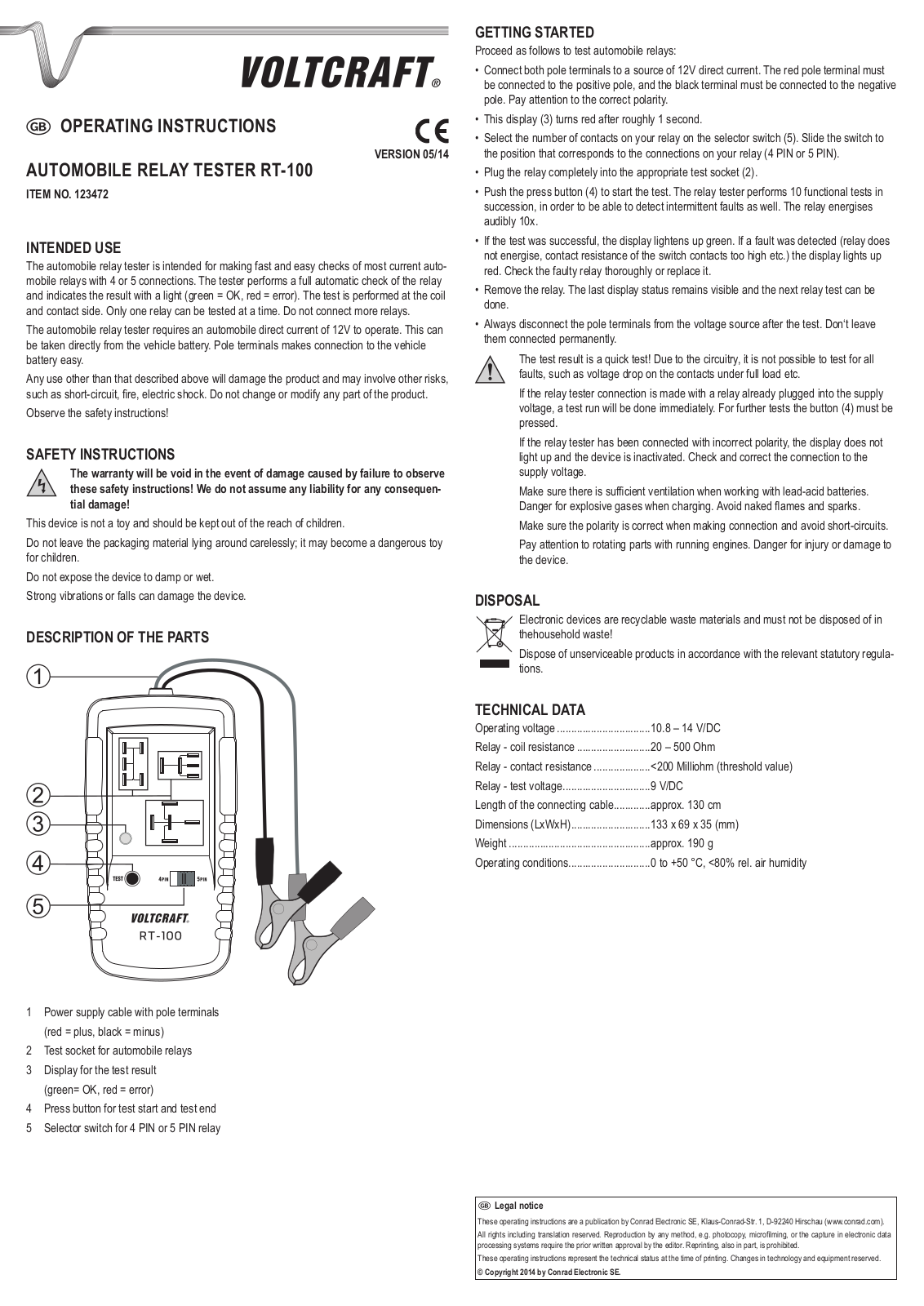
VOLTCRAFT RT-100 User guide [ml]

VOLTCRAFT RT-100 User guide

D BEDIENUNGSANLEITUNG

Version 05/14

KfZ-relaistester rt-100

BEST.-NR. 123472

BestimmungsgemäSSe Verwendung

Der KFZ-Relaistester dient zur schnellen und einfachen Überprüfung der gängigsten KFZRelais mit 4 oder 5 Anschlüssen. Der Tester führt eine vollautomatische Prüfung des Relais durch und zeigt das Ergebnis in einer Leuchtanzeige an (Grün = OK, Rot = Fehler). Der Test erfolgt Spulenund Kontaktseitig. Je Testdurchgang kann nur ein Relais getestet werden. Der Anschluss mehrerer Relais ist nicht zulässig.

Der KFZ-Relaistester benötigt zum Betrieb eine KFZ-Gleichspannung von 12 V. Diese kann direkt an der Fahrzeugbatterie abgenommen werden. Polklemmen erleichtern den Anschluss an die Fahrzeugbatterie.

Eine andere Verwendung als zuvor beschrieben, führt zur Beschädigung dieses Produktes, außerdem ist dies mit Gefahren wie z.B. Kurzschluss, Brand, elektrischer Schlag etc. verbunden. Das Produkt darf nicht geändert bzw. umgebaut werden!

Beachten Sie die Sicherheitshinweise.

SICHERHEITSHINWEISE

Bei Schäden die durch Nichtbeachten der Anleitung verursacht werden, erlischt die Gewährleistung/Garantie! Für Folgeschäden übernehmen wir keine

Haftung!

Dieses Gerät ist kein Spielzeug und gehört nicht in Kinderhände.

Lassen Sie Verpackungsmaterial nicht achtlos herumliegen; diese könnte für Kinder zu einem gefährlichen Spielzeug werden.

Setzen Sie das Gerät keiner Nässe oder Feuchtigkeit aus.

Starke Vibrationen oder ein Herunterfallen können das Gerät beschädigen.

EINZELTEILBEZEICHNUNG

1 Stromversorgungskabel mit Polklemmen (Rot = Plus, Schwarz = Minus)

2 Testsockel für KFZ-Relais

3Anzeige für das Testergebnis (Grün = OK, Rot = Fehler)

4 Taster für Testbeginn und Testende

5 Wahlschalter für 4-PIN oder 5-PIN-Relais

INBETRIEBNAHME

Zum Testen von KFZ-Relais gehen Sie wie folgt vor:

Verbinden Sie die beiden Polklemmen mit einer 12 V Gleichspannungsquelle. Die rote Polklemme muss am Pluspol, die schwarze Polklemme muss am Minuspol angeschlossen werden. Achten Sie auf die korrekte Polarität.

Die Anzeige (3) leuchtet nach ca. 1 s rot.

Wählen Sie am Wahlschalter (5) die Anzahl der Kontakte an Ihrem Relais. Schieben Sie den Schalter in die Position, die mit den Anschlüssen an Ihrem Relais überein stimmt (4PIN oder 5PIN).

Stecken Sie das Relais vollständig in den jeweils passenden Testsockel (2).

Drücken Sie den Taster (4) um den Test zu starten. Der Relaistester führt 10x nacheinander einen Funktionstest durch, um auch Aussetzfehler erkennen zu können. Das Relais zieht 10x hörbar an.

War der Test erfolgreich leuchtet die Anzeige grün auf. Wurde ein Fehler entdeckt (Relais zieht nicht an, Übergangswiderstand an den Schaltkontakten zu hoch etc.), leuchtet die Anzeige rot. Das fehlerhafte Relais sollte genauer Untersucht oder ausgetauscht werden.

Entfernen Sie das Relais. Der letzte Anzeigenstatus bleibt erhalten und der nächste Relaistest kann durchgeführt werden.

Entfernen Sie nach Testende immer die Polklemmen von der Spannungsquelle. Lassen Sie diese nicht dauerhaft angeschlossen.

Das Testergebnis ist ein Schnelltest! Schaltungsbedingt können nicht alle Fehler z.B. Spannungsabfall an den Kontakten unter Volllast etc. getestet werden.

Erfolgt der Anschluss des Relaistesters mit bereits eingestecktem Relais an die Betriebsspannung, wird sofort ein Testdurchlauf durchgeführt. Für weitere Tests muss der Taster (4) gedrückt werden.

Wird der Relaistester verpolt angeschlossen, leuchtet die Anzeige nicht und das Gerät ist inaktiv. Kontrollieren und berichtigen Sie den Anschluss an die Betriebsspannung.

Achten Sie beim Umgang mit Bleibatterien auf ausreichende Belüftung. Bei der Ladung können explosive Gase entstehen. Vermeiden Sie offenes Feuer und Funkenbildung.

Achten Sie beim Anschluss stets auf korrekte Polarität und vermeiden Sie Kurzschlüsse.

Achten Sie bei laufenden Motoren auf drehende Teile. Diese können Sie verletzen oder das Gerät beschädigen.

Entsorgung

Elektrische und elektronische Geräte gehören nicht in den Hausmüll.

Entsorgen Sie das Produkt am Ende seiner Lebensdauer gemäß den geltenden gesetzlichen Bestimmungen.

Technische Daten

Betriebsspannung.................................

10,8 – 14 V/DC

Relais-Spulenwiderstand......................

20 – 500 Ohm

Relais-Kontaktwiderstand.....................

<200 Milliohm (Schwellenwert)

Relais-Testspannung.............................

9 V/DC

Länge Anschlusskabel..........................

ca. 130 cm

Abmessungen (LxBxH).........................

133 x 69 x 35 (mm)

Gewicht.................................................

ca. 190 g

Betriebsbedingungen............................

0 bis +50 °C, <80% rel. Luftfeuchte

D Impressum

Diese Bedienungsanleitung ist eine Publikation der Conrad Electronic SE, Klaus-Conrad-Str. 1, D-92240 Hirschau (www.conrad.com).

Alle Rechte einschließlich Übersetzung vorbehalten. Reproduktionen jeder Art, z. B. Fotokopie, Mikroverfilmung, oder die Erfassung in elektronischen Datenverarbeitungsanlagen, bedürfen der schriftlichen Genehmigung des Herausgebers. Nachdruck, auch auszugsweise, verboten.

Diese Bedienungsanleitung entspricht dem technischen Stand bei Drucklegung. Änderung in Technik und Ausstattung vorbehalten.

© Copyright 2014 by Conrad Electronic SE.

G OPERATING INSTRUCTIONS

Version 05/14

Automobile relay tester rt-100

item No. 123472

Intended use

The automobile relay tester is intended for making fast and easy checks of most current automobile relays with 4 or 5 connections. The tester performs a full automatic check of the relay and indicates the result with a light (green = OK, red = error). The test is performed at the coil and contact side. Only one relay can be tested at a time. Do not connect more relays.

The automobile relay tester requires an automobile direct current of 12V to operate. This can be taken directly from the vehicle battery. Pole terminals makes connection to the vehicle battery easy.

Any use other than that described above will damage the product and may involve other risks, such as short-circuit, fire, electric shock. Do not change or modify any part of the product.

Observe the safety instructions!

SAFETY INSTRUCTIONS

The warranty will be void in the event of damage caused by failure to observe these safety instructions! We do not assume any liability for any consequen-

tial damage!

This device is not a toy and should be kept out of the reach of children.

Do not leave the packaging material lying around carelessly; it may become a dangerous toy for children.

Do not expose the device to damp or wet. Strong vibrations or falls can damage the device.

DESCRIPTION OF THE PARTS

1 Power supply cable with pole terminals (red = plus, black = minus)

2 Test socket for automobile relays

3 Display for the test result (green= OK, red = error)

4 Press button for test start and test end 5 Selector switch for 4 PIN or 5 PIN relay

GETTING STARTED

Proceed as follows to test automobile relays:

Connect both pole terminals to a source of 12V direct current. The red pole terminal must be connected to the positive pole, and the black terminal must be connected to the negative pole. Pay attention to the correct polarity.

This display (3) turns red after roughly 1 second.

Select the number of contacts on your relay on the selector switch (5). Slide the switch to the position that corresponds to the connections on your relay (4 PIN or 5 PIN).

Plug the relay completely into the appropriate test socket (2).

Push the press button (4) to start the test. The relay tester performs 10 functional tests in succession, in order to be able to detect intermittent faults as well. The relay energises audibly 10x.

If the test was successful, the display lightens up green. If a fault was detected (relay does not energise, contact resistance of the switch contacts too high etc.) the display lights up red. Check the faulty relay thoroughly or replace it.

Remove the relay. The last display status remains visible and the next relay test can be done.

Always disconnect the pole terminals from the voltage source after the test. Don‘t leave them connected permanently.

The test result is a quick test! Due to the circuitry, it is not possible to test for all faults, such as voltage drop on the contacts under full load etc.

If the relay tester connection is made with a relay already plugged into the supply voltage, a test run will be done immediately. For further tests the button (4) must be pressed.

If the relay tester has been connected with incorrect polarity, the display does not light up and the device is inactivated. Check and correct the connection to the supply voltage.

Make sure there is sufficient ventilation when working with lead-acid batteries. Danger for explosive gases when charging. Avoid naked flames and sparks.

Make sure the polarity is correct when making connection and avoid short-circuits.

Pay attention to rotating parts with running engines. Danger for injury or damage to the device.

Disposal

Electronic devices are recyclable waste materials and must not be disposed of in

thehousehold waste!

Dispose of unserviceable products in accordance with the relevant statutory regulations.

Technical Data

Operating voltage..................................

10.8 – 14 V/DC

Relay - coil resistance...........................

20 – 500 Ohm

Relay - contact resistance.....................

<200 Milliohm (threshold value)

Relay - test voltage...............................

9 V/DC

Length of the connecting cable.............

approx. 130 cm

Dimensions (LxWxH)............................

133 x 69 x 35 (mm)

Weight...................................................

approx. 190 g

Operating conditions.............................

0 to +50 °C, <80% rel. air humidity

G Legal notice

These operating instructions are a publication by Conrad Electronic SE, Klaus-Conrad-Str. 1, D-92240 Hirschau (www.conrad.com).

All rights including translation reserved. Reproduction by any method, e.g. photocopy, microfilming, or the capture in electronic data processing systems require the prior written approval by the editor. Reprinting, also in part, is prohibited.

These operating instructions represent the technical status at the time of printing. Changes in technology and equipment reserved.

© Copyright 2014 by Conrad Electronic SE.

Loading...
+ 2 hidden pages