

Page 1
Operating manual
EN
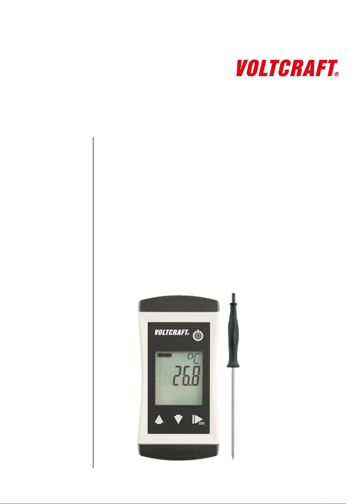
PTM-120
Thermometer with fixed insertion
probe
Permanently connected sensor
Waterproof
Precise and fast
Page 2

Table of contents
Table of contents
1 Legal address of the manufacturer................................................................................................... 4
2 About this documentation ................................................................................................................. 5
2.1 Foreword............................................................................................................................................... 5
2.2 Purpose of the document...................................................................................................................... 5
2.3 Correctness of content.......................................................................................................................... 5
2.4 Layout of this document........................................................................................................................ 5
2.5 Further information ............................................................................................................................... 6
3 Safety ................................................................................................................................................... 7
3.1 Explanation of safety symbols .............................................................................................................. 7
3.2 Foreseeable misuse ............................................................................................................................. 7
3.3 Safety instructions ................................................................................................................................ 7
3.4 Intended use ......................................................................................................................................... 8
3.5 Qualified personnel............................................................................................................................... 9
4 Description ........................................................................................................................................ 10
4.1 Scope of delivery ................................................................................................................................ 10
4.2 Job description.................................................................................................................................... 10
5 The product at a glance ................................................................................................................... 11
5.1 The PTM-120...................................................................................................................................... 11
5.2 Display elements ................................................................................................................................ 11
5.3 Operating elements ............................................................................................................................ 11
6 Operation........................................................................................................................................... 13
6.1 Commissioning ................................................................................................................................... 13
6.1.1 Explanation ......................................................................................................................................... 13
6.2 Configuration ...................................................................................................................................... 13
6.2.1 Explanation ......................................................................................................................................... 13
6.2.2 Opening the configuration menu......................................................................................................... 13
6.2.3 Configuring parameters of the configuration menu............................................................................. 14
6.2.4 Adjustment of the measuring input ..................................................................................................... 15
6.2.5 Configuring parameters of the adjustment menu................................................................................ 16
7 Bases for measurement ................................................................................................................... 18
7.1 Possible measuring errors .................................................................................................................. 18
7.1.1 Immersion depth ................................................................................................................................. 18
7.1.2 Surface effects and poor heat transfer ............................................................................................... 18
7.1.3 Cooling / evaporation.......................................................................................................................... 18
7.1.4 Response time.................................................................................................................................... 18
7.1.5 Limit values......................................................................................................................................... 18
8 Maintenance ...................................................................................................................................... 19
8.1 Operating and maintenance notices ................................................................................................... 19
8.2 Battery ................................................................................................................................................ 19
8.2.1 Battery indicator.................................................................................................................................. 19
8.2.2 Changing battery ................................................................................................................................ 19
8.3 Calibration and adjustment service..................................................................................................... 20
8.3.1 Certificates.......................................................................................................................................... 20
9 Error and system messages............................................................................................................ 22
2 / 25 B-H86.0.0C.DB214-1.0
Page 3

Table of contents
10 Disposal............................................................................................................................................. 23
11 Technical data................................................................................................................................... 24
12 Service ............................................................................................................................................... 25
12.1 Manufacturer....................................................................................................................................... 25
B-H86.0.0C.DB214-1.0 3 / 25
Page 4

1 | Legal address of the manufacturer PTM-120
1 Legal address of the manufacturer
Conrad Electronic SE
Klaus-Conrad-Str. 1
D-92240 Hirschau
http://www.conrad.com
WEEE reg. no. DE 28001718
4 / 25 B-H86.0.0C.DB214-1.0
Page 5

PTM-120 About this documentation | 2
2 About this documentation
2.1 Foreword
Read this document carefully and familiarise yourself with the operation of the product
before you use it. Keep this document ready to hand and in the immediate vicinity of
the product so that it is available to the personnel/user for reference at all times in
case of doubt.
The product was developed according to the state of the art and fulfils the requirements of the applicable European and national Directives. All corresponding documents are available from the manufacturer.
Only technically qualified persons are permitted to carry out commissioning, operation,
maintenance and decommissioning. The qualified personnel must have carefully read
and understood the operating manual before beginning any work.
2.2 Purpose of the document
– This document describes the operation and maintenance of the product.
– Provides important information for working safely and efficiently with the product.
– In addition to the quick reference guide with all relevant legal and safety content in
hard copy, this document is a detailed reference option for the product.
2.3 Correctness of content
The contents of this document were checked for corrected and are subject to a continuous correction and updating process. This does not rule out potential errors. In the
event that errors are discovered or in case of suggestions for improvement, please inform us immediately via the indicated contact information in order to help us make this
document even more user-friendly.
2.4 Layout of this document
Description
Each chapter is explained at the beginning in the description.
Prerequisite
All mandatory prerequisites are then listed for each step.
Instruction
Tasks to be carried out by the personnel / user are represented as numbered instructions. Adhere to the sequence of the specified instructions.
Representation
Shows an illustrative instruction or a configuration of the product.
Formula
Some instructions include a formula for a general understanding of a configuration,
programming or a setting of the product.
B-H86.0.0C.DB214-1.0 5 / 25
Page 6

2 | About this documentation PTM-120
Outcome of an action
Result, consequence or effect of an instruction.
Emphases
In order to simplify legibility and provide a clearer overview, various sections / information are emphasised.
– 1234 Display elements
– Mechanical controls
– Product functions
– Product labels
– Cross-reference [}p.5]
– Foot notes
2.5 Further information
Software version of the product:
– V1.2 or later
For the exact product name, refer to the type plate on the rear side of the product.
NOTE
For information about the software version, press and hold the ON button to switch on
the product for longer than 5 seconds. The series is shown in the main display and the
software version of the product is shown in the secondary display.
6 / 25 B-H86.0.0C.DB214-1.0
Page 7
PTM-120 Safety | 3
3 Safety
3.1 Explanation of safety symbols
DANGER
This symbol warns of imminent danger which can result in death, severe bodily injury,
or severe property damage in case of non-observance.
CAUTION
This symbol warns of potential dangers or harmful situations which can cause damage
to the device or to the environment in case of non-observance.
NOTE
This symbol indicates processes which can have a direct influence on operation or
can trigger an unforeseen reaction in case of non-observance.
3.2 Foreseeable misuse
The fault-free function and operational safety of the product can only be guaranteed if
generally applicable safety precautions and the device-specific safety instructions for
this document are observed.
If these notices are disregarded, personal injury or death, as well as property damage
can occur.
DANGER
Incorrect area of application!
In order to prevent erratic behaviour of the product, personal injury or property damage, the product must be used exclusively as described in the chapter Description
[}p.10] in the operating manual.
– Do not use in safety / Emergency Stop devices!
– The product is not suitable for use in explosion-prone areas!
– The product must not be used for diagnostic or other medical purposes on pa-
tients!
– The product is not intended to come into direct contact with food. For measure-
ment in foods, samples must be taken and discarded after the measurement!
3.3 Safety instructions
This product has been designed and tested according to the safety requirements for
electronic measuring devices.
B-H86.0.0C.DB214-1.0 7 / 25
Page 8
3 | Safety PTM-120
CAUTION
Erratic behaviour!
On suspicion that the product can no longer be operated without danger, it must be
decommissioned and prevented from recommissioning with appropriate labelling. The
safety of the user can be impaired by the device if, for example, if it shows visible
damage, it no longer works as specified or if it was stored for an extended period of
time under unsuitable conditions.
– Visual inspection!
– In case of doubt, send the product to the manufacturer for repair or maintenance!
CAUTION
Stab injury!
Products with insertion probes entail the risk of stab injuries due to the pointed probe
design.
– Handle insertion probes with care!
– Fit a protective cap on the measuring probe!
NOTE
If the product is stored at a temperature above 50 °C, or is not used for an extended
period of time, the batteries must be removed. Leaks from the batteries are avoided as
a result.
NOTE
This product does not belong in children's hands!
NOTE
The sensor handle, connecting cable and product housing are not designed for continuous contact with foods.
Designed for continuous contact with foods in accordance with EC Regulation 1935 /
2004:
– The temperature sensor from the measuring tip to approx. 1 cm before the end of
the stainless steel tube.
For this purpose, also refer to
2 Technical data [}24]
3.4 Intended use
The product is a water-protected thermometer. It is designed for precise and instantaneous temperature measurements in the following media:
– Food
– Liquids
– Gases
– Soft plastic materials
– Bulk material
8 / 25 B-H86.0.0C.DB214-1.0
Page 9

PTM-120 Safety | 3
See Technical data [}p.24].
3.5 Qualified personnel
For commissioning, operation and maintenance, the relevant personnel must have adequate knowledge of the measuring process and use of the measurements, for which
purpose this document makes a valuable contribution. The instructions in this document must be understood, observed and followed.
In order to ensure that no risks arise from the interpretation of the measurements in
the concrete application, the user must have additional technical knowledge, because
the user is liable in case of damage/danger due to misinterpretation as a result of inadequate technical knowledge.
B-H86.0.0C.DB214-1.0 9 / 25
Page 10

4 | Description PTM-120
4 Description
4.1 Scope of delivery
Please check to ensure the completeness of the product after opening the package.
You should find the following components:
– Quick reference guide
– Handheld measuring device, ready for operation, including batteries
4.2 Job description
The product offers precision, speed and reliability in a compact, ergonomic housing.
Additional impressive features include the dust-proof and waterproof design in accordance with IP 65/67 and the 3-line illuminated display, which offers overhead display at
the push of a button. The product can be switched on, switched off and configured and
the measurements and parameters can be adjusted and held with the operating elements. The permanently connected temperature sensor is designed for a measuring
range from -70 °C to 250 °C and provides exact measuring results within a few
seconds. Use of the silicone cable and silicone handle at a maximum temperature of
250 °C should be limited to 2 hours. Permanent use is permissible at temperatures up
to 230 °C.
10 / 25 B-H86.0.0C.DB214-1.0
Page 11

PTM-120 The product at a glance | 5
5 The product at a glance
5.1 The PTM-120
LCD Display PTM-120 PTM-120
5.2 Display elements
Display
Battery indicator Evaluation of the battery status
Unit display Display of units, if applicable, with unstable symbol
or type of mode, min/max/hold
Main display Measurement of the current temperature or value
Auxiliary display Measurement of the current temperature in min/
5.3 Operating elements
On / Off button
Press briefly Switch on the product
Long press Switch off the product
Up / Down button
Press briefly Display of the min/max value
Long press Reset the min/max value of the current measure-
Both simultaneously Rotate display, overhead display
for min/max/hold
max/hold mode with unit
Activate / deactivate lighting
Reject changes in a menu
Change value of the selected parameter
ment
B-H86.0.0C.DB214-1.0 11 / 25
Page 12

5 | The product at a glance PTM-120
Function key
Press briefly Freeze measurement
Return to measurement display
Call up next parameter
Long press, 2s Open menu, frozen measurement is displayed
Close menu, changes are saved
12 / 25 B-H86.0.0C.DB214-1.0
Page 13

6.1.1 Explanation
Description
Prerequisite
Instruction
Outcome of an action
PTM-120 Operation | 6
6 Operation
6.1 Commissioning
The product is switched on with the On/Off button. It may be necessary to configure
the product after switching on. See Configuration [}p.13].
– Sufficiently full batteries are inserted in the product.
– Press On/Off button.
Information about the configuration of the product appears in the display.
POFF
T.OF
T.SL
The product is now ready for measurement.
Automatic shutoff
Zero point correction
Gradient correction
6.2 Configuration
6.2.1 Explanation
The following steps describe how to adapt the product for your purposes.
NOTE
There are various configuration parameters available depending on the product version and configuration. They can differ depending on the product version and configuration.
Automatic shut-off activated. The product is
switched off if no buttons have been pressed after
the adjusted time
If a zero point correction of the temperature sensor
was made
If a gradient correction of the temperature sensor
was made
6.2.2 Opening the configuration menu
Description
Prerequisite
Instruction
B-H86.0.0C.DB214-1.0 13 / 25
In order to configure the product, you must first open the Configuration menu. The
menu is opened as shown in the illustration.
– The product is switched on.
1. Press the Function key for 2 seconds to open the Configuration menu.
2. (ONF appears in the display. Release the function key.
3. By briefly pressing the Function key, you can scroll through the parameters. Select
the parameter you would like to configure.
4. When you have selected the desired parameter, change the parameter to the desired value with the Up button and the Down button.
5. The changes are saved after running through the entire Configuration menu. STOR
appears in the display. The Configuration menu can be exited from any arbitrary
parameter by pressing and holding the Function key for 2 seconds. The changes
made up that point are saved.
Page 14

6 | Operation PTM-120
Representation
Outcome of an action
6.2.3 Configuring parameters of the configuration menu
Description
Prerequisite
Instruction
Representation
Call up menu Next parameter Change value Save changes Discard
changes
2s Press: Single
step
Hold: Rapid
change
The Configuration menu is closed after the last parameter.
2s 2s
NOTE
If the product is switched off without saving the configuration, the last save value is reproduced on the next start-up of the product.
The following representation shows the available parameters and various configuration options.
– The Configuration menu is open. See Opening the configuration menu [}p.13].
1. Select the desired parameter you would like to configure.
2. Adjust the desired configuration in the selected parameter with the Up button and
Down button.
3. The available configuration options are listed for each parameter in the following
representation.
Parameter Values Meaning
Alarms
AL.
AL.LO
AL.K,
Shut-off time
POFF
OFF
ON
BEEP
L,TE
-70.0 .. AL.K,
AL.LO .. 250.0
OFF
15 30 60 120 240
No active alarm
Alarm alerting via text display, acoustic signal and
flashing of the backlighting
Alarm alerting via text display and acoustic signal
Alarm alerting via text display and flashing of the
backlighting
Min. alarm limit; a min. alarm is triggered when the
value is undercut, e.g. at -94.0 °F
Max. alarm limit; a min. alarm is triggered when the
value is exceeded, e.g. at 482.0 °F
No automatic shut-off
Automatic shut-off after a selected time in minutes,
during which no buttons have been pressed
14 / 25 B-H86.0.0C.DB214-1.0
Page 15

Backlighting
L,TE
Temperature unit
UN,T
Factory settings
IN,T
PTM-120 Operation | 6
OFF
15 30 60 120 240
ON
°(
°F
NO
YES Reset product to factory settings. IN,T DONE appears
Backlighting deactivated
Automatic shut-off of the backlighting after a selected time in seconds, during which no buttons have
been pressed
No automatic shut-off of the backlighting
Temperature display in °C
Temperature display in °F
Use current configuration
in the display
Outcome of an action
6.2.4 Adjustment of the measuring input
Description
Prerequisites
Instruction
The changed value is saved and the Configuration menu is closed. STOR appears in
the display. If necessary, the product is restarted automatically in order to adopt the
changed values.
NOTE
The configuration is closed if no button is pressed for 2 minutes. Any changes made
up to that point are not saved. C.END appears in the display.
The temperature input can be adjusted with the zero point correction and the gradient
correction. If an adjustment is made, you change the pre-adjusted factory settings.
This is signalled with the T.OF or T.SL when the product is switched on. The standard
settings of the zero point value and the gradient value is 0.00. It signals that no correc-
tion is made.
In order to adjust the product, you must first open the Adjustment menu. The menu is
opened as shown in the illustration.
– Sufficiently full batteries are inserted in the product.
– The product is switched off.
– Ice water, regulated precision water baths or a water bath with a reference meas-
urement are available as a reference.
1. Press and hold the Down button.
2. Press the On/Off button to switch on the product and open the Configuration
menu. Release the Down button. The display shows the first parameter.
3. By briefly pressing the Function key, you can scroll through the parameters. Select
the parameter you would like to configure.
4. When you have selected the desired parameter, change the parameter to the desired value with the Up button and the Down button.
B-H86.0.0C.DB214-1.0 15 / 25
Page 16

6 | Operation PTM-120
5. In order to save the new parameter value, press and hold the Function key for
longer than 1 second.
Representation
Call up menu
Hold Release
Outcome of an action
The Configuration menu is closed after the last parameter.
NOTE
If the product is switched off without saving the configuration, the last save value is reproduced on the next start-up of the product.
6.2.5 Configuring parameters of the adjustment menu
Description
Prerequisites
Instruction
Representation
The following representation shows the available parameters and various configuration options.
The Adjustment menu is open. See Adjustment of the measuring input [}p.15].
1. Select the desired parameter you would like to configure.
2. Adjust the desired configuration in the selected parameter with the Up button and
Down button.
3. The available configuration options are listed for each parameter in the following
representation.
Parameter Values Meaning
Formula
Example calculation
Zero point correction
T.OF
0.00
-5.00 .. 5.00
No zero point correction
Zero point correction in °C. and/or at °F -9.00 ..
9.00
Gradient correction of the temperature
T.SL
0.00
-5.00 .. 5.00
No gradient correction
Gradient correction in %
Zero point correction:
Displayed value = measured value – T.OF
Gradient correction °C:
Display = (measured value – T.OF) * (1 + T.SL / 100)
Gradient correction °F:
Display = (measured value – 32 °F – T.OF) * (1 + T.SL / 100) + 32 °F
– Zero point correction T.OF to 0.00
– Gradient correction T.SL to 0.00
– Display unit UNIT to °C
– Display in ice water -0.2 °C
– Display in ice water setpoint T.OF = 0.0 °C
16 / 25 B-H86.0.0C.DB214-1.0
Page 17

Outcome of an action
PTM-120 Operation | 6
– Display in water bath 36.6 °C
– Display in water bath setpoint T.SL = 37.0 °C
– T.OF = display zero point correction – setpoint zero point
– T.OF = -0.2 °C – 0.0 °C = -0.2 °C
– T.SL = (setpoint gradient correction / (display gradient correction – T.OF) – 1) *100
– T.SL = (37.0 °C / (36.6 °C – (-0.2)) -1) *100 = 0.54
The changed value is saved and the Configuration menu is closed.
NOTE
If the product is switched off without saving the configuration, the last save value is reproduced on the next start-up of the product.
B-H86.0.0C.DB214-1.0 17 / 25
Page 18

7 | Bases for measurement PTM-120
7 Bases for measurement
7.1 Possible measuring errors
7.1.1 Immersion depth
Liquids
Gases
7.1.2 Surface effects and poor heat transfer
Surface temperature
Immerse to a depth of at least 20 mm and then stir. Otherwise, measuring errors can
occur due to the heat transmission of the sensor tube if the immersion depth is too
shallow.
Immerse as far as possible into the gas to be measured so that the measuring sensor
is subjected to a heavy flow.
Special measuring sensors are required for this purpose. Surface characteristics,
design of the measuring sensor, heat transfer and environmental temperature influence the measurement result.
Air temperature
Response time T
Temperature range
90
NOTE
Thermally conductive paste between the measuring sensor and surface can also increase measurement accuracy in some cases.
7.1.3 Cooling / evaporation
The measuring sensor should be dry; otherwise the temperature measurement is too
low.
7.1.4 Response time
An adequate wait time must be observed for the measuring process before reading
the measured value. The response time T90 describes the time in which the displayed
measured value reached 90% of the end value. See Technical data [}p.24].
7.1.5 Limit values
CAUTION
Destruction of the measuring sensor!
When conducting measurements in media with high or very low temperatures, there is
a risk that the measuring sensor is not designed for such extremes.
– The limit values must be observed!
18 / 25 B-H86.0.0C.DB214-1.0
Page 19

PTM-120 Maintenance | 8
8 Maintenance
8.1 Operating and maintenance notices
NOTE
The product and temperature probe must be handled with care and used in accordance with the technical data. Do not throw or strike.
NOTE
If the product is stored at a temperature above 50 °C, or is not used for an extended
period of time, the batteries must be removed. Leaks from the batteries are avoided as
a result.
8.2 Battery
8.2.1 Battery indicator
If the empty frame in the battery display blinks, the batteries are depleted and must be
replaced. However, the device will still operate for a certain length of time.
If the BAT display text appears in the main display, the battery voltage is no longer adequate for operation of the product. Now the battery is fully depleted.
8.2.2 Changing battery
DANGER
Danger of explosion!
Using damaged or unsuitable batteries can generate heat, which can cause the batteries to crack and possibly explode!
– Only use high-quality and suitable alkaline batteries!
CAUTION
Damage!
If the batteries have different charge levels, leaks and thus damage to the product can
occur.
– Use new, high-quality batteries!
– Do not use different types of batteries!
– Remove depleted batteries and dispose of them at a suitable collection point!
NOTE
Unnecessary screwing places the water-tightness of the product, among other things,
at risk and should be avoided.
B-H86.0.0C.DB214-1.0 19 / 25
Page 20

8 | Maintenance PTM-120
NOTE
Read the following handling instructions before replacing batteries and follow them
step by step. If disregarded, the product could be damaged or the protection from
moisture could be diminished.
Description
Prerequisites
Instruction
Outcome of an action
Proceed as follows to replace the batteries.
– The product is switched off.
– A suitable PH1 is available
1. Unscrews the Phillips screws and remove the cover.
2. Carefully replace the two Mignon AA batteries. Ensure that the polarity is correct!
It must be possible to insert the batteries in the correct position without using
force.
3. The O-ring must be undamaged, clean and positioned at the intended depth. In order to facilitate assembly and avoid damage, a suitable grease can be applied.
4. Fit the cover on evenly. The O-ring must remain at the intended depth!
5. Tighten the Phillips screws.
The product is now ready for use again.
8.3 Calibration and adjustment service
8.3.1 Certificates
The certificates are categorised as ISO calibration certificates and DAkkS calibration
certificates. The purpose of the calibration is to verify the precision of the measuring
device by comparing it with a traceable reference.
NOTE
The ISO standard 9001 is applied for the calibration certificates. These certificates
area affordable alternative to the DAkkS calibration certificates and provide information of the traceable reference, a list of individual values and documentation.
NOTE
The DAkkS calibration is based on DIN EN ISO/17025, the accreditation basis recognised worldwide. These certificates offer high-quality calibration and consistently high
quality. DAkkS calibration certificates can only be issued by accredited calibration
laboratories which have demonstrated their expertise in accordance with DIN EN ISO/
IEC 17025. The ISO calibration includes any necessary adjustment with the purpose
of minimising a deviation of the measuring device.
DAkkS calibration certificates are accompanied with a list of individual measurements
before and after the adjustment, documentation and, if applicable, graphic representation, calculation of the expanded measuring uncertainty and traceability to the national
standard.
20 / 25 B-H86.0.0C.DB214-1.0
Page 21

PTM-120 Maintenance | 8
NOTE
Only the manufacturer can check the basic settings and make corrections if necessary.
B-H86.0.0C.DB214-1.0 21 / 25
Page 22

9 | Error and system messages PTM-120
9 Error and system messages
Display Meaning Possible causes Remedy
----
No display,
unclear characters or no
response
when buttons are
pressed
BAT
ERR.1
ERR.2
SYS ERR
No suitable measuring probe connected
Measurement far
outside of the measuring range
Battery depleted
System error
Product is defective
Battery depleted Battery depleted Replace battery
Measuring range exceeded
Measuring range is
undercut
System error Error in the product Switch product on/off
Incorrect measuring
probe
Measuring probe or
product defect
Battery depleted
Error in the product
Product is defective
Measurement too
high
Incorrect measuring
probe connected
Measuring probe or
product defect
Measurement too
low
Measuring probe or
product defect
Connect a suitable measuring probe
Measurement leaves the
permissible range
Send in for repair
Replace battery
Send in for repair
The measurement is above
the permissible range
Check measuring probe
Send in for repair
The measurement is below
the permissible range
Check measuring probe
Send in for repair
Replace batteries
Send in for repair
22 / 25 B-H86.0.0C.DB214-1.0
Page 23

10 Disposal
NOTE
The device must not be disposed of with household waste. If the product is disposed
of, please take it to a municipal collection point, where it will be transported to a disposal company in accordance with requirements of hazardous goods laws. Otherwise,
return it to us, freight prepaid. We will then arrange for the proper and environmentally-friendly disposal. Please dispose of empty batteries at the collection points intended for this purpose.
PTM-120 Disposal | 10
B-H86.0.0C.DB214-1.0 23 / 25
Page 24

11 | Technical data PTM-120
11 Technical data
Measuring range temperature -70.0 .. +250.0 °C (-94.0 .. +482.0 °F)
Accuracy temperature -20 .. +100 °C: ±0.1 K ±1 digit
otherwise: ±0.2 % of measured value ± 2 digits
Response time T90 water (0.4 m/s) approx. 3 s
Measuring cycle approx. 2 measurements per second
Temperature connections Permanently connected Pt1000 sensor (EN 60751)
Display 3-line segment LCD, additional symbols, illuminated (adjustable
white, permanent illumination)
Additional functions Min/max/hold, alarm (optical and acoustic)
Compensation Offset and gradient correction
Housing Break-proof ABS housing
Protection rating IP65 / IP67
Dimensions L*W*H
[mm]
Weight 150 g, incl. battery and sensor
Operating conditions -20 to 50 °C; 0 to 95 % r.h. (temporarily 100 % r.h.)
Storage temperature -20 to 70 °C
Current supply 2*AA battery (included in the scope of delivery)
Current requirement/
battery life
Battery indicator 4-stage battery status indicator,
Auto-power-OFF function The device switches off automatically if this is activated
Directives and standards The devices conform to the following Directives of the Council for
108 * 54 * 28 mm without kink protection
approx. 0.4 mA, approx. 2 mA with lighting
Service life > 5000 hours with alkaline batteries (without backlighting)
Replacement indicator for depleted batteries: "BAT"
the harmonisation of legal regulations of the Member States:
2014/30/EU EMC Directive
2011/65/EU RoHS
Applied harmonised standards:
EN 61326-1:2013 Emission limits: Class B
Immunity according to Table 2
Additional errors: < 0.5 % FS
EN 50581:2012
24 / 25 B-H86.0.0C.DB214-1.0
Page 25

Contact
PTM-120 Service | 12
12 Service
12.1 Manufacturer
If you have any questions, please do not hesitate to contact us:
VOLTCRAFT
Distributed by
Conrad Electronic SE
Klaus-Conrad-Str. 1
92240 Hirschau, Germany
Tel.: +49 9604 40 87 87
Fax: +49 180 5 312110
kundenservice@conrad.de
WEEE reg. no. DE 28001718
B-H86.0.0C.DB214-1.0 25 / 25
 Loading...