

Page 1

®
Multi-DMM MT-52
BEDIENUNGSANLEITUNG
Seite 2 - 33
Multi-DMM MT-52
OPERATING INSTRUCTIONS Page 34 - 63
Multi-DMM MT-52
NOTICE D’EMPLOI Page 64 - 93
Multi-DMM MT-52
GEBRUIKSAANWIJZING Pagina 94 - 123
Best.-Nr. / Item-No. /
N° de commande / Bestnr.:
12 29 00
Version 03/11
®
°
Page 2
3
Page 3

34
Introduction
Dear customer,
Thank you for making the excellent decision to purchase this Voltcraft® product.
You have acquired a quality product from a brand family which has distinguished itself in the fields of
measuring, charging and network technology thanks to its particular expertise and its continuous innovation.
With Voltcraft®, you will be able to cope even with difficult tasks as an ambitious hobbyist or as a professional user. Voltcraft® offers reliable technology and a great price-performance-ratio.
Therefore, we are absolutely sure: Starting to use Voltcraft will also be the beginning of a long, successful
relationship.
Enjoy your new Voltcraft® product!
Page 4

35
Table of Contents
Introduction ............................................................................................................................................34
Intended Use ........................................................................................................................................36
Operating Controls..................................................................................................................................37
Safety Information ..................................................................................................................................38
Product Description ..............................................................................................................................40
Scope of Delivery ..................................................................................................................................40
Display Indications and Symbols ..........................................................................................................41
Measuring ..............................................................................................................................................42
a) Switching on the Measuring Instrument ......................................................................................42
b) Voltage Measuring “V” ................................................................................................................43
c) Current Measuring “A“ 10 ..........................................................................................................44
d) Resistance Measuring ................................................................................................................46
e) Diode Test ..................................................................................................................................47
f) Continuity test ............................................................................................................................47
g) Capacity Measuring ....................................................................................................................48
h) Contact-Free AC Voltage Detection “NCV” ................................................................................49
i) Frequency Measuring ................................................................................................................49
j) Pulse Width Measurement ..........................................................................................................50
k) Room Temperature and Humidity Measurement ........................................................................50
l) Temperature Measurement with Contact Sensor ......................................................................51
m) Noise Level Measurement ..........................................................................................................51
n) Lighting Measurement ................................................................................................................52
RANGE Button ................................................................................................................................53
REL Key ..........................................................................................................................................54
Hz% Button ......................................................................................................................................54
HOLD Key ........................................................................................................................................54
MODE Button ..................................................................................................................................54
Auto Power OFF Function ................................................................................................................54
Display Illumination ..........................................................................................................................54
Cleaning and Maintenance ....................................................................................................................55
General Information ........................................................................................................................55
Cleaning ..........................................................................................................................................55
Opening Meter ................................................................................................................................56
Replacing the Fuse ..........................................................................................................................56
Inserting/Changing the Batteries ......................................................................................................57
Disposal ................................................................................................................................................58
Disposal of Used Batteries! ..............................................................................................................58
Troubleshooting ....................................................................................................................................59
Technical Data ......................................................................................................................................60
Page 5

36
Intended Use
- Measuring and displaying electric parameters in the range of excess voltage category III (up to max.
600V against ground potential, pursuant to EN 61010-1) and all lower categories. The measuring
device and equipment must not
be used in the overvoltage category CAT IV (e.g. at the low voltage
installation source.)
- Measurement of direct and alternating voltage up to a maximum of 600 V
- Measurement of direct and alternating current up to 10 A
- Measuring resistance values of up to 40 MΩ
- Continuity test (< 50 Ω acoustic)
- Diode Test
- Capacity measuring up to 100 µF
- Frequency measurement up to 10 MHz
- Pulse width display in %
- Temperature measurement with external K-type sensor from -20 to +1300 °C
- Temperature measurement with internal sensor from 0 to +50 °C
- Measuring the relative air humidity form 33 - 99 %
- Measuring the illumination strength up to 40 000 Lux
- Measuring the noise level of 35 - 100 dBC (for orientation measurement)
- Contact-free AC voltage detection “NCV”
The measurement functions are selected using the dial switch. Except for the environmental measuring
ranges of temperature, humidity, noise level and illumination strength, automatic measuring range selection is active in all measuring ranges (autorange).
The two current measuring inputs are secured against overload with ceramic high-performance fuses.
The voltage in the measuring circuit may not exceed 600 V.
The multimeter is operated with a common 9 V alkaline battery block. The device may only be operated
with the specified batteries.
The measuring instrument must not be operated when it is open, i.e. with an open battery compartment or
when the battery compartment cover is missing. Measuring in damp rooms or under unfavourable ambient
conditions is not permitted. Unfavourable ambient conditions are:
- Wetness or high air humidity
- Dust and flammable gases, vapours or solvent,
- thunderstorms or similar conditions such as strong electrostatic fields etc.
For safety reasons, only use measuring cables or accessories which are adjusted to the specifications of
the multimeter when measuring.
Any use other than that described above damages the product. Moreover, this is linked to dangers such
as short circuits, fire, electric shock, etc. No part of the product may be modified or rebuilt!
Read the operating instructions carefully and keep them for later reference.
Always observe the safety instructions!
Page 6

37
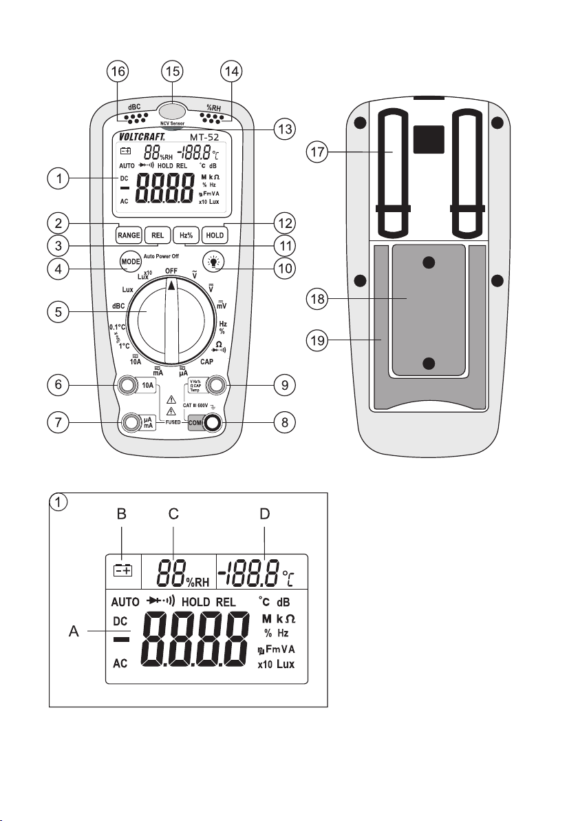
Operating Controls
(see fold-out page)
1 Display
A Main display with measuring unit and additional functions
B Symbol for battery change
C Permanent display of the relative air humidity in percent
D Permanent display of the air temperature in degrees Celsius
2 RANGE button
3 REL key
4 MODE button
5 Dial switch
6 10 A measuring jack
7 µA/mA measuring jack
8 COM measuring jack (reference potential, “Minus”)
9 VΩ measuring jack (with commensurability “Plus”)
10 Light button for display lighting
11 Hz/% button for function switching in the voltage, power and frequency range
12 HOLD key
13 NVC lighted display for AC voltage detection
14 Sensor aperture for indoor air humidity measurement (relative humidity and temperature)
15 Light sensor
16 Sensor aperture for sound volume measurement
17 Clamp for measuring prod attachment
18 Battery compartment
19 Foldable mounting brackets
Page 7
38
Safety Information
Please read through the operating instructions completely before using the product for
the first time; they include important information necessary for correct operation.
The guarantee/warranty will be void if damage is incurred resulting from non-compliance
with the operating instructions. We assume no liability for any consequential damage!
We do not assume any liability for property damage and personal injury caused by
improper use or non-compliance with the safety instructions! In such cases the warranty/guarantee is void.
This device left the manufacture’s factory in a safe and perfect condition.
We kindly request that you as a user observe the safety instructions and warnings contained in this operating manual to preserve this condition and to ensure safe operation!
Please pay attention to the following symbols:
An exclamation mark in a triangle shows important notes in these operating instructions
that should be strictly observed.
Ꮨ
The triangle containing a lightning symbol warns against danger of an electric shock or of
the impairment of the electrical safety of the device.
☞
The “hand” symbol informs you that there are special tips and hints concerning the operation.
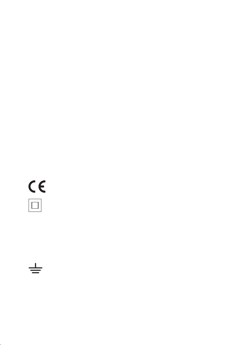
This product has been CE-tested and meets the necessary European guidelines.
Class 2 insulation (double or reinforced insulation)
CAT II Overvoltage category II for measurements on electric and electronic devices connected to the
mains supply with a power plug. This category also covers all smaller categories (e.g. CATI for
measuring signal and control voltages).
CAT III Overvoltage category III for measuring in building installation (e.g. outlets or sub-distribution).
This category also covers all smaller categories (e.g. CATII for measuring electronic devices).
Ground potential
Page 8

39
The unauthorized conversion and/or modification of the product is inadmissible for reasons of safety and
approval (CE).
Consult an expert when in doubt as to the operation, the safety or the connection of the device.
meters and accessories are not toys and have no place in the hands of children.
On industrial sites, the accident prevention regulations of the association of the industrial workers’
society for electrical equipment and utilities must be followed.
In schools, training centres, computer and self-help workshops, handling of meters must be supervised
by trained personnel in a responsible manner.
Before measuring voltages, always make sure that the meter is not set to a measuring range for currents.
The voltage between the measuring instrument connection points and earth must never exceed 600 V
DC/AC in CAT III.
The measuring prods have to be removed from the measured object every time the measuring range is
changed.
Be especially careful when dealing with voltages higher than 50 V AC or 75 V DC. Even at these voltages
it is possible to receive a fatal electric shock if you touch electrical conductors.
Check the measuring device and its measuring leads for damage before each measurement. Never
carry out any measurements if the protecting insulation is defective (torn, ripped off etc.)
To avoid electric shock, do not to touch the connections/measuring points directly or indirectly during mea-
surements. During measuring, do not grip beyond the grip range markings (which you can feel) present on
the measuring prods.
Do not use the multimeter just before, during or just after a thunderstorm (lightning! / high-energy overvoltage!). Please make sure that your hands, your shoes, your clothing, the floor, switches and switching
components are dry.
Avoid operation in direct proximity to strong magnetic or electromagnetic fields, transmitter aerials or HF
generators. This could affect the measurement.
If you have reason to believe that the device can no longer be operated safely, disconnect it immediately and make sure it is not unintentionally operated. It must be assumed that safe operation is no longer
possible if:
- the device shows visible damage,
- the device no longer works and
- the device was stored under unfavourable conditions for a long period of time or
- after it was exposed to extraordinary stress caused by transport.
Do not switch the meter on immediately after it has been taken from a cold to a warm environment. The
condensation that forms might destroy your device. Allow the device to reach room temperature before
switching it on.
Do not leave the packaging material lying around carelessly since such materials can become dangerous toys in the hands of children.
You should also heed the safety instructions in each chapter of these instructions.
Page 9
40
Product Description
The multimeter (referred to as DMM in the following) indicates measured values on the digital display. The
measured value display of the DMM comprises 4000 counts (count = smallest display value). Voltage and
current measurement is performed as an effective median value.
The measuring device includes 4 environmental measuring functions for relative humidity, temperature
(air and sensor measurement), linear noise level (for orientation of noise sources) and strength of illumination. The lighting sensor includes an IR filter that only measures the visible light range.
The display can be lit for a if you are working in a badly lit environment.
If the DMM is not operated for approx. 30 minutes, it automatically switches off. This saves battery power
and extends the period of operation. The meter can be used for do-it-yourself or for professional applications.
For better readability, the DMM can also be optimally mounted with the clip on the rear.
The measuring leads are equipped with transport protection caps at the plugs and measuring prods.
Remove them before using the measuring leads.
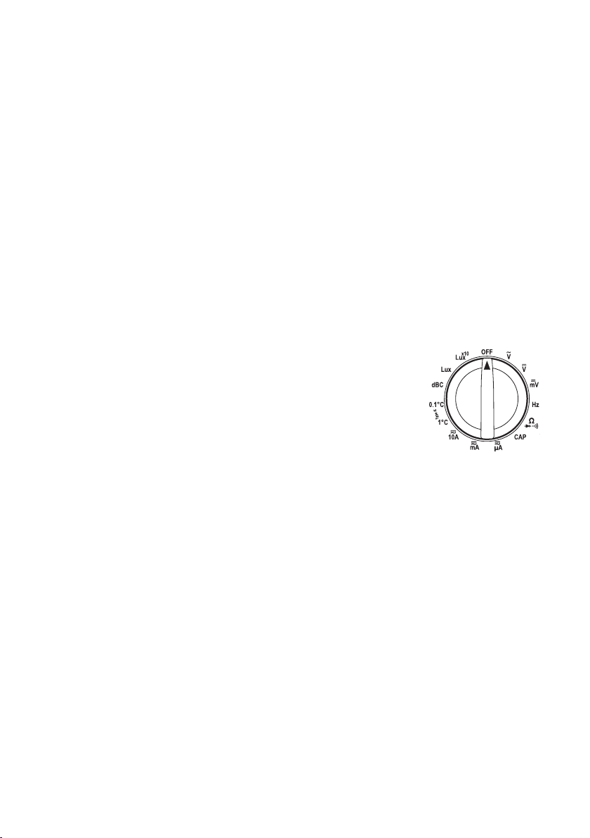
Rotary control (4)
The individual measuring functions are selected via a rotary switch. The
automatic range selection is active if the “auto” symbol is displayed. The
appropriate range of measurement is set individually for each application.
If the meter switch is set to “OFF”, the meter is switched off. Always turn the
device off when it is not in use.
Scope of Delivery
Multimeter
9V block battery
Safety measuring cable
Wire temperature sensor (K-type, measuring range -20 to 230°C)
K-type adapter
Operating instructions
Page 10
41
Display Indications and Symbols
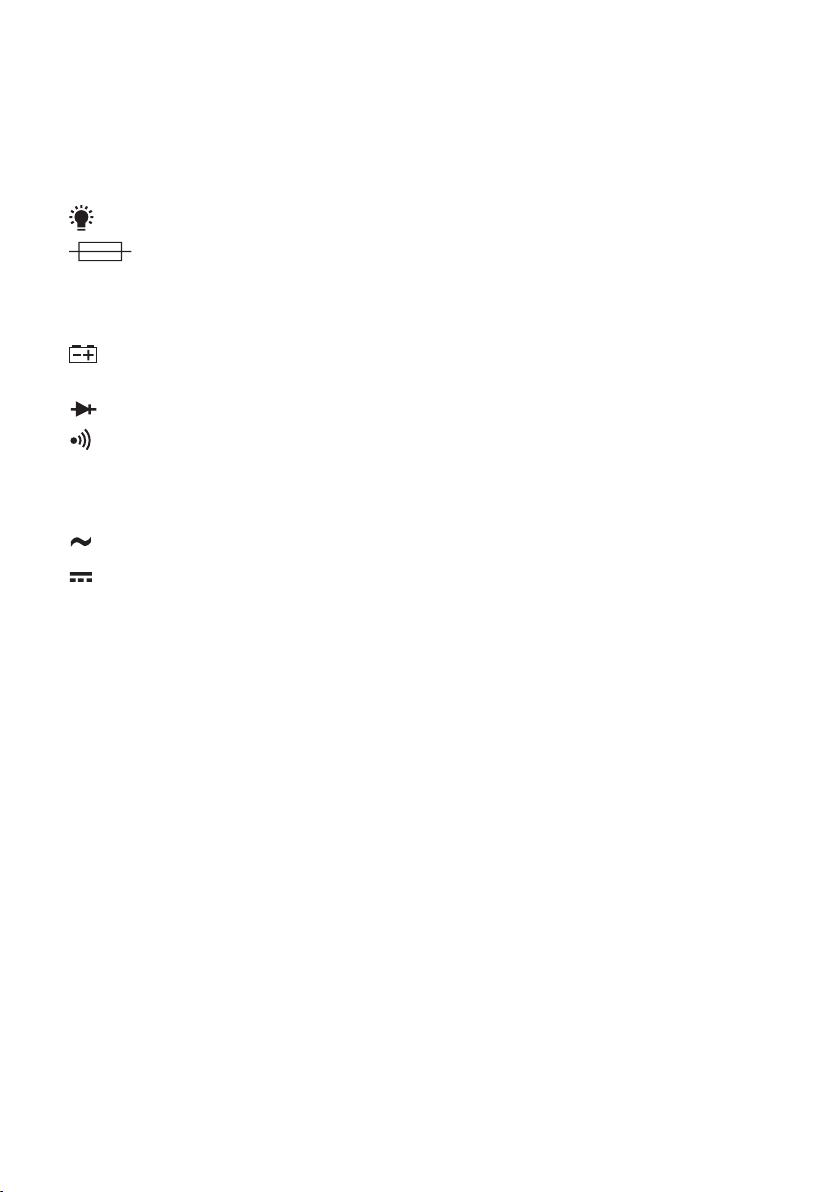
This is a summary of all possible symbols and information on the MT-52.
Auto means “automatic measuring range selection”
Symbol for display illumination
Symbol for the integrated fuses
OL or I Overload = the measuring range was exceeded
OFF Switch position “Measuring device off”
Battery replacement symbol; please replace the batteries immediately to avoid measuring errors!
Symbol for the diode test
Symbol for the acoustic continuity tester
dBC Symbol for noise level measuring range (C-characteristic = linear)
CAP Capacity measuring range
AC Alternating current for voltage and current
DC Direct current for voltage and current
- Polarity indication in case of minus potential
mV Millivolt (exp.-3)
V Volt (unit of electric potential difference or voltage)
µA Microampere (exp.-6)
mA Milliampere (exp.-3)
A Ampere (unit of electric current)
Ω Ohm (unit of electric impedance)
kΩ Kilo Ohm (exp.3)
MΩ Mega Ohm (exp.6)
Hz Hertz (unit of frequency)
% Pulse length in % (pulse pause)
°C Temperature unit (°Celsius)
dB Noise level unit (decibel)
Lux Unit and measuring range of illumination strength
Page 11

42
%RH Relative air humidity
nF Nanofarad (exp.-9), unit of electric capacity
µF Microfarad (exp.-6)
mF Millifarad (exp.-3)
Measuring
Do not exceed the maximum permitted input values. Do not touch any circuits or
parts of circuits if there could be voltages higher than 50 V ACrms or 75 V DC present
within them. Danger to life!
Before measuring, check the connected measuring accessories for damage such as,
for example, cuts, cracks or squeezing. Never use defective measuring equipment!
Danger to life!
During measuring, do not grip beyond the tangible grip range markings present on
the test prods.
Measuring is only permitted when the battery and fuse compartment is closed.
Ꮨ
You may only connect the measuring leads to the measuring device that are required
for measuring operation. Remove all measuring lines not required from the device
for safety reasons.
☞
As soon as “OL“ or “I” (overload) appears on the display, you have exceeded the measuring
range.
a) Switching on the Measuring Instrument
Turn the rotary control (4) to the corresponding measurement function. To switch off turn the rotary control to “OFF”. Always turn the device off when it is not in use.
Prior to working with the meter, you have to insert the enclosed battery. Insertion and changing of the battery is described in the “Cleaning and Maintenance” chapter.
Page 12
43
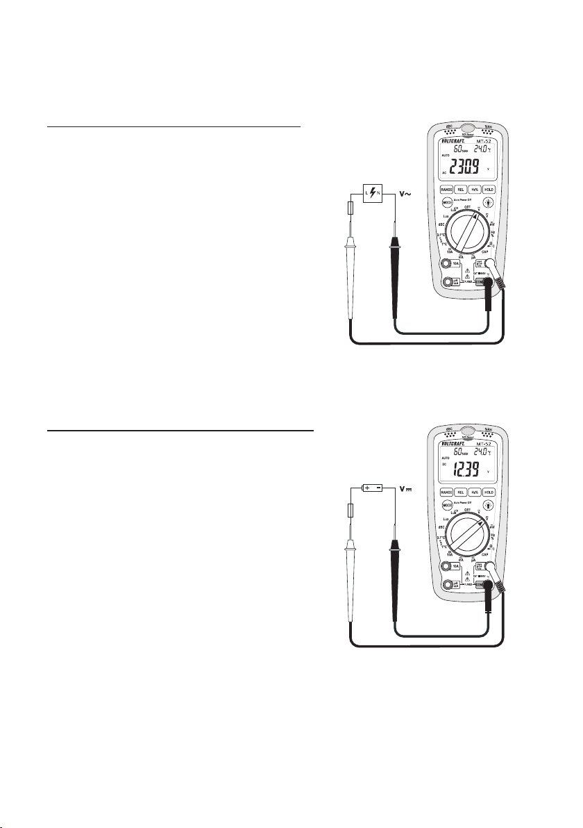
b) Voltage Measuring “V”
The voltage range “V AC/DC” shows an input resistance of >10 MOhm.
Proceed as follows to measure
AC voltages “V-AC”:
- Turn the DMM on and select measuring function “V~”.
- Plug the red measuring lead into the V measuring socket
(9) and the black measuring lead into the COM measuring
socket (8).
- Now connect the two measuring prods to the object to be
measured (power outlet, switch etc.).
- The currently measured value is indicated on the display
- After measuring, remove the measuring lines from the
measured object and turn the DMM off.
☞
Use the “Hz%” button (11) to switch the display to
frequency (Hz) and pulse length (%). Each press
switches the function. Autorange is deactivated.
The mV-AC measuring range can only be selected via manual measuring range selection
(“RANGE” button).
Proceed as follows to measure “V
-DC” direct voltages:
- Turn the DMM on and select measuring function “V=”.
- Plug the red measuring lead into the V measuring socket
(9) and the black measuring lead into the COM measuring
socket (8).
- Now connect the two measuring prods to the object to be
measured (battery, switch etc.). The red measuring tip indicates the positive pole, the black measuring tip the negative
pole.
- The polarity of the respective measured value is indicated
on the display together with the current measured value.
☞
As soon as a minus “-” appears for the direct voltage in front of the measured value, the measured
voltage is negative (or the measuring tips have
been mixed up).
- After measuring, remove the measuring lines from the
measured object and turn the DMM off.
Page 13
44
☞
Use the “Hz%” button (11) to switch the display to frequency (Hz) and pulse length (%).
Each press switches the function. Autorange is deactivated. This enables monitoring of
possible ripple voltage (superimposed alternate voltage). In case of pure direct voltage, the
frequency and % displays are “zero”. Without a measured signal, phantom values may be
displayed. They disappear when a direct voltage is measured.
c) Current Measuring “A“ 10
The voltage in the measuring circuit may not exceed 600 V.
Do not measure any currents above 10 A in the 10Arange and no currents above 400
mA in the µA/mA range, otherwise the fuses trigger.
Measuring >5 A may only be performed for max. 30 seconds and at 15 minute intervals.
Always start current measurements at the highest measurement range and switch down to lower ranges
if necessary. Before changing the measurement range, always shut off the circuit. All current measuring
ranges are secured with fuses and thus protected against overload.
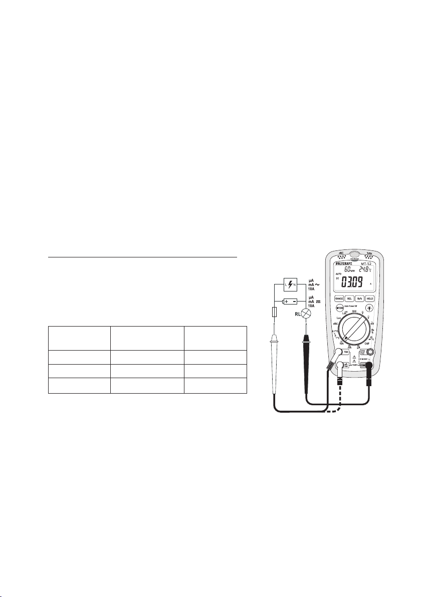
Proceed as follows to measure “A-DC” direct current:
- Turn the DMM on and select measuring function “A”.
The table shows the different measuring functions and
possible measuring ranges. Select your measuring range
and the respective measuring jacks. The display indicates
“DC”.
Measuring Measuring Measuring
function range jacks
µA <4000 µA COM + mAµA
mA 4mA – 399 mA COM + mAµA
10A 400 mA – 10 A COM + 10A
- Insert the red measuring line into the µA/mA or 10A measuring jack. Plug the black measuring line into the COM
socket.
- Now connect the two measuring prods in series to the object to be measured (battery, switch etc.).
The polarity of the respective measured value is indicated on the display together with the measured
value.
☞
When a minus “-” appears in front of the measured value when measuring DC, the
measured voltage is negative (or the measuring lines have been swapped).
After measuring, remove the measuring lines from the measured object and turn the DMM off.
Page 14
45
☞
Use the “Hz%” button (11) to switch the display to frequency (Hz) and pulse length (%).
Each press switches the function. Autorange is deactivated. This enables monitoring of
possible ripple signal (superimposed frequency). In case of pure direct current, the frequency and % displays are “zero”. Without a measured signal, phantom values may be displayed. They disappear when a direct current is measured.
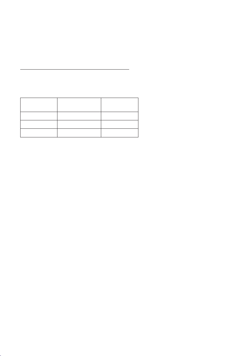
Proceed as follows to measure
AC voltages “A-AC”:
- Turn the DMM on and select measuring function “A”.
The table shows the different measuring functions and possible measuring ranges. Select your measuring range and the respective measuring jacks. The display indicates “DC”.
Measuring Measuring Measuring
function range jacks
µA <4000 µA COM + mAµA
mA 4mA – 399 mA COM + mAµA
A 400 mA – 10 A COM + 10A
- Insert the red measuring line into the µA/mA or 10A measuring jack. Plug the black measuring line
into the COM socket.
- Press “MODE” to switch to the AC measuring range. “AC” appears in the display. Pressing this button again, takes you back etc.
- Now connect the two measuring prods in series to the object to be measured (power circuit, switch
etc.). The measured value is indicated on the display The connection principle corresponds to DC
measurement.
- After measuring, remove the measuring lines from the measured object and turn the DMM off.
☞
Use the “Hz%” button (11) to switch the display to frequency (Hz) and pulse length (%).
Each press switches the function. Autorange is deactivated.
Page 15
46
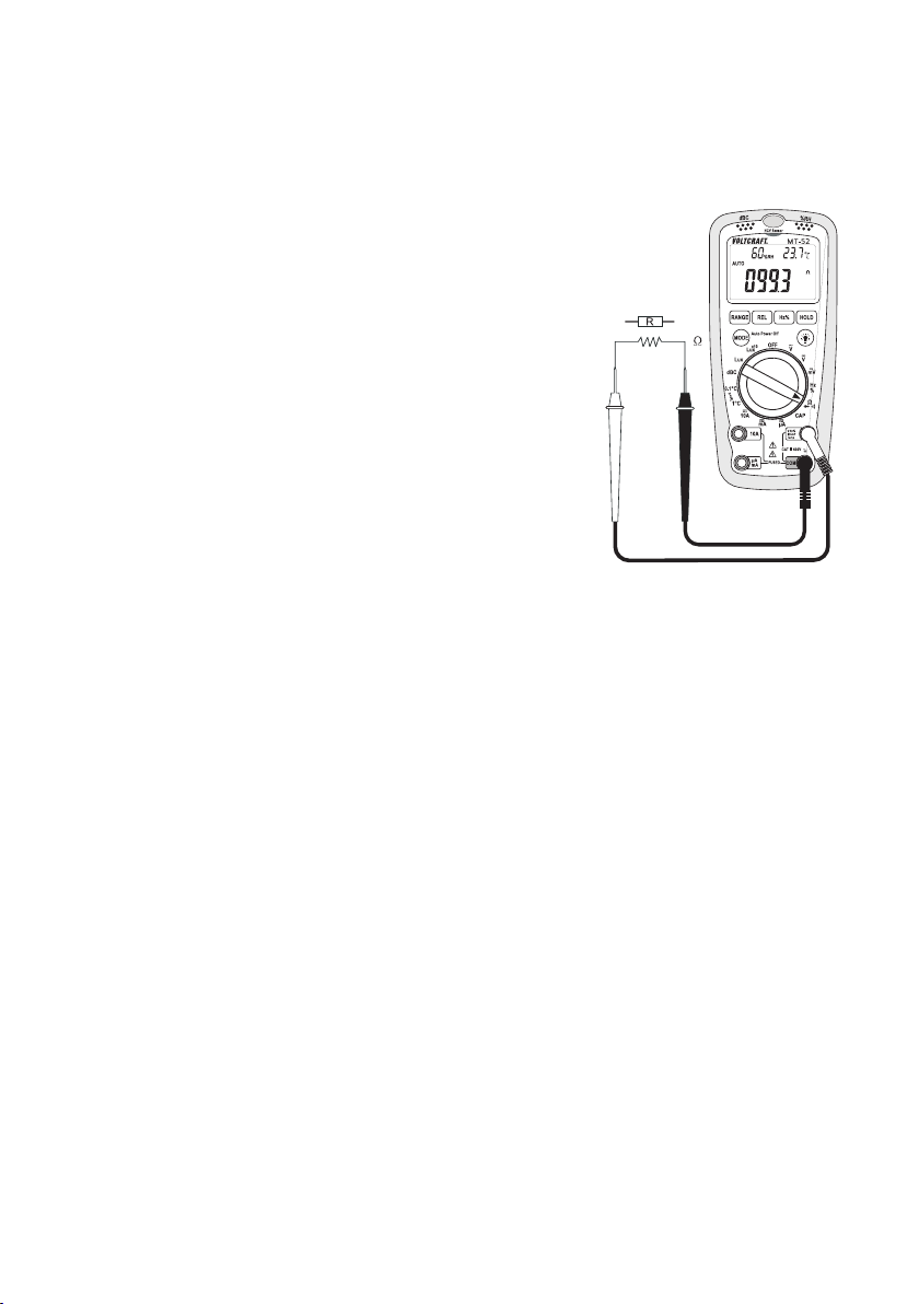
d) Resistance Measuring
Make sure that all the circuit parts, switches and components and other objects of
measurement are disconnected from the voltage and discharged.
- Turn the DMM on and select measuring function “Ω”.
- Plug the red measuring line into the Ω measuring jack (9)
and the black measuring line into the COM measuring jack
(8) .
- Check the measuring lines for continuity by connecting
both measuring prods with one another. The resistance
value must be approximately 0 - 0.5 Ohm (inherent resistance of the measuring lines).
- Now connect the measuring prods to the object to be
measured. As long as the object to be measured is not
high-Ohm or interrupted, the measured value will be indicated on the display. Wait until the displayed value has stabilised. With resistances of >1 MOhm, this may take a few
seconds.
- If “OL” (overload) appears on the display, you have exceeded the measuring range or the measuring circuit has
been broken.
- After measuring, remove the measuring lines from the
measured object and turn the DMM off.
☞
If you carry out a resistance measurement, make sure that the measuring points which you
contact with the test prods are free from dirt, oil, solderable lacquer or the like. Such circumstances can falsify the measured result.
Page 16
47
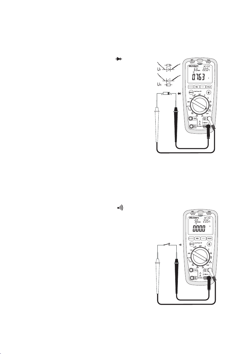
e) Diode Test
Make sure that all the circuit parts, switches and components and other objects of
measurement are disconnected from the voltage and discharged.
- Turn the DMM on and select measuring function .
- Plug the red measuring lead into the V measuring socket
(9) and the black measuring lead into the COM measuring
socket (8).
- Press “MODE” button to switch measurement functions. The
symbol for diode test now appears in the display. Pressing this
button again takes you to the next measuring function.
- Check the measuring lines for continuity by connecting
both measuring prods with one another. The value must be
approximately 0 V.
- Now connect the two measuring prods with the object to
be measured (diode).
- The display shows the continuity voltage “UF” in volt (V). If
“OL” appears, the diode is measured in reverse direction
(UR) or the diode is defective (interruption). Perform a
counter-pole measurement to check.
- After measuring, remove the measuring lines from the measured object and turn the DMM off.
f) Continuity test
Make sure that all the circuit parts, switches and components and other objects of
measurement are disconnected from the voltage and discharged.
- Turn the DMM on and select measuring function .
- Press “MODE” button twice to switch measurement functions. The symbol for continuity test now appears in the
display. Pressing this button again takes you to the first
measuring function etc.
- Plug the red measuring lead into the V measuring socket
(9) and the black measuring lead into the COM measuring
socket (8).
- A continuity value of less than 50 Ohm is identified as continuity; in this case a beep sounds. The impedance value is
displayed up to 399.9 Ohm.
- If “OL” (overload) appears on the display, you have exceeded the measuring range or the measuring circuit has
been broken.
- After measuring, remove the measuring lines from the
measured object and turn the DMM off.
Page 17
48
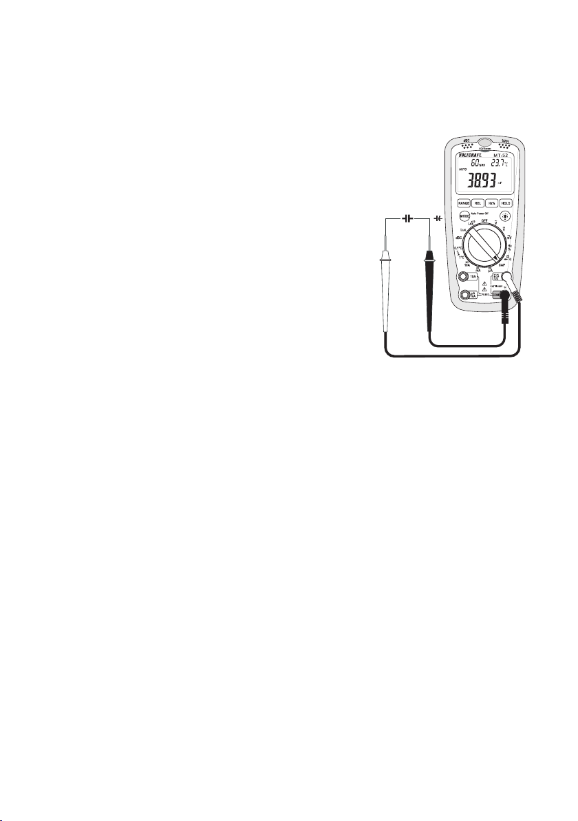
g) Capacity Measuring
Make sure that all the circuit parts, switches and components and other objects of
measurement are disconnected from the voltage and discharged.
- Turn the DMM on and select measuring function “CAP”.
- Plug the red measuring lead into the V measuring socket
(9) and the black measuring lead into the COM measuring
socket (8).
- Connect the measuring prods to the component.
- If “OL” (overload) appears on the display, you have exceeded the measuring range or the measuring circuit has
been broken.
- After measuring, remove the measuring leads from the
measuredobject and turn the DMM off.
Always observe correct polarity for electrolyte capacitators.
Make sure to use measuring leads that are as
short as possible. Long measuring leads may
cause measuring deviations.
Page 18
49
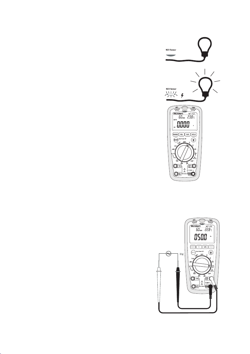
h) Contact-Free AC Voltage Detection “NCV”
The “NCV” detector is placed on the top of
the housing and reacts only to alternate voltages between 200 and 1000 V/AC.
This function is only used for quick search
for alternate voltage-conducting lines and
cables. For work at the power lines, freedom
from voltage must be verified with the traditional contact test method (phase tester)!
- The measuring leads are not required.
- Turn on the DMM and select any measuring function.
Contact-free voltage detection is active in all measuring
functions.
- Move the DMM with the “NCV” sensor (upper housing
edge) along the test object. The detection depth reaches
from approx. 3 cm at 230 V/AC to approx. 8 cm at 1000
V/AC.
- Where a live line is discovered, the “NCV” lighted display
(13) lights up.
- Switch off DMM after measuring.
Shielded lines, lines that are too deep or twisted wires may negatively influence the display.
i) Frequency Measuring
- Turn the DMM on and select measuring function “Hz”.
- Plug the red measuring lead into the V measuring socket
(9) and the black measuring lead into the COM measuring
socket (8).
- Now connect the two measuring prods to the object to be
measured (generator, signal, etc.).
- The currently measured value is indicated on the display
- After measuring, remove the measuring lines from the
measured object and turn the DMM off.
Page 19
50
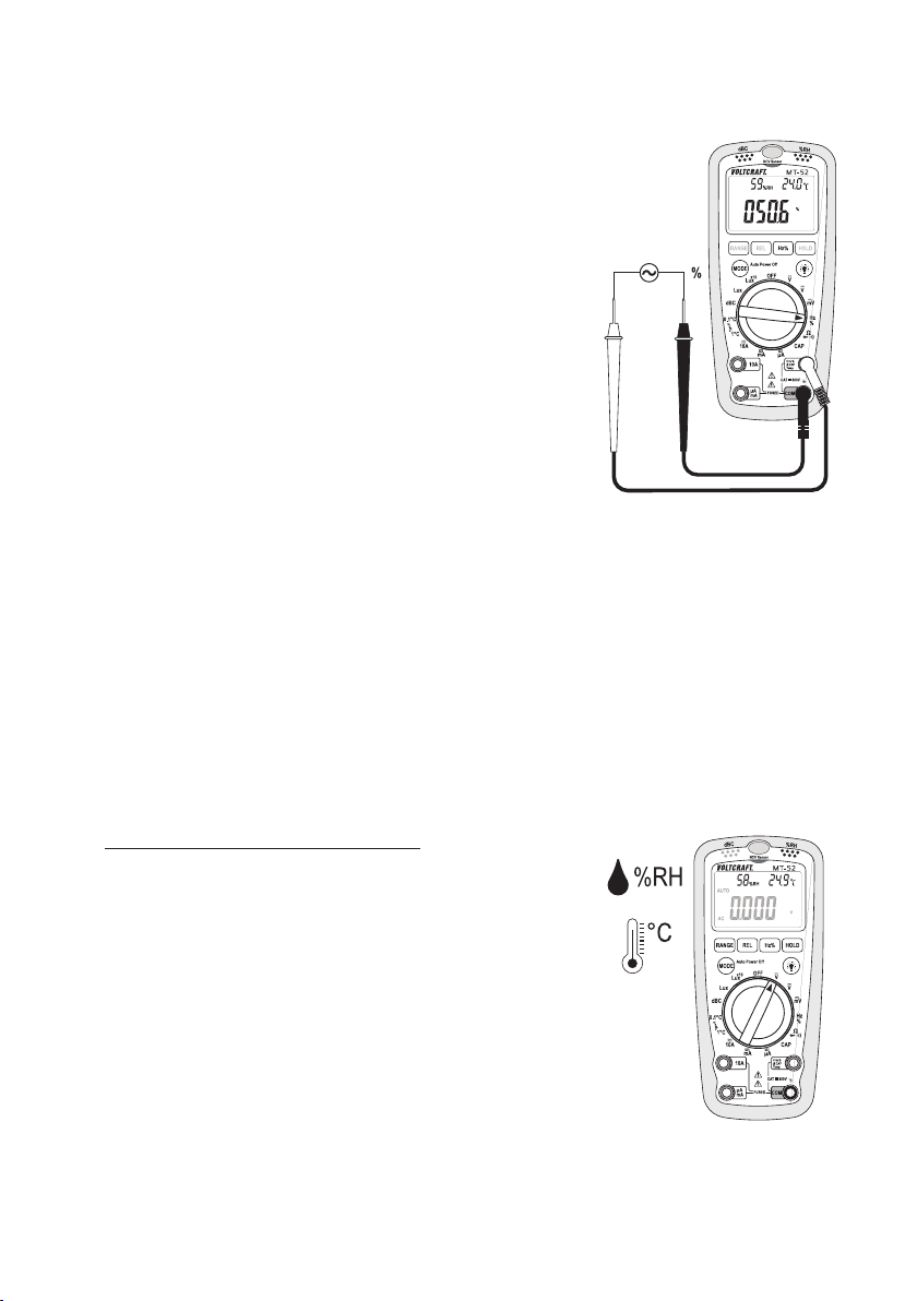
j) Pulse Width Measurement
Pulse width measurement enables measuring of the positive
hal-wave of a measuring signal. The ratio of the positive halfwave to the total signal is displayed. For symmetrical signals
(e.g. sinus), the positive and negative half-waves are the
same length. The display shows approx. 50%.
- Turn the DMM on and select measuring function “Hz”.
- Plug the red measuring lead into the V measuring socket
(9) and the black measuring lead into the COM measuring
socket (8).
- Press “MODE” button to switch measurement functions.
The symbol “%” appears in the display. Pressing this button again takes you to the first measuring function etc.
- Now connect the two measuring prods to the object to be
measured (generator, signal, etc.).
- The currently measured value is indicated on the display
- After measuring, remove the measuring lines from the
measured object and turn the DMM off.
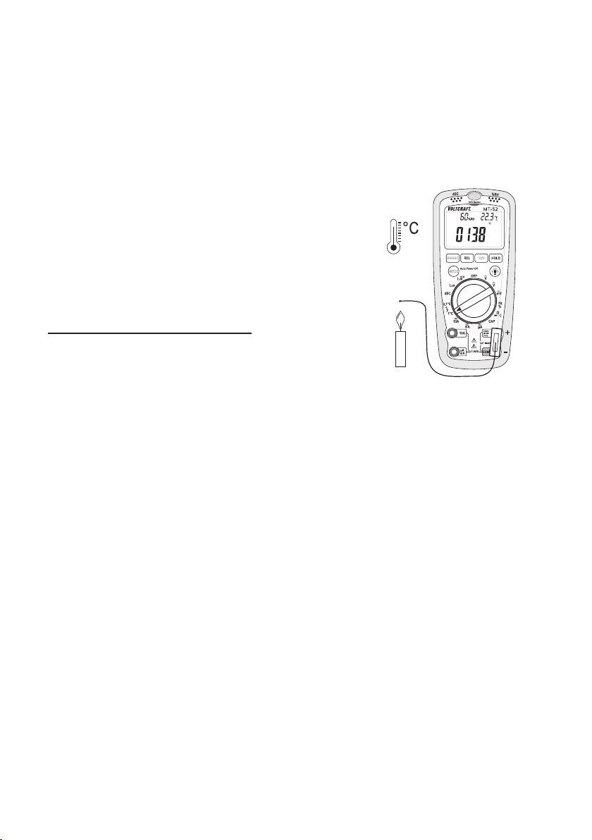
k) Room Temperature and Humidity Measurement
The DMM enables measuring the room temperature and relative humidity via firmly installed sensors. The
two measured values are permanently displayed in the upper display area in measuring operation.
☞
The sensors are located inside the device and react to changes of the measured value with
delays. Wait for at least 30 minutes until the device has adjusted to the ambience conditions.
We recommend waiting for approx. 2 hours to ensure precise measured values.
Proceed as follows for the measurement:
- The measuring leads are not required.
- Turn on the DMM and select any measuring function.
- In the upper left, the display shows the relative humidity in
“%RH” and in the upper right the room temperature in “°C”.
- Wait until the displayed value has stabilised. This may take
up to 2 hours.
- Switch off DMM after measuring.
Page 20
51
The long measuring time due to the build may cause deviations between the displayed
and the “actual” temperature and humidity in case of short measuring durations. Therefore, this product must not be used for very exact measurements (e.g. quality-control
climate monitoring, etc.).
l) Temperature Measurement with Contact Sensor
Contact measurement is only permissible
with powered-down objects. Danger of electric shock!
Due to its build, the included wire sensor is
only designed for a measuring range between -20 and +230 °C. With optional K-type
thermal sensors, the complete measuring
range of the DMM can be used.
Proceed as follows for the measurement:
- Switch on the DMM and select the measuring range according to desired resolution: “1 °C” or “0.1 C”.
- Connect the K-type measuring adapter to the “V” (+) and
“COM” (-) in the correct polarity.
- Connect the sensor to the measuring adapter in the correct polarity. The polarity is marked on the
plug.
- guide the measuring prod to the object to be measured. The measuredvalue is shown in the main
display in °C.
- Switch off DMM after measuring.
The measured temperature must only be applied to the measuring prod. The measuring device must be in the specified environment to prevent measuring errors.
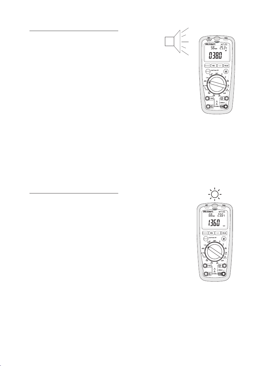
m) Noise Level Measurement
The sound level measurement is used as an orientation measurement to identify sources of sound. Evaluating measurement for documentation, etc. is not possible. The sound level is measured linearly (characteristic “C”), i.e. all sounds (low and high ones) are assessed equally. Thus, you will receive frequency-independent measured values that make comparison easier.
The measuring aperture for sound is at the upper left (16). During measurement, the measuring device
should be aligned at a right angle to the sound source.
Always wear hearing protection when working in loud environments to prevent
damage to your hearing.
Page 21
52
Proceed as follows for the measurement:
- The measuring leads are not required.
- Turn the DMM on and select measuring function “dBC”.
- Align the DMM with the measuring aperture (16) towards
the sound source. Min. distance 1 m.
- The measuring value is shown on the main display.
- Switch off DMM after measuring.
Strong wind (> 10 m/s) may negatively influence the measuring result.
n) Lighting Measurement
The lighting measurement is used to verify the light conditions in living and work rooks, etc. The light
sensor includes a spectral filter that only lets through visible light for measurement
The lighting sensor is placed at the centre top (15). During measurement, the measuring device should
be aligned at a right angle to the light source.
Do not look into any bright light sources. This may lead to visual impairment. Keep
sufficient distance between the DMM and hot sources of light.
Proceed as follows for the measurement:
- The measuring leads are not required.
- Turn the DMM on and select measuring function “Lux”.
- Align the DMM with the light sensor (15) towards the light
source.
- The measuring value is shown on the main display. When
only the middle display segment shows “1”, the measuring
range was exceeded. Switch to the next measuring function “Lux x10” with the dial switch. The indicated measured
value now has to be multiplied by 10.
- Switch off DMM after measuring.
Page 22

53
☞
The included table shows the recommended lighting strengths according to the indications of the international commission for lighting.
Place: Recommended illumination strength in Lux:
Office
Meeting room 200 - 750
Writing room 700 - 1500
Technical drawing 1000 - 2000
Factory
Goods receipt, packing 150 - 300
Visual inspection in production lines 300 - 750
Inspection work 750 - 1500
Assembly line 1500 - 3000
Hotel
Entrance area, wardrobe 100 - 200
Reception area, cash point 200 - 1000
Shop
Staircase 150 - 200
Shop window area 750 - 1500
Hospital
Hospital room, storage 100 - 200
Examination room 300 - 750
Surgical theatre, emergency room 750 - 1500
School
Lecture room, assembly hall 100 - 300
Classroom 200 - 750
Crafts and drawing rooms 500 – 1500
RANGE button
The RANGE button enables manual measuring range selection in the voltage, current and impedance
measuring functions. This button is not active in any other measuring functions.
Every time it is pressed, the auto range function is deactivated (display “Auto” goes out) and switches to
the next higher measuring range. After the largest measuring range, it starts again with the smallest one.
For switching off the manual measuring range selection, keep the “RANGE” button pressed for approx.
2s. The display shows “Auto” again.
Page 23

54
REL key
The REL key enables reference value measuring. The indicated measuring resistance can be reset to
zero, e.g. to avoid including the resistance of for measuring leads in low-ohmic measurements.
Every time it is pressed, the auto range function is deactivated (display “Auto” goes out) The symbol
“REL” is displayed.
To turn the REL function off, press “REL”. To activate the autorange function, keep the “RANGE” button
pressed for approx. 2s. The display shows “Auto” again.
Hz% Key
The Hz% key enables direct switching to the frequency display in voltage and current measuring areas.
Press again to switch to pulse measurement “%”. Press again to switch back to normal mode. Each
press switches the function.
In the “Hz” measuring function, this button is used to switch to the pulse measurement “%”.
HOLD Button
The HOLD button makes it possible to manually capture the currently measured value. When the function is active, the display shows “HOLD”. Pressing the button again switches the function off again.
MODE Button
The MODE button makes it possible to skip through subfunctions. Each press switches the function.
• During current measurement (µA, mA, 10A), the device switches from AC (alternate current) to DC
(direct current).
• From resistance measurement, the device switches to diode measurement and acoustic continuity
test.
Auto power OFF function
The DMM turns off automatically after approx. 30 minutes if no button or rotary switch is operated. This
function protects the battery, saves battery power and extends the service life.
To reactivate the DMM after automatic shutdown, use the rotary switch or press any button (apart from
the light button (10)).
Display illumination
The display can be lit if you are working in a badly lit environment. To switch it on or off, press the “ “
(10) button in measuring operation. Lighting remains on until it is deactivated manually or the DMM switches off automatically after approx. 30 minutes.
Page 24

55
Cleaning and Maintenance
General Information
To ensure the accuracy of the multimeter over an extended period of time, it should be calibrated once a
year.
Apart from occasional cleaning and fuse replacements, the meter requires no servicing.
Information on changing the battery and fuse is provided below.
Regularly check the technical safety of the instrument and measuring leads, e.g. check
for damage to the housing or squashing etc.
Cleaning
Always observe the following safety instructions before cleaning the device:
Live components may be exposed if covers are opened or parts are removed (unless
this can be done without tools).
The connected lines must be disconnected from the measuring device and all measuring objects prior to cleaning or repairing the device. Switch off the DMM.
Do not use any carbon-containing cleaning agents or petrol, alcohol or the like to clean the product. These
could corrode the surface of the meter. Furthermore, the fumes are hazardous to your health and explosive.
Moreover, you should not use sharp-edged tools, screwdrivers or metal brushes or similar for cleaning.
When cleaning the device or the display and the measuring lines, use a clean, lint-free, antistatic, slightly
damp cloth. Allow the product to dry completely before you use it again to conduct measurements.
Page 25
56
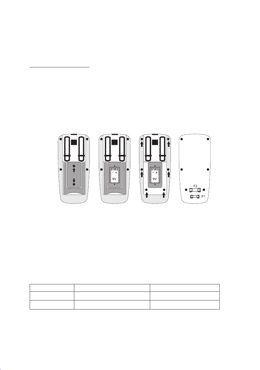
Opening Meter
The connected lines must be disconnected from the measuring device and all measuring objects before the device is opened. Switch off the DMM.
Proceed as follows to open it:
- Disconnect all measuring leads from the meter and switch it off.
- Unscrew and remove the two rear battery compartment screws (18).
- Pull the battery cover (18) from the measuring device at a 90° angle.
- This battery compartment is now accessible.
- Remove the mounting bracket ad remove all six housing screws.
- Draw the housing apart parallel. Make sure that it does not catch.
- The fuses can be accessed now.
- Close the housing again in the reverse order and screw the battery and fuse compartment closed.
- The meter is ready for use once again.
Replacing the Fuse
The current measuring ranges are protected by high-performance fuses. If measuring in this range is no
longer possible, you have to change the fuse.
Proceed as follows for fuse replacement:
- Separate the connected measuring lines from the measuring circuit and the measuring device. Switch
off the DMM.
- Open the housing as described in chapter “Opening the Measuring Device”.
- Replace the defective fuse with a new fuse of the same type and nominal voltage. The fuses have the
following values:
Fuse F1 F2
Value FF 500 mA 660V F10A H 600V
Dimensions 5 x 20 mm 6.3 x 32 mm
- Now close the housing again carefully.
Page 26

57
Using mended fuses or bridging the fuse holder is not permitted for safety reasons.
It may cause fires or arc explosions. Never operate the meter when it is open.
Inserting and Changing the Batteries
Operation of the measuring device requires a 9V battery (e.g. 1604A). You need to insert a new, charged
battery prior to initial operation or when the battery change symbol appears on the display.
Proceed as follows to insert or change the batteries:
- Separate the connected measuring lines from the measuring circuit and the measuring device. Switch
off the DMM.
- Open the housing as described in chapter “Opening the Measuring Device”.
- Replace the flat batteries with new one of the same type. Place a new battery into the battery compartment (18), observing the correct polarity. Observe the correct polarity indicated in the battery
compartment.
- Now close the housing again carefully.
Never operate the measurement device when it is open. !RISK OF FATAL INJURY!
Do not leave flat batteries in the device. Even batteries protected against leaking can
corrode and thus release chemicals which may be detrimental to your health or destroy the battery compartment.
Do not leave batteries lying around carelessly. They could be swallowed by children
or pets. If swallowed, consult a doctor immediately.
Remove the batteries if the device is not used for longer periods of time to prevent
leaking.
Leaking or damaged batteries may cause alkali burns if they come in contact with
the skin. Therefore, use suitable protective gloves.
Make sure that the batteries are not short-circuited. Do not throw batteries into the
fire.
Batteries must not be recharged or dismantled. Danger of explosion!
☞
You can order suitable alkaline batteries stating the following order no.:
Item no. 65 25 09 (please order one).
Only use alkaline batteries, as they are powerful and have a long service life.
Page 27
58
Disposal
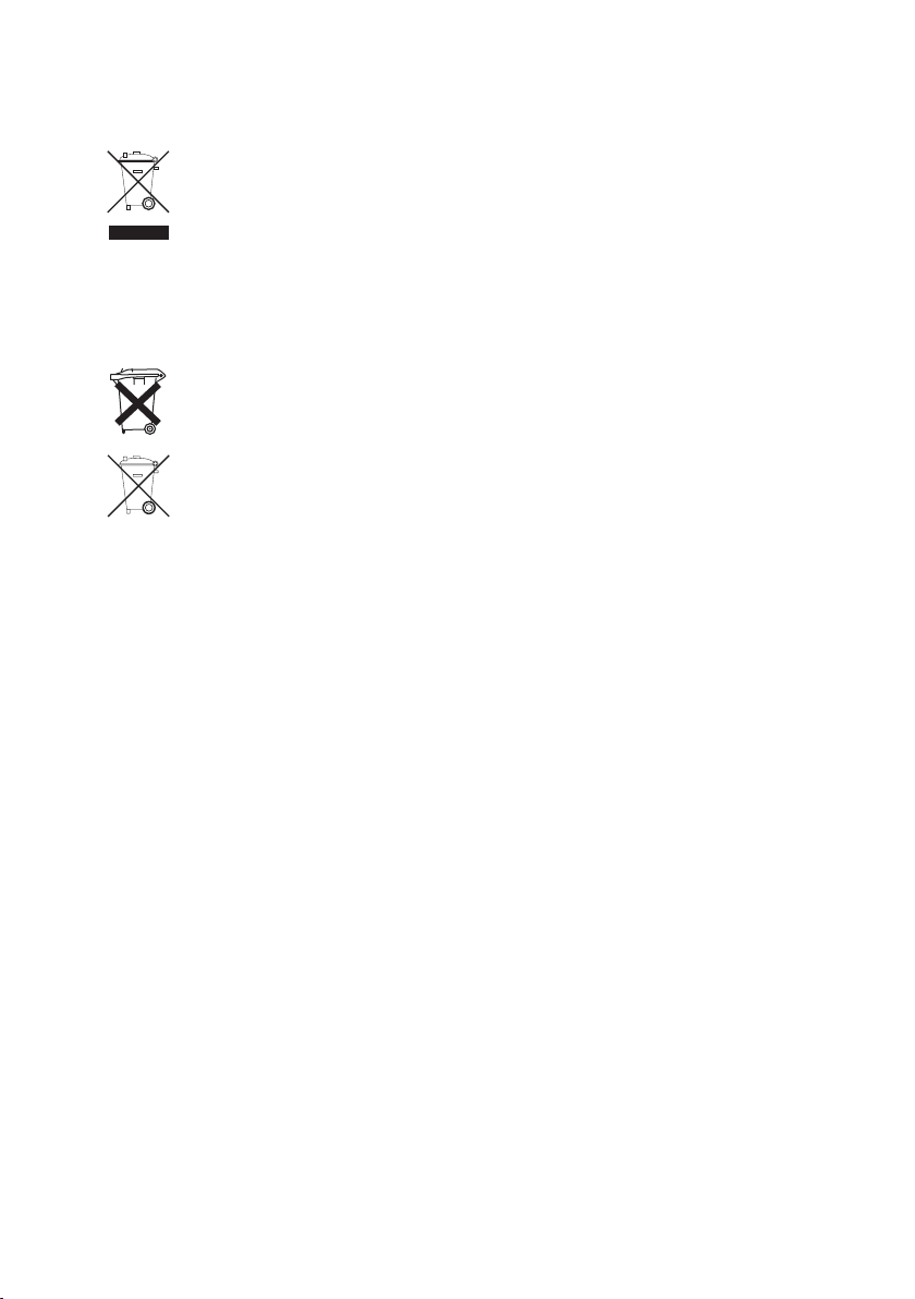
Old electronic devices are recyclable and should not be disposed of in the household
waste. At the end of its service life, dispose of the product at the community collection point
according to the relevant statutory regulations. It is prohibited to dispose of the device in the
household waste.
Disposal of Flat Batteries.
As a consumer you are legally required (Battery Ordinance)to responsibly dispose of all used batteries
and rechargeable batteries; it is forbidden to throw them away with the normal household waste!
Batteries containing toxic substances are marked with the symbols shown, which indicate
they cannot be disposed of in the household waste. The descriptions for the respective heavy metal are: Cd = cadmium, Hg = mercury, Pb = lead. You can return used batteries/rechargeable batteries free of charge at the official collection points of your community, in our stores, or wherever batteries/rechargeable batteries are sold!
You thus fulfil the legal requirements and contribute to protecting the environment!
Page 28
59
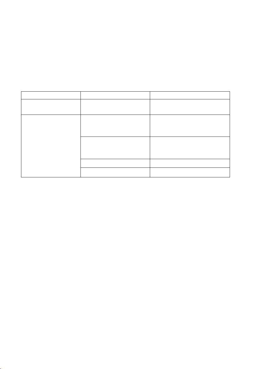
Troubleshooting
In purchasing the DMM, you have acquired a product which has been designed to the state of the art and
is operationally reliable. Nevertheless, problems or errors may occur. For this reason, the following is a
description of how you can eliminate possible malfunctions yourself.
Always follow the safety instructions!
Error Possible cause Remedy
The multimeter Is the battery dead? Check the status.
does not work. Replace batteries.
No measured value Is a wrong measuring function Check the display (AC/DC)
change. activated (AC/DC)? and switch the function
if applicable.
Did you use the wrong Compare the connection with the
measuring sockets? information from the operating
instructions.
Is the fuse defect? Check the fuses.
Is the “HOLD” function activated? Press the “HOLD” button.
Repairs other than those described above may only be carried out by an authorised
specialist. If you have queries about handling the measuring device, our technical
support is available under the following telephone number:
Voltcraft®, 92242 Hirschau, Lindenweg 15, Tel.-No. 0180 / 586,582 7.
Page 29
60
Technical Data
Symbol ........................................................4000 counts
Measuring rate ............................................Approx. 3 measuring operations/second
measuring line length ..................................Approx. 80 cm each
Measuring impedance ................................>10MΩ (V range)
Operating voltage ........................................9V block battery
Working conditions ......................................0 - 40°C (<70%rF)
Operating altitude ........................................max. 3,000 m
Storage temperature....................................-10°C to +60°C (<80%rF)
Weight ........................................................approx. 335 g
Dimensions (LxWxH) ..................................170 x 78 x 48 (mm)
Over-voltage category ................................CAT III 600 V, Impurity level 2
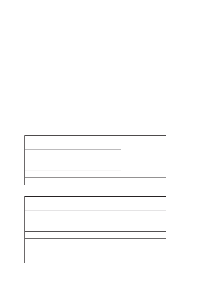
Measurement tolerances
Statement of accuracy in ± (% of reading + display error in counts (= number of smallest points)). The accuracy is valid for one year at a temperature of +23°C ± 5°C, and at a relative humidity of less than 70 %, noncondensing.
Direct voltage (DC)
Range Resolution: Accuracy
400 mV 0.1 mV
4 V 0.001 V ±(1,2 % + 5)
40 V 0.01 V
400 V 0.1 V
±(1,8% + 4)
600 V 1 V
Other Features Overload protection 600 V
Alternate voltage (AC)
Range Resolution: Accuracy
400 mV 0.1 mV ±(1,8% + 20)
4 V 0.001 V
±(1,2% + 5)
40 V 0.01 V
400 V 0.1 V ±(1,8% + 4)
600 V 1 V ±(2,2% + 5)
Other Features Frequency range 50 – 400 Hz;
Effective average value with sinus voltage;
overload protection 600 V
400 mV area only through manual area selection!
Page 30
61
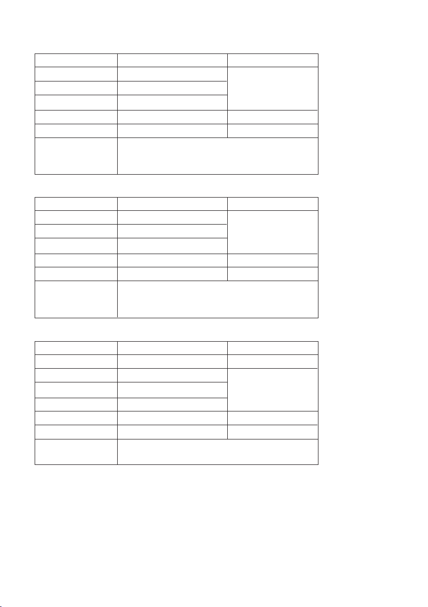
Direct current (DC)
Range Resolution: Accuracy
400 µA 0.1 µA
4000 µA 1 µA ±(1,2% + 2)
40 mA 0.01 mA
400 mA 0.1 mA ±(1,5% + 2)
10 A 0.01 A ±(2,2% + 5)
Other Features Overload protection: Fuses;500 mA 660 V, 10 A 600 V ;
Measuring time limit > 5 A: max. 30 s with
15 min break
Alternate current (AC)
Range Resolution: Accuracy
400 µA 0.1 µA
4000 µA 1 µA ±(1,5% + 3)
40 mA 0.01 mA
400 mA 0.1 mA ±(1,8% + 3)
10 A 0.01 A ±(2,2% + 6)
Other Features Overload protection: Fuses;500 mA 660 V, 10 A 600 V ;
Measuring time limit > 5 A: max. 30 s with
15 min break; frequency range 50 - 400 Hz
Resistance
Range Resolution: Accuracy
400 Ω 0.1 Ω ±(1,8% + 5)
4 kΩ 0.001 kΩ
40 kΩ 0.01 kΩ ±(1,5% + 2)
400 kΩ 0.1 kΩ
4 MΩ 0.001 MΩ ±(2,0% + 2)
40 MΩ 0.01 MΩ ±(2,5% + 2)
Other Features Overload protection 600V;
Measuring voltage: approx. 0.28 V
Page 31
62
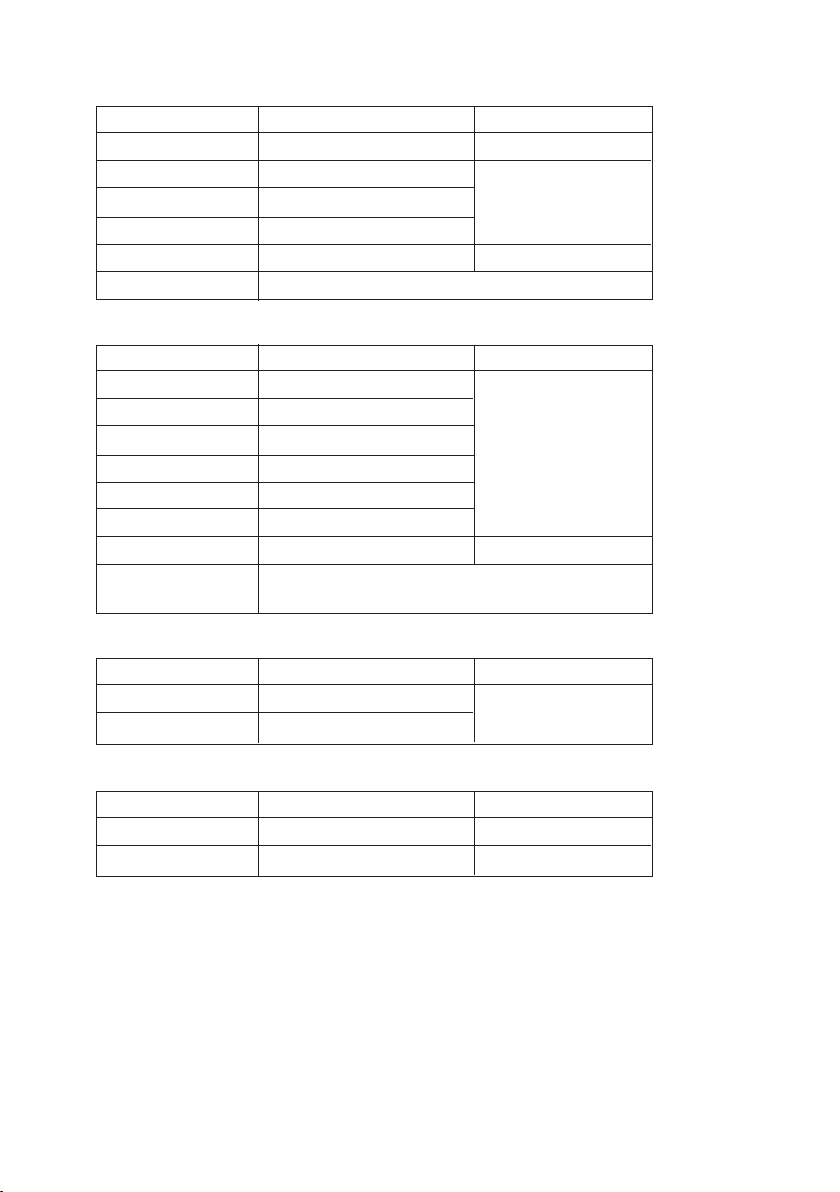
Capacity
Range Resolution: Accuracy
50 nF 0.01 nF ±(5,5% + 25)
500 nF 0.1 nF
5 µF 0.001 µF ±(3,5% + 7)
50 µF 0.01 µF
100 µF 0.1 µF ±(5,0% + 7)
Other Features Overload protection 600 V
Frequency
Range Resolution: Accuracy
5 Hz 0.001 Hz
50 Hz 0.01 Hz
500 Hz 0.1 Hz
±(1,5% + 3)
5 kHz 0.001 kHz
50 kHz 0.01 kHz
500 kHz 0.1 kHz
10 MHz 0.01 MHz ±(1,5% + 4)
Other Features Overload protection 600 V; sensitivity: <1 MHz: >0.5 V;
>1 MHz: >3 V
Temperature contact sensor type K
Range Resolution: Accuracy
-20 to +400 °C 0.1 °C
±(3,0% + 3 °C)
-20 to +1300 °C 1 °C
Relative temperature and relative air humidity:
Range Resolution: Accuracy
0 to +50 °C 0.1 °C ±(3,0% + 3)
33 - 99 %rF 1 %rF ±(3,0% + 5,5)
Page 32
63
Illumination strength
Range Resolution: Accuracy
4000 lux 1 lux ±(6% + 15)
40000 lux 10 lux ±(3,5% + 10)
Colour temperature accuracy of 2856 K; repetition accuracy ± 2%;
Temperature stability: ±0.1 % per °C; light sensor: Silicium photo diode with
spectral filter
Sound level
Range Resolution: Accuracy
35 – 100 dB 0.1 dB ±5,5 dB
Accuracy at 94 dB and 1 kHz sinus; frequency range: 30 Hz – 10 kHz;
Assessment: Characteristic “C” (linear); time assessment: Fast; Microphone:
Condenser microphone
Diode Test
Test voltage approx. 1.5 V
Test current approx. 1 mA
Resolution: 0.001 V
Accuracy ±(10% + 5)
Overload protection: 600 V
Acoustic continuity tester <100 Ω continuous sound, test voltage approx 0.5 V,
overload protection 600 V
NCV: Detection range: 200 – 1,000 V/AC
Do not exceed the maximum permitted input values. Do not touch any circuits or
parts of circuits if they can have higher voltages than 25 V Acrms or 35 V DC. Danger
to life!
 Loading...