

Page 1
The Lupo
Design and function
Self-Study Programme No. 201
1
0
2
o
N
E
M
S
M
A
R
G
O
PR
Y
D
U
T
S
-
F
L
E
Page 2

The Lupo, a new addition to the
subcompact family, extends the
Volkswagen product range.
In spite of its compact dimensions, the Lupo
boasts a specification which stands comparison
with any saloon and is rounded off by a
distinctive design.
Environmental pollution kept to a minimum by
using fuel-efficient, low-emission and quiet
engines as well as recycleable and recycled
plastic parts.
The Lupo conforms to all internationally
recognised safety standards for head-on
collision, side impact, offset collision and rear
collision as well as for rollover.
The small and highly manoeuvrable vehicle
is simply likeable, chic and natural.
The Self-Study Programme
is no Workshop Manual.
2
SSP 201_130
Please always refer to the relevant
Service Literature for all inspection,
adjustment and repair instructions.
SSP 201_134
SSP 201_131
New Important
Note
Page 3

At a glance
The Lupo .......................................................................
Vehicle dimensions, aerodynamics
The car and the environment
Environmental protection, recycling
Body ..............................................................................
Safety bodyshell,
paintwork structure and corrosion protection, high-strength body panels
Soundproofing, Isofix, fabric sliding roof
Front and rear bumpers
Restraint system, airbags
Engines ..........................................................................
Engine-gearbox combination
Engines, roller cam follower,
Power transmission ......................................................
Manual gearbox 085 and gear selection
Manual gearbox 002 and gear selection
Automatic gearbox and gate selection
4
10
18
26
Fuel system ................................................................... 29
Running gear ................................................................
Steering
Front axle/rear axle
Brake system
Front and rear brakes
ESBS
Electrical system ..........................................................
Vehicle electrical system/components
Fitting locations of control units,
Dash panel insert, central locking
Radio generation ’99
Heating, air conditioning system ...............................
Heating, air conditioning system,
Radiator fan control unit,
high pressure sender, system overview, functional diagram
30
38
48
Service ...........................................................................
Special tools
55
3
Page 4
The Lupo
The small LUPO achieves great things in terms
of safety, quality, performance, running gear
and equipment.
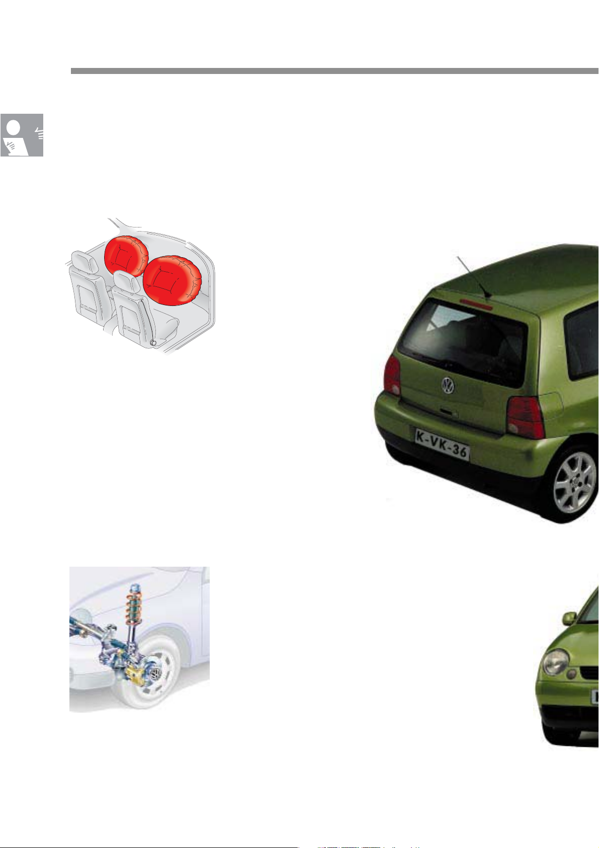
• Safety
The safety bodyshell, belt
tensioners, front airbags
and side airbags mean that the
little Lupo is no baby when it
comes to safety.
SSP 201_174
SSP 201_133
• The running gear
The suspension strut front axle with
wishbones, as well as the torsion beam
rear axle are a winning team and place
the LUPO firmly on the road.
SSP 201_080
4
Page 5
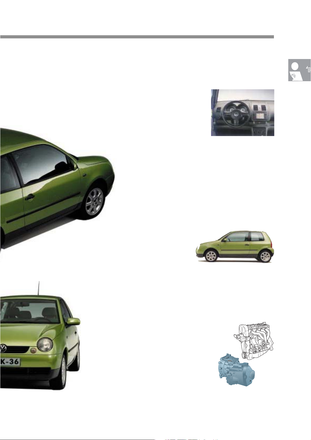
• Equipment level
A 4-seater or 5-seater version can
be specified. Easy Entry seats are
standard for the driver and front
passenger. They exceed the
standard specification.
Also available for the LUPO is a
complete range of extras ranging
from the electric fabric sliding roof
and the air conditioning system to
the navigation system.
• Quality
The Lupo also meets
Volkswagen's recognised
quality standard:
• Narrow body joints
• High-quality materials
SSP 201_168
SSP 201_132
SSP 201_131
• Engines and gearboxes
A choice of four petrol engines and
one
diesel engine in combination with
a 5-speed manual gearbox and a
4-speed automatic gearbox will be
available when the LUPO is
launched on the market.
5
Page 6
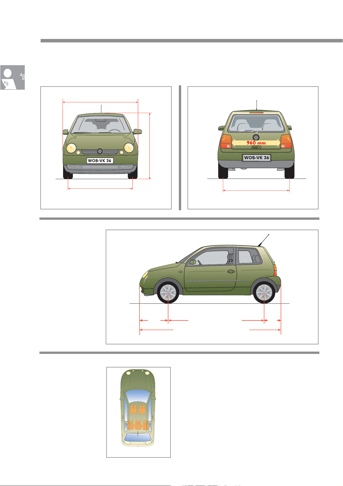
The Lupo
Vehicle dimensions
Width: 1639 mm
Front track width: Rear track width:
1387 mm (4 1/2 J x 13)
1371 mm (5 1/2 J x 13, 6 J x 14)
With a maximum
length of 3527 mm, the
LUPO belongs to the
subcompact class.
m
m
0
6
4
t: 1
h
ig
e
H
SSP 201_010
Tank capacity
34 litres
1400 mm (4 1/2 J x 13)
1384 mm (5 1/2 J x 13, 6 J x 14)
SSP 201_011
The Lupo offers space
for 4 or 5 persons,
depending on the
equipment level.
729
mm
Wheelbase: 2323 mm
Length: 3527 mm
The luggage compartment has a capacity of
139 or 792 litres. The rear seat backrest can be
folded down. The inclination of the rear seat
backrest can be adjusted in two stages in order
475
mm
SSP 201_012
to enlarge the luggage compartment.
SSP 201_007
6
Page 7
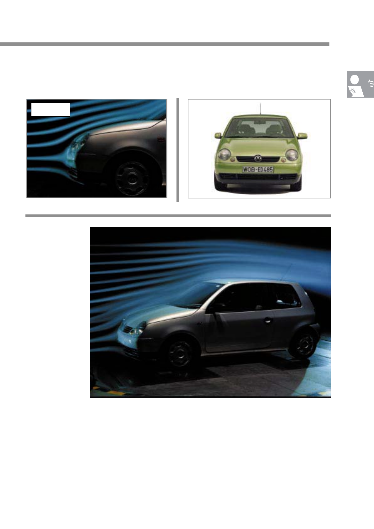
Aerodynamics
cd = 0.32
Aerodynamic
drag
D = 0.62 m
2
A = 1.94 m
SSP 201_018 SSP 201_130
2
One of the main goals in the
development of the LUPO's
aerodynamics was to
streamline the bodyshell in
such a way as to eliminate
additional measures to
improve the vehicle’s
aerodynamics, measures
which involve higher costs
and weight.
SSP 201_020
A streamlined bumper with integral front spoiler,
optimised door mirror, small gap and joint
dimensions as well as flush-fitting windows and
headlights minimise aerodynamic drag and wind
noise.
7
Page 8

The car and the environment
In addition to households, industry,
power stations, heating stations and
industrial agriculture, the car is one
of the principal sources of air
pollution.
Global annual CO2 emissions caused by man
Source: Technical University of Vienna
Other modes of transport
Ocean-going ships
Air traffic
Trucks and buses
Passenger cars
Industry
Power stations and heating
stations
Combustion of biomass
House fires and small
consumers
SSP 201_005
CO2 emissions constitute
approx. 50 percent of the
greenhouse gases which are
responsible for the "manmade" phenomenon of
global warming. Industry,
power stations, households
and small consumers are
responsible a good two thirds
of CO
emissions. Road traffic
2
worldwide accounts for
approx. 12 percent of CO
2
emissions, whereas cars
contribute less than 6 percent.
For Volkswagen, reducing fuel consumption, and
Fuel consumption of cars
supplied by Volkswagen in Germany
along with it CO2 emissions, is one of its main
goals in the development of new automobiles. We
have agreed to reduce the fuel consumption of our
new vehicles by 25 percent between 1990 and
2005. During the period from 1990 to 1995, we
achieved a 10 percent reduction. We plan to
achieve another 15 percent reduction within the
next ten years. The so-called "3-litre car" (a car
Polo SDI
3-litre car
Source: VOLKSWAGEN AG
8
SSP 201_006
which consumes 3 litres of fuel per 100 km) is a
major step towards low-CO
-emission vehicles,
2
both for production and during operation.
Page 9

Recycling
Volkswagen, in association with
disposal firms, runs a Workshop
Disposal Programme. This process
is co-ordinated through the
distribution centre or the importer
in charge in accordance with
prevailing national legislation.
These components can be disposed of
without posing a burden on the environment:
Wo
r
k
s
h
o
g
is
to
e
n
ive
s
ia
r
p
m
m
a
in
p
D
i
s
p
m
m
o
s
a
l
o
t
ive
f
re
e
m
a
e
n
t
d
i
s
p
o
s
a
l
m
w
l
w
id
e
ra
n
g
e
p
o
n
e
h
a
rg
e
c
o
n
c
a
s
t
e
o
f
fe
r
o
f
n
e
r
n
d
is
s
f
t
s
a
n
d
i
n
g
t
h
e
p
o
o
s
a
l
r
e
:
o
f
a
c
o
o
f
c
t
t
e
r
s
a
n
d
o
s
a
Pr
o
D
a
u
m
e
d
Ad
v
ic
e
n
v
i
ro
I
n
e
x
p
e
n
o
t
h
s
e
r
it
e
m
•
Starter batteries
•
Laminated glass windscreens
•
Airbags and belt tensioner
(not fired)
Brake fluid
•
Coolant
•
Shock absorbers
•
Plastic bumpers
•
Radiator grilles
•
Plastic fuel tanks
•
Wheel housing liners
•
Wheel covers
•
Lock carriers/subframes
•
Old tyres
•
SSP 201_013
SSP 201_009
9
Page 10
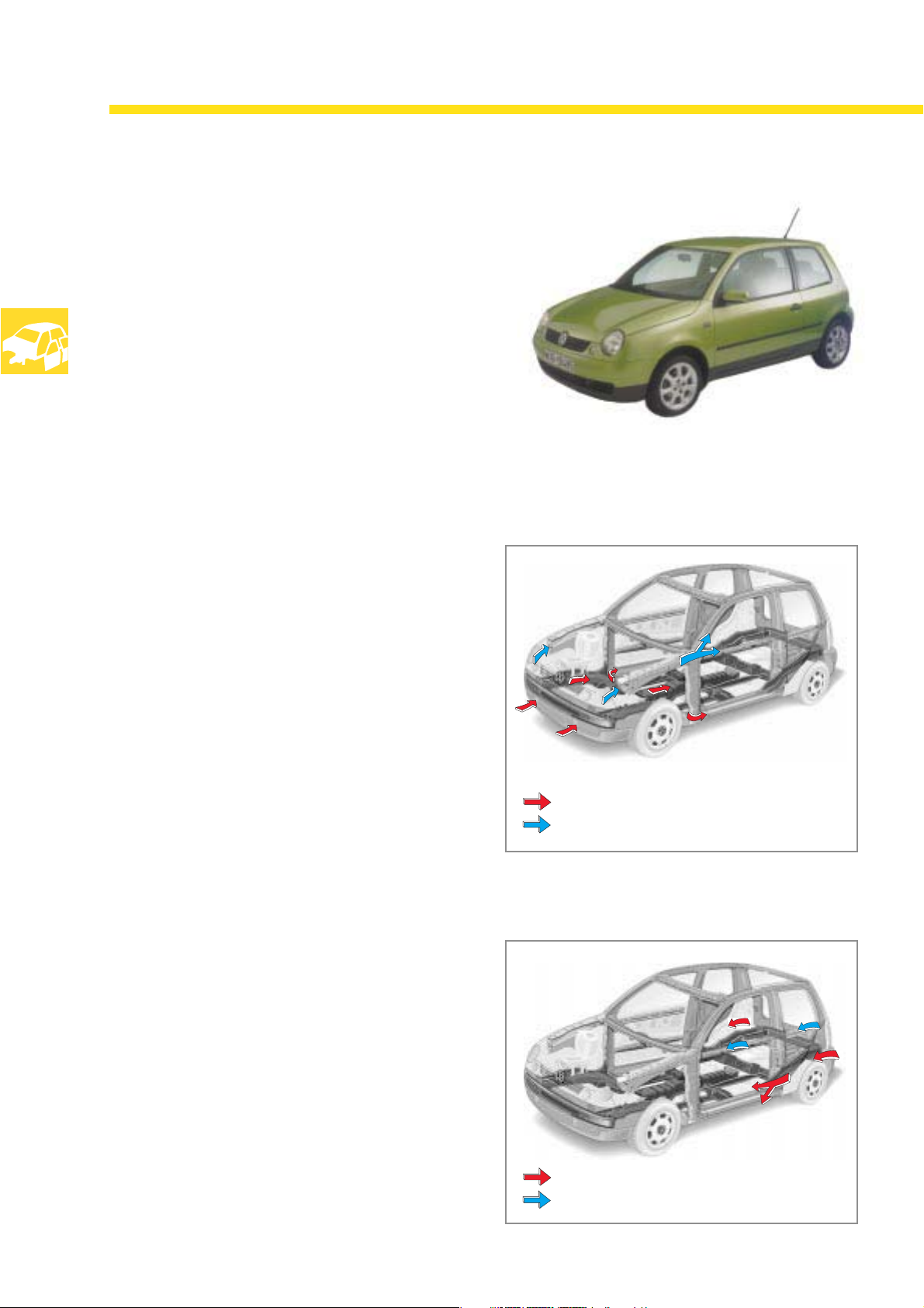
Body
Development
of the safety bodyshell
The blueprint for development of the
LUPO's body was the Polo ‘95.
A key development goal was to design a body
whose occupant cell offers a high level of
dimensional stability in crash situations.
During a head-on collision,
the impact energy is absorbed
via 2 crash planes:
SSP 201_021
In the 1st crash plane, the side re-inforcement in
the doors located directly behind the bumper
cover, transmits the impact energy to the side
members. The energy is then distributed evenly
to the centre tunnel and re-inforced side
members.
In the 2nd crash plane, the wheelhouse side
members transfer the impact energy via the door
re-inforcements to the rear end.
In the event of a rear collision,
the side re-inforcement in the doors behind the
bumper cover transmits the force to the side
members.
The body side panel which is almost fully
enclosed on the inside helps to absorb more
energy.
= 1st crash plane
= 2nd crash plane
SSP 201_046
10
= 1st crash plane
= 2nd crash plane
SSP 201_046
Page 11
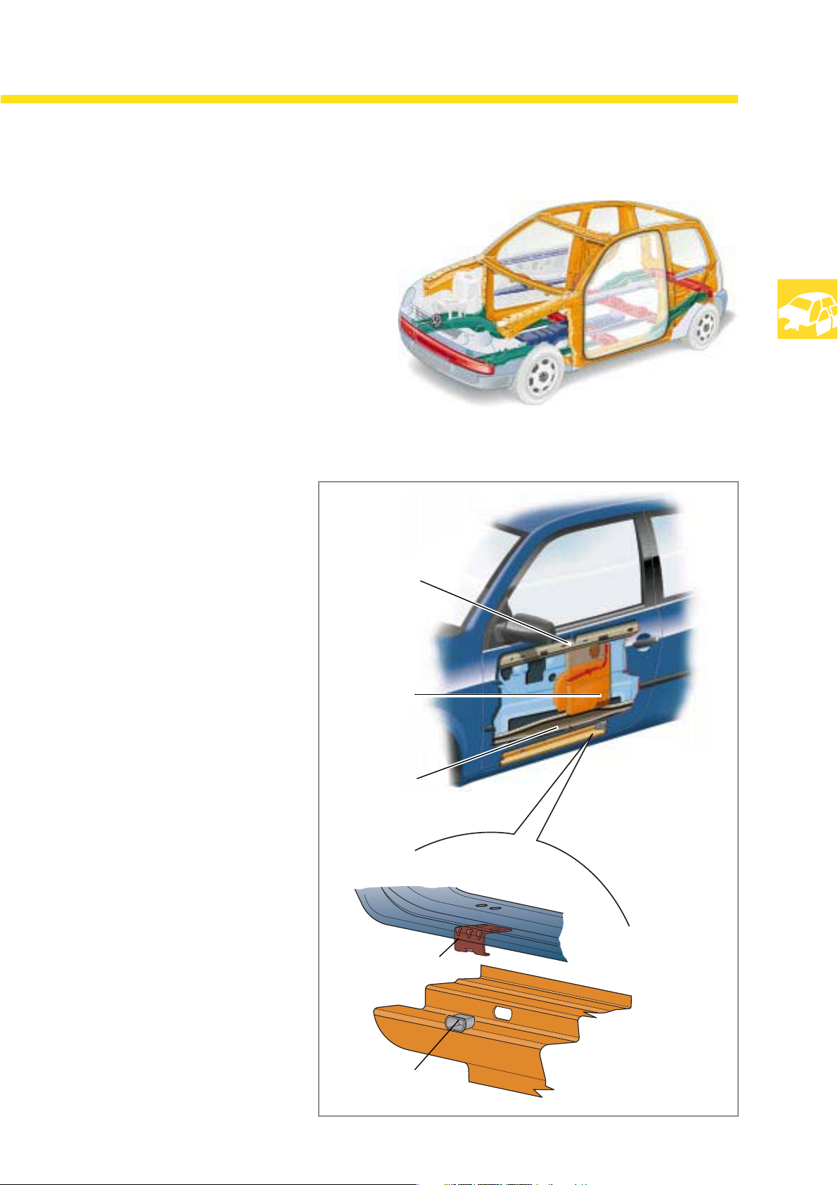
In the event of a side impact,
the re-inforced A- and B-pillars, the strong side
members and the almost fully integrated inner
panel of the door minimise deformation of the
occupant cell.
The side impact re-inforcement in
the door, the door-glass channel reinforcement and the intermediate
padding produce an optimal barrier
against the force of impact.
Door-glass
channel re-
inforcement
SSP 201_024
The closed door is securely
anchored to the side member by
means of a bracket on the
underside. During a side impact, it
prevent the door from intruding into
the occupant cell.
Padding
Side
impact
reinforce
ment in
the door
Bolt-on
bracket
Plastic guide
SSP 201_026
SSP 201_025
11
Page 12
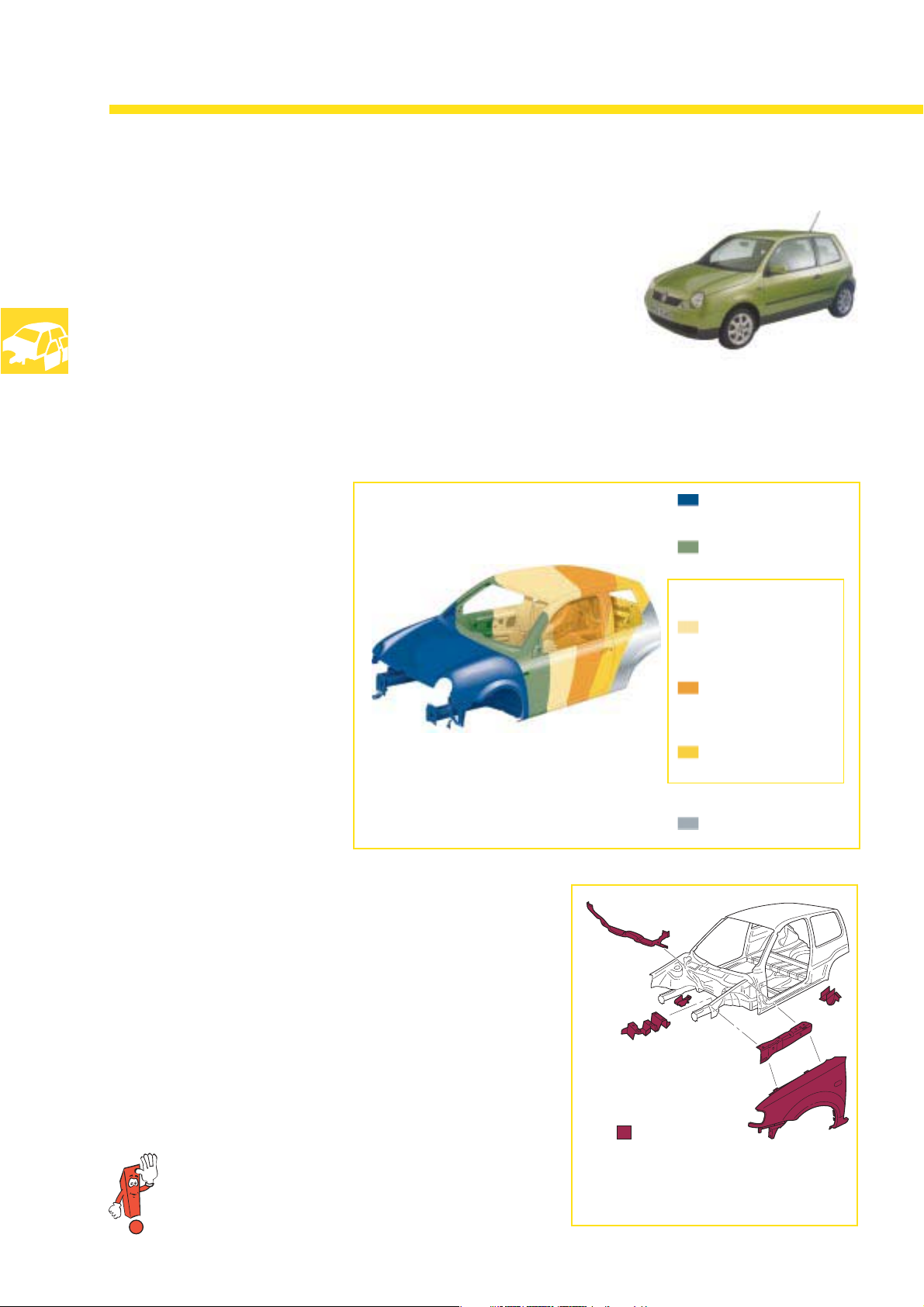
Body
The body of the
LUPO has
features which surpass the norm for this class:
-
Long-term corrosion protection
-
Fully-galvanised body
Crash performance in acordance with VW's
-
safety standard
Modular design
-
Narrow ioints
-
Paintwork structure
and corrosion protection
Environmentally friendly, waterdilutable paints are:
The cathodic cataphoresis,
-
filler, top coat (met. base
coat,
solid base coat )
Galvanised sheet steelLegend:
Zinc phosphatisation
Water based
Cathodic
immersion
cataphoresis
Filler coat
All outer panel are
-
electroplated.
All inner panels are hot-dip
-
galvanised.
SSP 201_027
High-strength body panels
are also used in the LUPO.
They are not as thick as conventional body panels and, as a
result, weigh less but are stronger.
High-strength body panels have the task of absorbing and
distributing energy during a crash in a more controlled
manner.
They absorb vibrations at the rear axle mount.
You can find detailed information regarding
high-strength sheet-metal panels in Self-Study
Programme No. 200.
Top coat
Clear coat
High-strength body
panels
SSP 201_028
12
Page 13
F
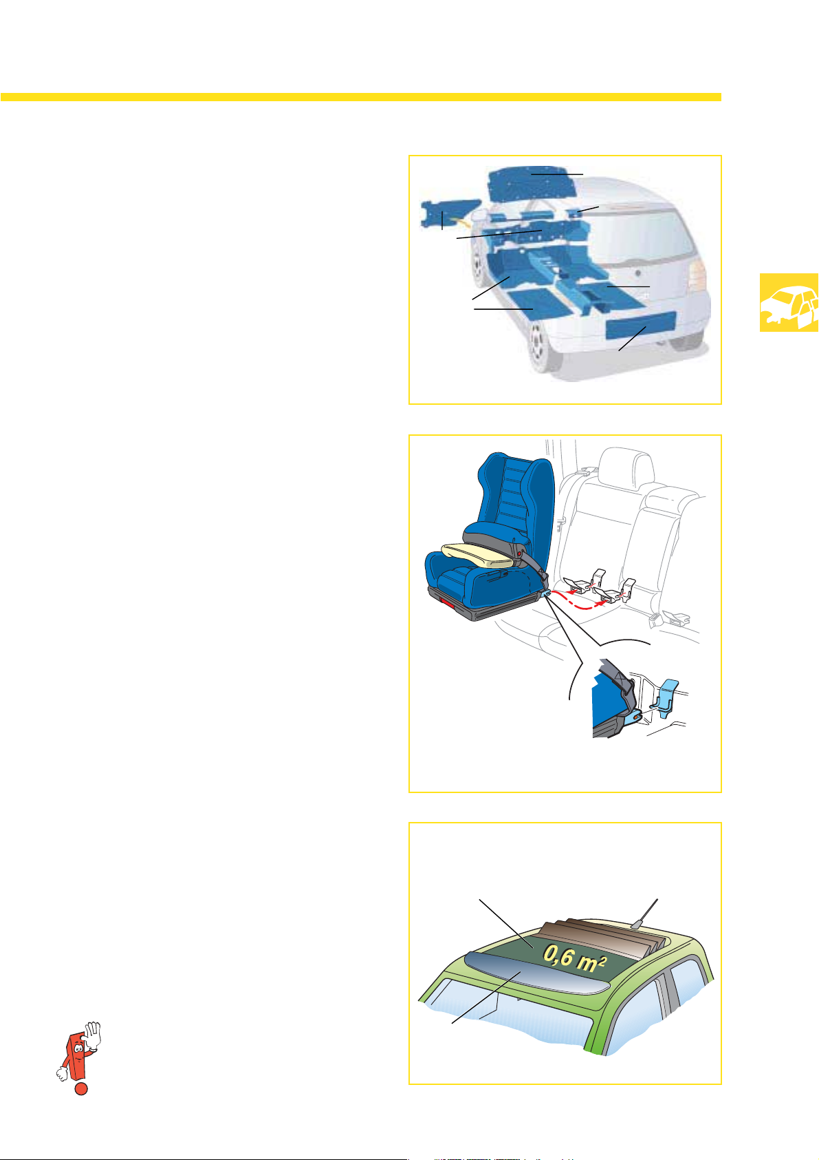
Bitumen-based heat-shrinkable and adhesive
foils of various thickness as well as felt parts and
carpeting are used for soundproofing purposes.
The adhesive foils absorb the vibrations which
occur in various areas of the body. Felt parts
absorb noise by interrupting the sound wave.
The Isofix child safety seat fastening
is fitted in the LUPO as standard.
There are 4 retaining eyelets below the rear
seats, which make it possible to install two child
safety seats with the Isofix fastening system. The
retaining eyelets are welded to the floorpan
assembly and hold the child safety seat securely
during a crash.
F
B
FBFelt parts
Heat-shrinkable/
adhesive foils
B
B
F
SSP 201_029
The electric fabric sliding roof
In addition to the electrically-operated glass
sliding/tilting roof, an electrically-operated
fabric sliding roof is also available for the LUPO.
The roof spoiler allows the vehicle to be driven
without any draught and quietly with the sunroof
open, even at high speed.
The electric fabric sliding roof is identical
to the sunroof used in Polo model ‘95.
SSP 201_030
Fabric sliding roof
Sunroof opening
Roof spoiler
SSP 201_031
13
Page 14
Body
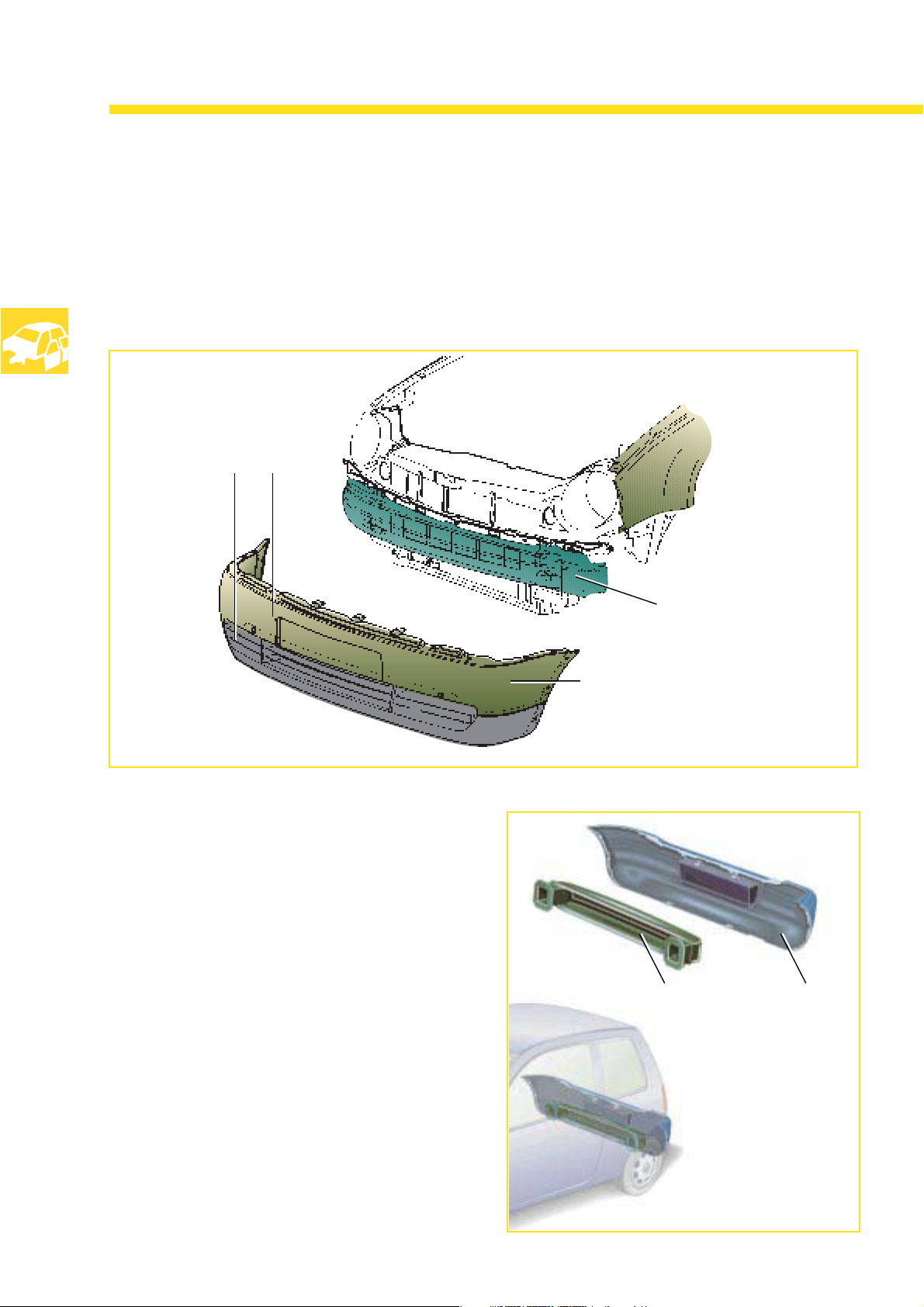
The front and rear bumpers
comprise a side re-inforcement in the doors and
a bumper cover.
Front
The front bumper cover
comprises 2 components
The front and rear bumper covers are capable of
absorbing impact energy at speeds of up to 4
kph without damage.
Higher impact speeds of up to approx. 15 kph
are absorbed by the side re-inforcement in the
doors without deformation of the side members.
The side members only become deformed as a
result of a severe impact.
Side re-inforcement in
the doors
The upper section is painted
in the body
colour
Rear
Side re-
inforcement in the
doors
SSP 201_032
Bumper
cover
14
SSP 201_034
Page 15
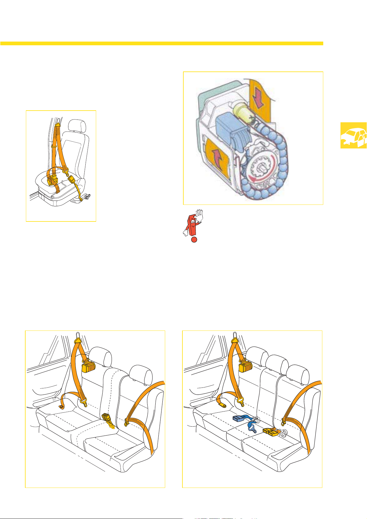
The restraint system
and the airbags
Seat belts
Front:
They have ball-type
tensioners which are
fired both
mechanically and
pyrotechnically.
SSP 201_171
SSP 201_170
For more detailled information on the belt
tensioners, please refer to
Self-Study Programme No. 192.
3-point seat belt concepts for the rear seats
Standard equipment The 5-seater version is also equipped with a lap
belt for the middle seat.
SSP 201_173SSP 201_172
15
Page 16
Body
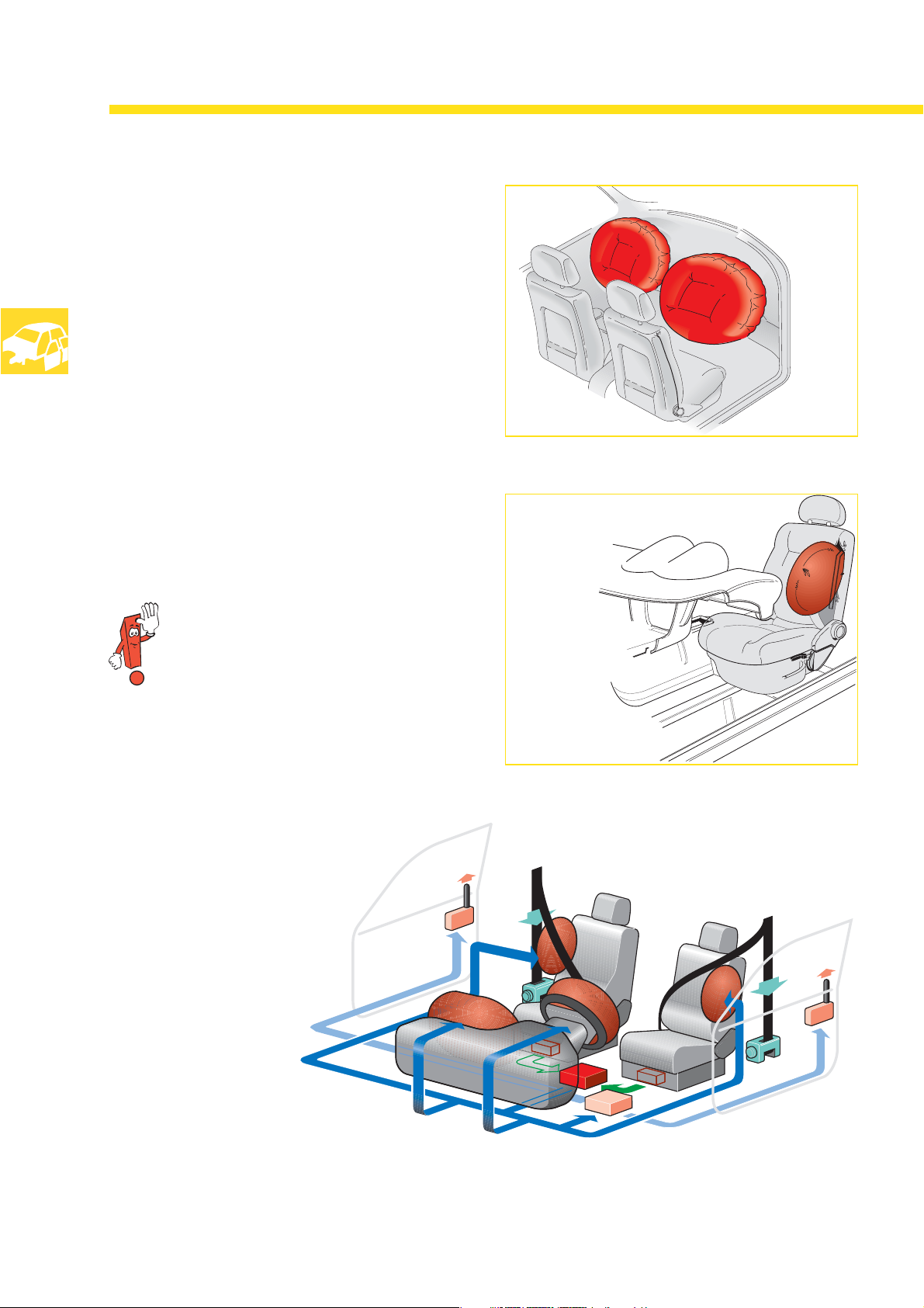
The front airbags
have a volume of 57 litres for male/female
drivers
and a volume of 95 litres for the front passenger.
At production launch, a 120-litre front
passenger's airbag will be used. It will be
identical to the airbag used in the Golf ’98.
The 120-ltr. front passenger's airbag cannot be
replaced by the 95-ltr. airbag, therefore it can
only be replaced in accordance with the original
equipment level.
The side airbags
SSP 201_174
have a volume of 12 litres.
All gas generators contain acid-free propellant.
The function of the restraint system
during severe accidents
The restraint system prevents
contact occurring between the
shoulder and head area with
the steering wheel or dash
panel insert.
SSP 201_175
16
Once the firing threshold
is attained, the airbag
control unit transmits the
"Open central locking (CLS)" signal
to the CLS control unit.
SSP 201_176
Page 17
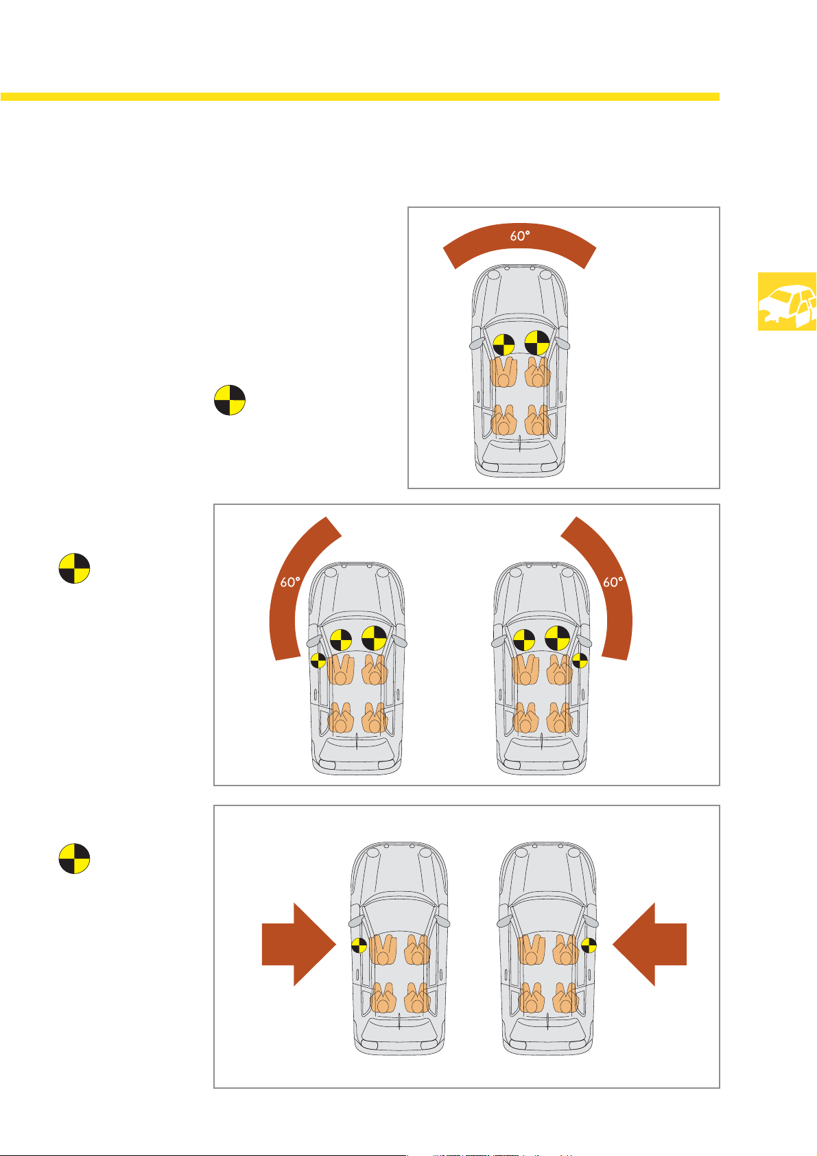
The airbag system
As of a defined degree of accident severity and
the
the associated delay period, the appropriate
airbags are triggered depending on the impact
side and the angle of impact.
Head-on collision
The driver's and front
passenger's airbags
are triggered.
Side/head-on
collision
SSP 201_102
The driver's, front
passenger's and side
airbags are triggered.
Side impact
Only the side airbag
which is actually
required to protection
the vehicle's
occupants is triggered.
This considerably
reduces repair costs
after an accident.
SSP 201_103
SSP 201_104
17
Page 18

Engines
The engine-gearbox combination
Engines Gearbox
1.0-ltr.
37 kW petrol engine with camshaft in block
1.4-ltr.
16V 55 kW petrol engine
5-speed
manual
gearbox
085
4-speed
automatic
gearbox
001
5-speed
manual
gearbox
002
18
1.4-ltr.
16V 74 kW petrol engine
1.7-ltr.
44 kW SDI engine
1.0-ltr.
37 kW rocker lever petrol engine
Page 19

The 1.0-ltr. 37 kW petrol engine
is an advanced version of the proven 1.0-ltr.
aluminium engine with the camshaft in block
SSP 201_038
Features of the engine mechanicals are:
Aluminium cylinder crankcase with press-fitted
•
cast iron cylinder liners
Cylinder head with single overhead camshaft•
Bucket tappets with hydraulic adjusters•
Features of the engine management system
are:
Motronic MP 9.0 (refer to Self-Study
•
Programme No. 168)
Sequential injection•
Rotating ignition voltage distribution•
Selective knock control•
Conforms to exhaust emission standards EU III
•
and D3
Power output
crankshaft
80
70
60
40 120
30
20
10
0
1000 3000 5000
0
2000 4000 6000
Engine speed rpm
Torque
Nm
200
180
160
14050
100
80
60
40
SSP 201_041
Specifications
Engine code “ALL“
4-cylinder inline engine
Valves per cylinder 2:
Displacement
Bore 70.6 mm
Stroke 67.1 mm
Compression ratio 10.5 : 1
Max. output 37 kW
:
:
:
:
:
999 cm
3
at 5000 rpm
Max. torque 86 Nm at
:
3000 to 3600 rpm
Engine management Bosch Motronic
:
MP 9.0
Fuel type unleaded 95 RON
:
Knock control allows the engine to be operated
alternatively with unleaded 91 RON fuel but with
a slight reduction in power output and torque.
19
Page 20

Engines
The new engine generation:
Overview
The 1.4-ltr. engines described on the
following pages belong to a new generation
of petrol engines.
All have:
a new cylinder head with valve activtion
•
via roller cam follower
Aluminium cylinder block•
•
An engine speed sensor which is
integrated in the flange for the crankshaft
sealing ring at the flywheel end
static high-voltage distribution•
All conform to
exhaust emission standards EU III
and D3.
Cylinder head
The camshafts are mounted in the
camshaft housing. The camshaft housing
also acts as the valve cover.
SSP 201_049
SSP 201_044
Camshaft
Roller cam follower
20
The valves and hydraulic support elements
are fitted in the cylinder head.
The roller cam follower engages in the
support element and abut the end of the
valve stem.
Illustration of the 16V engine
Camshaft
Hydraulic
support
element
SSP 201_050
Page 21

Valve activation
by roller cam follower
Conventional cam follower
The roller cam follower
Slip face
Counterbearing
(adjustable)
SSP 201_052
Roller running
in needle
bearings
The cam glides over the slip face of the cam
follower. As a result, high friction losses occur
and the cam follower is subjected to mechanical
stress.
Valve clearance is adjusted manually via the
adjustable counter-bearing.
The roller cam follower (depressed)
Hydraulic
support
element
SSP 201_053 SSP 201_054
The cam of the roller cam follower rolls off a
roller running in needle bearings.
The cam stroke is transmitted to the valve stem
with minimal friction loss.
Oil duct
The hydraulic support element replaces the
manually adjustable counter-bearing. It acts as
the pivot for the roller cam follower and assumes
the task of automatic valve clearance adjustment.
Lubrication and filling are performed via an oil
channel in the cylinder head.
For more detailled information, please
refer to Self-Study Programme No. 196.
21
Page 22

Drive units
The 1.4-ltr. 16V 55 kW petrol engine
SSP 201_043
Features of the engine mechanicals:
Aluminium cylinder crankcase•
Press-fitted cast iron cylinder liners•
Cylinder head with roller cam followers•
Secondary belt drive•
Primary catalytic converter integrated in the
•
exhaust manifold
Conforms to exhaust emission standards EU III
•
and D3
Power output
kW
80
70
60
40 120
30
20
10
0
1000 3000 5000
0
2000 4000 6000
Engine speed rpm
Torque
Nm
200
180
160
14050
100
80
60
40
SSP 201_045
Specifications
Engine code “AKQ“
4-cylinder inline engine
Valves per cylinder 4:
Displacement
Bore 76.5 mm
Stroke 75.6 mm
Compression
:
1390 cm
:
:
:
10.5 : 1
3
ratio
Max. output 55 kW
:
at 5000 rpm
Max. torque 128 Nm
:
at 3300 rpm
Engine management Magneti Marelli 4AV:
Fuel type unleaded 95 RON
:
22
For more detailed information, please
refer to Self-Study Programme No. 196.
Knock control allows the engine to be operated
alternatively with unleaded 91 RON fuel but with
a slight reduction in power output and torque.
Page 23

The 1.4-ltr. 16V 74 kW petrol engine
The basic engine is the 1.4-ltr.-16V 55 kW petrol
engine.
SSP 201_147
Power output
kW
80
70
Torque
Nm
200
180
The key differences compared to the
1.4-ltr. 16 V 55 kW petrol engine
Stronger pistons•
Cylinder head with larger intake
•
and exhaust ducts
Modified camshaft timing•
Modified intake module•
Modified exhaust system•
Aluminium oil sump for increased rigidity of
•
higher-performance engine
conforms to exhaust emission standards EU III
•
and D3
Specifications
Engine code “ANM“
4-cylinder in-line engine
Valves per cylinder 4:
60
40 120
30
20
10
0
1000 3000 5000
0
2000 4000 6000
Engine speed rpm
For more detailed information, please
refer to Self-Study Programme No. 196.
160
14050
100
80
60
40
SSP 201_048
Displacement
Bore 76.5 mm
Stroke 75.6 mm
Compression ratio 10.5 : 1
Max. output 74 kW
:
1390 cm
:
:
:
:
3
at 6000 rpm
Max. torque 128 Nm
:
at 4500 rpm
Engine management Magneti Marelli 4 AV:
Fuel type unleaded 98 RON
:
The knock control also allows the engine to be
operated alternatively with unleaded 91 RON
fuel with a slight reduction in power output and
torque.
23
Page 24

Drive units
the 1.7-ltr. 44 kW SDI diesel engine
e
h
t
s
i
Features of the engine
mechanicals:
Diesel direct injection engine•
Th
r.
t
l
-
9
.
1
d
e
m
r
e
t
n
i
e
h
t
s
i
h
t
i
w
DI
T
i
t
f
a
h
s
e
t
a
e
n
i
g
n
e
c
i
s
a
b
e
Naturally aspirated engine•
•
Displacement was reduced
to 1.7-ltr. from 1.9-ltr. by
modifying the crankshaft
stroke.
The external crankcase
B
i
t
c
e
j
n
i
p
m
u
p
n
o
r
to
u
b
i
r
t
s
i
d
h
c
s
o
•
breather has been deleted.
•
The gases in the crankcase
are diverted into the intake
duct via the oil return ducts
and the valve cover.
SSP 201_055
•
Two-stage EGR valve for
better metering of the
exhaust gas recirculation
conforms to exhaust emission
•
standards EU III
Power output
kW
80
70
60
40 120
30
20
10
0
1000 3000 5000
0
2000 4000 6000
Engine speed rpm
Torque
Nm
200
180
160
14050
100
80
60
40
Specifications
Engine code “AKU“
4-cylinder inline engine
Valves per cylinder 2:
Displacement 1.7-ltr.
Bore 79.5 mm
Stroke 86.4 mm
Compression ratio 19.5 : 1
Max. output 44 kW
:
:
:
:
:
at 4200 rpm
Max. torque 115 Nm
:
at 2200-3000 rpm
Mixture preparation Bosch distributor
:
injection pump
and electronic control
unit EDC 15
24
SSP 201_057
Fuel type min. 45 CN
:
Page 25

The 1.0-ltr. 37 kW petrol engine
is an improved version of the 1.3-ltr. engine fitted
in the Skoda Felicia.
( for certain markets only )
SSP 201_037
Features of the engine mechanicals are:
The valve is driven via a camshaft in block
•
(ohv), tappets, push rods and rocker levers
The cylinder crankcase is made of die cast
•
aluminium
“wet-type" cast iron cylinder liners •
The crankshaft runs in 3 bearings•
Features of the engine management system
are:
Multipoint injection•
Static high-voltage distribution•
Conforms to exhaust emission standards EU III
•
and D3
Power output
kW
80
70
60
40 120
30
20
10
0
0
1000 3000 5000
For more detailed information, please
refer to Self-Study Programme No. 203.
2000 4000 6000
Engine speed rpm
Torque
Nm
200
180
160
14050
100
80
60
40
SSP 201_039
Specifications
Engine code “AHT“
4-cylinder in-line engine
Valves per cylinder 2:
Displacement
Bore 72 mm
Stroke 61.2 mm
Compression ratio 10 : 1
Max. output 37 kW
:
:
:
:
:
997 cm
3
at 5000 rpm
Max. torque 84 Nm
:
at 3250 rpm
Engine management Siemens Simos 2P:
Fuel type unleaded 95 RON
:
Knock control allows the engine to be operated
alternatively with unleaded 91 RON fuel with a
slight reduction in power output and torque.
25
Page 26

Power transmission
The 5-speed manual gearbox 085
is fitted in petrol engines with overhead camshaft
s
e
t
d
n
a
d
e
i
Tr
n
i
d
e
t
t
i
f
o
s
l
a
synchronisation
1st and 2nd gear
R
u
c
le
e
s
eve
n
to
s
r
n
y
m
r
Po
Double
e
s
ro
h
c
low
e
l
g
-
c
d,
e
t
e
h
t
5
9
˚
o
s
i
r
a
e
d
e
s
i
n
n
tio
o
m
m
is
n
a
h
and in the diesel engine.
The total transmission ratio
matched to the installed
engine version is spread
by means of different gear
ratios and final drive ratios.
The gearbox is assigned to
the engine via the gearbox
code.
The gear selection system
Gear engagement is via a gate selector lever
and gear selector cable.
Gate selector cable
SSP 201_062
Gear selector
cable
26
SSP 201_063
Thanks to the selector cables, the swinging
motion of the engine only has a minimal effect
on the gear lever. As a result, gears can be
selected with greater precision.
Page 27

The 5-speed manual gearbox 002
is exclusive with the 1.0-ltr. rocker lever petrol
engine “AHT“, an improved version of the 1.3-ltr.
engine in the Skoda Felicia.
( for certain markets only )
Technical features:
5-speed manual gearbox•
Reverse gear is
•
unsynchronised
Two-part aluminium
•
gearcase
•
The end cover and the
engine suspension have
been modified.
Common oil filling for
•
gearbox and final drive
Final drive via drive shaft
•
flanges
Trie
d
a
n
d
te
ste
d
g
e
a
rb
ox
a
d
o
p
te
d
fro
m
th
e
C
a
d
d
y
p
icku
p
A gear change
is performed by a selector rod.
SSP 201_060
Selector rod
Guide
Selector
housing
The gear lever is mounted on
two bearing bolts in a guide in
floating configuration. A cable
pull transmits the relative
movement of the engine to the
guide. This reduces oscillation
at the gear lever.
The gears can therefore be
engaged with greater
precision.
Cable pull
SSP 201_061
27
Page 28

Power transmission
The 4-speed automatic gearbox 001
is available for 1.4-ltr. 16V 55 kW petrol engine
e
h
t
s
i
“AKQ“.
P
h
t
n
i
t
c
e
l
E
o
c
d
e
e
p
s
-
4
5
9
'
o
l
Po
e
y
l
l
a
c
i
n
ro
d
e
l
l
ro
t
n
ox
b
r
a
e
g
d
e
t
t
i
f
o
s
l
a
y
l
s
u
o
i
rev
Gear selection
The individual drive positions, the parking lock
and neutral are selected mechanically with the
gate selector lever.
SSP 201_064
Technical features:
Ravigneaux planetary gear•
•
Torque converter
with integrated lock-up
clutch
•
Solenoid valves at the valve
body for electro-hydraulic
control
•
Common oil supply
for planetary gear and
final drive
in out
The control unit records the
incoming sensor signals
during vehicle operation,
evaluates these signals and
activates the individual
solenoid valves.
The integrated dynamic shift
program automatically selects
the "Eco" shift characteristic or
"Sport" shift characteristic.
SSP 201_065
For more detailed information, please refer to in
Self-Study Programme No. 176 “4-speed
Automatic Gearbox 001“ .
28
Page 29

The fuel tank
of the LUPO is located in the crash-protected
area in front of the rear axle.
It has a volume of 35 litres.
Petrol engines
The activated charcoal canister
is located at the front righthand side of the vehicle.
The activated charcoal
absorbs fuel components from
fuel vapours.
Fuel system
P
rove
n
E
le
ctric
in
te
rio
r
ta
n
k p
u
m
p
G
ra
vity
p
re
f va
m
ssu
lve
te
d
ch
a
re
lie
Activa
syste
Quick-release couplings are used
for installing the fuel pipes.
rco
re
a
l ca
n
iste
r
SSP 201_051
Act. char. canister
SSP 201_059
The fuel gauge sender is attached to
the fuel pump housing.
SSP 201_047
Quick-release
couplings
Fuel pump
Sender
Diesel engines
Diesel-engined vehicles do not require a fuel
pump or activated charcoal canister. The fuel
gauge sender, in combination with the intake
manifold
SSP 201_058
for the intake, form a single unit. The fuel pump
is an integral part of the distributor injection
pump.
29
Page 30

Running gear
The running gear
of the LUPO is identical to the Polo’95.
s
le
u
d
o
m
n
sio
n
e
sp
u
S
ro
g
e
th
co
la
u
d
o
m
p
u
To
m
r sy
Fro
s
r
S
p
i
risin
e
t
n
n
o
re
ste
e
t
a
g
m
g
n
i
r
e
l
x
a
m
a
e
b
e
l
x
a
r
The running gear has been adapted to the
LUPO, making allowance for driving safety and
driving comfort.
The following pages will present you
with the following items:
•
The steering
•
The front axle
•
The rear axle
•
The brakes
•
The traction control systems
SSP 201_080
30
Page 31

The steering
comprises a safety steering column which is
height-adjustable and a mechanical steering
gear.
The safety steering column
m
m
9
3
1
5
0
SSP 201_066
S
u
sp
e
n
sio
n
m
o
d
u
le
s
o
d
u
la
r syste
m
g
n
n
i
c
a
l
g
e
a
r
e
e
r
i
n
g
th
co
m
p
risin
g
Pow
g
e
M
s
ro
u
p
m
S
a
fe
ty
ste
e
rin
co
lu
m
e
c
h
a
t
e
e
r
i
n
g
e
r
s
t
a
r
e
G
The safety steering column can be
compressed by up to 150 mm during
m
m
a crash. This reduces the injury risk
for the driver.
Power steering
Depending on performance and wheel size, the
LUPO is equipped with power steering.
The two track rods for
power steering and
mechanical steering
are adjustable.
SSP 201_067
31
Page 32

Running gear
The front axle of the LUPO
comprises suspension struts and wishbones. The
suspension struts are bolted to the wheel bearing
housing and the wishbones are bolted to the
subframe by rubber mountings.
e
th
m
o
s fr
le
u
d
o
m
n
sio
n
e
sp
u
S
u
ro
G
Wh
la
u
d
o
m
p
s
n
e
p
s
u
S
s
ra
f
b
u
S
a
e
b
l
e
e
o
h
m
ste
r sy
n
o
i
t
u
r
t
e
m
g
n
i
r
g
n
i
s
u
For more detailed information regarding this axle
in respect of castor, shock absorption
characteristics and the track-stabilising kingpin
offset, please refer to Self-Study Programme No.
166.
32
SSP 201_068
The Lupo with power
steering has an antiroll bar on the front
axle.
Anti-roll bar
SSP 201_069
Page 33

The rear axle
is a torsion beam axle.
S
co
Th
u
sp
e
n
sio
n
m
o
d
u
le
m
p
risin
g
G
ro
u
p
m
e
s
o
d
u
la
r syste
m
Toe and camber design are defined by design
and are non-adjustable. For vehicle alignment,
the ascertained values can only be compared
with the nominal values in the Workshop
Manual.
Shock absorbers
SSP 201_070
To
rsio
n
b
e
e
r a
e
a
x
le
n
d
e
l b
e
a
rin
ra
tio
n
re
a
S
e
co
w
h
g
e
n
Springs and dampers
are positioned separately.
m
-
g
SSP 201_072
SSP 201_083
The bonded rubber bushes of the rear axle
have been fitted rotated through 45°.
This reduces noise transmission from the
road to the body.
33
Page 34

Th
e
Running gear
The brake system
The standard equipment comprises:
rd
a
d
n
sta
re
s a
m
ite
g
in
llow
fo
e
t
n
e
m
ip
u
q
ll ve
a
in
ra
b
s:
icle
h
l
a
n
o
g
a
i
D
u
d
k
ra
b
ra
B
d
-
d
a
Lo
re
u
s
s
re
p
e
k
t
i
l
p
s
t
i
u
rc
i
c
-
l
a
m
e
t
s
y
s
e
vo
r
e
s
e
k
t
n
e
d
n
e
p
e
re
r
to
a
l
u
g
ventilated front disc brakes•
self-adjusting rear drum brakes•
For added active safety, the anti-lock braking
system ITT Mark 20 IE is available with electronic
brake pressure distributor.
34
SSP 201_073
Page 35

The front brakes
Ventilated
disc brakes
up to 55 kW
dia. 239 mm x 18 mm
SSP 201_074
as of 74 kW
dia. 256 mm x 20 mm
SSP 201_071
The rear brakes
Drum brakes to 55 kW Disc brakes for 74 kW and above
dia. 180 x 30 mm
without ABS
dia. 200 x 40 mm
with ABS
SSP 201_075 SSP 201_076
dia. 232 x 9 mm
Alu. sliding caliper
35
Page 36

Running gear
The
ElectronicStabilityBrakeSystem
improves track stability and steerability when the
vehicle is being braked by activating the brakes
selectively.
ESBS is an improved software in the
ITT Mark 20 IE control unit.
It utilises the sensors and actuators from the antilock braking system system.
SSP 201_077
SSP 201_078
Understeer
If a vehicle is braked heavily in a corner, the
wheel location forces acting on the front wheels
are reduced.
As the vehicle has forwards momentum, its
pushes towards the outer edge of the corner
over the front axle.
This driving situation is termed “understeer“.
In vehicles with ESBS, the ABS control unit
recognises this driving situation and responds by
altering the speeds of the individual wheels as
appropriate.
The anti-lock braking system reduces the brake
pressure applied to the front axle. This increases
the wheel location forces and the vehicle retains
its directional stability.
36
SSP 201_079
Page 37

SSP 201_081
Oversteer
If the vehicle is steered into a corner too sharply
at high speed and if the brakes are applied
heavily, the rear will break away towards the
outer edge of the corner.
This driving situation is referred to as “oversteer“.
The ABS control unit recognises this situation and
responds by reducing the speed of the rear
wheels and reducing the brake pressure applied
to the wheels on the inside of the corner. This
increases the wheel traction forces acting on the
wheels on the inside of the corner and the vehicle
rear end retains its directional stability.
SSP 201_082
Malfunctioning of the ESBS can neither be
diagnosed nor repaired, because a vehicle's
driving dynamics cannot be reproduced with
workshop facilities.
37
Page 38

Electrical system
Decentralised vehicle electrical
system
The layout of the electrical system is
decentralised, i.e. the basic component parts of
the electrical system are located at different
fitting locations.
The main components are:
Main fuse box at the battery•
•
Relay carrier, coupling station, potential
distributor and fuse holder behind the dash
panel insert
Coupling station at A-pillar,
•
left and right
Vehicle-specific wiring harness•
Diagnosis plug•
Coupling station
A-pillar
Main fuse box
Diagnosis plug
Coupling station at A-pillar
Fuse holder
Relay
carrier
Battery
38
Bracket at en-gine
bulkhead
Pot. distributor
Coupling station
SSP 201_095
Page 39

The components of the
decentralised vehicle electrical
system
SSP 201_090
Main fuse box
Here, the electrical system is protected by fuses
directly behind the battery.
•
The alternator, cabin power supply, glow plug
system and the air conditioning system are
protected by metal fuses.
The ABS system and the radiator fan are
•
protected by micro-fuses (Little Fuse).
In the current flow diagram, the fuses positioned
here have the code designation “SA“.
100 19
1515153015151515151515151515303020
167
100 19
1515153015151515151515151515303020
Relay carrier
167
Used for mounting the relays for standard
equipment and optional extras.The relay carrier
is fixed by two retaining lugs.
SSP 201_091
Coupling station below relay carrier
The connections to the vehicle electrical system
are made in the coupling station by means of
colour-coded and mechanically coded
connectors (e.g. engine compartment, dash
panel insert). The potential distributor is located
on the left next to the coupling station (threaded
terminal, terminal 30).
SSP 201_092
39
Page 40

Electrical system
The components of the
decentralised vehicle electrical
system
Fuse-holder
100 19
1515153015151515151515151515303020
167
Two different fuses are used to protect the
electrical circuit.
Mini-fuse rated for max. 15A-
Micro-fuse (Little Fuse) rated for over 15 A-
SSP 201_093
This combination offers the following
advantages:
More fuses within the same construction space-
More electrical circuits protected by individual
-
fuses
In the current flow diagram, the fuses positioned
here have the code designation “SB“.
SSP 201_097
SSP 201_087
Coupling station at A-pillar
The connections to the doors, e.g. loudspeakers,
central locking and power windows, are located
in this coupling station.
Diagnosis plug
Fitting location: in dash panel insert, behind
oddments tray.
40
Page 41

The fitting locations of the control
units
Airbag control unit
on gearbox tunnel
Engine control unit
Automatic gearbox
control unit
ABS control
unit
Control unit for
radiator fan
Control unit for
central locking/above
relay carrier
Control unit for
immobiliser/above fuseholder
SSP 201_094
41
Page 42

Electrical system
The dash panel insert
The distinctive design of the dash panel insert
comprises two instrument clusters.
The rev counter comprising:
- Fuel indicator
The speedometer comprising:
- Odometer and trip recorder
9
8
0
1_
0
2
P
S
S
- Coolant temperature display
- Digital clock
- and warning lamps
40
30
20
50
60
10
0
Setting buttons for digital clock Reset button for trip recorder and
- Service Interval Display
- Indicator
- and warning lamps
70
SSP 201_098
Service Interval Display
42
Technical features:
•
LEDs are used exclusively for illumination and
as warning lamps.
Blue instrument lighting with luminous red
•
pointers.
•
The analogue displays (rev counter, speedometer, fuel gauge and coolant temperature)
are activated by stepping motors with
software-controlled damping.
Connected to vehicle electrical system by
•
means of a 32-pin connector.
The same version of the dash panel insert is
•
used for all model variants.
The Lupo has the same self-diagnosis (address
•
word 17) as in the Polo ‘98.
Page 43

The immobiliser
The immobiliser has a separate control unit
which is equivalent to the 2nd generation in
design and function and comprises an additional
variable code. The control unit is behind the dash
panel insert via the fuse holder.
The self-diagnosis function (address word 25) is
identical to the POLO ‘98.
Functional description:
After turning on the ignition, the transponder
transmits a fixed code via the reader coil to the
immobiliser control unit. If this code matches the
code stored in the immobiliser control unit, a
random number generator generates a variable
code. This variable code is transmitted to the
transponder in the car key fob. A secret
arithmetic operation is now started in the
transponder and in the immobiliser control unit.
The transponder transmits its result to the
immobiliser control unit which recognises the
correct car key by comparing this result with its
own result.
A variable code is then cross-checked between
the immobiliser control unit and engine control
unit. Once a match has been established, the
vehicle is ready for operation.
Engine control unit
Transponder
Reader coil
Immobiliser control unit
SSP 201_099
43
Page 44

Electrical system
The central locking system
In vehicles that are also equipped with power
windows, a control unit is integrated in the
The central locking system, in combination with
manual window lifters, is available as an
optional extra. The motors for central locking are
activated directly by the central control unit.
window lifter motor for operation and force
limitation. With this version also, the motors for
the central locking and window lifters are
activated directly by the central control unit.
The central locking comprises the following
functions:
•
Electric motor operated central locking
system with SAFE function for locking the
doors and tailgate.
Doors are locked and unlocked with interior
•
•
Convenience opening of the power windows
as well as convenience locking of the window
lifters and sliding/tilting roof is possible via
the door lock cylinder.
Self-diagnostic capability (address word 35).•
Lock - Unlock button
Interior light and boot light control.• Anti-theft warning system with radio-wave
•
remote control as an option
•
The airbag control unit unlocks the doors if it
recognises that the vehicle has been involved
in a crash.
Window lifter motor
and control unit
Contact switch for antitheft warning system
(option)
Tailgate actuator motor
Alarm signal horn
(option)
Window lifter motor with
control unit
Operating unit
Central module
SSP 201_096
44
Page 45

Radio generation ‘99
The
BETA
and
GAMMA
fundamentally revised from a technical
viewpoint and their design has been updated.
The alpha radio system is available with
unchanged technology and design.
.
radio systems have been
Control panel
The figures show the user interface of the
and
GAMMA
radio systems with removable
control panel.
Radio system
BETA
Radio system
GAMMA
BETA
SSP 201_124
SSP 201_118
The main new features of the
and
GAMMA
Display lighting in blue, button and
•
radio systems are:
buttons backlit in red.
•
Optionally available with
permanent or removable control
panel.
BETA
SSP 201_119
•
New menu adjustments,
e.g. balance or bass, and on-screen
menu assistance are possible.
•
The convenience anti-theft device
saves recoding the radio system,
e.g. after cutting off the power
supply for servicing.
Self-diagnostic capability•
45
Page 46

Electrical system
The
BETA
radio system
The new functional features are:
30-station memory•
•
The loudspeaker balance on the left and
right can be adjusted with the BAL (Balance)
button.
SSSSpeed-dependent volume adaption /
•
AA
GGGGAAAALLLLAA
Prepared for connecting CD changer •
•
Playback of calling or called party through
all loudspeakers while conducting a
telephone call.
Slider for removing the
control panel
The convenience anti-theft device
To commission the radio, the four-digit code
number of the electronic anti-theft device must
be entered.
When the NO contact is closed, a
communication link is established between the
radio and the dash panel insert via the selfdiagnosis wire (K wire).
If the supply is cut off, e.g. to carry out work on
the electrical system, the radio checks whether
the dash panel insert is the same as before
voltage cut-off after inserting the ignition key and
turning on the ignition.
SSP 201_127
If the radio recognises the dash panel insert, the
radio is again ready for operation without having
to reenter the four-digit code number a delay of
several seconds.
However, if the radio is fitted in another vehicle,
the four-digit code number must be re-entered.
46
Page 47

The
GAMMA
radio system
offers the following new features in addition to
the functional features of the
BETA
:
•
If the vehicle has a Highline dash panel
insert, the frequency and the station name
are displayed.
The above-specified combination is currently not
available for the LUPO.
•
With the TIM function, up to 9 traffic
announcements of a selected TP station can
be recorded automatically.
Max. total duration is 4 minutes.
When the radio is on, every traffic information
message is recorded as soon as TP appears in
the display. When the radio is off, record
mode can be activated by briefly pressing the
TIM button. The memory automatically stores
traffic information messages for a 24-hour
period.
Once this period of time has elapsed or when
the radio is switched on, the standby function
ends.
•
Due to programme content, e.g. classical
music or rock music, the various stations have
a different basic volume.
The radio adjusts the basic volume by
automatically adapting the volume, provided
that the stations have been programmed in
the station keys.
For more detailed information regarding the
subject of Radio Reception/Basics, please refer to
Self-Study Programme No. 147 “Radio Systems
´94“.
The CD player
The new CD player can be
combined with the
and
GAMMA
radio
BETA
systems.
The fitting location is
above or below the radio,
SELECT
depending on the vehicle
model.
To select CD player mode and
CD changer mode
The CD player can play back one music CD at a
time. The CD player is operated by means of the
radio buttons.
CD
CD IN
CD eject buttonSELECT button
CD CHANGERCD PLAYER
CD
SSP 201_125
The CD player can also be combined with a 6disc CD changer which has been optimised in
size.
47
Page 48

Heating, air conditioning
For heater and air conditioner operation in the
LUPO, two equipment variants are available:
a heater or-
a manually operated
heater and air conditioner
Heater
As in other models, too, fresh air/air
recirculation mode is possible for added
comfort.
Air recirculation mode can be switched on
and off with the air recirculation button
Air recirculation mode is switched off
automatically when the rotary switch for air
distribution is set to "Defrost".
The depressed air recirculation button
is released mechanically.
This keeps any moist cabin air, e.g. due to
wet clothing, away from windscreen.
Manual air conditioner
In the case of the manual air conditioning
system, the driver or front passenger
controls the interior climate. Air conditioning
mode can be switched on or off by pressing
the AC button (Air Conditioning).
SSP 201_106
SSP 201_107
48
The fresh air/air recirculation flap
isoperated by electric motor. All other flaps
are activated via Bowden cables.
An electronic high pressure sender
records the overall refrigerant pressure
curve.
SSP 201_108
SSP 201_109
Page 49

High pressure sender G65
is integrated in the high-pressure pipe of the
refrigerant circuit.
It records the refrigerant pressure and transduces
the physical quantity of "pressure" into an
electrical signal.
It is an electronic pressure sensor which replaces
the air conditioner pressure switch F 129 used
previously.
Unlike the pressure switch for the air
conditioning system, not only the defined
pressure thresholds but also the overall pressure
characteristic of the refrigerant are recorded.
SSP 201_110
The high pressure sender is currently fitted in
petrol-engined vehicles with air conditioning
system.
Signal utilisation:
By evaluating the signal, the engine control unit
and the radiator fan control unit recognise the
load which the air conditioner compressor exerts
on the engine.
Signal failure:
If the radiator fan control unit does not detect a
pressure signal, the air conditioner compressor is
switched off.
Self-diagnosis “fault message“:
Plus-points:
-
In idling mode, engine speed can be
adapted exactly to the power consumption of
the air conditioner compressor.
-
The cut-in and cut-out cycles of the radiator
fan settings are staggered by a short delay
time. This ensures that the speed variations of
the cooling fan are barely perceptible in
idling mode and enhances comfort
particularly in vehicles with less powerful
engines.
The high pressure sender is stored in the fault
memory of the engine electronics.
e.g.: 00819 high pressure sender G65
“Signal too low“
49
Page 50

Heating, air conditioning
Function of the high pressure sender
The refrigerant pressure is sent to a silicon
crystal. A characteristic of this silicon crystal is
that its electrical resistance changes as soon as it
is “bent“. This is dependent on pressure level and
curve.
At low pressurea
If the crystal is only “bent“
minimally, the resistance change
is equally as a small as the
voltage change.
The silicon crystal, together with a
microprocessor, is integrated in the sensor and
supplied with voltage.
Changes in the resistance of the silicon crystal
and the resulting voltage changes in the crystal
are processed by the microprocessor and
converted into a pulse-width modulated output
signal (PWM).
Low pressure
Silicon crystal
(resistance)
Pulse-width modulated signal (PWM)
The pulse-width modulated signals are
generated at a frequency of 50 Hz.
This results in a period duration
of 20 ms, which is equivalent to 100%.
The pulse width at a low pressure of
1.4 bar is 2.6 ms. This is equivalent to 13% of the
period duration.
Voltage
Microprocessor
Pulse-width modulated
signal
SSP 201_111
Period duration
20 ms ≈ 100%
Pulse width
2.6 ms
Low pressure
13% ≈ 1.4 bar
SSP 201_113
50
Page 51

At high (rising) pressure
is the crystal thickness “bent“.
The resistance increases in
direct proportion to the
voltage change.
Pulse-width modulated signal (PWM)
High pressure
Silicon crystal
(resistance)
Voltage
Microprocessor
Pulse-width modulated
signal
SSP 201_112
The pulse width increases in direct proportion to
increasing pressure.
The pulse width at a high pressure of 37 bar is
18 ms.
This is equivalent to 90% the period duration.
Period duration
20 ms ≈ 100%
Pulse width
18 ms
High pressure
90% ≈ 37 bar
SSP 201_114
51
Page 52

Heating, air conditioning system
Radiator control unit J293
has been improved technically, and its function
has been adapted to the new high pressure
sender G65.
It will be fitted with the high pressure sender, and
its distinguishing design features are its modified
plug connections.
The functions are:
SSP 201_121
-
Activating/de-activating the next higher
radiator fan setting and the solenoid
coupling of the air conditioner compressor
-
Monitoring the overall pressure
characteristic of the refrigerant by evaluating
the pulse-width modulated signal (PWM)
from the high pressure sender
-
Bi-directional signal exchange with
the engine and gearbox control unit
Test function:
The control unit currently does not have selfdiagnostic capability. For details of test
possibilities, please refer to the current
Workshop Manual on the "Heating/air
conditioning system".
52
Page 53

System overview
Switch for
A/C system
E 35
Ambient
temperature
switch
F 38
Gearbox control unit
J . . .
Engine ctrl unit
J . . .
Radiator fan
control unit
J 293
High press.
sender
G 65
Radiator fan
V 7
Solenoid coupling
N 25
Thermoswitch for
radiator fan
F 18
SSP 201_116
53
Page 54

Heating, air conditioning system
Functional diagram
A/+
F18
V7
E9
1234
0
SA4 SB27SA8SA7
J 293
N25
SB48
F38
E35
G65
Engine control unit
engine control unit
Gearbox control unit
V2
N 24
SSP 201_117
54
Colour
codes:
Components
Battery positive terminalA/+
Switch for fresh air blowerE 9
Switch for air conditioning systemE 35
Thermoswitch for radiator fanF 18
Ambient temperature switchF 38
High pressure senderG 65
Radiator fan control unitJ 293
N 24
Series resistor for fresh air blower
with safety thermal cut-out
Input signal
Output signal
SB 27
SA 4
SA 8
SA 7
SB 48
V 2
Positive
terminal
Earth
Solenoid couplingN25
Fuse in
fuse holder/relay board
Fuse in
fuse holder/battery
Fuse in
fuse holder/battery
Fuse in
fuse holder/battery
Fuse in
fuse holder/relay board
Fresh air blower
Cooling fanV 7
Bidirectional
PWM signal
Page 55

Here you can see the new
special tools and workshop
equipment
LLLLaaaasssshhhhiiiinnnngggg ssssttttrrrraaaapppp set (2 pcs.)
T 100 38
Service
SSP 201_192
Application Before removing the rear axle, the Lupo must be
lashed to the support arms of the lifting platform.
For this purpose, the plugs must first be removed from the side
members. The lashing straps on the left and right must then be
fed through the holes in the side members and lashed securely.
If the vehicle is not lashed securely, there is the danger
that the vehicle will slide off the lifting platform
because the front end of the vehicle bears most of the
weight.
SSP 201_193
55
Page 56

Service.
201
For internal use only. © VOLKSWAGEN AG, Wolfsburg
All rights reserved. Technical specifications subject to change without notice.
740.2810.15.00 Technical status: 08/97
! This paper is produced from
non-chlorine-bleached pulp.
 Loading...