

Page 1
VW Golf & Jetta
Service and Repair Manual
Models covered
VW Golf & Jetta Mk 2 models with petrol engines, including fuel injection, catalytic converter,
Formel E, 16-valve and special/limited edition models 1043 cc, 1272 cc, 1595 cc & 1781 cc
Covers mechanical features of Van. Does not cover Convertible, Rallye, Caddy, diesel engine, 4 -wheel drive, Mk 1 models
or new Golf range introduced in February 1992
I M Coomber and Christopher Rogers
© Haynes Publishing 1997
A book in the Haynes Service and Repair Manual Series
All rights reserved. No part of this book may be reproduced or
transmitted in any form or by any means, electronic or
mechanical, including photocopying, recording or by any
information storage or retrieval system, without permission in
writing from the copyright holder.
ISBN 1 85960 282 7
British Library Cataloguing in Publication Data
A catalogue record for this book is available from the British Library
Printed by J H Haynes & Co. Ltd, Sparkford, Nr Yeovil, Somerset
BA22 7JJ, England
Haynes Publishing
Sparkford Nr Yeovil
Somerset BA22 7JJ England
Haynes North America, Inc
861 Lawrence Drive
Newbury Park
California 91320 USA
Editions Haynes S.A.
147/149, rue Saint Honoré, 75001 PARIS, France
Haynes Publishing Nordiska AB
Fyrisborgsgatan 5, 754 50 Uppsala, Sverige
(1081 - 344 - 1AA11)
ABCDE
FGHIJ
KLMNO
PQRST
1 2 3
Page 2

LIVING WITH YOUR VOLKSWAGEN GOLF OR JETTA
Introduction Page 0•4
Safety First! Page 0•5
Roadside Repairs
Introduction Page 0•6
If your car won’t start Page 0•6
Jump starting Page 0•7
Wheel changing Page 0•8
Identifying leaks Page 0•9
Towing Page 0•9
Weekly Checks
Introduction Page 0•10
Underbonnet check points Page 0•10
Engine oil level Page 0•11
Coolant level Page 0•11
Brake fluid level Page 0•12
Power steering fluid level Page 0•12
Screen/headlamp washer fluid level Page 0•13
Wiper blades Page 0•13
Tyre condition and pressure Page 0•14
Battery Page 0•15
Electrical systems Page 0•15
Lubricants and fluids Page 0•16
Capacities and tyre pressures Page 0•17
MAINTENANCE
Routine Maintenance and Servicing
Servicing specifications Page 1•2
Maintenance schedule:
Vehicles manufactured before August 1985 Page 1•5
Vehicles manufactured after August 1985 Page 1•6
Maintenance - component location Page 1•7
Maintenance procedures Page 1•10
Contents
Page 3

REPAIRS & OVERHAUL
Engine and Associated Systems
Engine repair procedures - 1.05 and 1.3 litre - pre August 1985 Page 2A•1
Engine repair procedures - 1.05 and 1.3 litre - post August 1985 Page 2B•1
Engine repair procedures - 1.6 and 1.8 litre 8 valve Page 2C•1
Engine repair procedures - 1.8 litre 16 valve Page 2D•1
Cooling, heating and air conditioning systems Page 3•1
Fuel and exhaust systems - carburettor models Page 4A•1
Fuel and exhaust systems - K-Jetronic fuel injection - 8 valve engines Page 4B•1
Fuel and exhaust systems - K-Jetronic fuel injection - 16 valve engines Page 4C•1
Fuel and exhaust systems - Mono Jetronic fuel injection Page 4D•1
Fuel and exhaust systems - Digijet fuel injection Page 4E•1
Fuel and exhaust systems - Digifant fuel injection Page 4F•1
Ignition system - contact breaker type Page 5A•1
Ignition system - transistorised type Page 5B•1
Ignition system - fully electronic type Page 5C•1
Starting and charging systems Page 5D•1
Brakes and Suspension
Braking system Page 9•1
Suspension and steering Page 10•1
Body Equipment
Bodywork and fittings Page 11•1
Body electrical systems Page 12•1
Wiring Diagrams Page 12•17
Contents
Page 4
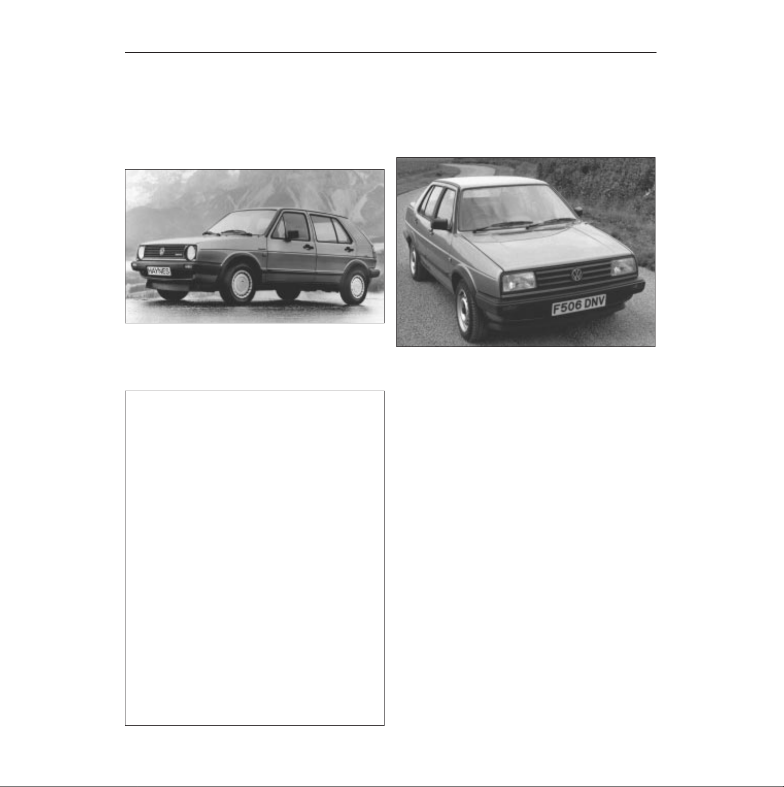
The Mk. II Volkswagen Golf and Jetta range of models was
introduced in March 1984, revised body and trim features being the
main visual difference to the earlier range of models.
The engine/transmission is mounted transversely at the front of the
vehicle, drive being to the front wheels. Detailed improvements have
been made throughout the years of manufacture to improve power
output and economy. These include the introduction of hydraulic
bucket tappets, the Digifant, Digijet and Mono-Jetronic fuel injection
systems, the 16-valve engine fitted to the GTi variant, the fully
electronic ignition system (FEI), the 085 5-speed gearbox and several
other minor modifications and revisions.
As with earlier models the new range is proving popular, giving
economy, reliability, comfort and, if previous models can be used as a
yardstick, long life.
0•4 Introduction
Your Volkswagen Golf and
Jetta Manual
The aim of this Manual is to help you get the best value from your
vehicle. It can do so in several ways. It can help you decide what work
must be done (even should you choose to get it done by a garage),
provide information on routine maintenance and servicing, and give a
logical course of action and diagnosis when random faults occur.
However, it is hoped that you will use the Manual by tackling the work
yourself. On simpler jobs it may even be quicker than booking the car
into a garage and going there twice, to leave and collect it. Perhaps
most important, a lot of money can be saved by avoiding the costs a
garage must charge to cover its labour and overheads.
The Manual has drawings and descriptions to show the function of
the various components so that their layout can be understood. Then
the tasks are described and photographed in a clear step-by-step
sequence.
Acknowledgements
Thanks are due to Champion Spark Plug who supplied the
illustrations showing spark plug conditions, to Duckhams Oils, who
provided lubrication data and also to Sykes-Pickavant Limited, who
supplied some of the workshop tools, and to all those people at
Sparkford who helped in the production of this Manual.
We take great pride in the accuracy of information given in this
Manual, but vehicle manufacturers make alterations and design
changes during the production run of a particular vehicle of which
they do not inform us. No liability can be accepted by the authors
or publishers for loss, damage or injury caused by any errors in, or
omissions from the information given.
The VW Golf & Jetta Team
Haynes manuals are produced by dedicated and
enthusiastic people working in close co-operation. The
team responsible for the creation of this book included:
Authors Ian Coomber
Cristopher Rogers
Sub-editors Carole Turk
Sophie Yar
Editor & Page Make-up Steve Churchill
Workshop manager Paul Buckland
Photo Scans John Martin
Paul Tanswell
Steve Tanswell
Cover illustration & Line Art Roger Healing
We hope the book will help you to get the maximum
enjoyment from your car. By carrying out routine
maintenance as described you will ensure your car’s
reliability and preserve its resale value.
VW Golf
VW Jetta
Page 5
Safety first! 0•5
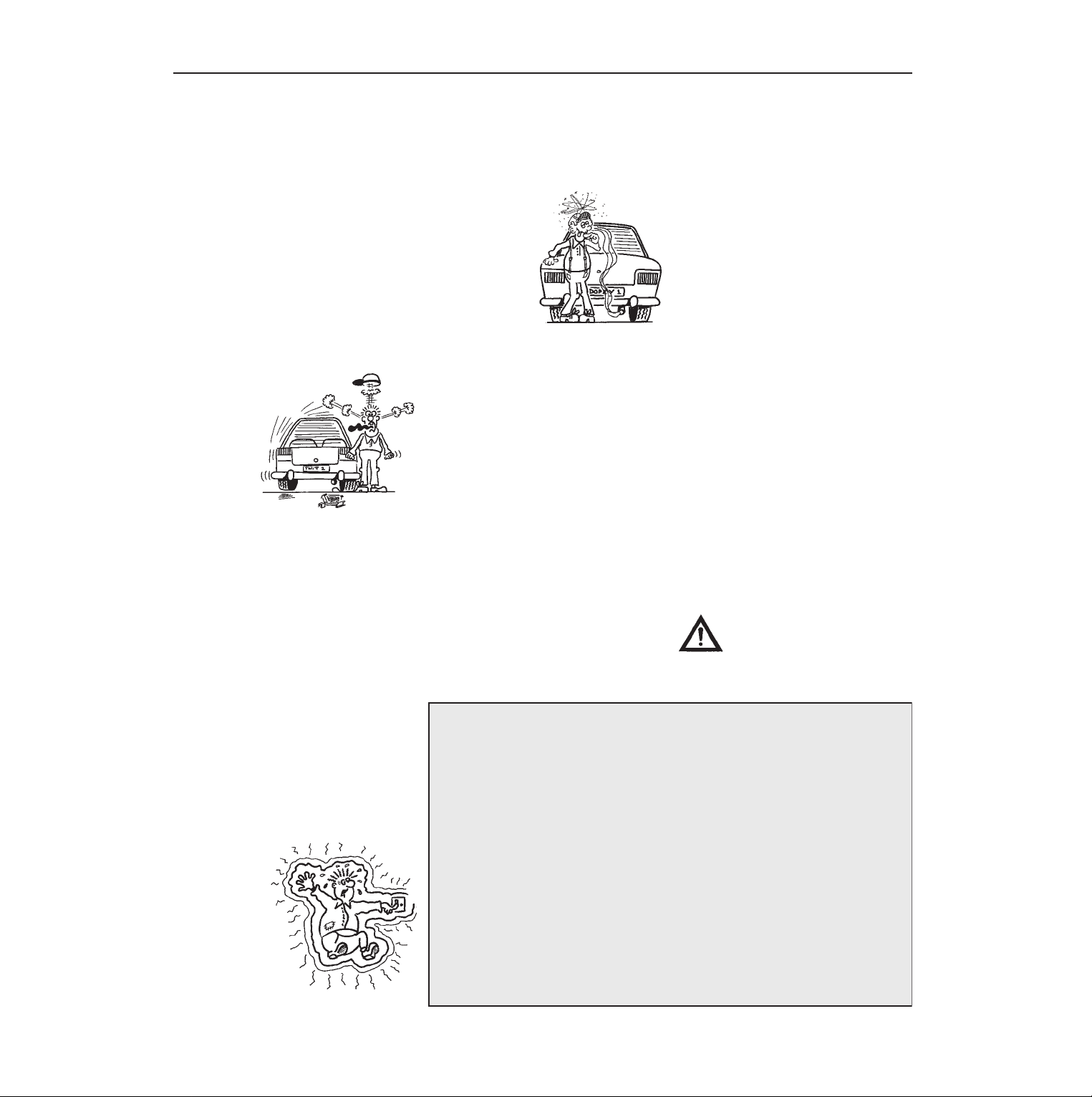
Working on your car can be dangerous.
This page shows just some of the potential
risks and hazards, with the aim of creating a
safety-conscious attitude.
General hazards
Scalding
• Don’t remove the radiator or expansion
tank cap while the engine is hot.
• Engine oil, automatic transmission fluid or
power steering fluid may also be dangerously
hot if the engine has recently been running.
Burning
• Beware of burns from the exhaust system
and from any part of the engine. Brake discs
and drums can also be extremely hot
immediately after use.
Crushing
• When working under or near
a raised vehicle,
always
supplement the
jack with axle
stands, or use
drive-on
ramps.
Never
venture
under a car which
is only supported by a jack.
• Take care if loosening or tightening hightorque nuts when the vehicle is on stands.
Initial loosening and final tightening should
be done with the wheels on the ground.
Fire
• Fuel is highly flammable; fuel vapour is
explosive.
• Don’t let fuel spill onto a hot engine.
• Do not smoke or allow naked lights
(including pilot lights) anywhere near a
vehicle being worked on. Also beware of
creating sparks
(electrically or by use of tools).
• Fuel vapour is heavier than air, so don’t
work on the fuel system with the vehicle over
an inspection pit.
• Another cause of fire is an electrical
overload or short-circuit. Take care when
repairing or modifying the vehicle wiring.
• Keep a fire extinguisher handy, of a type
suitable for use on fuel and electrical fires.
Electric shock
• Ignition HT
voltage can be
dangerous,
especially to
people with heart
problems or a
pacemaker. Don’t
work on or near the
ignition system with
the engine running or
the ignition switched on.
• Mains voltage is also dangerous. Make
sure that any mains-operated equipment is
correctly earthed. Mains power points should
be protected by a residual current device
(RCD) circuit breaker.
Fume or gas intoxication
• Exhaust fumes are
poisonous; they often
contain carbon
monoxide, which is
rapidly fatal if inhaled.
Never run the
engine in a
confined space
such as a garage
with the doors shut.
• Fuel vapour is also
poisonous, as are the vapours from some
cleaning solvents and paint thinners.
Poisonous or irritant substances
• Avoid skin contact with battery acid and
with any fuel, fluid or lubricant, especially
antifreeze, brake hydraulic fluid and Diesel
fuel. Don’t syphon them by mouth. If such a
substance is swallowed or gets into the eyes,
seek medical advice.
• Prolonged contact with used engine oil can
cause skin cancer. Wear gloves or use a
barrier cream if necessary. Change out of oilsoaked clothes and do not keep oily rags in
your pocket.
• Air conditioning refrigerant forms a
poisonous gas if exposed to a naked flame
(including a cigarette). It can also cause skin
burns on contact.
Asbestos
• Asbestos dust can cause cancer if inhaled
or swallowed. Asbestos may be found in
gaskets and in brake and clutch linings.
When dealing with such components it is
safest to assume that they contain asbestos.
Special hazards
Hydrofluoric acid
• This extremely corrosive acid is formed
when certain types of synthetic rubber, found
in some O-rings, oil seals, fuel hoses etc, are
exposed to temperatures above 400
0
C. The
rubber changes into a charred or sticky
substance containing the acid. Once formed,
the acid remains dangerous for years. If it
gets onto the skin, it may be necessary to
amputate the limb concerned.
• When dealing with a vehicle which has
suffered a fire, or with components salvaged
from such a vehicle, wear protective gloves
and discard them after use.
The battery
• Batteries contain sulphuric acid, which
attacks clothing, eyes and skin. Take care
when topping-up or carrying the battery.
• The hydrogen gas given off by the battery
is highly explosive. Never cause a spark or
allow a naked light nearby. Be careful when
connecting and disconnecting battery
chargers or jump leads.
Air bags
• Air bags can cause injury if they go off
accidentally. Take care when removing the
steering wheel and/or facia. Special storage
instructions may apply.
Diesel injection equipment
• Diesel injection pumps supply fuel at very
high pressure. Take care when working on
the fuel injectors and fuel pipes.
Warning: Never expose the hands,
face or any other part of the body
to injector spray; the fuel can
penetrate the skin with potentially fatal
results.
Remember...
DO
• Do use eye protection when using power
tools, and when working under the vehicle.
• Do wear gloves or use barrier cream to
protect your hands when necessary.
• Do get someone to check periodically
that all is well when working alone on the
vehicle.
• Do keep loose clothing and long hair well
out of the way of moving mechanical parts.
• Do remove rings, wristwatch etc, before
working on the vehicle – especially the
electrical system.
• Do ensure that any lifting or jacking
equipment has a safe working load rating
adequate for the job.
A few tips
DON’T
• Don’t attempt to lift a heavy component
which may be beyond your capability – get
assistance.
• Don’t rush to finish a job, or take
unverified short cuts.
• Don’t use ill-fitting tools which may slip
and cause injury.
• Don’t leave tools or parts lying around
where someone can trip over them. Mop
up oil and fuel spills at once.
• Don’t allow children or pets to play in or
near a vehicle being worked on.
Page 6
0•6 Roadside repairs
The following pages are intended to help in dealing with
common roadside emergencies and breakdowns. You will find
more detailed fault finding information at the back of the
manual, and repair information in the main chapters.
If your car won’t start
and the starter motor
doesn’t turn
M If it’s a model with automatic transmission, make sure the
selector is in ‘P’ or ‘N’.
M Open the bonnet and make sure that the battery terminals
are clean and tight.
M Switch on the headlights and try to start the engine. If the
headlights go very dim when you’re trying to start, the
battery is probably flat. Get out of trouble by jump starting
(see next page) using a friend’s car.
If your car won’t start
even though the starter
motor turns as normal
M Is there fuel in the tank?
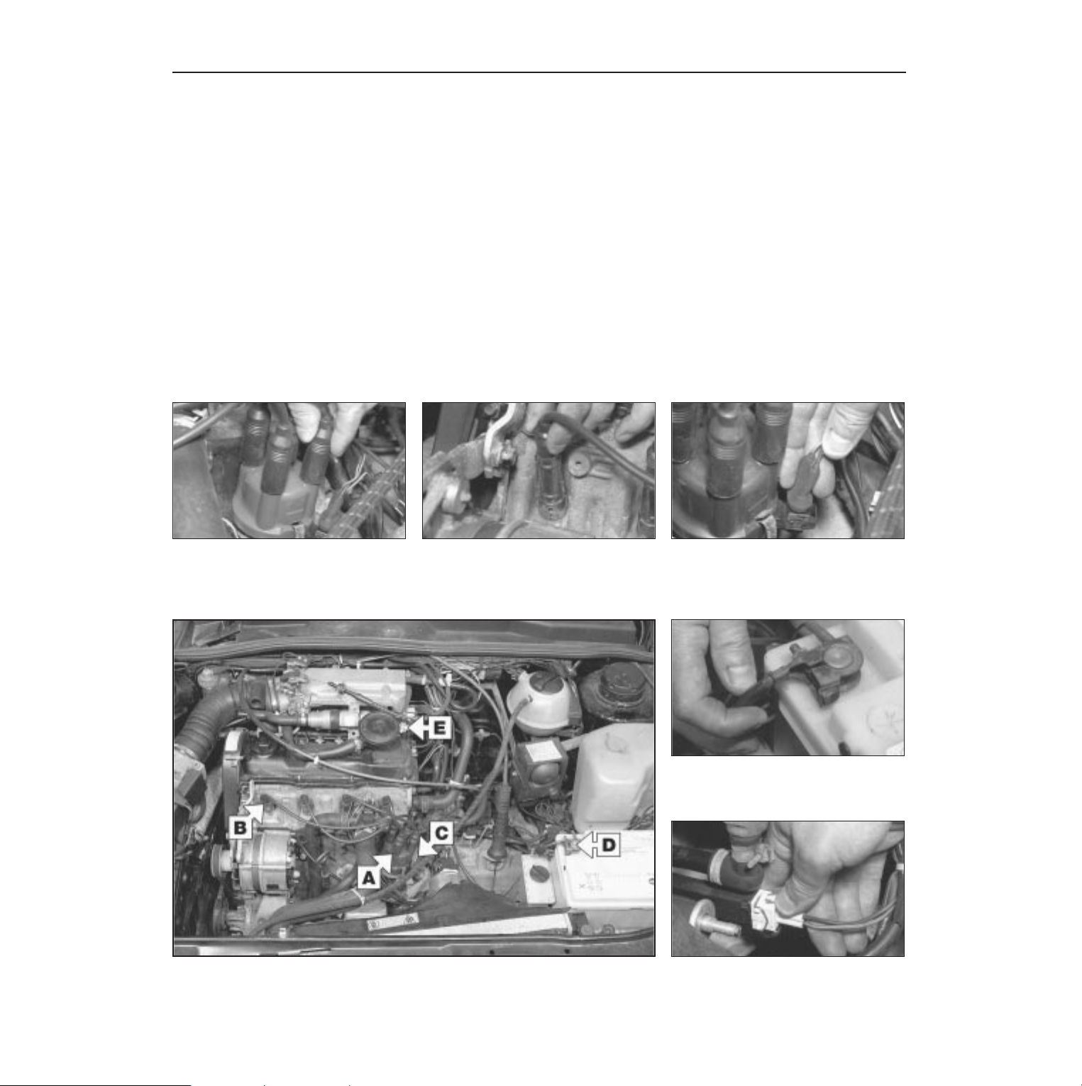
M Is there moisture on electrical components under the
bonnet? Switch off the ignition, then wipe off any obvious
dampness with a dry cloth. Spray a water-repellent aerosol
product (WD-40 or equivalent) on ignition and fuel system
electrical connectors like those shown in the photos.
Pay special attention to the ignition coil wiring connector
and HT leads.
Check that the HT lead connections at
the distributor are clean and make sure
they are secure by pushing them onto
the cap.
A
Check that the HT lead connections at
the spark plugs are secure by pushing
them onto the plugs.
B
Check that the LT lead connections are
clean and secure.
C
Check the security and condition of the
battery connections.
D
Wiring plugs may cause problems if dirty
or not connected properly.
E
Check that electrical connections are secure (with the ignition switched off) and spray them
with a water dispersant spray like WD40 if you suspect a problem due to damp
Page 7
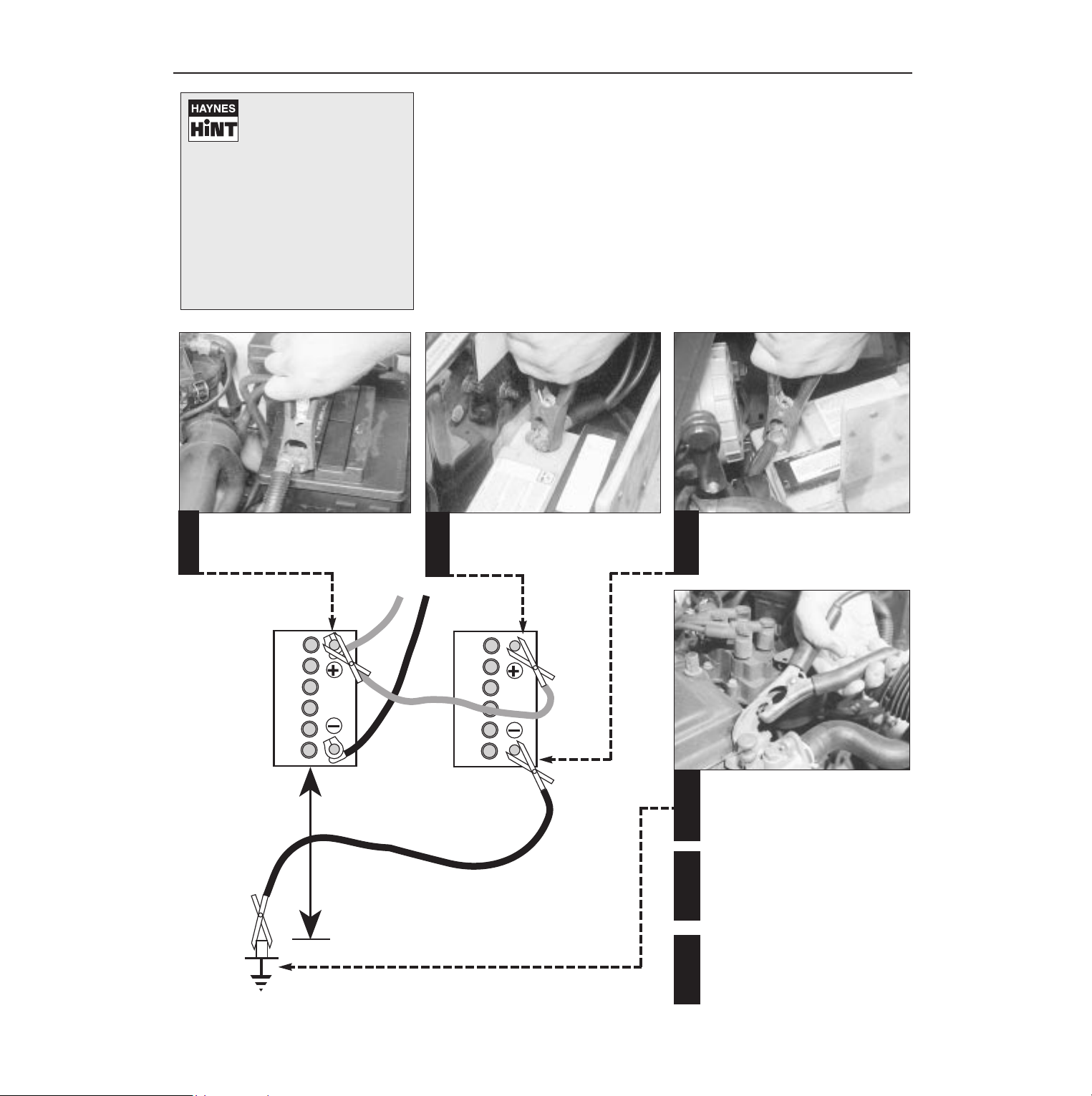
Roadside repairs 0•7
When jump-starting a car using a
booster battery, observe the following
precautions:
4 Before connecting the booster
battery, make sure that the ignition is
switched off.
4 Ensure that all electrical equipment
(lights, heater, wipers, etc) is
switched off.
4 Make sure that the booster battery is
the same voltage as the discharged
one in the vehicle.
4 If the battery is being jump-started
from the battery in another vehicle,
the two vehcles MUST NOT TOUCH
each other.
4 Make sure that the transmission is in
neutral (or PARK, in the case of
automatic transmission).
Jump starting will get you out
of trouble, but you must correct
whatever made the battery go
flat in the first place. There are
three possibilities:
1
The battery has been drained by
repeated attempts to start, or by
leaving the lights on.
2
The charging system is not working
properly (alternator drivebelt slack
or broken, alternator wiring fault or
alternator itself faulty).
3
The battery itself is at fault
(electrolyte low, or battery worn out).
Connect one end of the red jump lead to
the positive (+) terminal of the flat
battery
Connect the other end of the red lead to
the positive (+) terminal of the booster
battery.
Connect one end of the black jump lead
to the negative (-) terminal of the
booster battery
Connect the other end of the black
jump lead to a bolt or bracket on the
engine block, well away from the
battery, on the vehicle to be started.
1
2
3
4
Make sure that the jump leads will not
come into contact with the fan, drivebelts or other moving parts of the
engine.
5
Start the engine using the booster
battery, then with the engine running at
idle speed, disconnect the jump leads in
the reverse order of connection.
6
Jump starting
Page 8
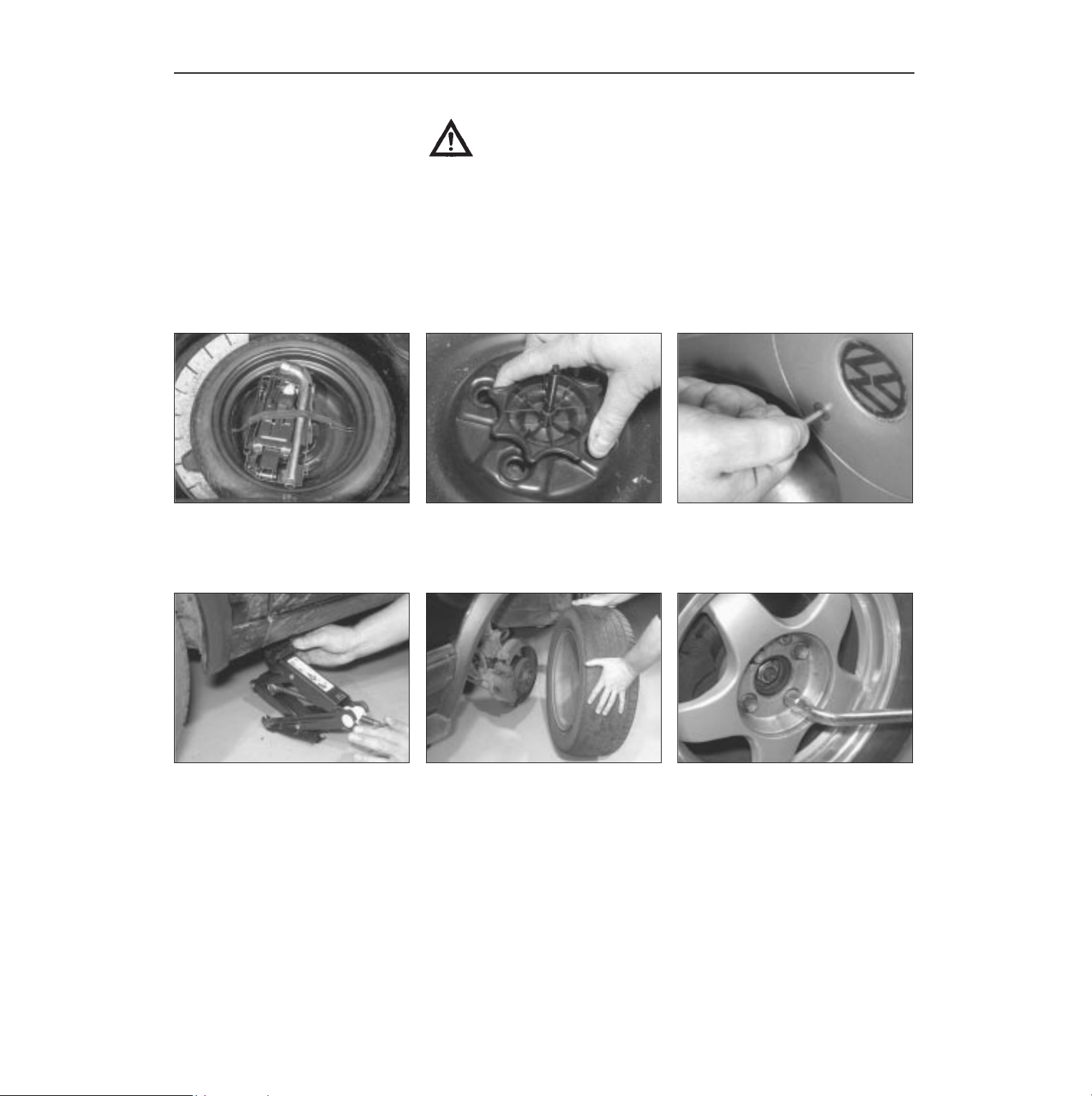
0•8 Roadside repairs
The spare wheels and tools are stored in
the luggage compartment. Release the
retaining strap and lift out the jack and
tools from the centre of the wheel.
Finally...
M Remove the wheel chocks.
M Stow the jack and tools in the correct locations in the car.
M
Check the tyre pressure on the wheel just fitted. If it is low, or if you don’t have a pressure
gauge with you, drive slowly to the nearest garage and inflate the tyre to the right pressure.
M Have the damaged tyre or wheel repaired as soon as possible.
Locate the jack below the reinforced
point on the sill and on firm ground. Turn
the jack handle to raise the car until the
wheel is clear of the ground.
Unscrew the wheel bolts and remove the
wheel. Fit the spare wheel and screw in
the wheel bolts. Lightly tighten them
using the wheelbrace, then lower the car to
the ground.
Once the car is on the ground, tighten the
wheel bolts securely in a diagonal pattern
using the wheelbrace. At the earliest
possible opportunity, have the wheel bolts
slackened and then tightened to the correct
torque wrench setting.
Remove the wheel trim/hub cap from the
wheel (some trims have retaining screws
which must be undone first). Slacken
each wheel bolt by half a turn.
Unscrew the retaining nut and lift the
wheel out of the vehicle.
1 2 3
4 5 6
Preparation
M When a puncture occurs, stop as soon as
it is safe to do so.
M Park on firm level ground, if possible,
and well out of the way of other traffic.
M Use hazard warning lights if necessary.
M If you have one, use a warning triangle to
alert other drivers of your presence.
M Apply the handbrake and engage first or
reverse gear (or Park on models with
automatic transmission.
M Chock the wheel diagonally opposite the
one being removed – a couple of large
stones will do for this.
M If the ground is soft, use a flat piece of
wood to spread the load under the jack.
Changing the wheel
Wheel changing
Some of the details shown here will vary
according to model. For instance, the location
of the spare wheel and jack is not the same on
all cars. However, the basic principles apply
to all vehicles.
Warning: Do not change a wheel in a situation where you risk being hit by
another vehicle. On busy roads, try to stop in a lay-by or a gateway. Be wary of
passing traffic while changing the wheel - it is easy to become distracted by
the job in hand.
Page 9
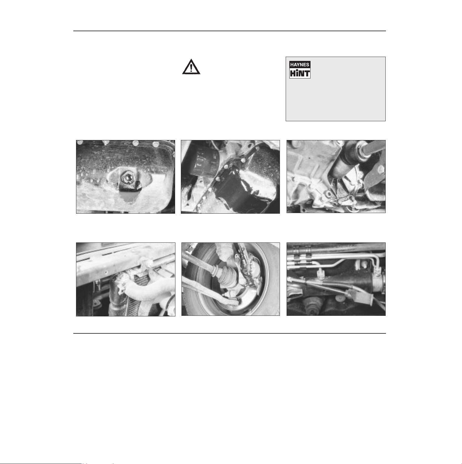
Roadside repairs 0•9
When all else fails, you may find yourself
having to get a tow home – or of course you
may be helping somebody else. Long-distance
recovery should only be done by a garage or
breakdown service. For shorter distances, DIY
towing using another car is easy enough, but
observe the following points:
M Use a proper tow-rope – they are not
expensive. The vehicle being towed must
display an ‘ON TOW’ sign in its rear window.
M Always turn the ignition key to the ‘on’
position when the vehicle is being towed, so
that the steering lock is released, and that the
direction indicator and brake lights will work.
M Only attach the tow-rope to the towing
eyes provided.
M Before being towed, release the handbrake
and select neutral on the transmission.
M Note that greater-than-usual pedal
pressure will be required to operate the
brakes, since the vacuum servo unit is only
operational with the engine running.
M On models with power steering, greaterthan-usual steering effort will also be required.
M The driver of the car being towed must
keep the tow-rope taut at all times to avoid
snatching.
M Make sure that both drivers know the route
before setting off.
M Only drive at moderate speeds and keep
the distance towed to a minimum. Drive
smoothly and allow plenty of time for slowing
down at junctions.
M On models with automatic transmission,
special precautions apply. If in doubt, do not
tow, or transmission damage may result.
Towing
Puddles on the garage floor or drive, or
obvious wetness under the bonnet or
underneath the car, suggest a leak that needs
investigating. It can sometimes be difficult to
decide where the leak is coming from,
especially if the engine bay is very dirty
already. Leaking oil or fluid can also be blown
rearwards by the passage of air under the car,
giving a false impression of where the
problem lies.
Warning: Most automotive oils
and fluids are poisonous. Wash
them off skin, and change out of
contaminated clothing, without
delay.
Identifying leaks
The smell of a fluid leaking
from the car may provide a
clue to what’s leaking. Some
fluids are distinctively
coloured. It may help to clean the car
carefully and to park it over some clean
paper overnight as an aid to locating the
source of the leak.
Remember that some leaks may only
occur while the engine is running.
Sump oil Gearbox oil
Brake fluid Power steering fluid
Oil from filter
Antifreeze
Engine oil may leak from the drain plug... ...or from the base of the oil filter.
Leaking antifreeze often leaves a crystalline
deposit like this.
Gearbox oil can leak from the seals at the
inboard ends of the driveshafts.
A leak occurring at a wheel is almost
certainly brake fluid.
Power steering fluid may leak from the pipe
connectors on the steering rack.
Page 10
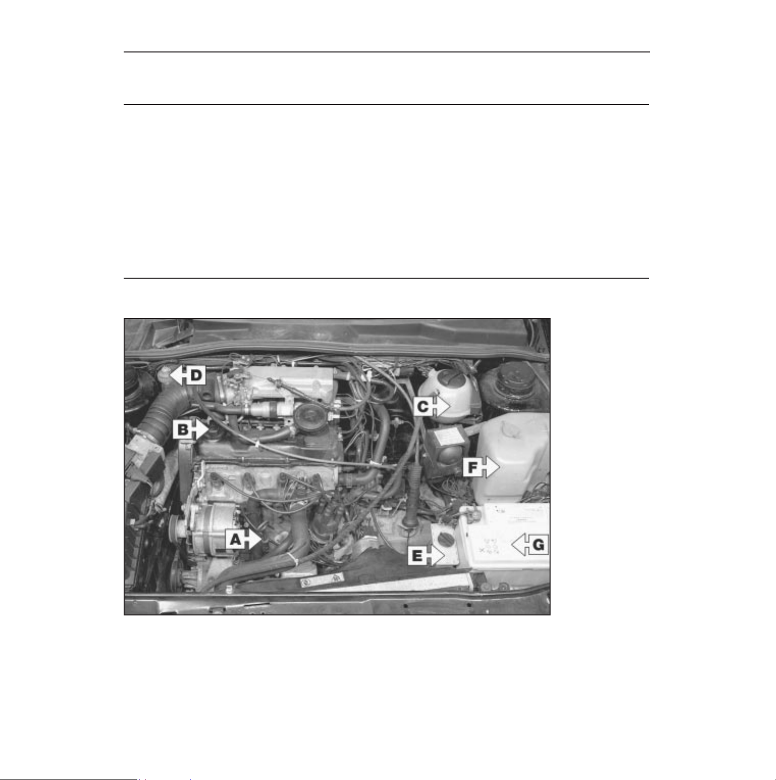
0•10 Weekly checks
There are some very simple checks which
need only take a few minutes to carry out, but
which could save you a lot of inconvenience
and expense.
These "Weekly checks" require no great skill
or special tools, and the small amount of time
they take to perform could prove to be very
well spent, for example;
M Keeping an eye on tyre condition and
pressures, will not only help to stop them
wearing out prematurely, but could also save
your life.
M
Many breakdowns are caused by electrical
problems. Battery-related faults are particularly
common, and a quick check on a regular basis
will often prevent the majority of
these.
M If your car develops a brake fluid leak, the
first time you might know about it is when
your brakes don't work properly. Checking
the level regularly will give advance warning of
this kind of problem.
M If the oil or coolant levels run low, the cost
of repairing any engine damage will be far
greater than fixing the leak, for example.
Introduction
§
All models
(typical)
A
Engine oil level
dipstick
B
Engine oil filler cap
C
Coolant expansion
tank
D
Brake fluid reservoir
E
Power steering fluid
reservoir
F
Screen washer fluid
reservoir
G
Battery
Underbonnet check points
Page 11
Weekly checks 0•11
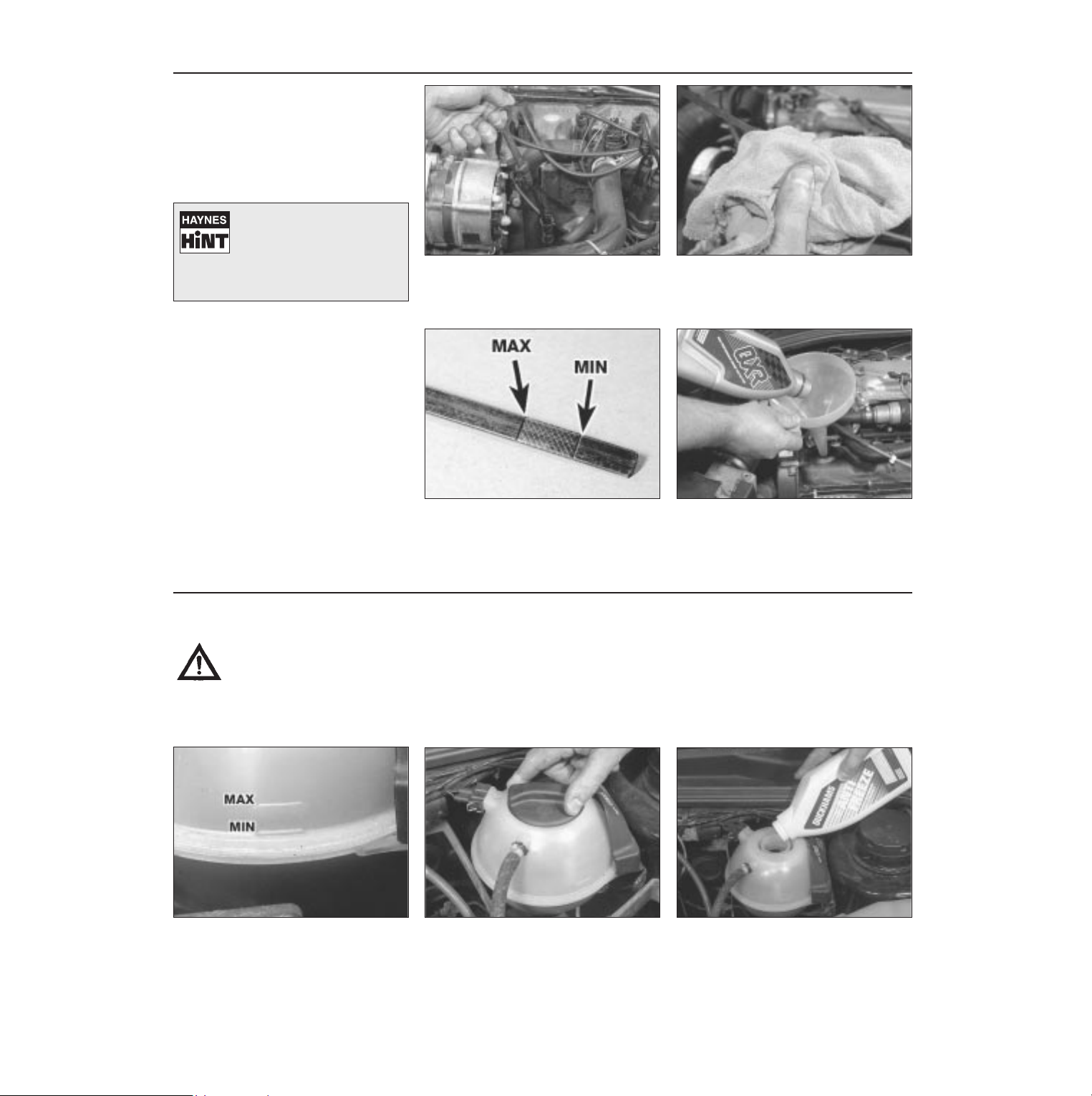
Engine oil level
Before you start
4 Make sure that your car is on level ground.
4 Check the oil level before the car is driven,
or at least 5 minutes after the engine has been
switched off.
The correct oil
Modern engines place great demands on their
oil. It is very important that the correct oil for
your car is used (See “Lubricants, fluids and
capacities”).
Car Care
l If you have to add oil frequently, you should
check whether you have any oil leaks. Place
some clean paper under the car overnight,
and check for stains in the morning. If there
are no leaks, the engine may be burning oil
(see “Fault Finding”).
l Always maintain the level between the
upper and lower dipstick marks (see photo 3).
If the level is too low severe engine damage
may occur. Oil seal failure may result if the
engine is overfilled by adding too much oil.
If the oil is checked immediately after driving the
vehicle, some of the oil will
remain in the upper engine
components, resulting in an inaccurate
reading on the dipstick!
The dipstick is located at the right-hand
end of the engine (see “Underbonnet
check points” on page 0•10 for exact
location). Withdraw the dipstick.
Using a clean rag or paper towel remove
all oil from the dipstick. Insert the clean
dipstick into the tube as far as it will go,
then withdraw it again.
Note the oil level on the end of the
dipstick, which should be between the
upper ("MAX") mark and lower ("MIN")
mark. Approximately 1.0 litre of oil will raise
the level from the lower mark to the upper
mark.
Oil is added through the filler cap.
Unscrew the cap and top-up the level; a
funnel may help to reduce spillage. Add
the oil slowly, checking the level on the dipstick
often. Don’t overfill (see “Car Care” left).
1 2
3 4
Warning: DO NOT attempt to
remove the expansion tank
pressure cap when the engine
is hot, as there is a very great
risk of scalding. Do not leave
open containers of coolant
about, as it is poisonous.
Car Care
l With a sealed-type cooling system, adding
coolant should not be necessary on a regular
basis. If frequent topping-up is required, it is
likely there is a leak. Check the radiator, all
hoses and joint faces for signs of staining or
wetness, and rectify as necessary.
l It is important that antifreeze is used in the
cooling system all year round, not just during
the winter months. Don’t top-up with water
alone, as the antifreeze will become too
diluted.
Coolant level
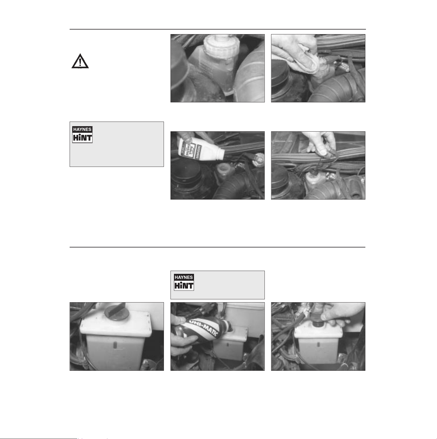
The coolant level varies with the
temperature of the engine. When the
engine is cold, the coolant level should
be between the MAX and MIN marks on the
side of the expansion tank. When the engine
is hot, the level may rise slightly.
If topping up is necessary, wait until the
engine is cold. Slowly unscrew the
expansion tank cap, to release any
pressure present in the cooling system, and
remove it.
Add the recommended mixture of water
and antifreeze through the expansion
tank filler neck, until the coolant is up to
the MAX level mark. Refit the cap, turning it
clockwise as far as it will go until it is secure.
1
2 3
Page 12
0•12 Weekly checks
Brake fluid level
Warning:
l Brake fluid can harm your
eyes and damage painted
surfaces, so use extreme
caution when handling and
pouring it.
l Do not use fluid that has
been standing open for some
time, as it absorbs moisture
from the air, which can cause a
dangerous loss of braking
effectiveness.
Safety First!
l If the reservoir requires repeated toppingup this is an indication of a fluid leak
somewhere in the system, which should be
investigated immediately.
l If a leak is suspected, the car should not be
driven until the braking system has been
checked. Never take any risks where brakes
are concerned.
• Make sure that your car is
on level ground.
• The fluid level in the
reservoir will drop slightly as
the brake pads wear down, but the fluid
level must never be allowed to drop
below the “MIN” mark.
The “MAX” and “MIN” marks are
indicated on the front of the reservoir.
The fluid level must be kept between the
marks at all times.
1
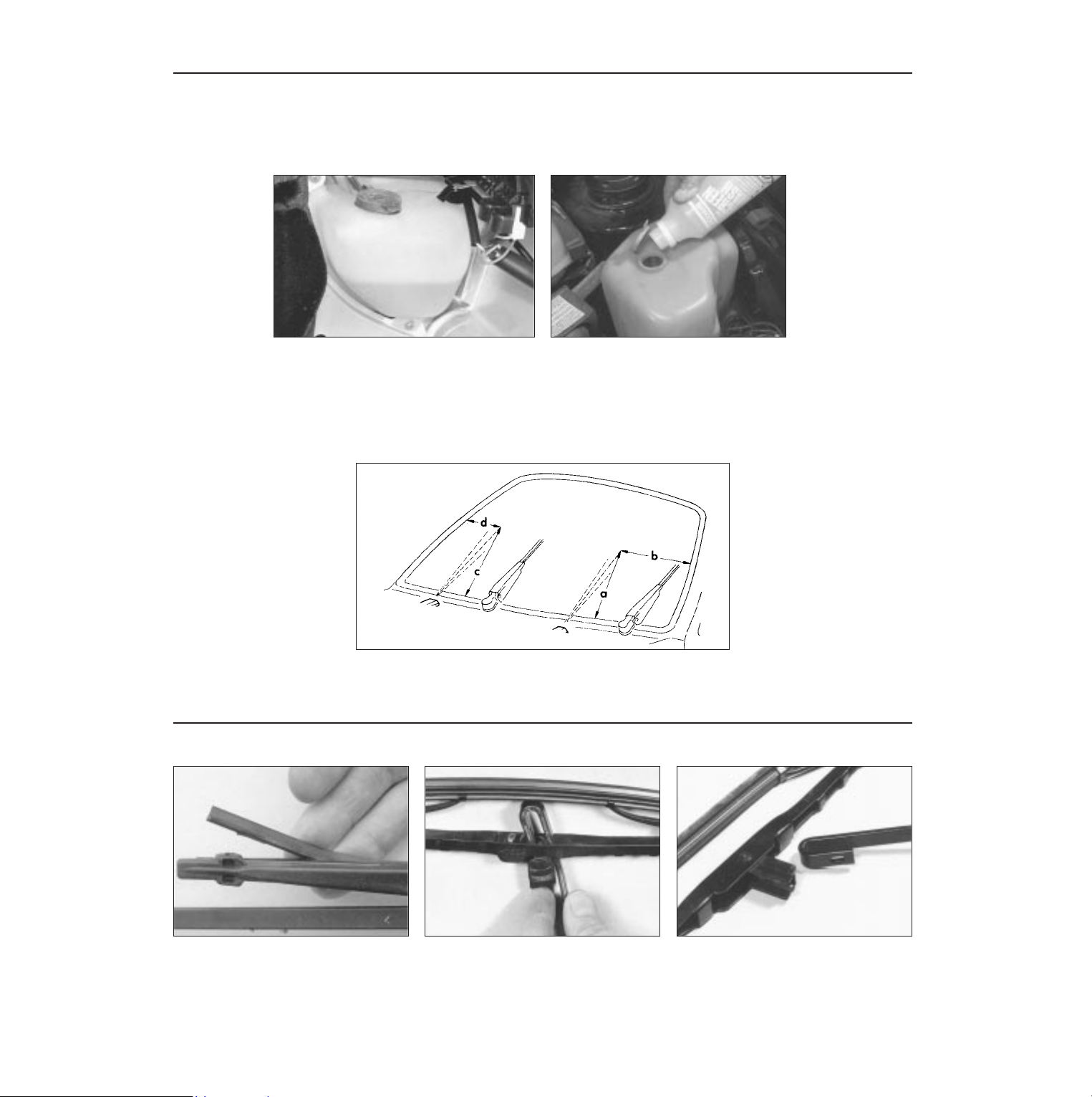
If topping-up is necessary, first wipe
clean the area around the filler cap to
prevent dirt entering the hydraulic
system.
2
Unscrew the reservoir cap and carefully
lift it out of position, taking care not to
damage the level switch float. Inspect the
reservoir, if the fluid is dirty the hydraulic
system should be drained and refilled (see
Chapter 1).
3
Carefully add fluid, taking care not to spill
it onto the surrounding components. Use
only the specified fluid; mixing different
types can cause damage to the system. After
topping-up to the correct level, securely refit
the cap and wipe off any spilt fluid.
4
Power steering fluid level
Before you start:
4 Park the vehicle on level ground.
4 Set the steering wheel straight-ahead.
4 The engine should be turned off.
Safety First!
l The need for frequent topping-up indicates
a leak, which should be investigated
immediately.
For the check to be
accurate, the steering must
not be turned once the
engine has been stopped.
The fluid reservoir is mounted next to the
battery in the engine compartment.
“MAX” and “MIN” level marks are
indicated on the side of the reservoir. The fluid
level should be maintained between these
marks at all times.
1
If topping-up is necessary, first wipe the
area around the filler cap with a clean rag
before removing the cap. When adding
fluid, pour it carefully into the reservoir to
avoid spillage. Be sure to use only the
specified fluid.
2
After filling the reservoir to the proper
level, make sure that the cap is refitted
securely to avoid leaks and the entry of
foreign matter into the reservoir.
3
Page 13
Weekly checks 0•13
Screenwash additives not only keep the
winscreen clean during foul weather, they also
prevent the washer system freezing in cold
weather - which is when you are likely to need it
most. Don’t top up using plain water as the
screenwash will become too diluted, and will
freeze during cold weather. On no account use
coolant antifreeze in the washer system this could discolour or damage paintwork.
Screen/headlamp washer fluid level
When topping-up the reservoir(s) a
screenwash additive should be added in
the quantities recommended on the
bottle.
2
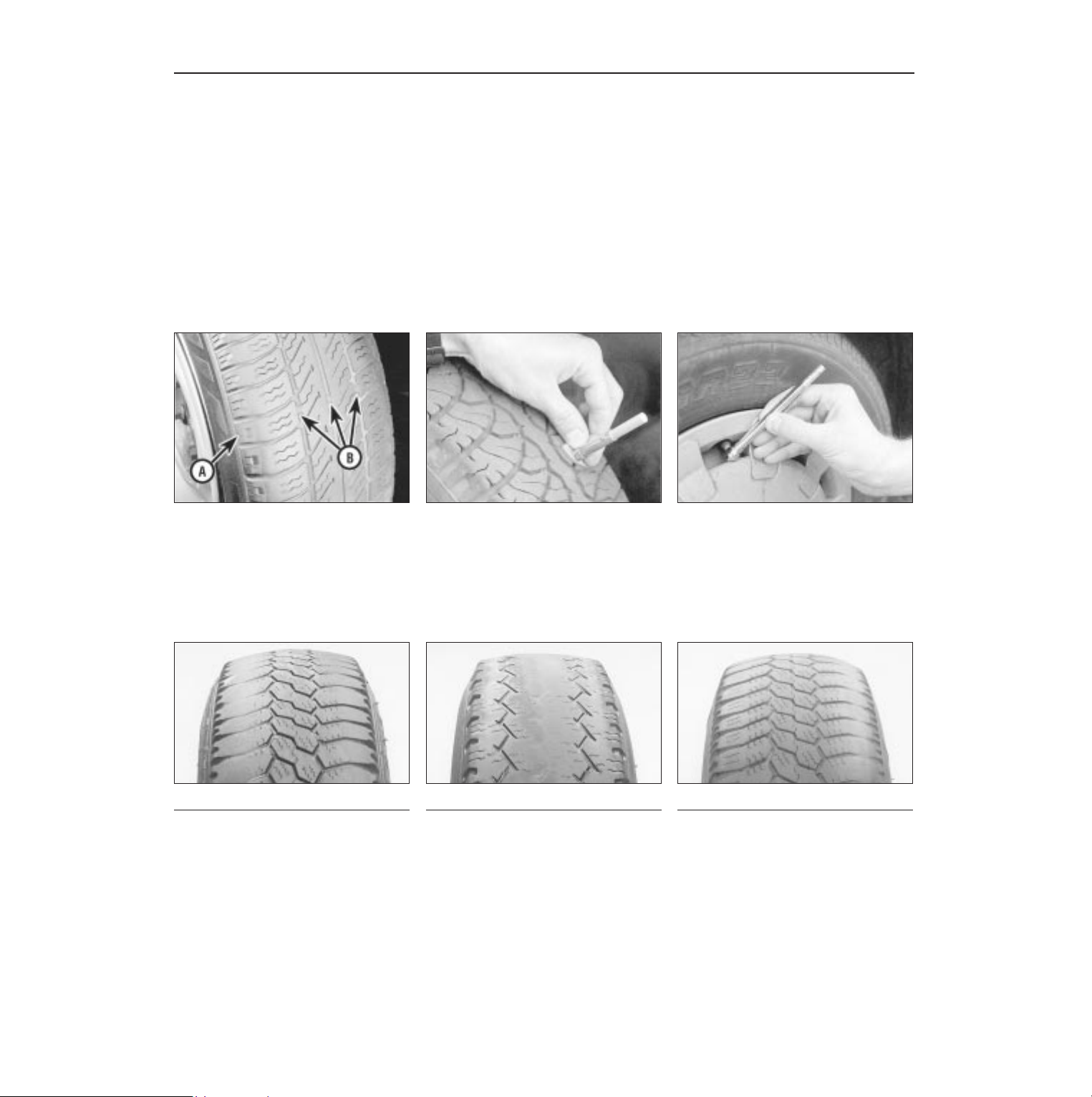
The reservoir for the windscreen and
headlamp washer systems is located on the
left-hand side of the engine compartment,
forward of the suspension turret. The rear screen
washer system reservoir is located on the
right-hand side rear corner of the luggage
compartment. Later systems have a single
reservoir located in the engine compartment.
1
Check the operation of both screen and headlamp washers. Adjust
the nozzles using a pin if necessary, aiming the spray to a point
slightly above the centre of the swept area.
a = 345 mm b = 420 mm c = 320 mm d = 300 mm
3
Wiper blades
Check the condition of the wiper blades;
if they are cracked or show any signs of
deterioration, or if the glass swept area is
smeared, renew them. Wiper blades should
be renewed annually.
1
To remove a windscreen wiper blade, pull
the arm fully away from the screen until it
locks. Swivel the blade through 90°,
press the locking tab with your fingers and
slide the blade out of the arm’s hooked end.
2
Don’t forget to check the tailgate wiper
blade as well. To remove the blade,
depress the retaining tab and slide the
blade out of the hooked end of the arm.
3
Page 14
0•14 Weekly checks
Tyre condition and pressure
It is very important that tyres are in good
condition, and at the correct pressure - having
a tyre failure at any speed is highly dangerous.
Tyre wear is influenced by driving style - harsh
braking and acceleration, or fast cornering,
will all produce more rapid tyre wear. As a
general rule, the front tyres wear out faster
than the rears. Interchanging the tyres from
front to rear ("rotating" the tyres) may result in
more even wear. However, if this is
completely effective, you may have the
expense of replacing all four tyres at once!
Remove any nails or stones embedded in the
tread before they penetrate the tyre to cause
deflation. If removal of a nail does reveal that
the tyre has been punctured, refit the nail so
that its point of penetration is marked. Then
immediately change the wheel, and have the
tyre repaired by a tyre dealer.
Regularly check the tyres for damage in the
form of cuts or bulges, especially in the
sidewalls. Periodically remove the wheels,
and clean any dirt or mud from the inside and
outside surfaces. Examine the wheel rims for
signs of rusting, corrosion or other damage.
Light alloy wheels are easily damaged by
"kerbing" whilst parking; steel wheels may
also become dented or buckled. A new wheel
is very often the only way to overcome severe
damage.
New tyres should be balanced when they are
fitted, but it may become necessary to rebalance them as they wear, or if the balance
weights fitted to the wheel rim should fall off.
Unbalanced tyres will wear more quickly, as
will the steering and suspension components.
Wheel imbalance is normally signified by
vibration, particularly at a certain speed
(typically around 50 mph). If this vibration is
felt only through the steering, then it is likely
that just the front wheels need balancing. If,
however, the vibration is felt through the
whole car, the rear wheels could be out of
balance. Wheel balancing should be carried
out by a tyre dealer or garage.
Tread Depth - visual check
The original tyres have tread wear safety
bands (B), which will appear when the tread
depth reaches approximately 1.6 mm. The
band positions are indicated by a triangular
mark on the tyre sidewall (A).
1
Tread Depth - manual check
Alternatively, tread wear can be
monitored with a simple, inexpensive device
known as a tread depth indicator gauge.
2
Tyre Pressure Check
Check the tyre pressures regularly with
the tyres cold. Do not adjust the tyre
pressures immediately after the vehicle has
been used, or an inaccurate setting will result.
3
Tyre tread wear patterns
Shoulder Wear
Underinflation (wear on both sides)
Under-inflation will cause overheating of the
tyre, because the tyre will flex too much, and
the tread will not sit correctly on the road
surface. This will cause a loss of grip and
excessive wear, not to mention the danger of
sudden tyre failure due to heat build-up.
Check and adjust pressures
Incorrect wheel camber (wear on one side)
Repair or renew suspension parts
Hard cornering
Reduce speed!
Centre Wear
Overinflation
Over-inflation will cause rapid wear of the
centre part of the tyre tread, coupled with
reduced grip, harsher ride, and the danger of
shock damage occurring in the tyre casing.
Check and adjust pressures
If you sometimes have to inflate your car’s
tyres to the higher pressures specified for
maximum load or sustained high speed, don’t
forget to reduce the pressures to normal
afterwards.
Uneven Wear
Front tyres may wear unevenly as a result of
wheel misalignment. Most tyre dealers and
garages can check and adjust the wheel
alignment (or "tracking") for a modest charge.
Incorrect camber or castor
Repair or renew suspension parts
Malfunctioning suspension
Repair or renew suspension parts
Unbalanced wheel
Balance tyres
Incorrect toe setting
Adjust front wheel alignment
Note: The feathered edge of the tread which
typifies toe wear is best checked by feel.
Page 15
Weekly checks 0•15
Battery
Caution: Before carrying out any work on the
vehicle battery, read the precautions given in
"Safety first" at the start of this manual.
4 Make sure that the battery tray is in good
condition, and that the clamp is tight.
Corrosion on the tray, retaining clamp and the
battery itself can be removed with a solution
of water and baking soda. Thoroughly rinse all
cleaned areas with water. Any metal parts
damaged by corrosion should be covered
with a zinc-based primer, then painted.
4 Periodically (approximately every three
months), check the charge condition of the
battery as described in Chapter 5A.
4 If the battery is flat, and you need to jump
start your vehicle, see Roadside Repairs.
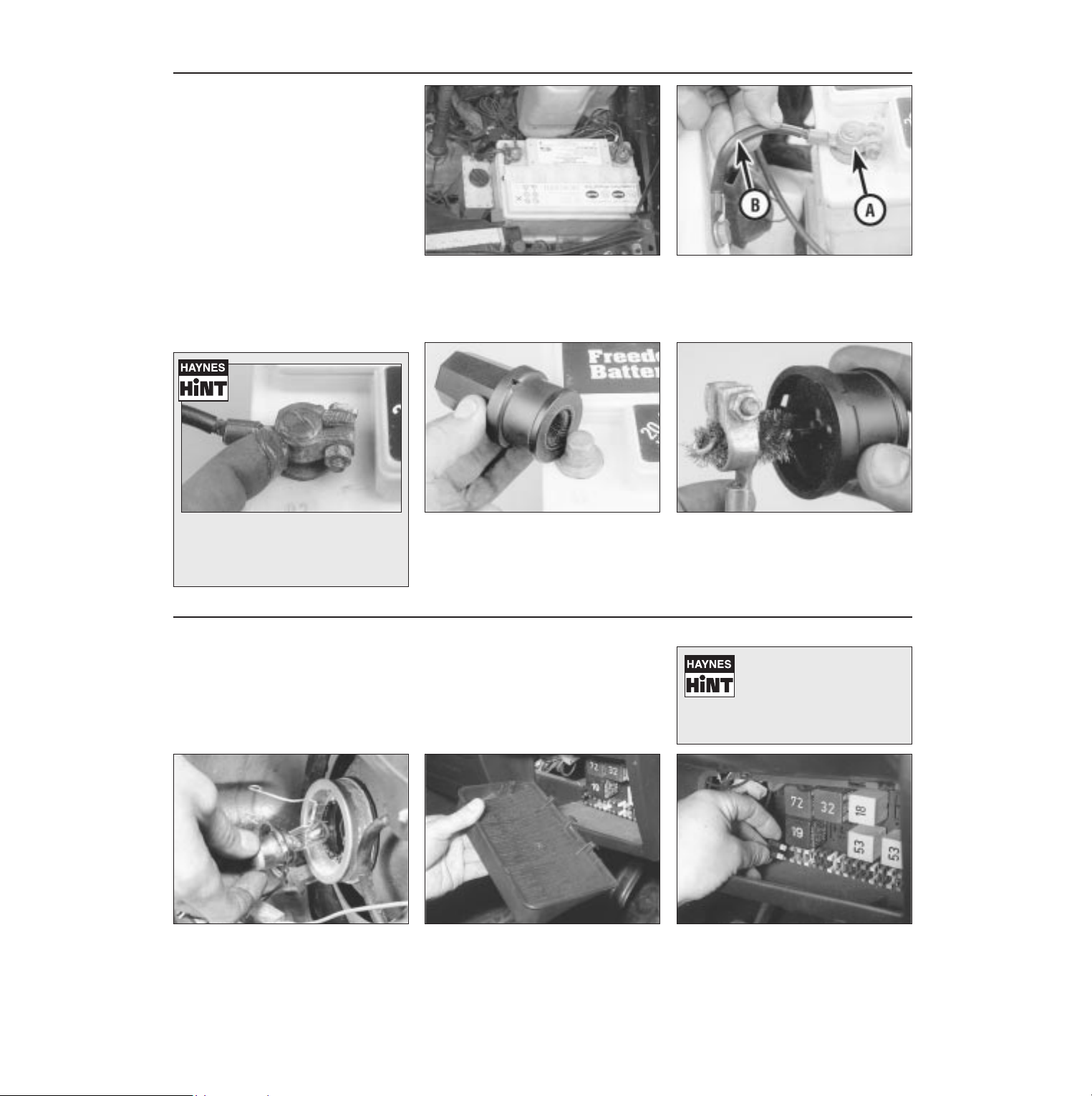
The battery is located on the left-hand
side of the engine compartment. The
exterior of the battery should be
inspected periodically for damage such as a
cracked case or cover.
1
Check the tightness of battery clamps (A)
to ensure good electrical connections.
You should not be able to move them.
Also check each cable (B) for cracks and
frayed conductors.
2
Battery corrosion can be kept to a
minimum by applying a layer of
petroleum jelly to the clamps and
terminals after they are reconnected.
If corrosion (white, fluffy deposits) is
evident, remove the cables from the
battery terminals, clean them with a small
wire brush, then refit them. Automotive stores
sell a tool for cleaning the battery post . . .
3
. . . as well as the battery cable clamps
4
Electrical systems
4 Check all external lights and the horn.
Refer to the appropriate Sections of Chapter 12 for details if any of the circuits are
found to be inoperative.
4 Visually check all accessible wiring
connectors, harnesses and retaining clips for
security, and for signs of chafing or damage.
If you need to check your
brake lights and indicators
unaided, back up to a wall or
garage door and operate the
lights. The reflected light should show if
they are working properly.
If a single indicator light, stop-light or
headlight has failed, it is likely that a bulb
has blown and will need to be replaced.
Refer to Chapter 12 for details. If both stoplights have failed, it is possible that the switch
has failed.
If more than one indicator light or tail light
has failed it is likely that either a fuse has
blown or that there is a fault in the circuit
(see Chapter 12). The fuses are located under
the facia panel, on the right-hand side, behind
a removable cover.
2
To replace a blown fuse, simply pull it out
and fit a new fuse of the correct rating
(see Chapter 12). If the fuse blows again,
it is important that you find out why - a
complete checking procedure is given in
Chapter 12.
3
1
Page 16
0•16 Lubricants and fluids
Lubricants and fluids
Component or system Lubricant or fluid
Engine . . . . . . . . . . . . . . . . . . . . . . . . . . . . . . Multigrade engine oil to viscosity SAE 15W/50 or 20W/50
Duckhams QXR, QS, Hypergrade Plus or Hypergrade
Cooling system . . . . . . . . . . . . . . . . . . . . . . Ethylene-glycol based antifreeze with corrosion inhibitors.
Duckhams Antifreeze & Summer Coolant. Mixture 50% by volume
Manual gearbox . . . . . . . . . . . . . . . . . . . . . Gear oil, viscosity SAE 80
Duckhams Hypoid 80 or Hypoid 75W/90S
Automatic transmission . . . . . . . . . . . . . . Dexron type ATF
Duckhams Uni-Matic
Final drive:
Manual gearbox . . . . . . . . . . . . . . . . . . . . . . Gear oil, viscosity SAE 80
Duckhams Hypoid 80 or Hypoid 75W/90S
Automatic transmission . . . . . . . . . . . . . . . . Gear oil, viscosity SAE 90EP
Duckhams Hypoid 90S or Hypoid 75W/90S
Brake hydraulic system . . . . . . . . . . . . . . Hydraulic fluid to FMVSS 11 6 DOT 4
Duckhams Universal Brake and Clutch Fluid
Power steering system:
pre-April 1989 . . . . . . . . . . . . . . . . . . . . . . . Dexron type ATF
Duckhams Uni-Matic
post-April 1989 . . . . . . . . . . . . . . . . . . . . . . VW oil G 002 000
No Duckhams equivalent
Oils perform vital tasks in all engines. The
higher the engine’s performance, the greater
the demand on lubricants to minimise wear as
well as optimise power and economy.
Duckhams tailors lubricants to the highest
technical standards, meeting and exceeding
the demands of all modern engines.
HOW ENGINE OIL WORKS
• Beating friction
Without oil, the surfaces inside your engine
which rub together will heat, fuse and quickly
cause engine seizure. Oil, and its special
additives, forms a molecular barrier between
moving parts, to stop wear and minimise heat
build-up.
• Cooling hot spots
Oil cools parts that the engine’s water-based
coolant cannot reach, bathing the combustion
chamber and pistons, where temperatures
may exceed 1000°C. The oil assists in
transferring the heat to the engine cooling
system. Heat in the oil is also lost by air flow
over the sump, and via any auxiliary oil cooler.
• Cleaning the inner engine
Oil washes away combustion by-products
(mainly carbon) on pistons and cylinders,
transporting them to the oil filter, and holding
the smallest particles in suspension until they
are flushed out by an oil change. Duckhams
oils undergo extensive tests in the laboratory,
and on the road.
Engine oil types
Mineral oils are the “traditional” oils,
generally suited to older engines and cars not
used in harsh conditions. Duckhams
Hypergrade Plus and Hypergrade are well
suited for use in most popular family cars.
Diesel oils such as Duckhams Diesel are
specially formulated for Diesel engines,
including turbocharged models and 4x4s.
Synthetic oils are the state-of-the-art in
lubricants, offering ultimate protection, but at
a fairly high price. One such is Duckhams QS,
for use in ultra-high performance engines.
Semi-synthetic oils offer high performance
engine protection, but at less cost than full
synthetic oils. Duckhams QXR is an ideal choice
for hot hatches and hard-driven cars.
For help with technical
queries on lubricants,
call Duckhams Oils
on 0181 290 8207
Choosing your engine oil
Note: It is
antisocial and
illegal to dump oil
down the drain.
To find the
location of your
local oil recycling
bank, call this
number free.
Page 17

Capacities and tyre pressures 0•17
Component or system Capacity
Engine:
1.05 & 1.3 litre:
rocker-finger type . . . . . . . . . . . . . . . . . . . . . . . . . . . . . . . . . . . . 3.0 litres with filter change
2.5 litres without filter change
hydraulic tappet type . . . . . . . . . . . . . . . . . . . . . . . . . . . . . . . . . . 3.5 litres with filter change
3.0 litres without filter change
1.6 & 1.8 litre:
pre-August 1985 . . . . . . . . . . . . . . . . . . . . . . . . . . . . . . . . . . . 3.5 litres with filter change
3.0 litres without filter change
post-August 1985 . . . . . . . . . . . . . . . . . . . . . . . . . . . . . . . . . . 4.0 litres with filter change
3.5 litres without filter change
Cooling system . . . . . . . . . . . . . . . . . . . . . . . . . . . . . . . . . . . . 6.3 litres
Manual gearbox:
084 type . . . . . . . . . . . . . . . . . . . . . . . . . . . . . . . . . . . . . . . . . . 2.2 litres
085 type . . . . . . . . . . . . . . . . . . . . . . . . . . . . . . . . . . . . . . . . . . 3.1 litres
020 4-speed . . . . . . . . . . . . . . . . . . . . . . . . . . . . . . . . . . . . . . . 1.5 litres
020 5-speed . . . . . . . . . . . . . . . . . . . . . . . . . . . . . . . . . . . . . . . 2.0 litres
Automatic transmission . . . . . . . . . . . . . . . . . . . . . . . . . . . . 6.0 litres from dry
3.0 litres service drain & fill
Final drive:
Manual gearbox . . . . . . . . . . . . . . . . . . . . . . . . . . . . . . . . . . . . Included in gearbox capacity
Automatic . . . . . . . . . . . . . . . . . . . . . . . . . . . . . . . . . . . . . . . . . 0.75 litre
Fuel tank . . . . . . . . . . . . . . . . . . . . . . . . . . . . . . . . . . . . . . . . . . 55.0 litres
Tyre pressures (tyres cold)
Capacities
Front Rear
1.05 & 1.3 litre models:
Half load . . . . . . . . . . . . . . . . . . . . . . . . . . 1.8 bar (26 lbf/in2) 1.8 bar (26 lbf/in2)
Full load . . . . . . . . . . . . . . . . . . . . . . . . . . 1.8 bar (26 lbf/in
2
) 2.4 bar (35 lbf/in2)
1.6 & 1.8 litre models:
Half load . . . . . . . . . . . . . . . . . . . . . . . . . . 2.0 bar (29 lbf/in2) 1.8 bar (26 lbf/in2)
Full load . . . . . . . . . . . . . . . . . . . . . . . . . . 2.0 bar (29 lbf/in
2
) 2.4 bar (35 lbf/in2)
Page 18

0•18
Notes
Page 19
1081 VW Golf & Jetta
1
Chapter 1
Routine maintenance and servicing
Air cleaner element renewal . . . . . . . . . . . . . . . . . . . . . . . . . . . . . . . . 32
Air conditioning system check . . . . . . . . . . . . . . . . . . . . . . . . . . . . . . 8
Alternator, power steering pump and air conditioner compressor
drivebelt(s) check . . . . . . . . . . . . . . . . . . . . . . . . . . . . . . . . . . . . . . 13
Antifreeze concentration check . . . . . . . . . . . . . . . . . . . . . . . . . . . . . 14
Automatic transmission and final drive fluid renewal . . . . . . . . . . . . 35
Automatic transmission fluid level check . . . . . . . . . . . . . . . . . . . . . 23
Battery electrolyte level check . . . . . . . . . . . . . . . . . . . . . . . . . . . . . . 7
Brake check . . . . . . . . . . . . . . . . . . . . . . . . . . . . . . . . . . . . . . . . . . . . 5
Brake fluid renewal . . . . . . . . . . . . . . . . . . . . . . . . . . . . . . . . . . . . . . 36
Brake pad and rear shoe lining check . . . . . . . . . . . . . . . . . . . . . . . . 26
Clutch operation check . . . . . . . . . . . . . . . . . . . . . . . . . . . . . . . . . . . 21
Contact breaker point renewal and adjustment . . . . . . . . . . . . . . . . 16
Contact breaker point check . . . . . . . . . . . . . . . . . . . . . . . . . . . . . . . 11
CV joint and boot check . . . . . . . . . . . . . . . . . . . . . . . . . . . . . . . . . . 24
Engine oil and filter renewal . . . . . . . . . . . . . . . . . . . . . . . . . . . . . . . . 18
Exhaust system check . . . . . . . . . . . . . . . . . . . . . . . . . . . . . . . . . . . . 19
Fluid leakage and engine electrical system check . . . . . . . . . . . . . . 6
Fuel and brake line, hose and union check . . . . . . . . . . . . . . . . . . . . 25
Fuel filter renewal . . . . . . . . . . . . . . . . . . . . . . . . . . . . . . . . . . . . . . . . 33
Fuel system control linkage check . . . . . . . . . . . . . . . . . . . . . . . . . . 9
Gearbox oil level check . . . . . . . . . . . . . . . . . . . . . . . . . . . . . . . . . . . 22
Headlight beam alignment check . . . . . . . . . . . . . . . . . . . . . . . . . . . 27
Hinge and catch lubrication . . . . . . . . . . . . . . . . . . . . . . . . . . . . . . . . 30
Ignition timing check . . . . . . . . . . . . . . . . . . . . . . . . . . . . . . . . . . . . . 17
Intensive maintenance . . . . . . . . . . . . . . . . . . . . . . . . . . . . . . . . . . . . 2
Introduction . . . . . . . . . . . . . . . . . . . . . . . . . . . . . . . . . . . . . . . . . . . . 1
Light, direction indicator and horn check . . . . . . . . . . . . . . . . . . . . . 10
Lock, hinge and latch mechanism check . . . . . . . . . . . . . . . . . . . . . 3
Seat belt check . . . . . . . . . . . . . . . . . . . . . . . . . . . . . . . . . . . . . . . . . 4
Slow running adjustment . . . . . . . . . . . . . . . . . . . . . . . . . . . . . . . . . . 20
Spark plug renewal . . . . . . . . . . . . . . . . . . . . . . . . . . . . . . . . . . . . . . 15
Steering gear check . . . . . . . . . . . . . . . . . . . . . . . . . . . . . . . . . . . . . . 28
Sunroof guide rails cleaning and lubrication . . . . . . . . . . . . . . . . . . . 34
Suspension check . . . . . . . . . . . . . . . . . . . . . . . . . . . . . . . . . . . . . . . 29
Timing belt renewal . . . . . . . . . . . . . . . . . . . . . . . . . . . . . . . . . . . . . . 37
Valve clearance check . . . . . . . . . . . . . . . . . . . . . . . . . . . . . . . . . . . . 12
Vehicle underbody check . . . . . . . . . . . . . . . . . . . . . . . . . . . . . . . . . 31
1•1
Contents
Easy, suitable for
novice with little
experience
Fairly easy, suitable
for beginner with
some experience
Fairly difficult,
suitable for competent
DIY mechanic
Difficult, suitable for
experienced DIY
mechanic
Very difficult,
suitable for expert DIY
or professional
Degrees of difficulty
5
4
3
2
1
Page 20

1•2 Servicing specifications
1081 VW Golf & Jetta
Lubricants, fluids and capacities Refer to the end of “Weekly checks”
Engine
Oil filter . . . . . . . . . . . . . . . . . . . . . . . . . . . . . . . . . . . . . . . . . . . . . . . . . . Champion C101/C160
Valve clearances
1.05 and 1.3 litre engines - pre August 1985:
Warm:
Inlet . . . . . . . . . . . . . . . . . . . . . . . . . . . . . . . . . . . . . . . . . . . . . . . . . 0.15 to 0.20 mm
Exhaust . . . . . . . . . . . . . . . . . . . . . . . . . . . . . . . . . . . . . . . . . . . . . . 0.25 to 0.30 mm
Cold:
Inlet . . . . . . . . . . . . . . . . . . . . . . . . . . . . . . . . . . . . . . . . . . . . . . . . . 0.10 to 0.15 mm
Exhaust . . . . . . . . . . . . . . . . . . . . . . . . . . . . . . . . . . . . . . . . . . . . . . 0.20 to 0.25 mm
Hydraulic tappet free travel
1.05 and 1.3 litre - post August 1985, 1.6 and 1.8 litre (Maximum travel) . . 0.1 mm
Cooling system
Antifreeze mixture . . . . . . . . . . . . . . . . . . . . . . . . . . . . . . . . . . . . . . . . . . 50 % antifreeze (by volume) with water
Air conditioning system
Compressor drivebelt tension . . . . . . . . . . . . . . . . . . . . . . . . . . . . . . . . 5.0 to 10.0 mm deflection on longest run
Fuel system
Air filter element types
Carburettor engines:
1.05 litre . . . . . . . . . . . . . . . . . . . . . . . . . . . . . . . . . . . . . . . . . . . . . . . Champion W101
1.3 litre . . . . . . . . . . . . . . . . . . . . . . . . . . . . . . . . . . . . . . . . . . . . . . . . Champion W102
1.6 and 1.8 litre . . . . . . . . . . . . . . . . . . . . . . . . . . . . . . . . . . . . . . . . . . Champion U508
Fuel-injected engines:
K-Jetronic on 16 valve engine:
1.8 litre . . . . . . . . . . . . . . . . . . . . . . . . . . . . . . . . . . . . . . . . . . . . . . Champion U502
All other systems:
1.8 litre Golf . . . . . . . . . . . . . . . . . . . . . . . . . . . . . . . . . . . . . . . . . . . Champion U506
1.8 litre Jetta . . . . . . . . . . . . . . . . . . . . . . . . . . . . . . . . . . . . . . . . . . Champion U502
1.8 litre GTi ( engine code RP) . . . . . . . . . . . . . . . . . . . . . . . . . . . . Champion U572
Fuel filter element types
Carburettor engines (all models) . . . . . . . . . . . . . . . . . . . . . . . . . . . . . . . Champion L104
Fuel-injected engines:
K-Jetronic on 16 valve engine:
1.8 litre Golf . . . . . . . . . . . . . . . . . . . . . . . . . . . . . . . . . . . . . . . . . . . Champion L203
1.8 litre Jetta . . . . . . . . . . . . . . . . . . . . . . . . . . . . . . . . . . . . . . . . . . Champion L206
All other systems:
1.8 litre GTi ( engine code RP) . . . . . . . . . . . . . . . . . . . . . . . . . . . . Champion L206
All other models . . . . . . . . . . . . . . . . . . . . . . . . . . . . . . . . . . . . . . . Champion L204*
* New copper washers must be used and these are not supplied with the filter
Idle speed
1.05 litre carburettor engines:
Pierburg/Solex 31 PIC-7 . . . . . . . . . . . . . . . . . . . . . . . . . . . . . . . . . . . 900 to 1000 rpm
Pierburg/Solex 1B3 and Weber 32 TLA . . . . . . . . . . . . . . . . . . . . . . . 750 to 850 rpm
1.3 litre carburettor engines:
Pierburg/Solex 2E3 . . . . . . . . . . . . . . . . . . . . . . . . . . . . . . . . . . . . . . . 750 to 850 rpm
1.6 litre carburettor engines:
Pierburg/Solex 2E2 - engine code EZ . . . . . . . . . . . . . . . . . . . . . . . . 900 to 1000 rpm
Pierburg/Solex 2E2 - engine code RF . . . . . . . . . . . . . . . . . . . . . . . . 700 to 800 rpm
1.8 litre carburettor engines:
Pierburg/Solex 2E2 . . . . . . . . . . . . . . . . . . . . . . . . . . . . . . . . . . . . . . . 900 to 1000 rpm
K-Jetronic fuel-injected engine:
8 valve:
Pre Sept. 1984 . . . . . . . . . . . . . . . . . . . . . . . . . . . . . . . . . . . . . . . . 900 to 1000 rpm
From Sept. 1984 . . . . . . . . . . . . . . . . . . . . . . . . . . . . . . . . . . . . . . . 800 to 1000 rpm
Air conditioned models . . . . . . . . . . . . . . . . . . . . . . . . . . . . . . . . . . 850 to 1000 rpm
16 valve . . . . . . . . . . . . . . . . . . . . . . . . . . . . . . . . . . . . . . . . . . . . . . . . 900 to 1000 rpm
Mono Jetronic fuel-injected engine . . . . . . . . . . . . . . . . . . . . . . . . . . . . 750 to 950 rpm (not adjustable)
Digijet fuel-injected engine:
Up to July 1989 . . . . . . . . . . . . . . . . . . . . . . . . . . . . . . . . . . . . . . . . . . 750 to 850 rpm
July 1989 . . . . . . . . . . . . . . . . . . . . . . . . . . . . . . . . . . . . . . . . . . . . . . . 880 to 980 rpm
Digifant fuel-injected engine . . . . . . . . . . . . . . . . . . . . . . . . . . . . . . . . . . 750 to 850 rpm
Page 21

CO content (%)
1.05 litre carburettor engines:
Pierburg/Solex 31 PIC-7 . . . . . . . . . . . . . . . . . . . . . . . . . . . . . . . . . . . 0.5 to 1.5
Pierburg/Solex 1B3 and Weber 32 TLA . . . . . . . . . . . . . . . . . . . . . . . 1.5 to 2.5
1.3 litre carburettor engines (Pierburg/Solex 2E3) . . . . . . . . . . . . . . . . . 1.5 to 2.5
1.6 litre carburettor engines:
Pierburg/Solex 2E2 - engine code EZ . . . . . . . . . . . . . . . . . . . . . . . . 0.5 to 1.5
Pierburg/Solex 2E2 - engine code RF . . . . . . . . . . . . . . . . . . . . . . . . 1.0 to 1.5
1.8 litre carburettor engines (Pierburg/Solex 2E2) . . . . . . . . . . . . . . . . . 0.5 to 1.5
K-Jetronic fuel-injected engine . . . . . . . . . . . . . . . . . . . . . . . . . . . . . . . . 0.5 to 1.5
Mono Jetronic fuel-injected engine . . . . . . . . . . . . . . . . . . . . . . . . . . . . 0.2 to 1.2
Digijet fuel-injected engine:
Up to July 1989 . . . . . . . . . . . . . . . . . . . . . . . . . . . . . . . . . . . . . . . . . . 0.3 to 1.1
July 1989 . . . . . . . . . . . . . . . . . . . . . . . . . . . . . . . . . . . . . . . . . . . . . . . 0.3 to 1.5
Digifant fuel-injected engine . . . . . . . . . . . . . . . . . . . . . . . . . . . . . . . . . . 0.5 to 1.5
Ignition system
Firing order (all engines) . . . . . . . . . . . . . . . . . . . . . . . . . . . . . . . . . . . . . 1-3-4-2 (No. 1 cylinder at crankshaft pulley end)
Contact breaker system
Spark plugs*: . . . . . . . . . . . . . . . . . . . . . . . . . . . . . . . . . . . . . . . . . . . . . Type Electrode gap
1.05, 1.3, 1.6 and 1.8 litre (pre July 1985) . . . . . . . . . . . . . . . . . . . . . . Champion N7YCC or N7YC 0.8 mm or 0.7 mm
* Spark plug types and electrode gaps are recommended by Champion Spark Plug. If other types are used, refer to their manufacturer’s
recommendations
HT lead type:
1.05 litre . . . . . . . . . . . . . . . . . . . . . . . . . . . . . . . . . . . . . . . . . . . . . . . Champion LS-05 boxed set
1.3, 1.6 and 1.8 litre . . . . . . . . . . . . . . . . . . . . . . . . . . . . . . . . . . . . . . Champion LS-07 boxed set
Distributor:
Contact breaker gap (initial setting only) . . . . . . . . . . . . . . . . . . . . . . 0.4 mm
Dwell angle (1.05, 1.3 and 1.6 litre):
Setting . . . . . . . . . . . . . . . . . . . . . . . . . . . . . . . . . . . . . . . . . . . . . . . 44 to 50° (50 to 56%)
Wear limit . . . . . . . . . . . . . . . . . . . . . . . . . . . . . . . . . . . . . . . . . . . . 42 to 58° (47 to 64%)
Ignition timing (at idle):
1.05 and 1.3 litre . . . . . . . . . . . . . . . . . . . . . . . . . . . . . . . . . . . . . . . . . 4 to 6° BTDC
1.6 and 1.8 litre (carburettor engine) . . . . . . . . . . . . . . . . . . . . . . . . . . 17 to 19° BTDC
1.8 litre (fuel injection engine) . . . . . . . . . . . . . . . . . . . . . . . . . . . . . . . 5 to 7° BTDC
Transistorised system
Spark plugs*: . . . . . . . . . . . . . . . . . . . . . . . . . . . . . . . . . . . . . . . . . . . . . Type Electrode gap
pre Sept. 1985:
1.05, 1.3, 1.6, 1.8 litre (pre July 1985) . . . . . . . . . . . . . . . . . . . . . . . Champion N7YCC or N7YC 0.8 mm or 0.7 mm
from Sept. 1985:
1.3 litre . . . . . . . . . . . . . . . . . . . . . . . . . . . . . . . . . . . . . . . . . . . . . . Champion N7BYC or N7YCC 0.8 mm
1.6 litre:
Coil with green sticker . . . . . . . . . . . . . . . . . . . . . . . . . . . . . . . . . Champion N9BYC4 or N9YCC 1.0 mm
Coil with grey sticker . . . . . . . . . . . . . . . . . . . . . . . . . . . . . . . . . . Champion N9YCC 0.8 mm
1.8 litre:
Except 16V . . . . . . . . . . . . . . . . . . . . . . . . . . . . . . . . . . . . . . . . . Champion N7BYC or N7YCC 0.8 mm
16V . . . . . . . . . . . . . . . . . . . . . . . . . . . . . . . . . . . . . . . . . . . . . . . Champion C6BYC or C6YCC 0.8 mm
* Spark plug types and electrode gaps are recommended by Champion Spark Plug. If other types are used, refer to their manufacturer’s
recommendations
HT lead type:
1.05 litre. . . . . . . . . . . . . . . . . . . . . . . . . . . . . . . . . . . . . . . . . . . . . . . . Champion LS-05 boxed set
1.3, 1.6 and 1.8 litre. . . . . . . . . . . . . . . . . . . . . . . . . . . . . . . . . . . . . . . Champion LS-07 boxed set
Distributor:
Dwell angle (1.05,1.3 and 1.6 litre):
Setting . . . . . . . . . . . . . . . . . . . . . . . . . . . . . . . . . . . . . . . . . . . . . . . 44 to 50° (50 to 56%)
Wear limit . . . . . . . . . . . . . . . . . . . . . . . . . . . . . . . . . . . . . . . . . . . . 42 to 58° (47 to 64%)
Ignition timing:
1.3 litre (code NZ) - TCI-H . . . . . . . . . . . . . . . . . . . . . . . . . . . . . . . . . 4 to 6° BTDC at 750 to 850 rpm, with vacuum hose disconnected
1.6 litre (code RF) - TCI-H . . . . . . . . . . . . . . . . . . . . . . . . . . . . . . . . . . 17 to 19° BTDC at 700 to 800 rpm, with vacuum hose disconnected
1.8 litre:
Code PB and PF - Digifant . . . . . . . . . . . . . . . . . . . . . . . . . . . . . . . 5 to 7° BTDC at 2000 to 2500 rpm, with temperature sender disconnected
Code GU and RH - TCI-H . . . . . . . . . . . . . . . . . . . . . . . . . . . . . . . . 17 to 19° BTDC at 675 to 825 rpm, with vacuum hose connected
Code RP - TCI-H . . . . . . . . . . . . . . . . . . . . . . . . . . . . . . . . . . . . . . . 5 to 7° BTDC at 950 rpm, with vacuum hose disconnected
Fully electronic system
All Specifications as for Transistorised System except for:
Ignition timing:
1.8 litre 16 valve engine . . . . . . . . . . . . . . . . . . . . . . . . . . . . . . . . . . . 5 to 7° BTDC at 950 to 1050 rpm, with vacuum hose connected
Servicing specifications 1•3
1
1081 VW Golf & Jetta
Page 22

Charging system
Alternator drivebelt tension
Initial adjustment for new drivebelt . . . . . . . . . . . . . . . . . . . . . . . . . . . . . 2.0 mm deflection under finger pressure at point midway between
alternator and crankshaft pulleys
Adjustment after 500 miles (750 km) . . . . . . . . . . . . . . . . . . . . . . . . . . . 5.0 mm deflection under finger pressure at same point
Models after early 1985 fitted with rack type adjustment link . . . . . . . . 8 to 10 Nm (6 to 7 Ibf ft) torque loading on adjuster bolt
Clutch
Free play at clutch pedal . . . . . . . . . . . . . . . . . . . . . . . . . . . . . . . . . . . . 15 to 20 mm
Braking system
Pad thickness
Front disc brakes:
New - excluding backplate:
1.05 and 1.3 litre . . . . . . . . . . . . . . . . . . . . . . . . . . . . . . . . . . . . . . . 12.0 mm
1.6 and 1.8 litre . . . . . . . . . . . . . . . . . . . . . . . . . . . . . . . . . . . . . . . . 14.0 mm
1.8 litre with ventilated discs . . . . . . . . . . . . . . . . . . . . . . . . . . . . . . 10.0 mm
Minimum - including backplate:
All models . . . . . . . . . . . . . . . . . . . . . . . . . . . . . . . . . . . . . . . . . . . . 7.0 mm
Rear disc brakes:
New - including backplate . . . . . . . . . . . . . . . . . . . . . . . . . . . . . . . . . 12.0 mm
Minimum - including backplate . . . . . . . . . . . . . . . . . . . . . . . . . . . . . 7.0 mm
Shoe lining thickness
Rear drum brakes:
Minimum - including shoe . . . . . . . . . . . . . . . . . . . . . . . . . . . . . . . . . 5.0 mm
Minimum - excluding shoe . . . . . . . . . . . . . . . . . . . . . . . . . . . . . . . . . 2.5 mm
Steering
Power steering pump drivebelt tension . . . . . . . . . . . . . . . . . . . . . . . . . 10.0 mm deflection under firm finger pressure at point midway
between pump and crankshaft pulleys
Tyre pressures Refer to the end of “Weekly checks”
Torque wrench settings Nm lbf ft
Engine
Sump drain plug . . . . . . . . . . . . . . . . . . . . . . . . . . . . . . . . . . . . . . . . . . . 30 22
Valve cover . . . . . . . . . . . . . . . . . . . . . . . . . . . . . . . . . . . . . . . . . . . . . . . 10 7
Ignition system
Contact breaker system:
Spark plugs . . . . . . . . . . . . . . . . . . . . . . . . . . . . . . . . . . . . . . . . . . . . . 20 15
Distributor clamp bolt:
1.05 and 1.3 litre . . . . . . . . . . . . . . . . . . . . . . . . . . . . . . . . . . . . . . . 10 7
1.6 and 1.8 litre . . . . . . . . . . . . . . . . . . . . . . . . . . . . . . . . . . . . . . . . 25 18
Transistorised and fully electronic systems:
Spark plugs:
1.05 and 1.3 litre . . . . . . . . . . . . . . . . . . . . . . . . . . . . . . . . . . . . . . . 25 18
1.6 and 1.8 litre . . . . . . . . . . . . . . . . . . . . . . . . . . . . . . . . . . . . . . . . 20 15
Charging system
Alternator mounting/pivot bolt . . . . . . . . . . . . . . . . . . . . . . . . . . . . . . . . 45 33
Alternator adjuster link bolts . . . . . . . . . . . . . . . . . . . . . . . . . . . . . . . . . . 25 18
Manual gearbox
Oil filler plug . . . . . . . . . . . . . . . . . . . . . . . . . . . . . . . . . . . . . . . . . . . . . . 25 18
Oil drain plug . . . . . . . . . . . . . . . . . . . . . . . . . . . . . . . . . . . . . . . . . . . . . 25 18
Automatic transmission
Oil pan bolts . . . . . . . . . . . . . . . . . . . . . . . . . . . . . . . . . . . . . . . . . . . . . . 20 15
Oil strainer (filter) cover bolts . . . . . . . . . . . . . . . . . . . . . . . . . . . . . . . . . 3 2
Steering
Power steering pump/swivel bracket bolts . . . . . . . . . . . . . . . . . . . . . . 20 15
Power steering pump tensioner/bracket . . . . . . . . . . . . . . . . . . . . . . . . 20 15
Roadwheels
Roadwheel bolts . . . . . . . . . . . . . . . . . . . . . . . . . . . . . . . . . . . . . . . . . . . 110 81
Body fittings
Seat belt anchor bolts . . . . . . . . . . . . . . . . . . . . . . . . . . . . . . . . . . . . . . 40 30
1•4 Servicing specifications
1081 VW Golf & Jetta
Page 23

The maintenance intervals in this Manual
are provided with the assumption that you will
be carrying out the work yourself. These are
the minimum maintenance intervals
recommended by the manufacturer for
vehicles driven daily. If you wish to keep your
vehicle in peak condition at all times, you may
wish to perform some of these procedures
more often. We encourage frequent
maintenance, because it enhances the
efficiency, performance and resale value of
your vehicle.
If the vehicle is driven in dusty areas, used
to tow a trailer, or driven frequently at slow
speeds (idling in traffic) or on short journeys,
then more frequent maintenance intervals are
recommended.
When the vehicle is new, it should be
serviced by a factory-authorised dealer
service department, in order to preserve the
factory warranty.
Maintenance schedule 1•5
1
1081 VW Golf & Jetta
Every 20 000 miles (30 000 km)
or 24 months
mm Renew air cleaner element (Section 32)
mm Renew fuel filter (Section 33)
Every 30 000 miles (45 000 km)
mm Renew automatic transmission and final drive fluid
(Section 35)
Every 2 years
mm Renew brake fluid (Section 36)
Every 40 000 miles (60 000 km)
mm Renew timing belt (Section 37)
Every 10 000 miles (15 000 km)
or 12 months
mm Check valve clearances (Section 12)
mm Check alternator, power steering pump and air
conditioner compressor drivebelt(s) adjustment and
condition (Section 13)
mm Check antifreeze concentration (Section 14)
mm Renew spark plugs (Section 15)
mm Renew and adjust contact breaker points (Section 16)
mm Check ignition timing (Section 17)
mm Renew engine oil and filter (Section 18)
mm Check exhaust system (Section 19)
mm Adjust slow running (Section 20)
mm Check clutch operation (Section 21)
mm Check gearbox oil level (Section 22)
mm Check automatic transmission fluid level (Section 23)
mm Check CV joints and boots (Section 24)
mm Check fuel and brake lines, hoses and unions
(Section 25)
mm Check brake pads and rear shoe linings (Section 26)
mm Check headlight beam alignment (Section 27)
mm Check steering gear (Section 28)
mm Check suspension (Section 29)
mm Lubricate hinges and catches (Section 30)
mm Check vehicle underbody (Section 31)
Every 5000 miles (7500 km)
or 6 months
mm Check contact breaker points (Section 11)
Every 1000 miles (1500 km)
or monthly
mm Check lock, hinge and latch mechanisms
(Section 3)
mm Check seat belts (Section 4)
mm Check brakes (Section 5)
mm Check for fluid leakage and engine electrical
system security (Section 6)
mm Check battery electrolyte level (Section 7)
mm Check air conditioning system (Section 8)
mm Check and lubricate fuel system control linkage
(Section 9)
mm Check operation of lights, direction indicators and
horns (Section 10)
Every 250 miles (400 km) or weekly
mm see “Weekly checks”
Vehicles manufactured before August 1985
Page 24

1•6 Maintenance schedule
1081 VW Golf & Jetta
Every 250 miles (400 km) or weekly
mm See “Weekly checks”
Every 10 000 miles (15 000 km) - if
completing more than 10 000 miles
(15 000 km) per annum
mm Renew engine oil and filter (Section 18)
mm Check brake pad linings (Section 26)
Every 1000 miles (1500 km)
or monthly
mm Check lock, hinge and latch mechanisms
(Section 3)
mm Check seat belts (Section 4)
mm Check brakes (Section 5)
mm Check for fluid leakage and engine electrical
system security (Section 6)
mm Check battery electrolyte level (Section 7)
mm Check air conditioning system (Section 8)
mm Check and lubricate fuel system control linkage
(Section 9)
mm Check operation of lights, direction indicators and
horns (Section 10)
Every 20 000 miles (30 000 km)
mm Check alternator, power steering pump and air
conditioner compressor drivebelt(s) adjustment and
condition (Section 13)
mm Renew spark plugs (Section 15)
mm Renew air cleaner element (Section 32)
mm Renew fuel filter (Section 33)
mm Clean and lubricate sunroof guide rails (Section 34)
mm Renew automatic transmission and final drive fluid
(Section 35)
Every 12 months
mm Check antifreeze concentration (Section 14)
mm Renew engine oil and filter (Section 18)
mm Check exhaust system (Section 19)
mm Check idling speed and mixture (Section 20)
mm Check clutch operation (Section 21)
mm Check automatic transmission fluid level
(Section 23)
mm Check CV joints and boots (Section 24)
mm Check fuel and brake lines, hoses and unions
(Section 25)
mm Check brake pads and rear shoe linings
(Section 26)
mm Check headlight beam alignment (Section 27)
mm Check steering gear (Section 28)
mm Check suspension (Section 29)
mm Lubricate hinges and catches (Section 30)
mm Check vehicle underbody (Section 31)
Every 2 years
mm Renew brake fluid (Section 36)
Every 40 000 miles (160 000 km)
mm Renew timing belt (Section 37)
Vehicles manufactured after August 1985
Page 25
Maintenance - component location 1•7
1
1081 VW Golf & Jetta
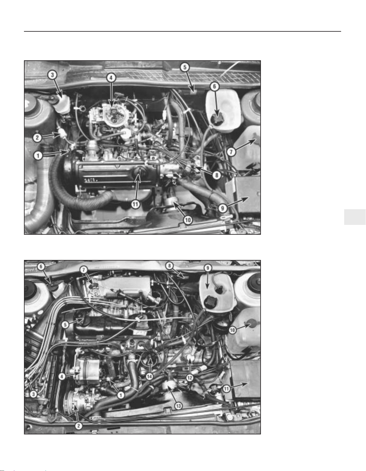
Underbonnet view – 1.3 litre model (air cleaner removed)
1 Engine oil dipstick
2 Fuel line filter
3 Brake master cylinder
reservoir
4 Carburettor
5 Ignition coil
6 Cooling system expansion
tank
7 Windscreen/headlight
washer reservoir
8 Ignition distributor
9 Battery
10Cooling fan
11Engine oil filler cap
Underbonnet view – fuel injection model
1 Engine oil dipstick
2 Compressor (air
conditioning)
3 Fuel distributor
4 Alternator
5 Engine oil filler cap
6 Brake master cylinder
reservoir
7 Throttle housing
8 Ignition coil
9 Cooling system expansion
tank
10Windscreen/headlamp
washer reservoir
11Battery
12Clutch cable
13Cooling fan
14Ignition distributor
Page 26
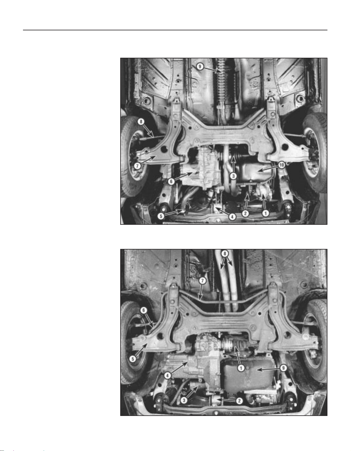
1•8 Maintenance - component location
1081 VW Golf & Jetta
Front underbody view - 1.3 litre model
1 Alternator
2 Oil filter
3 Driveshaft
4 Front mounting
5 Cooling system bottom
hose
6 Gearbox
7 Track control arm
8 Tie-rod
9 Exhaust
10Engine sump
Front underbody view - fuel injected model
1 Driveshaft
2 Front mounting
3 Starter motor
4 Gearbox
5 Track control arm
6 Tie-rod
7 Anti-roll bar
8 Exhaust system
9 Engine sump
Page 27
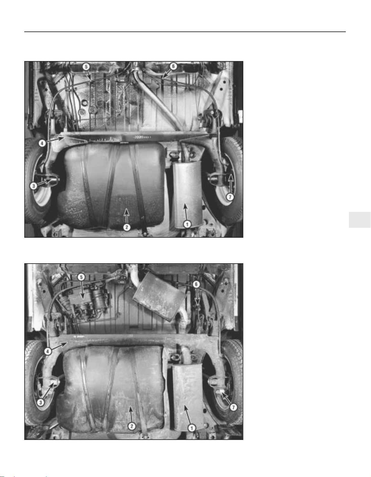
Maintenance - component location 1•9
1
1081 VW Golf & Jetta
Rear underbody view - 1.3 litre model
1 Exhaust
2 Fuel tank
3 Rear shock absorber lower
mounting
4 Axle beam
5 Handbrake cable (right-
hand)
6 Handbrake cable (left-hand)
7 Rear drum brake
Rear underbody view - fuel injected model
1 Exhaust
2 Fuel tank
3 Rear shock absorber lower
mounting
4 Axle beam
5 Fuel pump and associated
fittings
6 Brake pressure regulator
7 Rear disc brake
Page 28
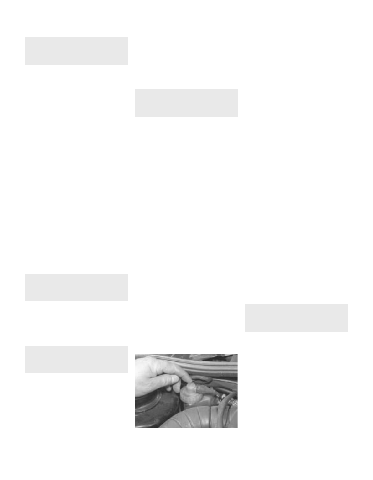
1 Introduction
This Chapter is designed to help the home
mechanic maintain his/her vehicle for safety,
economy, long life and peak performance.
The Chapter contains a master
maintenance schedule, followed by Sections
dealing specifically with each task in the
schedule. Visual checks, adjustments,
component renewal and other helpful items
are included. Refer to the accompanying
illustrations of the engine compartment and
the underside of the vehicle for the locations
of the various components.
Servicing your vehicle in accordance with
the mileage/time maintenance schedule and
the following Sections will provide a planned
maintenance programme, which should result
in a long and reliable service life. This is a
comprehensive plan, so maintaining some
items but not others at the specified service
intervals, will not produce the same results.
As you service your vehicle, you will
discover that many of the procedures can and should - be grouped together, because of
the particular procedure being performed, or
because of the close proximity of two
otherwise-unrelated components to one
another. For example, if the vehicle is raised
for any reason, the exhaust can be inspected
at the same time as the suspension and
steering components.
The first step in this maintenance
programme is to prepare yourself before the
actual work begins. Read through all the
Sections relevant to the work to be carried
out, then make a list and gather together all
the parts and tools required. If a problem is
encountered, seek advice from a parts
specialist, or a dealer service department.
2 Intensive maintenance
1 If, from the time the vehicle is new, the
routine maintenance schedule is followed
closely, and frequent checks are made of fluid
levels and high-wear items, as suggested
throughout this Manual, the engine will be
kept in relatively good running condition, and
the need for additional work will be minimised.
2 It is possible that there will be times when
the engine is running poorly due to the lack of
regular maintenance. This is even more likely
if a used vehicle, which has not received
regular and frequent maintenance checks, is
purchased. In such cases, additional work
may need to be carried out, outside of the
regular maintenance intervals.
3 If engine wear is suspected, a compression
test will provide valuable information
regarding the overall performance of the main
internal components. Such a test can be used
as a basis to decide on the extent of the work
to be carried out. If, for example, a
compression test indicates serious internal
engine wear, conventional maintenance as
described in this Chapter will not greatly
improve the performance of the engine, and
may prove a waste of time and money, unless
extensive overhaul work is carried out first.
4 The following series of operations are those
most often required to improve the
performance of a generally poor-running
engine:
Primary operations
a) Clean, inspect and test the battery
b) Check all the engine-related fluids
c) Check the condition and tension of the
auxiliary drivebelt
d) Renew the spark plugs
e) Inspect the distributor cap and HT leads -
as applicable
f) Check the condition of the air cleaner
filter element, and renew if necessary
g) Renew the fuel filter (if fitted)
h) Check the condition of all hoses, and
check for fluid leaks
i) Check the idle speed and mixture settings
- as applicable
5 If the above operations do not prove fully
effective, carry out the following secondary
operations:
Secondary operations
a) Check the charging system
b) Check the ignition system
c) Check the fuel system
d) Renew the distributor cap and rotor arm -
as applicable
f) Renew the ignition HT leads - as applicable
3 Lock, hinge and latch
mechanism check
1
Check the security and operation of all
hinges, latches and locks.
Check the condition and operation of the
tailgate struts, renewing them if either is
leaking or is no longer able to support the
tailgate securely when raised.
4 Seat belt check
1
1 Check the webbing of each belt for signs of
fraying, cuts or other damage, pulling the belt
out to its full extent to check its entire length.
Check the operation of the buckles by fitting
the belt tongue plate and pulling hard to ensure
that it remains locked, then check the retractor
mechanism (inertia reel only) by pulling out the
belt to the halfway point and jerking hard. The
mechanism must lock immediately to prevent
any further unreeling but must allow free
movement during normal driving.
2 Ensure that all belt mounting bolts are
securely tightened. Note that the bolts are
shouldered so that the belt anchor points are
free to rotate.
3 If there is any sign of damage, or any doubt
about a belt’s condition, it must be renewed.
If the vehicle has been involved in a collision
any belts in use at the time must be renewed
as a matter of course and all other belts
should be checked carefully.
4 Use only warm water and non-detergent
soap to clean the belts. Never use any
chemical cleaners, strong detergents, dyes or
bleaches. Keep the belts fully extended until
they have dried naturally; do not apply heat to
dry them.
5 Brake check
1
1 Make sure that the vehicle does not pull to
one side when braking and that the wheels do
not lock prematurely when braking hard.
2 Check that there is no vibration through the
steering when braking.
3 Check that the handbrake operates
correctly without excessive movement of the
lever and that it holds the vehicle stationary
on a slope.
4 Check the brake warning device for correct
operation by switching the ignition on and
releasing the handbrake. Now press the
contact on the reservoir filler cap down and
get an assistant to check that the handbrake
and dual circuit warning lamp light up (see
illustration).
1•10 Maintenance procedures
5.4 Check brake fluid level warning device
1081 VW Golf & Jetta
Every 1000 miles (1500 km) or monthly
Page 29
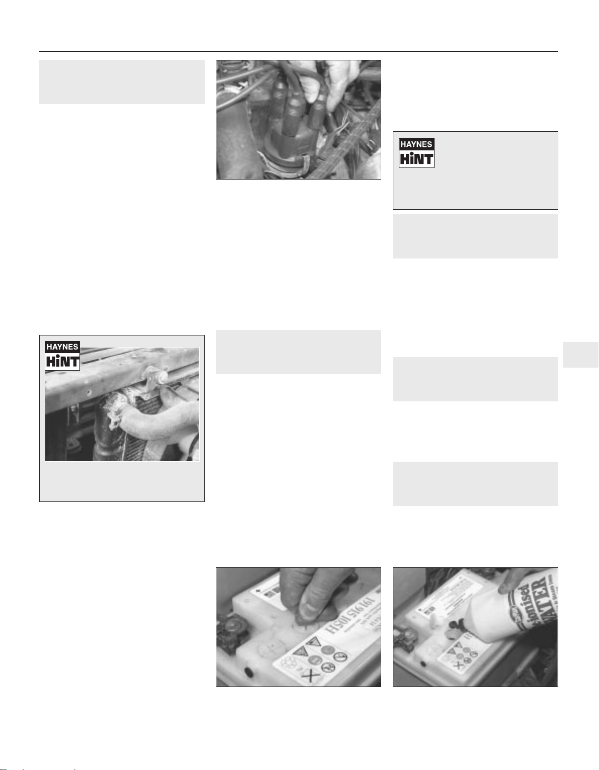
6 Fluid leakage and engine
electrical system check
1
1 Open the bonnet and inspect the engine
joint faces, gaskets and seals for any signs of
coolant or oil leaks. Pay particular attention to
the areas around the rocker cover, cylinder
head, oil filter and sump joint faces. Bear in
mind that over a period of time some very
slight seepage from these areas is to be
expected but what you are really looking for is
any indication of a serious leak. Should a leak
be found, renew the offending gasket or oil
seal.
2 Carefully check the condition and security
of all under bonnet coolant, fuel, power
steering and brake pipes and hoses. Renew
any hose which is cracked, swollen or
deteriorated. Cracks will show up better if the
hose is squeezed. Pay close attention to the
hose clips that secure the hoses to the system
components. Hose clips can pinch and
puncture hoses, resulting in leaks. If wire type
hose clips are used, it may be a good idea to
replace them with screw-type clips (see
Haynes Hint).
3 Check the condition of all exposed wiring
harnesses. Ensure that all cable-ties are in
place and in good condition. Ties which are
broken or missing can lead to chafing of the
wiring which could cause serious problems in
the future.
4 Wipe away any dirt which has accumulated
on the outside of the alternator and check that
its cable connector is pushed firmly onto its
terminals.
5 Clean the ignition system HT and LT leads
by wiping along their length with a fuelmoistened cloth. Inspect each lead for
damage and renew if defective in any way.
Ensure that all lead connections are secure
and where applicable, protected (see
illustration).
6 Check that all HT and LT leads are correctly
routed and clear of moving or hot engine
components.
7 Any corroded HT or LT lead connection
must be cleaned. A smear of petroleum jelly
(not grease) applied to the cleaned
connection will help to prevent further
corrosion.
8 Check the transmission for obvious oil
leaks and investigate and rectify any problems
found.
9 Where accessible, inspect the fuel filler
neck for punctures, cracks and other damage.
Sometimes a rubber filler neck or connecting
hose will leak due to loose retaining clamps or
deteriorated rubber.
7 Battery electrolyte level
check
2
1 A “maintenance-free” (sealed for life)
battery is standard equipment on all vehicles
covered by this Manual. Although this type of
battery has many advantages over the older
refillable type and should never require the
addition of distilled water, it should still be
routinely checked. The electrolyte level can be
seen through the battery’s translucent case
and must be between the MINIMUM and
MAXIMUM level marks. Although it should not
alter in normal use, if the level has lowered (for
example, due to electrolyte having boiled
away as a result of overcharging) it is
permissible to gently prise up the cell cover(s)
and to top-up the level.
2 If a conventional battery has been fitted as
a replacement, the electrolyte level of each
cell should be checked and, if necessary,
topped up until the separators are just
covered. On some batteries the case is
translucent and incorporates MINIMUM and
MAXIMUM level marks. The check should be
made more often if the vehicle is operated in
high ambient temperature conditions.
3 Top-up the electrolyte level using distilled
or de-ionised water (see illustrations).
8 Air conditioning system
check
1
During winter months, operate the air
conditioner for a few minutes each week to
keep the system in good order.
Check that the condenser is free of dirt and
insects. If necessary, clean it either by rinsing
with a cold water hose or by blowing it clean
with an air hose. Use a soft bristle brush to
assist removal of dirt jammed in the
condenser fins.
9 Fuel system control linkage
check
1
Check all parts of the fuel system control
linkage for free movement throughout its
complete operating range.
Clean all linkage joints and then lubricate
with a light machine oil.
10 Light, direction indicator and
horn check
1
Check that the horn and all vehicle lights
are functioning correctly. Renew any defective
bulbs.
The headlights and (where applicable) the
foglights should be in correct alignment.
Every 1000 miles or monthly 1•11
1
6.5 Ensure all HT lead connections are
secure
7.3a Remove battery filler caps . . . 7.3b . . . and top up electrolyte level using
distilled or de-ionised water
1081 VW Golf & Jetta
A leak in the cooling system will usually
show up as white or rust coloured
deposits on the area adjoining the leak
If regular topping-up becomes necessary and the
battery case is not fractured,
the battery is being overcharged and the voltage regulator
and/or alternator will have to be
checked.
Page 30
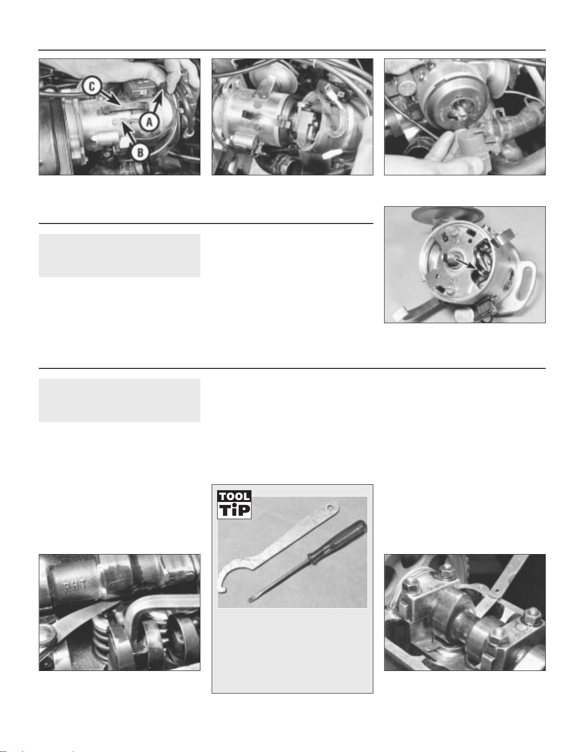
11 Contact breaker point check
2
1 Disconnect the LT lead from the terminal
block on the screening ring, then the earth
strap spade connector on the distributor body
(see illustration).
2 Release the two retaining clips and withdraw
the distributor cap, complete with screen ring,
from the distributor (see illustration).
3 Pull off the rotor arm and remove the dust
cover (see illustration).
4 Using a screwdriver, prise open the points
and inspect the condition of their faces (see
illustration). If they are pitted and
discoloured, remove them and dress them
using emery tape or a grindstone whilst
ensuring that their surfaces are flat and
parallel. If the points are worn excessively,
renew them. If the points are in good
condition, then check their adjustment.
12 Valve clearance check
3
1.05 and 1.3 litre engines
1 Run the engine up to its normal operating
temperature. Stop the engine and remove the
valve cover.
2 Turn the engine until both cam peaks for No
1 cylinder are pointing upwards.
3 Insert a feeler blade of the correct thickness
(specified “Warm” clearance) between the
cam and cam follower. If the blade is not a
firm sliding fit, proceed as follows:
4 Turn the adjustable ball-stud using an Allen
key (see illustration) . The valves from the
timing belt end of the engine are in the
following order:
Inlet - Exhaust - Inlet - Exhaust - Inlet -
Exhaust - Inlet - Exhaust
5 Repeat the procedure given in paragraphs
2 and 3 for the remaining valves. If the engine
is rotated in its normal direction, adjust the
valves of No 3 cylinder followed by No 4
cylinder and No 2 cylinder.
6 Refit the valve cover, together with a new
gasket.
1.6 and 1.8 litre 8 valve engines
Note: Ideally VW tools 2078 and 10.208
should be used to remove the valve shims, but
alternatives can be used (see Tool Tip)
Note: The following procedure applies only to
engines fitted with shim bucket tappets - that
is, those manufactured before August, 1985
7 Run the engine up to its normal operating
temperature. Stop the engine and remove the
valve cover.
8 Check each valve clearance in turn by
rotating the engine so that the valve to be
checked has the cam lobe facing upwards. In
this position, the valve in question is fully
closed and a feeler blade inserted between
the heel of the cam lobe and the valve tappet
shim within the tappet bucket will give the
clearance present (see illustration).
1•12 Maintenance procedures
12.4 Adjusting a valve clearance -
1.05 and 1.3 litre
12.8 Checking a valve clearance -
1.6 and 1.8 litre
11.1 Disconnect LT lead (A) earth strap (B)
and release securing clips (C)
11.2 Withdraw distributor cap and screen
ring
11.3 Pull off the rotor arm
11.4 Contact breaker points viewed
through window in bearing plate (arrowed)
- Ducellier
1081 VW Golf & Jetta
Every 5000 miles (7500 km) or 6 months
Every 10 000 miles (15 000 km) or 12 months
Ideally VW tools 2078 and 10.208 should
be used to remove the valve shims, but
we managed quite well with these
tools; a small electrician’s screwdriver
and a C-spanner which was just the
right size to push the bucket down
without pushing the tappet shim (ie
pushing the rim down).
Page 31
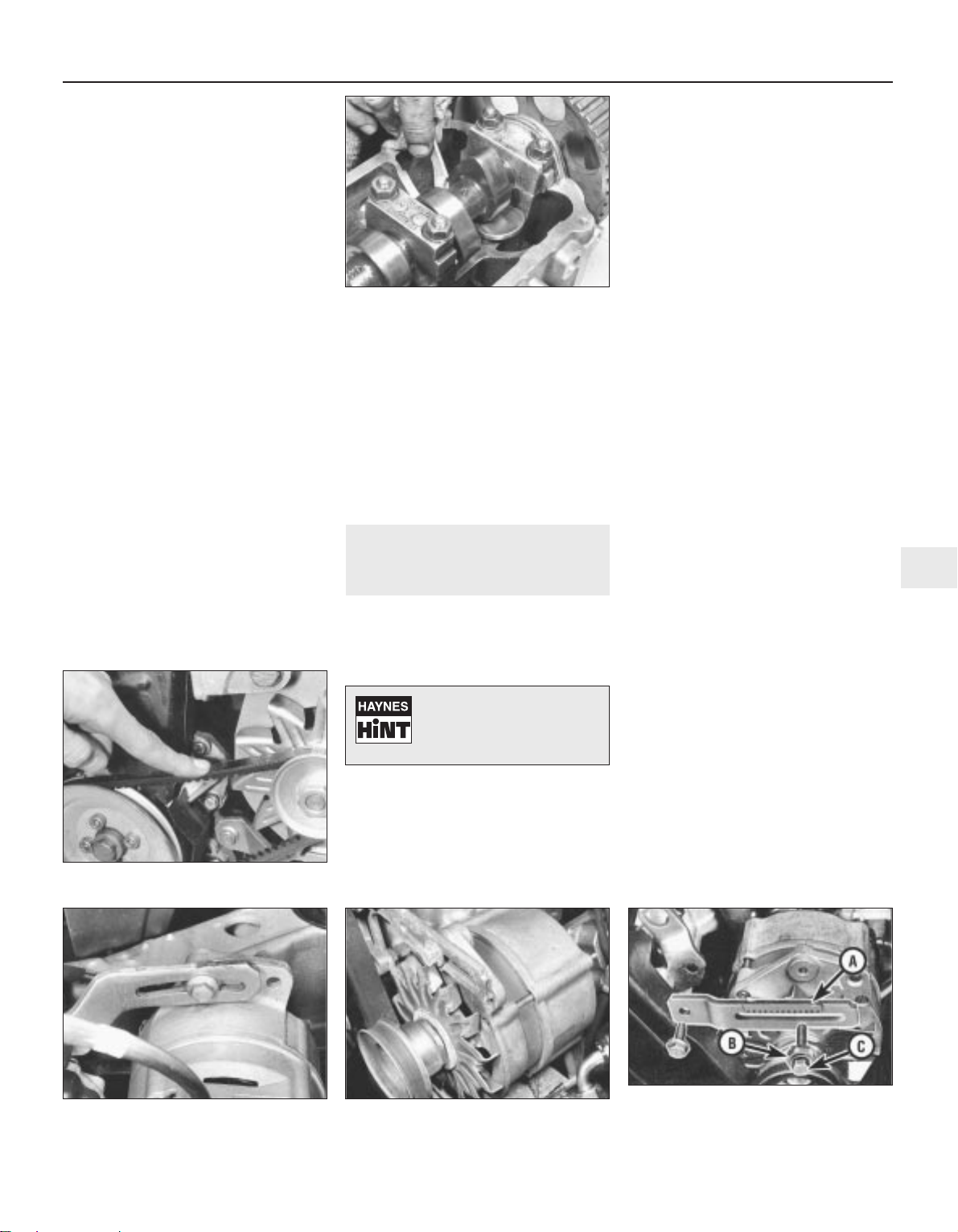
9 The engine will turn over more easily if the
spark plugs are removed. Do not rotate the
engine by turning the camshaft sprocket as
this will stretch the timing belt. Use the
alternator drivebelt (V-belt) or jack up one front
wheel and with the engine in gear rotate the
roadwheel. Do not turn the engine with any of
the shims removed, otherwise the camshaft
may foul the rim at the top of the bucket.
10 Repeat this measurement for all valves in
turn and then compare the measurements
with those specified (“Warm” clearance).
11 Make a table of the actual clearances and
then calculate the error from those specified.
Suppose on No 1 exhaust valve, the measured
clearance is 0.15 mm. It is 0.3 mm too small so
it must be adjusted and a shim 0.3 mm thinner
fitted instead of the present one. As the shims
are in steps of 0.05 mm variation, the required
shim can be selected once the size of the shim
at present installed is known. If you have
dismantled and reassembled the head, then
you know the size etched on the back of the
shim but if you do not, then the shim must be
removed to find out.
12 With the cam turned to give maximum
clearance, the tappet is pushed down against
the valve springs while the shim is levered out
and removed by the VW tool or a screwdriver.
Be careful, because if the spanner slips when
the shim is halfway out, the shim will fly out
sharply (see illustration).
13 Once all the shim sizes are known, a table
may be constructed and the sizes of the new
shims required may be calculated. Going back
to the example, if the present shim is marked
3.60 then one marked 3.30 is required. Bucket
shims are available in 26 different thicknesses
which increase in increments of 0.05 mm, from
3.00 mm to 4.25 mm.
14 As it is unlikely that you will have the
required shims readily available, it will be
necessary to wait until they have been
obtained before the tappets can be adjusted.
15 When inserting the shims, the thickness
etching faces should be facing downwards.
16 Once the correct clearances have been
achieved, refit the spark plugs and the valve
cover.
13 Alternator, power steering
pump and air conditioner
compressor drivebelt(s) check
2
1 Check all drivebelts along their full length
for cracks, splitting, fraying or damage. Check
also for signs of glazing (shiny patches) and
for separation of the belt plies. Renew the belt
if worn or damaged.
Alternator
Pre 1985
2 Depress the alternator drivebelt firmly with
a finger midway between the alternator and
crankshaft pulleys (see illustration). The belt
should deflect approximately 5.0 mm.
3 If a new drivebelt has been fitted, then initial
adjustment should give a deflection of 2.0 mm.
After a suitable running in period of about 500
miles (750 km), belt adjustment should be
rechecked and adjusted to deflect 5.0 mm.
4 To adjust the drivebelt, loosen the nut on
the adjusting link and pivot bolt (see
illustrations), then lever the alternator away
from the cylinder block by using a lever at the
pulley end of the alternator, until the belt is
tensioned correctly.
5 Tighten the nut and bolt on completion of
drivebelt adjustment.
From 1985
6 From early 1985, some models are fitted
with a rack type alternator adjustment link
(see illustration). To adjust drivebelt tension,
first fully loosen the adjustment locknut and
bolt, the link pivot bolt and the alternator pivot
bolt, so that the alternator falls to one side
under its own weight.
7 Using a socket and torque wrench on the
adjustment bolt, apply a torque of 8 to 10 Nm
(6 to 7 Ibf ft), then secure the adjustment bolt
in the set position by tightening its locknut to
35 Nm (26 Ibf ft).
8 If the special VW tool is being used, then
the adjustment bolt can now be tightened. If
not, tighten the pivot bolt then remove the
socket and immediately tighten the
adjustment bolt, making sure that the
alternator does not move.
9 Tighten the link pivot bolt and alternator
pivot bolt.
Power steering pump
10 Loosen the power steering pump unit
retaining nuts and bolts and the adjuster bolt
locknut on the pump bracket.
11 Turn the tensioning bolt until the belt can
be depressed approximately 10.0 mm under
firm finger pressure midway between the
crankshaft and pump pulleys.
12 When tension is correct, tighten the
adjusting bolt locknut and the pump retaining
nuts and bolts.
Air conditioner compressor
13 Drivebelt tension is adjusted by adding or
subtracting shims from between the halves of
the compressor pulley.
14 When correctly adjusted, the belt should
give a deflection of 5 to 10 mm on its longest
run.
Every 10 000 miles or 12 months 1•13
1
12.12 Removing a tappet bucket shim -
1.6 and 1.8 litre
13.2 Checking alternator drivebelt tension
13.4a Alternator drivebelt tensioner link -
1.3 litre
13.4b Alternator drivebelt tensioner link -
1.8 litre
13.6 Rack type alternator drivebelt
tensioner link (A) locknut (B) and
adjustment bolt (C)
1081 VW Golf & Jetta
Always recheck the tension
of a new drivebelt after the
engine has been run for ten
minutes.
Page 32
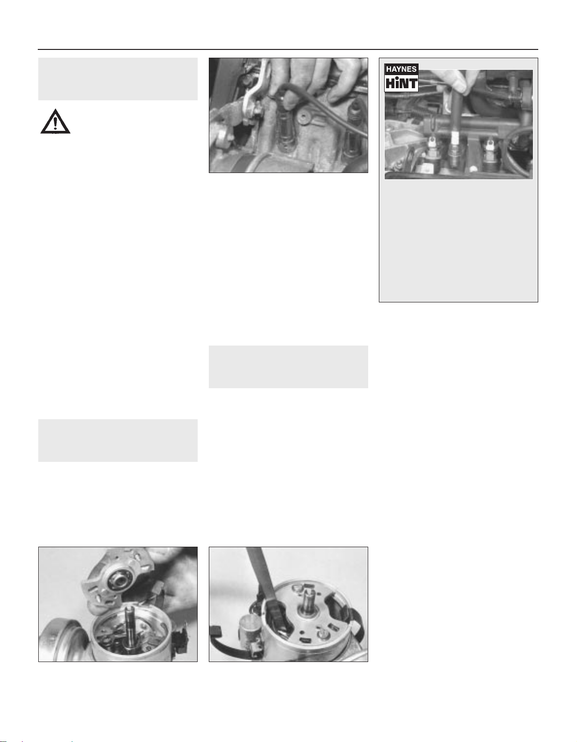
14 Antifreeze concentration
check
2
Warning: Wait until the engine is
cold before checking antifreeze.
Do not allow antifreeze to come
in contact with your skin or
painted surfaces of the vehicle. Rinse off
spills immediately with plenty of water.
Never leave antifreeze lying around in an
open container or in a puddle in the
driveway or on the garage floor. Children
and pets are attracted by its sweet smell.
Antifreeze is fatal if ingested.
1 The concentration of antifreeze in the
cooling system should be checked and made
good if necessary. Most garages can do this
check, or an instrument similar to a battery
hydrometer can be purchased for making the
check at home.
2 It is essential that an antifreeze mixture is
retained in the cooling system at all times to
act as a corrosion inhibitor and to protect the
engine against freezing in winter months. The
mixture should be made up from clean water
with a low lime content (preferably rainwater)
and a good quality ethylene glycol based
antifreeze which contains a corrosion inhibitor
and is suitable for use in aluminium engines.
3 The proportion of antifreeze to water must
be 50/50 and give protection down to
approximately -30ºC.
4 In climates which render frost protection
redundant, it is still necessary to use a
corrosion inhibitor in the cooling system.
Suitable inhibitors should be available from a
local VW agent or other reputable specialist.
15 Spark plug renewal
2
Note: Some models are fitted with a modified
ignition coil and single earth electrode spark
plugs. This modified coil is identified by a grey
(rather than green) sticker. Refer to the
Servicing Specifications at the start of this
Chapter for the recommended plug types. It is
not permissible to use new plugs with an old
coil, or vice versa.
1 Where applicable, remove the air cleaner.
2 Pull the HT lead and fittings from each
spark plug, identifying them for location if
necessary (see illustration). On the 16V
engine, the end fittings incorporate
extensions, as the plugs are deeply recessed
in the cylinder head.
3 Using compressed air or a vacuum cleaner,
remove any debris from around the spark
plugs.
4 Unscrew the plugs using a plug socket,
preferably with a rubber insert to grip the plug.
5 Refitting is a reversal of removal. Tighten
each spark plug to the specified torque (see
Haynes Hint).
16 Contact breaker point
renewal and adjustment
3
Renewal
1 Disconnect the LT lead from the terminal
block on the screening ring, then the earth
strap spade connector on the distributor
body.
2 Release the two retaining clips and
withdraw the distributor cap, complete with
screen ring, from the distributor.
3 On 1.05 and 1.3 litre engines, remove the
screws and withdraw the bearing plate (see
illustration).
4 Disconnect the moving contact LT lead
from the terminal then remove the retaining
screw and withdraw the contact breaker set
from the distributor.
5 Wipe clean the contact breaker plate in the
distributor and make sure that the contact
surfaces of the new contact breaker set are
clean. Lubricate the arm surface and moving
contact pivot with a little multi-purpose
grease. Use only a small amount, otherwise
the contact points may become contaminated.
6 Fit the contact set on the baseplate and
refit the retaining screw. Connect the LT lead
to the terminal.
7 Refit the bearing plate and tighten the
screws (where applicable).
8 Adjust the contact breaker points as
follows.
Adjustment
9 Turn the engine with a spanner on the
crankshaft pulley bolt until the moving contact
point is fully open with its contact heel on the
peak of one of the cam lobes.
10 Using a feeler blade, check that the gap
between the two points is as specified. If not,
loosen the fixed contact screw and reposition
the fixed contact until the feeler blade is a firm
sliding fit between the two points. In order to
make a fine adjustment, slightly loosen the
screw then position the screwdriver in the
fixed contact notch and the two pips on the
contact plate. With the gap adjusted, tighten
the screw (see illustrations).
11 Using a dwell meter, check that the dwell
angle of the contact points is as specified
while spinning the engine on the starter. If not,
readjust the points gap as necessary. Reduce
the gap in order to increase the dwell angle, or
increase the gap in order to reduce the dwell
angle.
12 Clean the dust cover and rotor arm then
refit them. Do not remove any metal from the
rotor arm segment.
1•14 Every 10 000 miles or 12 months
15.2 Hold the suppresser cap when pulling
each HT lead from its spark plug
16.3 Removing the bearing plate -
1.05 and 1.3 litre
16.10a Checking contact breaker points
gap
1081 VW Golf & Jetta
It is very often difficult to insert spark
plugs into their holes without crossthreading them. To avoid this possibility, fit a short length of 5/16 inch
internal diameter rubber hose over the
end of the spark plug. The flexible hose
acts as a universal joint to help align
the plug with the plug hole. Should the
plug begin to cross-thread, the hose
will slip on the spark plug, preventing
thread damage to the aluminium
cylinder head.
Page 33
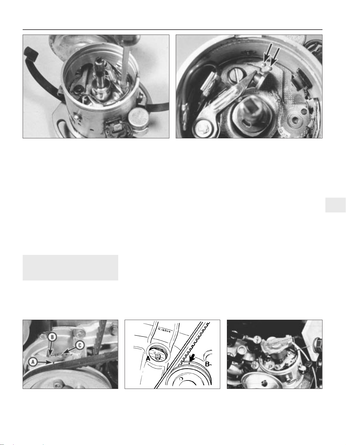
13 Wipe clean the distributor cap and make
sure that the carbon brush moves freely
against the tension of the spring. Clean the
metal segments in the distributor cap but do
not scrape away any metal, otherwise the HT
spark at the spark plugs will be reduced. Also
clean the HT leads and coil tower.
14 Refit the distributor cap and interference
screen.
15 Start the engine and check that the dwell
angle is as specified, both at idling and higher
engine speeds. A decrease in dwell angle at
high engine speeds indicates a weak spring
on the moving contact points.
16 After making any adjustment to the
contact breaker points, check and adjust the
ignition timing.
17 Ignition timing check
3
Contact breaker system
Note: Accurate ignition timing is only possible
using a stroboscopic timing light, although on
some models a DC sender unit is located on
the top of the gearbox casing and may be
used with a special VW tester to give an
instant read-out. However, this tester will not
normally be available to the home mechanic.
For initial setting-up purposes, the test bulb
method can be used but this must always be
followed by the stroboscopic timing light
method
Test bulb method
1 Remove No. 1 spark plug (crankshaft pulley
end) and place a thumb over the aperture.
2 Turn the engine in the normal running
direction (clockwise viewed from the
crankshaft pulley end) until pressure is felt in
No. 1 cylinder, indicating that the piston is
commencing its compression stroke. Use a
spanner on the crankshaft pulley bolt, or
engage top gear and pull the vehicle forwards.
3 Continue turning the engine until the line on
the crankshaft pulley is aligned with the
pointer on the timing cover. If there are no
marks on the timing cover, unscrew and
remove the DC sensor or blanking plug from
the top of the gearbox and align the timing
mark (see Specifications) with the timing
pointer (see illustrations).
4 Remove the distributor cap and check that
the rotor arm is pointing toward the No. 1 HT
lead location in the cap.
5 Connect a 12 volt test bulb between the coil
LT negative terminal and a suitable earthing
point on the engine.
6 Loosen the distributor clamp retaining bolt.
7 Switch on the ignition. If the bulb is already
lit, turn the distributor body slightly clockwise
until the bulb goes out.
8 Turn the distributor body anti-clockwise
until the bulb just lights up, indicating that the
points have just opened. Tighten the clamp
retaining bolt.
9 Switch off the ignition and remove the test
bulb.
10 Refit the distributor cap and No. 1 spark
plug and HT lead. Once the engine has been
started, check the timing stroboscopically.
Stroboscopic timing light method
11 Run the engine until its normal operating
temperature is reached.
12 On 1.05, 1.3 and 1.8 litre fuel injection
engines, disconnect and plug the distributor
vacuum hose.
13 If there are no timing marks on the timing
cover and crankshaft pulley, unscrew and
remove the TDC sensor or blanking plug from
the top of the gearbox.
14 Connect the timing light in accordance
with the manufacturer’s instructions.
Every 10 000 miles or 12 months 1•15
1
17.3a Crankshaft pulley mark (A) timing
mark (B) and TDC mark (C) (timing cover
removed) - 1.3 litre
17.3b TDC timing marks - 1.6 and 1.8 litre
A Flywheel/driveplate
B Crankshaft pulley
17.3c Rotor arm aligned with TDC mark on
distributor body – 1.6 and 1.8 litre
1081 VW Golf & Jetta
16.10b Adjusting contact breaker points gap
16.10c Two pips and notch (arrowed) for inserting screwdriver
when adjusting contact breaker points gap
Page 34
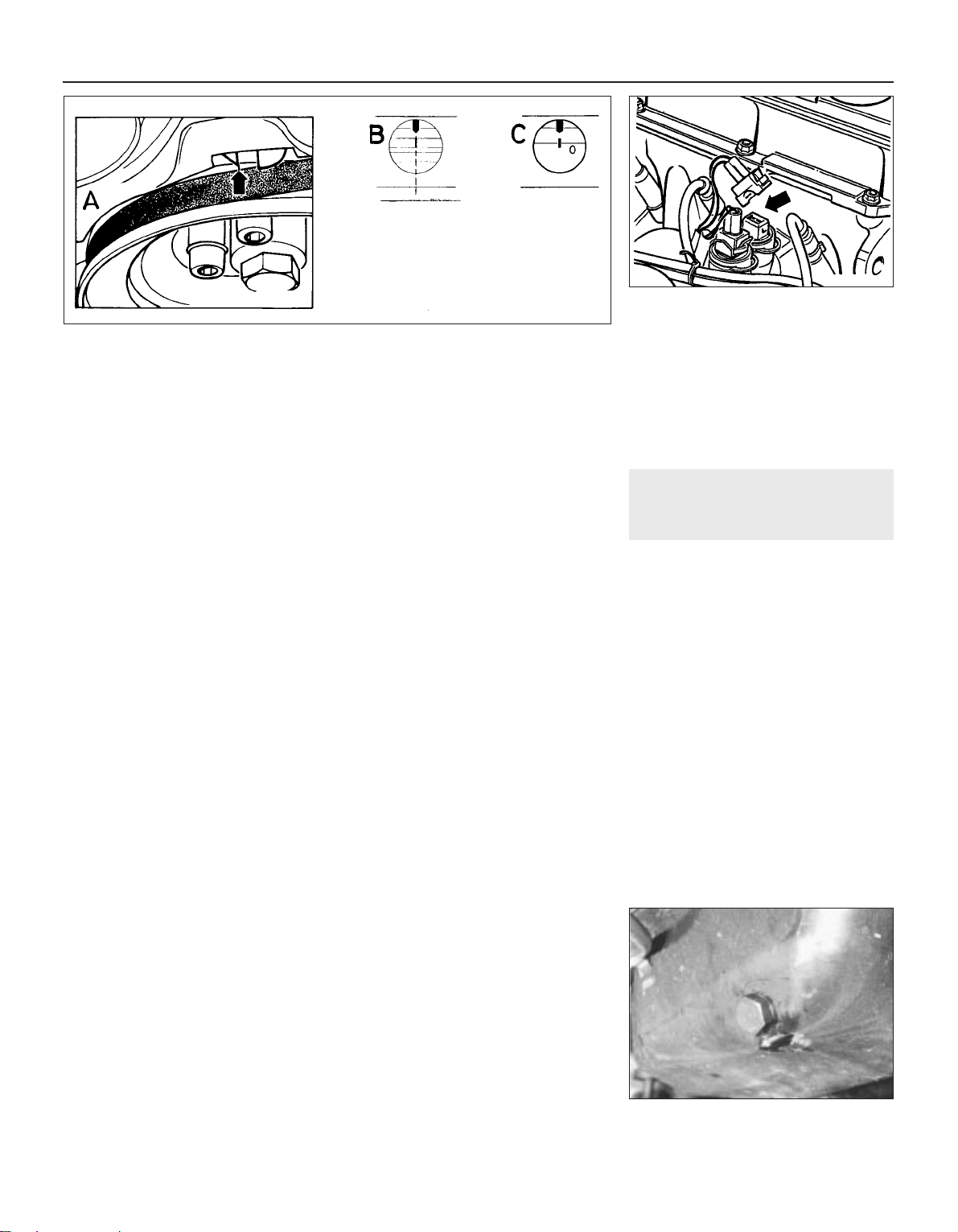
15 Connect a tachometer in accordance with
the manufacturer’s instructions.
16 Start the engine and run it at idling speed.
17 Point the timing light at the timing mark
and pointer which should appear to be
stationary and aligned. If adjustment is
necessary (ie. the marks are not aligned),
loosen the clamp retaining bolt and turn the
distributor body to correct the ignition timing
(see illustration).
18 Gradually increase the engine speed while
still pointing the timing light at the timing
marks. The mark on the flywheel or pulley
should appear to move opposite to the
direction of rotation, proving that the
centrifugal weights are operating correctly. If
not, the centrifugal mechanism is faulty and
the distributor should be renewed.
19 Accurate checking of the vacuum
advance (and retard where fitted) requires the
use of a vacuum pump and gauge. However,
providing that the diaphragm unit is
serviceable, the vacuum hose(s) firmly fitted,
and the internal mechanism not seized, the
system should work correctly.
20 Switch off the engine, remove the timing
light and tachometer, and refit the vacuum
hose (where applicable).
Transistorised systems
Note: Accurate ignition timing is only possible
using a stroboscopic timing light, although on
some models a DC sender unit is located on
the top of the gearbox casing and may be
used with a special VW tester to give an
instant read-out. However, this tester will not
normally be available to the home mechanic
TCI-H
21 Run the engine until its normal operating
temperature is reached.
22 On 1.05, 1.3 and 1.8 fuel injection
engines, disconnect and plug the distributor
vacuum hose.
23 If there are no timing marks on the timing
cover and crankshaft pulley, unscrew and
remove the TDC sensor or blanking plug from
the top of the gearbox.
24 Connect a timing light in accordance with
the manufacturer’s instructions.
25 Connect a tachometer in accordance with
the manufacturer’s instructions.
26 Start the engine and run it at idling speed.
27 Point the timing light at the timing mark
and pointer which should appear to be
stationary and aligned. If adjustment is
necessary (ie. the marks are not aligned),
loosen the clamp retaining bolt and turn the
distributor body to correct the ignition timing
(see illustration 17.17).
28 Gradually increase the engine speed while
still pointing the timing light at the timing
marks. The mark on the flywheel or pulley
should appear to move opposite to the
direction of rotation, proving that the
centrifugal weights are operating correctly. If
not, the centrifugal mechanism is faulty and
the distributor should be renewed.
29 Accurate checking of the vacuum
advance (and retard where fitted) requires the
use of a vacuum pump and gauge. However,
providing that the diaphragm unit is
serviceable, the vacuum hose(s) firmly fitted,
and the internal mechanism not seized, the
system should work correctly.
30 Switch off the engine, remove the timing
light and tachometer, and refit the vacuum
hose (where applicable).
Digifant
31 Run the engine to normal operating
temperature, then switch off the ignition.
32 Connect a stroboscopic timing light to the
engine.
33 Run the engine at idle speed.
34 Disconnect the wiring from the
temperature sender (see illustration).
35 Increase the engine speed to between 2000
and 2500 rpm, then point the timing light at the
aperture over the flywheel. The timing marks
should be aligned (see illustration 17.17), but if
not, loosen the clamp bolt, turn the distributor
as required and retighten the bolt.
36 While checking the ignition timing, the
opportunity should be taken to check the
temperature and knock sensor controls.
37 With the temperature sender wiring
disconnected, increase the engine speed to
2300 rpm and note the exact ignition timing.
Hold the engine speed at 2300 rpm, then
reconnect the wiring and check that the
ignition timing advances by 30° ± 3° from the
previously noted value.
38 If the ignition timing only advances about
20°, slacken the knock sensor securing bolt,
retighten to 20 Nm (15 Ibf ft) and repeat the
test. If there is no difference, check the
associated wiring for an open-circuit, or as a
last resort, renew the knock sensor.
39 If there is no advance in ignition timing,
check the temperature sender wiring for an
open-circuit. A fault is indicated in the Digifant
control unit if there is no open-circuit.
18 Engine oil and filter renewal
2
Oil renewal
1 Before starting this procedure, gather
together all necessary tools and materials.
Ensure that you have plenty of clean rags and
newspapers handy to mop up any spills.
Ideally, the engine oil should be warm as it will
drain better and more built-up sludge will be
removed with it. Take care not to touch the
exhaust or any other hot parts of the engine
when working under the vehicle. To avoid any
possibility of scalding and to protect yourself
from possible skin irritants and other harmful
contaminants in used engine oils, it is advisable
to wear gloves when carrying out this work.
2 With the vehicle standing on level ground,
position a suitable container under the sump
drain plug (see illustration). Remove the
drain plug from the sump.
3 Allow some time for the old oil to drain,
noting that it may be necessary to reposition
the container as the flow of oil slows to a
trickle. Work can be speeded-up by removing
1•16 Every 10 000 miles or 12 months
17.34 Disconnecting temperature sender
wire
18.2 Sump drain plug
1081 VW Golf & Jetta
17.17 Ignition timing marks
A 1.05 and 1.3 litre
B 1.6 and 1.8 litre (carburettor models)
C 1.8 litre (fuel injection models)
Page 35
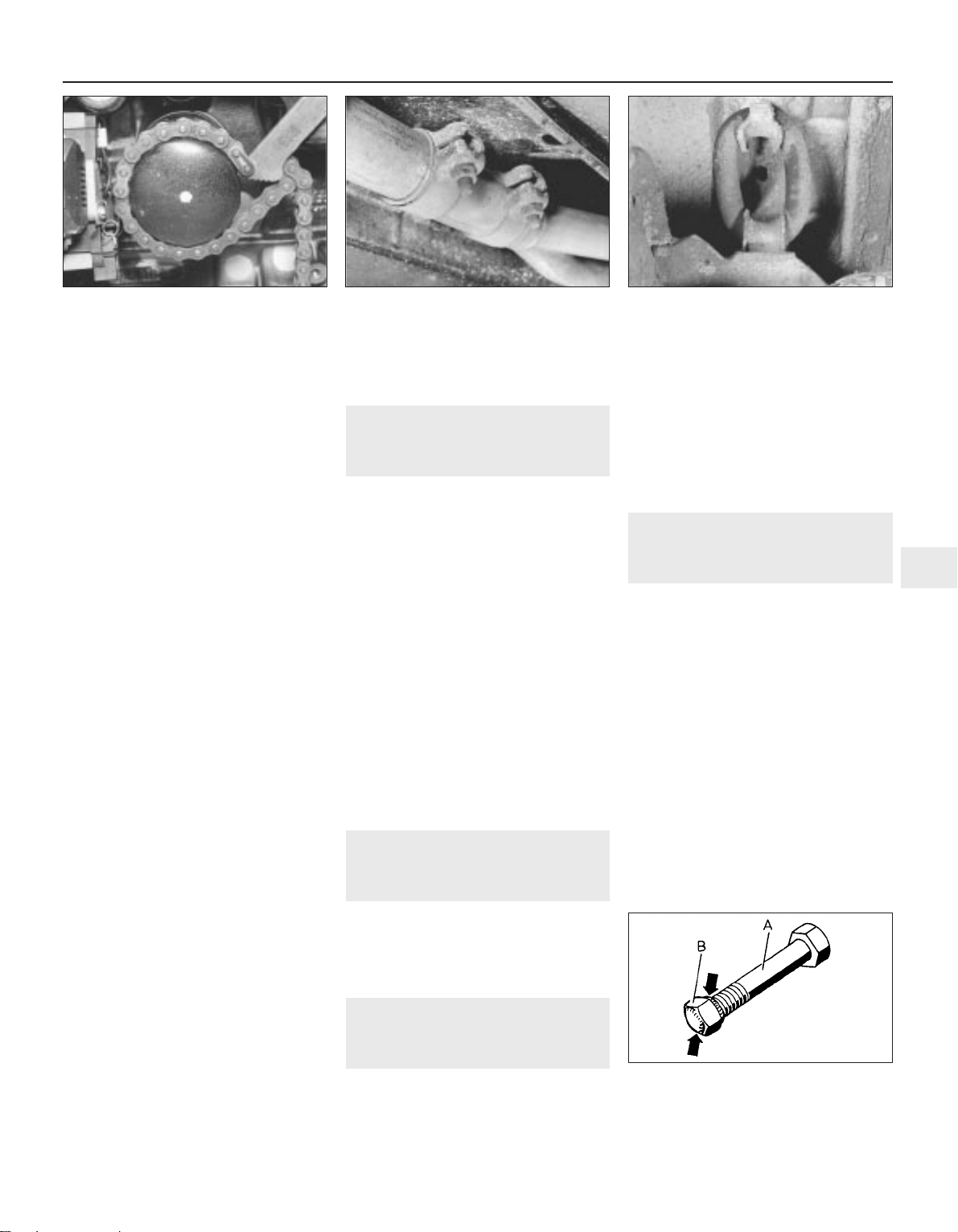
the oil filter, as described below, while the oil
is draining.
4 After all the oil has drained, wipe off the
drain plug with a clean rag and on 1.6 and 1.8
litre models, renew the O-ring. Clean the area
around the drain plug opening and refit the
plug. Tighten the plug to the specified torque
setting.
5 Depending on engine type, refer to the
following sub Section and renew the oil filter.
6 Remove the oil container and all tools from
under the vehicle.
7 Refill the engine with the specified type of
oil. Pour in half the specified quantity of oil
first, then wait a few minutes for the oil to
drain to the sump. Continue adding oil a small
quantity at a time until the level is up to the
lower mark on the dipstick (see Weekly
checks). Adding a further 1.0 litre will bring the
level up to the upper mark on the dipstick.
8 Start the engine and run it for a few minutes
while checking for leaks around the oil filter
seal and the sump drain plug.
9 Switch off the engine and wait a few
minutes for the oil to settle in the sump once
more. With the new oil circulated and the filter
now completely full, recheck the level on the
dipstick and add more oil as necessary.
10 Dispose of the used engine oil safely.
Filter renewal
11 On 1.05 and 1.3 litre engines, the oil filter
is located on the front of the engine beside the
alternator.
12 On 1.6 and 1.8 litre engines, the oil filter is
located on the side of the crankcase beneath
the distributor. It is screwed onto a mounting
bracket attached to the crankcase. On fuel
injection models, an oil cooler is fitted between
the mounting bracket and filter cartridge.
13 With the engine oil drained, place a
suitable container beneath the filter then,
using a suitable tool, unscrew the filter (see
illustration). Empty any oil in the old filter into
the container and allow any residual oil to
drain out of the engine.
14 Check the old filter to make sure that the
rubber sealing ring has not stuck to the
engine. If it has, then carefully remove it. Wipe
clean the sealing face on the cylinder block.
15 Smear the sealing rubber on the new filter
with clean engine oil, then fit and tighten the
filter by hand only.
16 On completion, replenish the engine oil
then wipe clean the filter body. When the
engine is restarted, check around the filter
joint for any signs of leakage.
19 Exhaust system check
1
1 With the exhaust system cold, check the
complete system from the engine to the end of
the tailpipe. Ideally the inspection should be
carried out with the vehicle raised and
supported on axle stands (see “Jacking and
vehicle support”) to permit unrestricted access.
2 Check the exhaust pipes and connections
for evidence of leaks, severe corrosion and
damage (see illustration). Ensure that all
brackets and mountings are in good condition
and tight. Leakage at any of the joints or in
other parts of the system will usually show up
as a black sooty stain in the vicinity of the leak.
3 Rattles and other noises can often be
traced to the exhaust system, especially the
brackets and mountings (see illustration). Try
to move the pipes and silencers. If the
components can come into contact with the
body or suspension parts, secure the system
with new mountings or if possible, separate
the joints and twist the pipes as necessary to
provide additional clearance.
20 Slow running adjustment
4
To check this adjustment, first determine
which fuel system is fitted to the vehicle
concerned and then refer to the appropriate
Part of Chapter 4 for adjustment of that
particular system.
21 Clutch operation check
2
1 Check that the clutch pedal moves
smoothly and easily through its full travel and
that the clutch itself functions correctly, with
no trace of slip or drag.
2 If excessive effort is required to operate the
clutch, check first that the cable is correctly
routed and undamaged, then remove the
pedal to ensure that its pivot is properly
greased before suspecting a fault in the cable
itself. If the cable is worn or damaged, or if its
adjusting mechanism is no longer effective,
then it must be renewed.
3 Refer to Chapter 6 and on those models
where it is possible, check that the clutch is
correctly adjusted.
22 Gearbox oil level check
2
Note: Gearbox oil can foam when hot and
give a false level reading. Allow the gearbox to
cool before checking the oil level.
1 The gearbox oil level must be checked
before the vehicle is driven, or at least 5
minutes after the engine has been switched
off. If the oil is checked immediately after
driving, some of the oil will remain distributed
around the gearbox components, resulting in
an inaccurate level reading.
084 and 085 gearboxes
2 Position the vehicle on level ground.
3 The oil filler/level plug is difficult to reach
using the normal hexagon key and it will be
much easier to use a nut and bolt as shown
(see illustration) together with a conventional
spanner. Instead of welding a single nut on
the bolt, two nuts may be tightened against
each other using thread-locking fluid.
Every 10 000 miles or 12 months 1•17
1
18.13 Using a chain wrench to unscrew oil
filter
19.2 Check exhaust system connections
for leaks and security
19.3 Check exhaust system mountings
22.3 Nut and bolt welded together to make
oil level plug removal tool - 084 gearbox
A Bolt M10 x 100 mm B Welded nut
Arrows show area of weld
1081 VW Golf & Jetta
Page 36
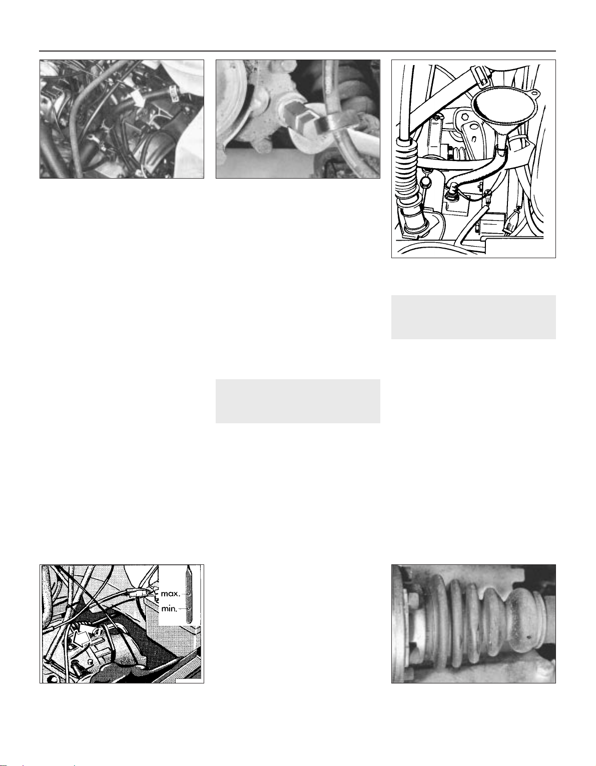
4 Wipe clean the area around the filler/level
plug, then unscrew the plug and clean it.
Discard the sealing washer (see illustration).
5 The oil level should reach the lower edge of
the filler/level hole. A certain amount of oil will
have gathered behind the plug and will trickle
out when it is removed - this does not
necessarily indicate that the level is correct.
To ensure that a true level is established, wait
until the initial trickle has stopped, then add oil
as necessary until a trickle of new oil can be
seen emerging. The level will be correct when
the flow ceases. Use only good quality oil of
the specified type.
6 If the gearbox has been overfilled so that oil
flows out as soon as the filler/level plug is
removed, check that the vehicle is completely
level (front-to-rear and side-to-side) and allow
the surplus to drain off into a suitable
container.
7 When the oil level is correct, fit a new
sealing washer and refit the filler/level plug,
tightening it to the specified torque wrench
setting. Clean away any spilt oil.
020 5-speed gearbox
8 Note the basic instructions given for the
084 and 085 gearboxes whilst taking into
account the following information.
9 This gearbox was originally designed for an
engine/gearbox unit without any inclination.
When fitted to the models covered in this
Manual a 2° inclination to the left exists,
therefore an accurate check cannot be made
with the vehicle on ground level.
10 When checking the oil level with the
vehicle on level ground, unscrew the level
plug (see illustration) and if there is a thick
flow of oil immediately refit the plug. If there is
no flow, first top-up to the bottom of the hole
then refit the plug.
11 Now add a further 0.5 litre of oil through
the speedometer driveshaft hole (see
illustration).
12 From October 1987, the oil level plug hole
has been relocated 7.0 mm higher than the
one on earlier models. Consequently all filling
and topping up can be carried out through the
oil level hole. Removal of the speedometer
drive cable is no longer necessary for final
topping up.
23 Automatic transmission fluid
level check
1
1 Check the transmission fluid level with the
engine warm and idling, with the selector lever
in position N (neutral) and the handbrake
firmly applied.
2 With the vehicle on a level surface,
withdraw the level dipstick and wipe it clean
with a lint-free cloth. Reinsert it and withdraw
again. The level must be between the two
marks on the dipstick (see illustration). If not,
top-up the level through the dipstick tube
using the specified fluid.
3 If much topping-up is required, carry out a
check for leaks. If no external leaks are visible,
check the final drive oil level. If this is found to
be too high, it is probable that the
transmission fluid is leaking internally into the
final drive casing and if this is the case, it must
be attended to without delay by your VW
dealer.
4 The difference in quantity of fluid between
the maximum and minimum marks on the fluid
level dipstick is 0.4 litre.
5 On completion, insert the dipstick and
switch off the engine.
24 CV joint and boot check
1
1 With the vehicle raised and supported on
axle stands (see “Jacking and vehicle
support”), turn the steering onto full lock then
slowly rotate each roadwheel in turn to
facilitate inspection of the CV joints and boots.
2 Inspect the condition of each CV joint boot
while squeezing it to open out any folds (see
illustration). Check for signs of cracking,
splits or deterioration of the rubber which may
allow grease to escape and lead to the entry
of water and grit into the joint. Also check the
security and condition of the boot retaining
clips. If any damage or deterioration is found,
the boot should be renewed.
3 At the same time, check the general
condition of the CV joints themselves by first
holding the driveshaft and attempting to
rotate the roadwheel. Repeat this check by
holding the inner joint and attempting to rotate
the driveshaft. Any appreciable movement
indicates wear in the joints, in the driveshaft
splines, or a loose driveshaft nut.
1•18 Every 10 000 miles or 12 months
22.4 Gearbox filler/level plug location
(arrowed) - 084 gearbox
22.10 Using a key to unscrew level plug 020 5-speed gearbox
22.11 Filling gearbox through
speedometer driveshaft hole - early 020
5-speed gearbox
23.2 Automatic transmission fluid level
dipstick - remove in direction of arrow
24.2 Inspect condition of each CV joint
boot
1081 VW Golf & Jetta
Page 37
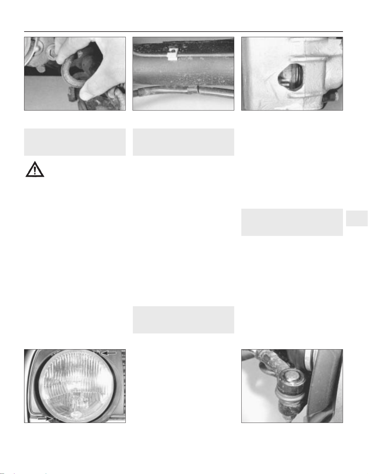
25 Fuel and brake line, hose
and union check
1
Warning: Do not drive the
vehicle until necessary repair
work has been carried out on
damaged fuel and brake lines.
1 It is essential for this check to raise the
vehicle sufficiently enough to allow a
complete uninterrupted view of its underside.
2 Working methodically from one end of the
vehicle to the other, carry out the following
tasks.
3 Clean the rigid brake lines and flexible
hoses, at the same time checking them for
damage, leakage, chafing and cracks. If the
coating on the rigid pipes is damaged or if
rusting is apparent, then they must be
renewed. Check all pipe retaining clips for
security and clean away any accumulation of
dirt (see illustrations).
4 Similarly, inspect all hoses and metal pipes
leading away from the fuel tank. Pay particular
attention to the vent pipes and hoses which
often loop up around the tank filler neck and
can become blocked or crimped.
5 Inspect the underside of the fuel tank for
punctures, scrapes and other damage.
6 If any damage or deterioration is discovered
to either system, do not drive the vehicle until
the necessary repair work has been carried
out.
26 Brake pad and rear shoe
lining check
1
Note: VW recommend that operation of the
brake pressure regulator is checked by one of
their garages at the same interval that the disc
pads and rear brake linings are checked for
wear
Brake pads
1 Both front and rear brake pad lining wear
can be checked by viewing through a hole in
the wheel rim (see illustration). Use a mirror
placed on the inside of the wheel. The use of a
torch may also be necessary.
2 If pad thickness is less than the minimum
amount specified, renew the pads as a set.
Rear brake shoes
3 Jack up the rear of the vehicle and support
it on axle stands (see “Jacking and vehicle
support”). Chock the front wheels.
4 Working beneath the vehicle, remove the
rubber plugs from the front of the backplates
and check with a torch that the linings are not
worn below the minimum thickness specified.
On completion, refit the plugs.
27 Headlight beam alignment
check
3
Single unit
Caution: It is recommended that headlamp
beam alignment is checked by a VW
garage using modern beam setting
equipment. However, in an emergency, the
following procedure will provide an
acceptable light pattern.
1 With its tyres correctly inflated, position the
vehicle on a level surface, approximately 10
metres in front of a flat wall.
2 Draw a horizontal line on the wall or door at
headlamp centre height. Draw a vertical line
corresponding to the centre line of the vehicle.
Now measure off a point either side of this, on
the horizontal line, corresponding with the
headlamp centres.
3 Switch on the main beam and check that
the areas of maximum illumination coincide
with the headlamp centre marks on the wall. If
not, turn the upper cross-head adjustment
screw to adjust the beam laterally and/or the
lower screw to adjust the beam vertically (see
illustration).
Twin unit
4 On models with twin headlamps, the inner
lamps are adjusted laterally with the lower
adjustment screw and vertically with the
upper screw.
28 Steering gear check
1
1 Raise the front of the vehicle and securely
support it on axle stands (see “Jacking and
vehicle support”).
2 Visually inspect the balljoint dust covers
and the steering gear rubber gaiters for splits,
chafing or deterioration (see illustration). Any
damage to these components will cause loss
of lubricant together with dirt and water entry,
resulting in rapid deterioration of the balljoints
or steering gear.
3 Grasp the roadwheel at the 9 and 3 o’clock
positions and try to rock it. Any movement felt
may be caused by wear in the hub bearings or
track rod balljoints. If a balljoint is worn, the
visual movement will be obvious. If the inner
joint is suspect, it can be felt by placing a
hand over the steering gear rubber gaiter and
Every 10 000 miles or 12 months 1•19
1
25.3a Bend each brake hose to check for
cracks
25.3b Check all pipe retaining clips for
security
26.1 Check brake pad lining wear by
viewing through inspection aperture
27.3 Turn adjustment screws (arrowed) to
adjust headlamp beam alignment
28.2 Inspect balljoint dust covers
1081 VW Golf & Jetta
Page 38
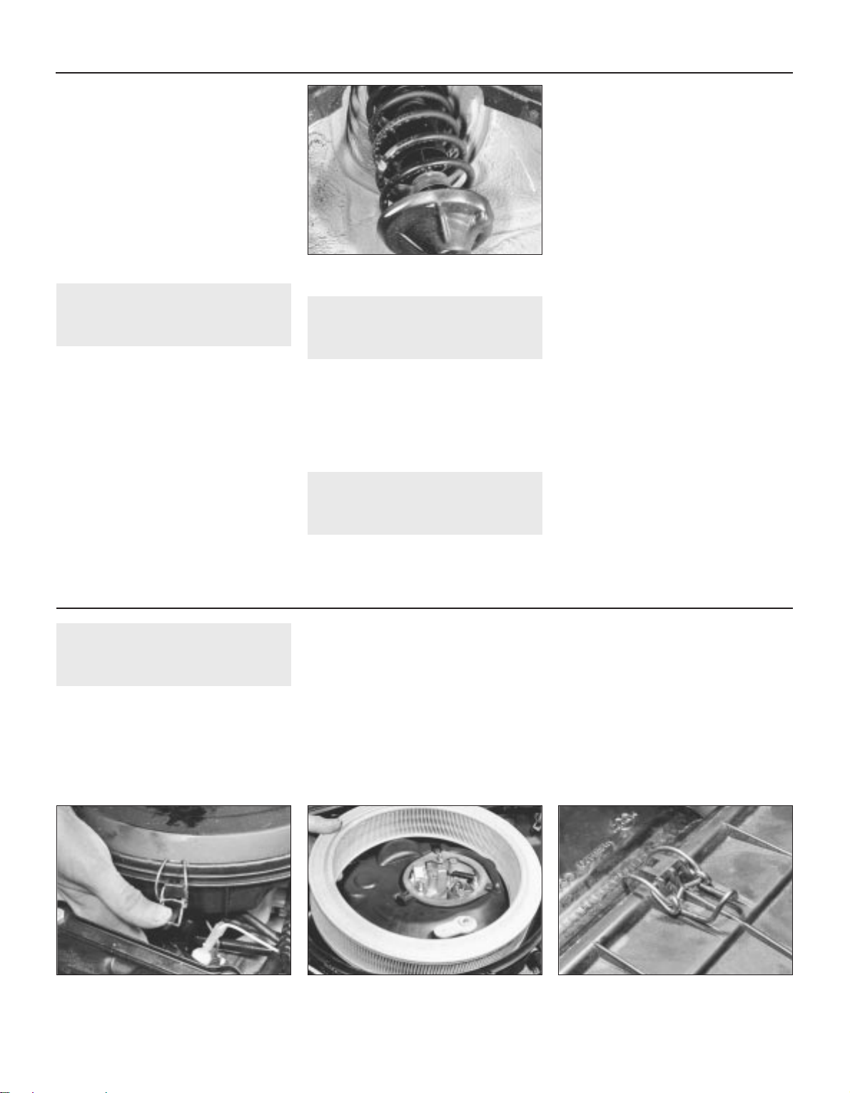
gripping the track rod. If the wheel is now
rocked, movement will be felt at the inner joint
if wear has taken place.
4 With the vehicle standing on its wheels,
have an assistant turn the steering wheel back
and forth about an eighth of a turn each way.
There should be very little, if any, lost
movement between the steering wheel and
the roadwheels. If this is not the case, closely
observe the joints and mountings previously
described, but in addition check for wear of
the steering column universal joint and the
steering gear itself.
29 Suspension check
1
1 Raise and support each end of the vehicle
in turn and inspect the suspension
components for signs of excessive wear or
damage as follows.
2 Inspect the suspension balljoints for wear
and the dust covers for any signs of splits or
deterioration. Renew if necessary.
3 Check the track control arm (wishbone) and
anti-roll bar mounting/pivot bushes for signs
of excessive wear and/or deterioration and
again renew if necessary.
4 Check the shock absorbers for signs of
leakage and the suspension to subframe and
body mountings for signs of corrosion (see
illustration).
30 Hinge and catch lubrication
1
1 Lubricate the door, bonnet and tailgate
hinges with a little light machine oil.
2 Lubricate also the bonnet release
mechanism and door, bonnet and tailgate
locks. Do not lubricate the steering lock.
3 At the same time lubricate the door check
straps with a little multi-purpose grease.
31 Vehicle underbody check
1
Note: Steam-cleaning is available at many
garages for the purpose of removing any
accumulation of oily grime from beneath a
vehicle.
1 Raise the vehicle sufficiently enough to
allow a complete uninterrupted view of its
underside.
2 Wash the vehicle underbody down as
thoroughly as possible.
3 Carefully check all underbody paintwork,
looking closely for chips or scratches. Check
with particular care vulnerable areas such as
the front spoiler and around the wheel arches.
Any damage to the paintwork must be
rectified to prevent further corrosion.
4 If a chip or light scratch is found that is
recent and still free from rust, it can be
touched-up using the appropriate paint. More
serious damage or rusted stone chips can be
repaired as described in Chapter 11. If
damage or corrosion is so severe that a panel
must be renewed, seek professional advice as
soon as possible.
5 The wax-based underbody protective
coating should now be inspected to ensure
that it is unbroken and any damage to the
coating repaired using undershield. If any
body panels are disturbed for repair or
renewed, do not forget to replace the coating
and to inject wax into door panels, sills, box
sections etc. so as to maintain the level of
protection provided by the manufacturer.
6 Check carefully that all wheel arch liners
and underwing shields are in place and
securely fastened.
7 Finally, check that all door and ventilator
opening drain holes and pipes are completely
clear so that water is allowed to drain.
32 Air cleaner element renewal
1
Carburettor models
1.05 and 1.3 litre engines
1 Release the spring clips securing the air
cleaner lid and remove the lid (see
illustration).
2 Cover the carburettor entry port to prevent
any dirt entering it when the element is lifted
out. Remove the element (see illustration).
Wipe the inside of the air cleaner with a moist
rag to remove all dust and dirt and then
remove the covering from the entry port.
3 Fit the new element. Clean the cover,
position it in place, then clip it down whilst
ensuring that the two arrows are aligned.
1.6 and 1.8 litre engines
4 Unclip and remove the cover then withdraw
the element. Note that on some models, it is
necessary to first loosen the front mounting
nut (see illustrations).
5 Clean the interior of the air cleaner with a
fuel-moistened cloth, then wipe it dry.
6 Fit the new element in the reverse order of
removal.
Fuel-injected models
7 Release the spring clips securing the air
cleaner cover and separate the cover from the
airflow meter (see illustration).
1•20 Every 10 000 miles or 12 months
29.4 Check shock absorbers for leakage
32.1 Unclip the air cleaner lid . . . 32.2 . . . and remove the element -
1.3 litre, carburettor
32.4a Unclip air cleaner cover . . .
1081 VW Golf & Jetta
Every 20 000 miles (30 000 km) or 24 months
Page 39
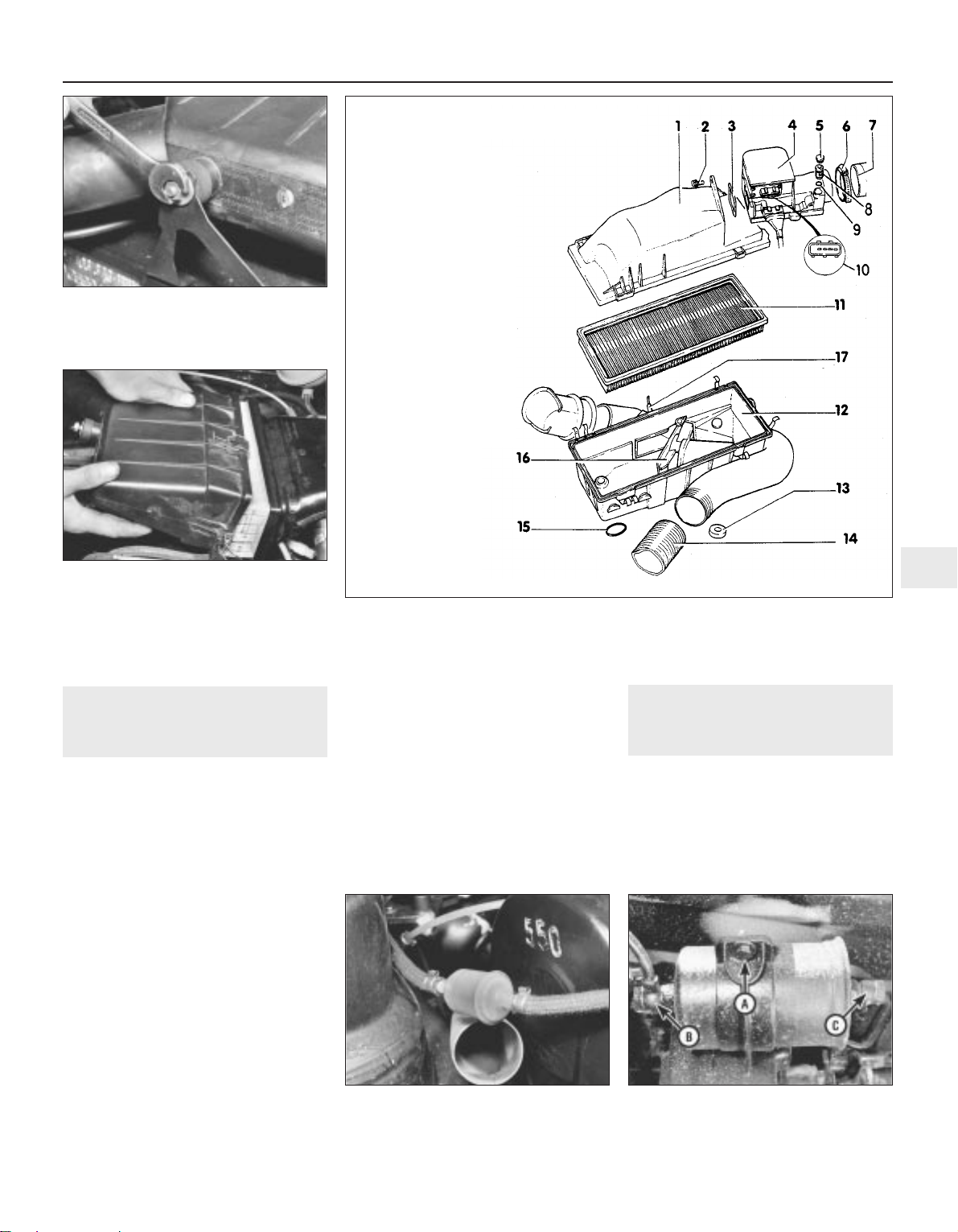
8 Withdraw the element from the housing.
9 Wipe clean the inside of the cover.
10 Fit the new element and secure the cover
by pressing the clips home.
33 Fuel filter renewal
2
Carburettor models
1 To remove the in-line filter, remove its pipe
retaining clips, disconnect the pipes and
extract the filter (see illustration). If
necessary, replace the original crimped type
clips with screw type ones.
2 Fit the new filter in a horizontal position with
its arrow facing the flow of fuel towards the
fuel pump. Ensure that the pipe retaining clips
are properly tightened then start the engine
and check carefully for any signs of fuel leaks
from the pipe ends.
3 Dispose safely of the old filter, it will be
highly inflammable and may explode if thrown
on a fire.
Fuel-injected models
4 The fuel filter is mounted on the inboard
side of the pump reservoir on the underside of
the vehicle at the rear just forward of the fuel
tank (see illustration)
5 Disconnect the battery earth lead.
6 Raise the vehicle at the rear and support it
on axle stands (see “Jacking and vehicle
support”).
7 At the forward end of the filter, undo the
fuel accumulator hose union bolt and detach
the union whilst collecting the washer each
side of it.
8 At the rear end of the filter, detach the fuel
supply hose (to the metering distributor) by
undoing the union bolt. Collect the washer
each side of the union.
9 Loosen the filter retaining clamp and
withdraw the filter.
10 Fitting the new filter is a reversal of the
removal procedure. Renew the union washers
and tighten the union bolts to the specified
torque. Check that the arrow on the filter
points in the direction of fuel flow.
11 On completion, check for any signs of fuel
leakage with the engine running.
12 Dispose safely of the old filter, it will be
highly inflammable and may explode if thrown
on a fire.
34 Sunroof guide rail cleaning
and lubrication
1
Open the sunroof and wipe clean its guide
rails. Coat each rail very lightly with grease,
ensuring that none finds its way onto the
interior trim.
Check that the sunroof opens and closes
smoothly throughout its complete operating
range.
Every 20 000 miles or 24 months 1•21
1
32.4b . . . loosen front mounting nut . . .
32.4c . . . then remove cover to expose
element - 1.6 and 1.8 litre, carburettor
33.4 Fuel filter unit clamp (A) hose to
accumulator (B) and hose to metering
valve (C) - K-Jetronic fuel injection
33.1 In-line fuel filter - 1.05 and 1.3 litre,
carburettor
1081 VW Golf & Jetta
32.7 Air cleaner components Digijet fuel injection
1 Upper cover
2 Screws
3 O-ring
4 Airflow meter
5 Tamperproof plug
6 Hose clip
7 Intake hose
8 Mixture (CO content)
adjusting screw
9 O-ring
10 Connector
11 Air cleaner element
12 Lower body
13 Rubber washer
14 Pre-heater hose
15 Retaining ring
16 Air intake pre-heater
regulator flap
17 To inlet elbow
Page 40
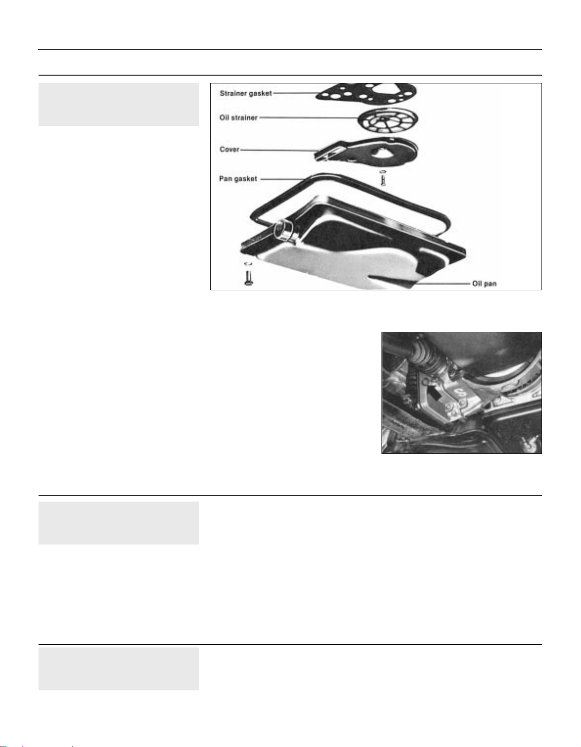
37 Timing belt renewal
3
Refer to the appropriate Part of Chapter 2
for the particular engine type concerned.
36 Brake fluid renewal
3
1 The procedure is similar to that described
for bleeding of the hydraulic system in
Chapter 9, except that the brake fluid
reservoir should be emptied before starting by
syphoning, using a clean poultry baster or
similar. Also, allowance should be made for
the old fluid to be expelled when bleeding a
section of the circuit.
2 Working as described in Chapter 9, open
the first bleed nipple in the sequence and
pump the brake pedal gently until nearly all
the old fluid has been emptied from the
master cylinder reservoir. Top-up to the MAX
level with new fluid and continue pumping
until only the new fluid remains in the reservoir
and new fluid can be seen emerging from the
bleed nipple. Tighten the nipple and top the
reservoir level up to the MAX level line.
3 Old hydraulic fluid is invariably much darker
in colour than the new, making it easy to
distinguish the two.
4 Work through all the remaining nipples in
the sequence until new fluid can be seen at all
of them. Be careful to keep the master
cylinder reservoir topped up to above the MIN
level at all times or air may enter the system
and greatly increase the length of the task.
5 When the operation is complete, check that
all nipples are securely tightened and that
their dust caps are refitted. Wash off all traces
of spilt fluid and recheck the master cylinder
reservoir fluid level.
6 Check the operation of the brakes before
taking the vehicle on the road.
35 Automatic transmission and
final drive fluid renewal
2
Note: Under extreme operating conditions,
automatic transmission fluid should be
changed at more frequent intervals.
Automatic transmission
1 Whenever the automatic transmission fluid
is renewed, the oil pan and strainer must also
be cleaned (where applicable). First jack up
the vehicle and support it on axle stands (see
“Jacking and vehicle support”).
2 Remove the transmission drain plug and drain
the fluid into a container. If there is no drain plug,
loosen the oil pan front bolts then unscrew the
rear bolts and lower the pan in order to drain the
fluid (see illustration). Take care to avoid
scalding if the engine has just been run.
3 Unbolt and remove the pan from the
transmission and remove the gasket. Clean
the inside of the pan.
4 Unbolt the strainer cover and remove the
strainer and gasket.
5 Clean the strainer and cover and dry
thoroughly.
6 Refit the cover and strainer, together with a
new gasket, and tighten the bolts to the
specified torque.
7 Refit the pan, together with a new gasket,
and tighten the securing bolts to the specified
torque. Lower the vehicle.
8 Initially, refill the transmission with 2.5 litres
of the specified fluid, then restart the engine.
Check that the handbrake is fully applied then
move the gear selector lever through the full
range of gears finishing at N. With the engine
still idling, check the fluid level on the dipstick.
The fluid level should at least be visible on the
dipstick. If not, add the minimum amount of
fluid necessary to bring the level up to be
visible on the tip of the dipstick.
9 Take the vehicle on a short drive to
warm-up the fluid in the transmission then
recheck the fluid level. Top-up if necessary.
Do not overfill with fluid or the excess will
have to be drained off.
Final drive unit
10 To check the oil level in the final drive unit,
the vehicle will need to be over an inspection
pit or raised and supported on a level position
on axle stands (see “Jacking and vehicle
support”) for access to the filler/level plug
(see illustration).
11 Remove the plug and check that the oil is
level with the bottom edge of the plug hole. If
not, top-up the level through the plug hole
then refit the plug. Lower the vehicle.
1•22 Maintenance procedures
35.10 Final drive unit oil filler/level plug
(arrowed)
1081 VW Golf & Jetta
Every 30 000 miles (45 000 km)
Every 2 years
Every 40 000 miles (60 000 km)
35.2 Automatic transmission oil pan and strainer
Page 41

1081 VW Golf & Jeta
2A
Chapter 2 Part A:
Engine repair procedures -
1.05 and 1.3 litre pre August 1985
General
Type . . . . . . . . . . . . . . . . . . . . . . . . . . . . . . . . . . . . . . . . . . . . . . . . . . . . Four-cylinder in-line, water cooled, overhead camshaft
Code:
1.05 litre . . . . . . . . . . . . . . . . . . . . . . . . . . . . . . . . . . . . . . . . . . . . . . . GN
1.3 litre . . . . . . . . . . . . . . . . . . . . . . . . . . . . . . . . . . . . . . . . . . . . . . . . HK
Firing order . . . . . . . . . . . . . . . . . . . . . . . . . . . . . . . . . . . . . . . . . . . . . . . 1-3-4-2 (No 1 at camshaft sprocket end)
Displacement:
1.05 litre . . . . . . . . . . . . . . . . . . . . . . . . . . . . . . . . . . . . . . . . . . . . . . . 1043 cc
1.3 litre . . . . . . . . . . . . . . . . . . . . . . . . . . . . . . . . . . . . . . . . . . . . . . . . 1272 cc
Bore:
1.05 litre . . . . . . . . . . . . . . . . . . . . . . . . . . . . . . . . . . . . . . . . . . . . . . . 75.0 mm
1.3 litre . . . . . . . . . . . . . . . . . . . . . . . . . . . . . . . . . . . . . . . . . . . . . . . . 75.0 mm
Stroke:
1.05 litre . . . . . . . . . . . . . . . . . . . . . . . . . . . . . . . . . . . . . . . . . . . . . . . 59.0 mm
1.3 litre . . . . . . . . . . . . . . . . . . . . . . . . . . . . . . . . . . . . . . . . . . . . . . . . 72.0 mm
Compression ratio:
1.05 litre . . . . . . . . . . . . . . . . . . . . . . . . . . . . . . . . . . . . . . . . . . . . . . . 9.5 to 1
1.3 litre . . . . . . . . . . . . . . . . . . . . . . . . . . . . . . . . . . . . . . . . . . . . . . . . 9.5 to 1
Compression pressure:
New . . . . . . . . . . . . . . . . . . . . . . . . . . . . . . . . . . . . . . . . . . . . . . . . . . . 8 to 10 bar
Minimum . . . . . . . . . . . . . . . . . . . . . . . . . . . . . . . . . . . . . . . . . . . . . . . 7.0 bar
Maximum permissible difference between any two cylinders . . . . . . 3.0 bar
Camshaft - examination and renovation . . . . . . . . . . . . . . . . . . . . . . 27
Camshaft - refitting . . . . . . . . . . . . . . . . . . . . . . . . . . . . . . . . . . . . . . 35
Camshaft - removal . . . . . . . . . . . . . . . . . . . . . . . . . . . . . . . . . . . . . . 10
Crankshaft and bearings - examination and renovation . . . . . . . . . . 21
Crankshaft and main bearings - refitting . . . . . . . . . . . . . . . . . . . . . . 29
Crankshaft and main bearings - removal . . . . . . . . . . . . . . . . . . . . .18
Crankshaft oil seals - renewal . . . . . . . . . . . . . . . . . . . . . . . . . . . . . . 14
Cylinder block/crankcase - examination and renovation . . . . . . . . . 22
Cylinder head - dismantling and overhaul . . . . . . . . . . . . . . . . . . . . . 11
Cylinder head - reassembly . . . . . . . . . . . . . . . . . . . . . . . . . . . . . . . . 34
Cylinder head - refitting . . . . . . . . . . . . . . . . . . . . . . . . . . . . . . . . . . . 36
Cylinder head - removal . . . . . . . . . . . . . . . . . . . . . . . . . . . . . . . . . . 9
Engine dismantling - general information . . . . . . . . . . . . . . . . . . . . . 7
Engine reassembly - general information . . . . . . . . . . . . . . . . . . . . . 28
Engine - adjustments after major overhaul . . . . . . . . . . . . . . . . . . . . 41
Engine ancillary components - removal . . . . . . . . . . . . . . . . . . . . . . 8
Engine ancillary components and gearbox - refitting . . . . . . . . . . . . 39
Engine - refitting . . . . . . . . . . . . . . . . . . . . . . . . . . . . . . . . . . . . . . . . 40
Engine - removal . . . . . . . . . . . . . . . . . . . . . . . . . . . . . . . . . . . . . . . . 5
Engine/gearbox - separation . . . . . . . . . . . . . . . . . . . . . . . . . . . . . . . 6
Examination and renovation - general information . . . . . . . . . . . . . . 20
Flywheel - examination and renovation . . . . . . . . . . . . . . . . . . . . . . . 25
Flywheel - refitting . . . . . . . . . . . . . . . . . . . . . . . . . . . . . . . . . . . . . . . 33
Flywheel - removal . . . . . . . . . . . . . . . . . . . . . . . . . . . . . . . . . . . . . . . 13
General information . . . . . . . . . . . . . . . . . . . . . . . . . . . . . . . . . . . . . . 1
Major operation only possible after removal of engine from vehicle . . 3
Major operations possible with engine in vehicle . . . . . . . . . . . . . . . 2
Method of engine removal . . . . . . . . . . . . . . . . . . . . . . . . . . . . . . . . . 4
Oil filter - renewal . . . . . . . . . . . . . . . . . . . . . . . . . . . . . . . . . . . . . . . . 19
Oil pump - examination and renovation . . . . . . . . . . . . . . . . . . . . . . 24
Oil pump - refitting . . . . . . . . . . . . . . . . . . . . . . . . . . . . . . . . . . . . . . . 31
Oil pump - removal . . . . . . . . . . . . . . . . . . . . . . . . . . . . . . . . . . . . . . 16
Pistons and connecting rods - examination and renovation . . . . . . . 23
Pistons and connecting rods - refitting . . . . . . . . . . . . . . . . . . . . . . . 30
Pistons and connecting rods - removal . . . . . . . . . . . . . . . . . . . . . . . 17
Sump - refitting . . . . . . . . . . . . . . . . . . . . . . . . . . . . . . . . . . . . . . . . . 32
Sump - removal . . . . . . . . . . . . . . . . . . . . . . . . . . . . . . . . . . . . . . . . ..15
Timing belt and sprockets - examination and renovation . . . . . . . . . 26
Timing belt and sprockets - refitting . . . . . . . . . . . . . . . . . . . . . . . . . 37
Timing belt and sprockets - removal . . . . . . . . . . . . . . . . . . . . . . . . . 12
Valve clearances - checking and adjustment . . . . . . . . . . . . . . . . . . 38
2A•1
Specifications
Contents
Easy, suitable for
novice with little
experience
Fairly easy, suitable
for beginner with
some experience
Fairly difficult,
suitable for competent
DIY mechanic
Difficult, suitable for
experienced DIY
mechanic
Very difficult,
suitable for expert DIY
or professional
Degrees of difficulty
5
4
3
2
1
Page 42

Crankshaft
Main journal:
Standard diameter . . . . . . . . . . . . . . . . . . . . . . . . . . . . . . . . . . . . . . . 54.0 mm
Undersizes . . . . . . . . . . . . . . . . . . . . . . . . . . . . . . . . . . . . . . . . . . . . . 53.75, 53.50 and 53.25 mm
Crankpin:
Standard diameter . . . . . . . . . . . . . . . . . . . . . . . . . . . . . . . . . . . . . . . 42 mm
Journal undersizes . . . . . . . . . . . . . . . . . . . . . . . . . . . . . . . . . . . . . . . 41.75, 41.50 and 41.25 mm
Endfloat:
Maximum . . . . . . . . . . . . . . . . . . . . . . . . . . . . . . . . . . . . . . . . . . . . . . 0.20 mm
Minimum . . . . . . . . . . . . . . . . . . . . . . . . . . . . . . . . . . . . . . . . . . . . . . . 0.07 mm
Main bearing maximum running clearance . . . . . . . . . . . . . . . . . . . . . . 0.17 mm
Connecting rods
Big-end:
Maximum running clearance . . . . . . . . . . . . . . . . . . . . . . . . . . . . . . . . 0.095 mm
Maximum endfloat . . . . . . . . . . . . . . . . . . . . . . . . . . . . . . . . . . . . . . . 0.40 mm
Pistons
Clearance in bore:
Maximum . . . . . . . . . . . . . . . . . . . . . . . . . . . . . . . . . . . . . . . . . . . . . . 0.07 mm
Minimum . . . . . . . . . . . . . . . . . . . . . . . . . . . . . . . . . . . . . . . . . . . . . . . 0.03 mm
Diameter:
Standard . . . . . . . . . . . . . . . . . . . . . . . . . . . . . . . . . . . . . . . . . . . . . . . 74.98 mm
Oversize:
1st oversize . . . . . . . . . . . . . . . . . . . . . . . . . . . . . . . . . . . . . . . . . . . 75.23 mm
2nd oversize . . . . . . . . . . . . . . . . . . . . . . . . . . . . . . . . . . . . . . . . . . 75.48 mm
3rd oversize . . . . . . . . . . . . . . . . . . . . . . . . . . . . . . . . . . . . . . . . . . . 75.98 mm
Wear limit (10 mm from base/ right angles to pin) . . . . . . . . . . . . . . . . . 0.04 mm
Piston rings
Maximum clearance in groove. . . . . . . . . . . . . . . . . . . . . . . . . . . . . . . . 0.15 mm
End gap:
Compression rings . . . . . . . . . . . . . . . . . . . . . . . . . . . . . . . . . . . . . . . 0.30 to 0.45 mm
Oil scraper ring . . . . . . . . . . . . . . . . . . . . . . . . . . . . . . . . . . . . . . . . . . 0.25 to 0.40 mm
Gudgeon pin
Fit in piston . . . . . . . . . . . . . . . . . . . . . . . . . . . . . . . . . . . . . . . . . . . . . . . Push fit at 60°C
Cylinder head
Maximum allowable face distortion . . . . . . . . . . . . . . . . . . . . . . . . . . . . 0.1 mm
Camshaft
Run-out at centre bearing . . . . . . . . . . . . . . . . . . . . . . . . . . . . . . . . . . . . 0.02 mm
Endfloat . . . . . . . . . . . . . . . . . . . . . . . . . . . . . . . . . . . . . . . . . . . . . . . . . . 0.15 mm
Valves
Seat angle . . . . . . . . . . . . . . . . . . . . . . . . . . . . . . . . . . . . . . . . . . . . . . . . 45°
Head diameter:
Inlet . . . . . . . . . . . . . . . . . . . . . . . . . . . . . . . . . . . . . . . . . . . . . . . . . . . 34.0 mm
Exhaust . . . . . . . . . . . . . . . . . . . . . . . . . . . . . . . . . . . . . . . . . . . . . . . . 28.1 mm
Stem diameter:
Inlet . . . . . . . . . . . . . . . . . . . . . . . . . . . . . . . . . . . . . . . . . . . . . . . . . . . 7.97 mm
Exhaust . . . . . . . . . . . . . . . . . . . . . . . . . . . . . . . . . . . . . . . . . . . . . . . . 7.95 mm
Standard overall length:
Inlet . . . . . . . . . . . . . . . . . . . . . . . . . . . . . . . . . . . . . . . . . . . . . . . . . . . 110.5 mm
Exhaust . . . . . . . . . . . . . . . . . . . . . . . . . . . . . . . . . . . . . . . . . . . . . . . . 110.5 mm
Valve guides
Maximum valve rock (stem flush with guide):
Inlet . . . . . . . . . . . . . . . . . . . . . . . . . . . . . . . . . . . . . . . . . . . . . . . . . . . 1.0 mm
Exhaust . . . . . . . . . . . . . . . . . . . . . . . . . . . . . . . . . . . . . . . . . . . . . . . . 1.3 mm
Valve timing
Nil valve clearance at 1.0 mm valve lift
1.05 litre:
Inlet opens . . . . . . . . . . . . . . . . . . . . . . . . . . . . . . . . . . . . . . . . . . . . . 9° ATDC
Inlet closes . . . . . . . . . . . . . . . . . . . . . . . . . . . . . . . . . . . . . . . . . . . . . 13° ABDC
Exhaust opens . . . . . . . . . . . . . . . . . . . . . . . . . . . . . . . . . . . . . . . . . . 15° BBDC
Exhaust closes . . . . . . . . . . . . . . . . . . . . . . . . . . . . . . . . . . . . . . . . . . 11° BTDC
2A•2 Engine repair procedures - 1.05 and 1.3 litre pre August 1985
1081 VW Golf & Jeta
Page 43

1.3 litre:
Inlet opens . . . . . . . . . . . . . . . . . . . . . . . . . . . . . . . . . . . . . . . . . . . . . 3° BTDC
Inlet closes . . . . . . . . . . . . . . . . . . . . . . . . . . . . . . . . . . . . . . . . . . . . . 38° ABDC
Exhaust opens . . . . . . . . . . . . . . . . . . . . . . . . . . . . . . . . . . . . . . . . . . 41° BBDC
Exhaust closes . . . . . . . . . . . . . . . . . . . . . . . . . . . . . . . . . . . . . . . . . . 3° BTDC
Valve clearances
Warm:
Inlet . . . . . . . . . . . . . . . . . . . . . . . . . . . . . . . . . . . . . . . . . . . . . . . . . . . 0.15 to 0.20 mm
Exhaust . . . . . . . . . . . . . . . . . . . . . . . . . . . . . . . . . . . . . . . . . . . . . . . . 0.25 to 0.30 mm
Cold:
Inlet . . . . . . . . . . . . . . . . . . . . . . . . . . . . . . . . . . . . . . . . . . . . . . . . . . . 0.10 to 0.15 mm
Exhaust . . . . . . . . . . . . . . . . . . . . . . . . . . . . . . . . . . . . . . . . . . . . . . . . 0.20 to 0.25 mm
Lubrication
System type . . . . . . . . . . . . . . . . . . . . . . . . . . . . . . . . . . . . . . . . . . . . . . Wet sump, pressure feed, full flow filter
Lubricant type/specification/capacity . . . . . . . . . . . . . . . . . . . . . . . . . . Refer to
“Lubricants, fluids and capacities”
Filter type . . . . . . . . . . . . . . . . . . . . . . . . . . . . . . . . . . . . . . . . . . . . . . . . Champion C101/C160
Pump type . . . . . . . . . . . . . . . . . . . . . . . . . . . . . . . . . . . . . . . . . . . . . . . Eccentric gear driven by crankshaft
Pressure (2000 rpm with oil temperature 80°C) . . . . . . . . . . . . . . . . . . . 2.0 bar minimum
Torque wrench settings Nm lbf ft
Engine to gearbox . . . . . . . . . . . . . . . . . . . . . . . . . . . . . . . . . . . . . . . . . 55 41
Exhaust pipe to manifold . . . . . . . . . . . . . . . . . . . . . . . . . . . . . . . . . . . . 25 18
Flywheel bolts . . . . . . . . . . . . . . . . . . . . . . . . . . . . . . . . . . . . . . . . . . . . . 75 55
Clutch bolts . . . . . . . . . . . . . . . . . . . . . . . . . . . . . . . . . . . . . . . . . . . . . . 25 18
Sump bolts . . . . . . . . . . . . . . . . . . . . . . . . . . . . . . . . . . . . . . . . . . . . . . . 20 15
Sump drain plug . . . . . . . . . . . . . . . . . . . . . . . . . . . . . . . . . . . . . . . . . . . 30 22
Main bearing cap bolts . . . . . . . . . . . . . . . . . . . . . . . . . . . . . . . . . . . . . . 65 48
Oil pump bolts . . . . . . . . . . . . . . . . . . . . . . . . . . . . . . . . . . . . . . . . . . . . 10 7
Connecting rod big-end cap nuts (oiled):
Stage 1 . . . . . . . . . . . . . . . . . . . . . . . . . . . . . . . . . . . . . . . . . . . . . . . . 30 22
Stage 2* . . . . . . . . . . . . . . . . . . . . . . . . . . . . . . . . . . . . . . . . . . . . . . . Tighten further 1/4 turn (90°)
Oil suction pipe to pump . . . . . . . . . . . . . . . . . . . . . . . . . . . . . . . . . . . . 10 7
Oil relief valve plug . . . . . . . . . . . . . . . . . . . . . . . . . . . . . . . . . . . . . . . . . 25 18
Oil pressure sender switch . . . . . . . . . . . . . . . . . . . . . . . . . . . . . . . . . . . 25 18
Timing cover . . . . . . . . . . . . . . . . . . . . . . . . . . . . . . . . . . . . . . . . . . . . . . 10 7
Valve cover . . . . . . . . . . . . . . . . . . . . . . . . . . . . . . . . . . . . . . . . . . . . . . . 10 7
Camshaft sprocket bolt . . . . . . . . . . . . . . . . . . . . . . . . . . . . . . . . . . . . . 80 59
Crankshaft sprocket/pulley nut . . . . . . . . . . . . . . . . . . . . . . . . . . . . . . . 80 59
Coolant pump bolts . . . . . . . . . . . . . . . . . . . . . . . . . . . . . . . . . . . . . . . . 10 7
Distributor flange bolts . . . . . . . . . . . . . . . . . . . . . . . . . . . . . . . . . . . . . . 20 15
Cylinder head bolts (engine cold):
Stage 1 . . . . . . . . . . . . . . . . . . . . . . . . . . . . . . . . . . . . . . . . . . . . . . . . 40 30
Stage 2 . . . . . . . . . . . . . . . . . . . . . . . . . . . . . . . . . . . . . . . . . . . . . . . . 60 44
Stage 3 . . . . . . . . . . . . . . . . . . . . . . . . . . . . . . . . . . . . . . . . . . . . . . . . Tighten further 1/2 turn (180°)
Engine mountings (with oiled threads):
Refer to illustrations 40.1a and 40.1b
(a) M8 . . . . . . . . . . . . . . . . . . . . . . . . . . . . . . . . . . . . . . . . . . . . . . . . . 25 18
(a) M10 . . . . . . . . . . . . . . . . . . . . . . . . . . . . . . . . . . . . . . . . . . . . . . . . 45 33
(b) . . . . . . . . . . . . . . . . . . . . . . . . . . . . . . . . . . . . . . . . . . . . . . . . . . . . 35 26
(c) . . . . . . . . . . . . . . . . . . . . . . . . . . . . . . . . . . . . . . . . . . . . . . . . . . . . 45 33
(d) . . . . . . . . . . . . . . . . . . . . . . . . . . . . . . . . . . . . . . . . . . . . . . . . . . . . 50 37
(e) . . . . . . . . . . . . . . . . . . . . . . . . . . . . . . . . . . . . . . . . . . . . . . . . . . . . 60 44
(f) . . . . . . . . . . . . . . . . . . . . . . . . . . . . . . . . . . . . . . . . . . . . . . . . . . . . 70 52
(g) . . . . . . . . . . . . . . . . . . . . . . . . . . . . . . . . . . . . . . . . . . . . . . . . . . . . 80 59
* When checking the connecting rod-to-crankshaft journal radial clearance using Plastigage, tighten only to 30Nm (22 lbf ft).
Engine repair procedures - 1.05 and 1.3 litre pre August 1985 2A•3
2A
1081 VW Golf & Jeta
1 General information
The 1.05 and 1.3 litre engines are of
four-cylinder, in-line, overhead camshaft type,
mounted transversely at the front of the
vehicle. The transmission is attached to the
left-hand side of the engine.
The crankshaft is of five bearing type and
separate thrustwashers are fitted to the
central main bearing to control crankshaft
endfloat.
The camshaft is driven by a toothed belt
which also drives the coolant pump. The
toothed belt is tensioned by moving the coolant
pump in its eccentric mounting. The valves are
operated from the camshaft by rocker fingers
which pivot on ball-head studs. The distributor
is driven by the camshaft and is located on the
left-hand end of the cylinder head.
The oil pump is of the eccentric gear type
driven from the end of the crankshaft.
The cylinder head is of crossflow design,
with the inlet manifold at the rear and the
exhaust manifold at the front.
The crankcase ventilation system is of the
positive type and consists of an oil separator
on the rear (coolant pipe side) of the cylinder
Page 44
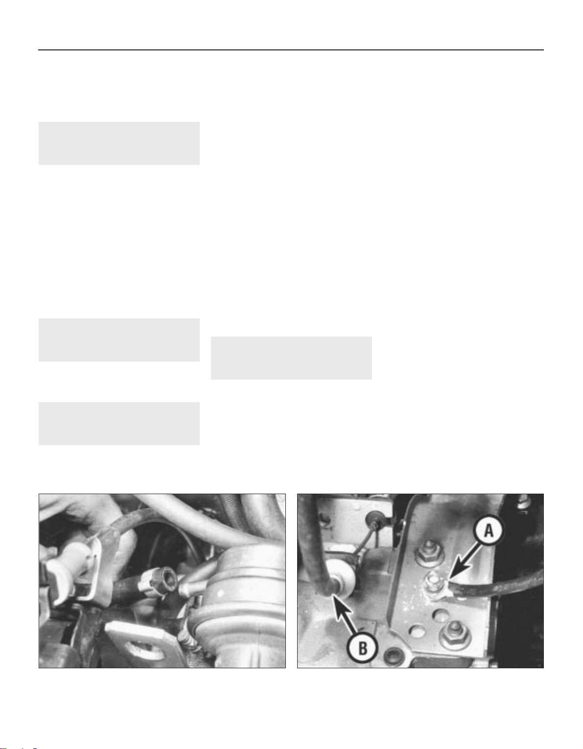
block, connected to the air cleaner by a
rubber hose. Vacuum from the air cleaner
provides a partial vacuum in the crankcase
and the piston blow-by gases are drawn
through the oil separator and into the engine
combustion chambers.
2 Major operations possible
with engine in vehicle
The following operations can be carried out
without having to remove the engine from the
vehicle:
a) Removal and servicing of the cylinder
head, camshaft and timing belt
b) Removal of the flywheel and crankshaft
rear oil seal (after removal of the gearbox)
c) Removal of the sump
d) Removal of the piston/connecting rod
assemblies (after removal of the cylinder
head and sump)
e) Renewal of the crankshaft front and rear
oil seals and the camshaft front oil seal
f) Renewal of the engine mountings
g) Removal of the oil pump
3 Major operation only
possible after removal of
engine from vehicle
The following operation can only be carried
out after removal of the engine from the vehicle:
a) Renewal of crankshaft main bearings
4 Method of engine removal
1 The engine, together with the gearbox,
must be lifted from the engine compartment
and the engine separated from the gearbox
on the bench. Two people will be needed.
2 A hoist of 150 kg capacity will be needed to
lift the engine approximately 1 metre. If the
hoist is not portable, then sufficient room
must be left behind the vehicle to push it back
out of the way so that the engine may be
lowered. Blocks will be needed to support the
engine after removal.
3 Ideally the vehicle should be over a pit. If
this is not possible then the body must be
supported on axle stands (see “Jacking and
vehicle support”) so that the front wheels may
be turned to undo the driveshaft nuts. The
left-hand shaft is accessible from above but
the right-hand shaft must be undone from
underneath. Removal of the gearshift linkage
can only be done from underneath, as can
removal of the exhaust pipe bracket. When all
tasks are complete, lower the vehicle back
onto its wheels.
4 A set of splined keys will be required to
remove and refit the socket-head bolts used
to secure certain items, such as the cylinder
head bolts.
5 Draining of oil and coolant is best done
away from the working area if possible. This
saves the mess made by spilled oil in the
place where you must work.
6 If an air conditioning system is fitted,
observe the precautions listed in Chapter 3.
5 Engine - removal
4
1 Disconnect the battery negative lead.
2 Remove the bonnet.
3 Drain the engine coolant and remove the
radiator, complete with cooling fan unit.
4 Remove the air cleaner unit.
5 Loosen the clip and disconnect the top
hose from the thermostat housing.
6 Place a container beneath the engine then
unscrew the sump drain plug and drain the oil
- see Chapter 1. When complete, clean the
drain plug and washer and refit it to the sump.
7 Identify the fuel supply and return hoses
then disconnect them from the fuel pump (see
illustration) and fuel reservoir/carburettor.
Plug the hoses to prevent fuel leakage.
8 Loosen the clip and disconnect the bottom
hose from the coolant pipe at the rear of the
engine.
9 Disconnect the accelerator cable and,
where applicable, the choke cable.
10 Disconnect the heater hoses from the
thermostat housing and rear coolant pipe.
11 Detach the following connections,
identifying each lead as it is disconnected to
avoid confusion on reassembly:
a) The oil pressure switches on the rear
(carburettor side) of the cylinder head
b) Inlet manifold preheating element line
connector
c) Thermo-switch leads (coolant hose
intermediate piece)
d) Distributor HT and LT leads
e) Starter motor
f) Temperature sender unit (thermostat
housing)
g) Fuel cut-off solenoid valve on carburettor
h) Earth strap to gearbox
12 Detach the wiring loom from the location
clip on the bottom hose and fold back out of
the way.
13 Disconnect and unclip the vacuum hoses
from the distributor and inlet manifold as
necessary.
14 Disconnect the clutch cable (see
illustration).
15 Disconnect the exhaust downpipe from
the exhaust manifold.
16 Disconnect the speedometer cable from
the gearbox and place it on one side.
17 Apply the handbrake then jack up the
front of the vehicle and support it on axle
stands (see “Jacking and vehicle support”).
18 Remove the screw from the shift rod
coupling and ease the coupling from the rod
(see illustration). The screw threads are
coated with a liquid locking agent and if
2A•4 Engine repair procedures - 1.05 and 1.3 litre pre August 1985
1081 VW Golf & Jeta
5.7 Detach hoses from fuel pump 5.14 Earth lead (A) and clutch cable (B)
Page 45
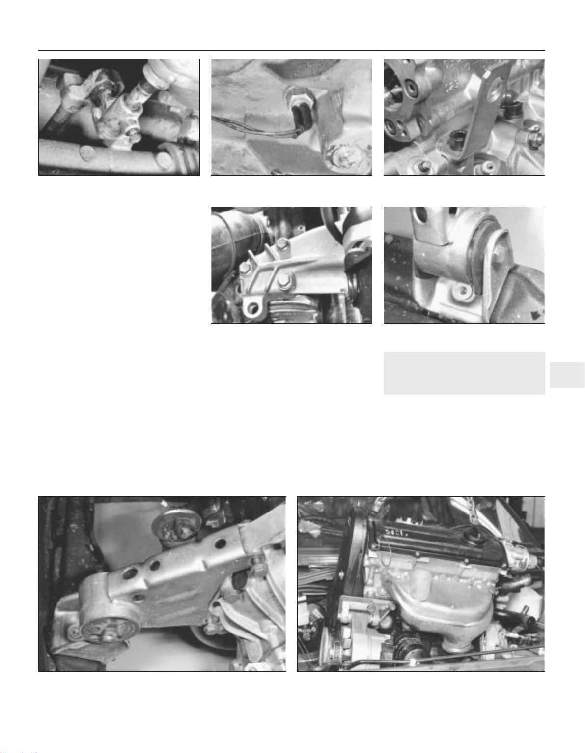
difficulty is experienced, it may be necessary
to heat up the coupling with a blowlamp whilst
observing the necessary fire precautions.
Note that once removed this screw should be
renewed.
19 Note its orientation then withdraw the shift
rod coupling.
20 Unbolt the exhaust steady bracket from
the downpipe and clutch housing/starter
motor.
21 Detach the reversing light switch lead
(see illustration).
22 Unbolt the driveshafts from the drive
flanges and tie them to one side with wire.
23 Attach a suitable hoist to the engine lifting
eye brackets (one at each end of the cylinder
head on the carburettor side) (see
illustration). Take the weight of the
engine/gearbox unit.
24 Working from above, undo the three
engine mounting/bearer retaining bolts
(underneath the carburettor) (see illustration).
25 Undo and remove the gearbox mounting
bolt (rear left side of engine compartment).
26 Undo and remove the front engine
mounting bolt and then remove the bolts
securing the bracket to the engine. Withdraw
the mounting (see illustrations).
27 Before lifting out the engine/gearbox unit,
get an assistant to hold the engine steady and
help guide it clear of surrounding components
as it is removed.
28 Lift the engine/gearbox unit from the
engine compartment (see illustration) while
turning it as necessary to clear the internally
mounted components. Make sure that all
wires, cables and hoses have been
disconnected.
29 Lower the unit onto a workbench or large
piece of wood placed on the floor.
6 Engine/gearbox - separation
3
1 The engine/gearbox unit must be
supported so that the gearbox can be eased
away from it. Either support the engine on
blocks so that the gearbox overhangs the
bench, or do the job while the engine and
gearbox are on the hoist.
2 Detach the lead from the alternator then
unclip the lead from the locating clips on the
sump side walls.
Engine repair procedures - 1.05 and 1.3 litre pre August 1985 2A•5
2A
5.18 Shift rod coupling screw 5.21 Reversing light switch 5.23 Engine lifting eye
5.24 Engine mounting/bearer - right-hand 5.26a Undo front mounting through-bolt
1081 VW Golf & Jeta
5.26b Unbolt and remove mounting unit 5.28 Lifting out engine/gearbox unit
Page 46
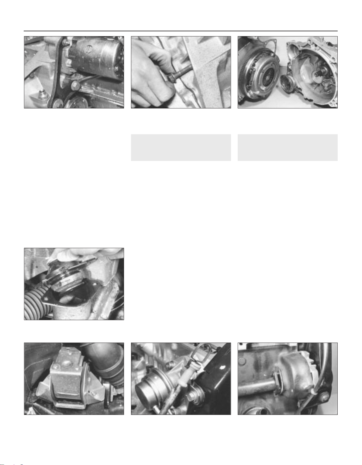
3 Because the rear bearing of the starter
armature is in the bellhousing, it is necessary
to remove the starter before separating the
engine and gearbox. If not already removed
when unbolting the starter motor, also detach
the exhaust pipe support bracket (see
illustration).
4 Detach the coolant pipe at its flange on the
rear side of the coolant pump and at the
clutch housing.
5 Undo the clutch housing belly plate bolt
and withdraw the plate.
6 Undo and remove the remaining
engine-to-gearbox securing bolts then pull the
gearbox free. Do not insert wedges or you will
damage the facing. Tap the gearbox gently
and wriggle it off the two dowels which locate
it. The intermediate plate will remain in
position (see illustrations).
7 Engine dismantling - general
information
1 If possible, mount the engine on a stand for
the dismantling procedure, but failing this,
support it in an upright position with blocks of
wood.
2 Cleanliness is most important. If the engine
is dirty, it should be cleaned with paraffin
while keeping it in an upright position.
3 Avoid working with the engine directly on a
concrete floor as grit presents a real source of
trouble.
4 As parts are removed, clean them in a
paraffin bath. Do not immerse parts with
internal oilways in paraffin as it is difficult to
remove. Clean oilways with nylon pipe
cleaners.
5 Obtain suitable containers to hold small
items. This will help when reassembling the
engine and also prevent possible loss.
6 Obtain complete sets of gaskets when the
engine is being dismantled but retain the old
gaskets with a view to using them as a pattern
to make a replacement if a new one is not
available.
7 When possible, refit nuts, bolts and
washers in their location after being removed.
This helps to protect the threads and will also
be helpful when reassembling the engine.
8 Retain unserviceable components in order
to compare them with the new parts supplied.
8 Engine ancillary components
- removal
3
With the engine removed from the vehicle
and separated from the gearbox, the
externally mounted ancillary components
should now be removed before dismantling
begins. The removal sequence need not
necessarily follow the order given:
a) Alternator and drivebelt
b) Inlet manifold and carburettor
c) Exhaust manifold
d) Distributor
e) Fuel pump
f) Thermostat
g) Clutch
h) Crankcase ventilation hose
i) Distributor cap and spark plugs
j) Oil filter
k) Engine mountings
(see illustrations)
l) Dipstick (see illustration)
m)Oil pressure switches
n) Coolant temperature thermo-switch
o) Alternator mounting bracket and engine
earth lead
p) Engine rear coolant pipe (see illustration)
2A•6 Engine repair procedures - 1.05 and 1.3 litre pre August 1985
6.3 Starter motor and exhaust support
bracket
6.6a Undo securing bolts (recessed bolt
shown) . . .
6.6b . . . then separate engine and
transmission
8.1b Right-hand rear mounting viewed
from above
8.1a Lift the mounting away
8.1c Engine dipstick and tube 8.1d Removing engine rear coolant pipe
1081 VW Golf & Jeta
Page 47
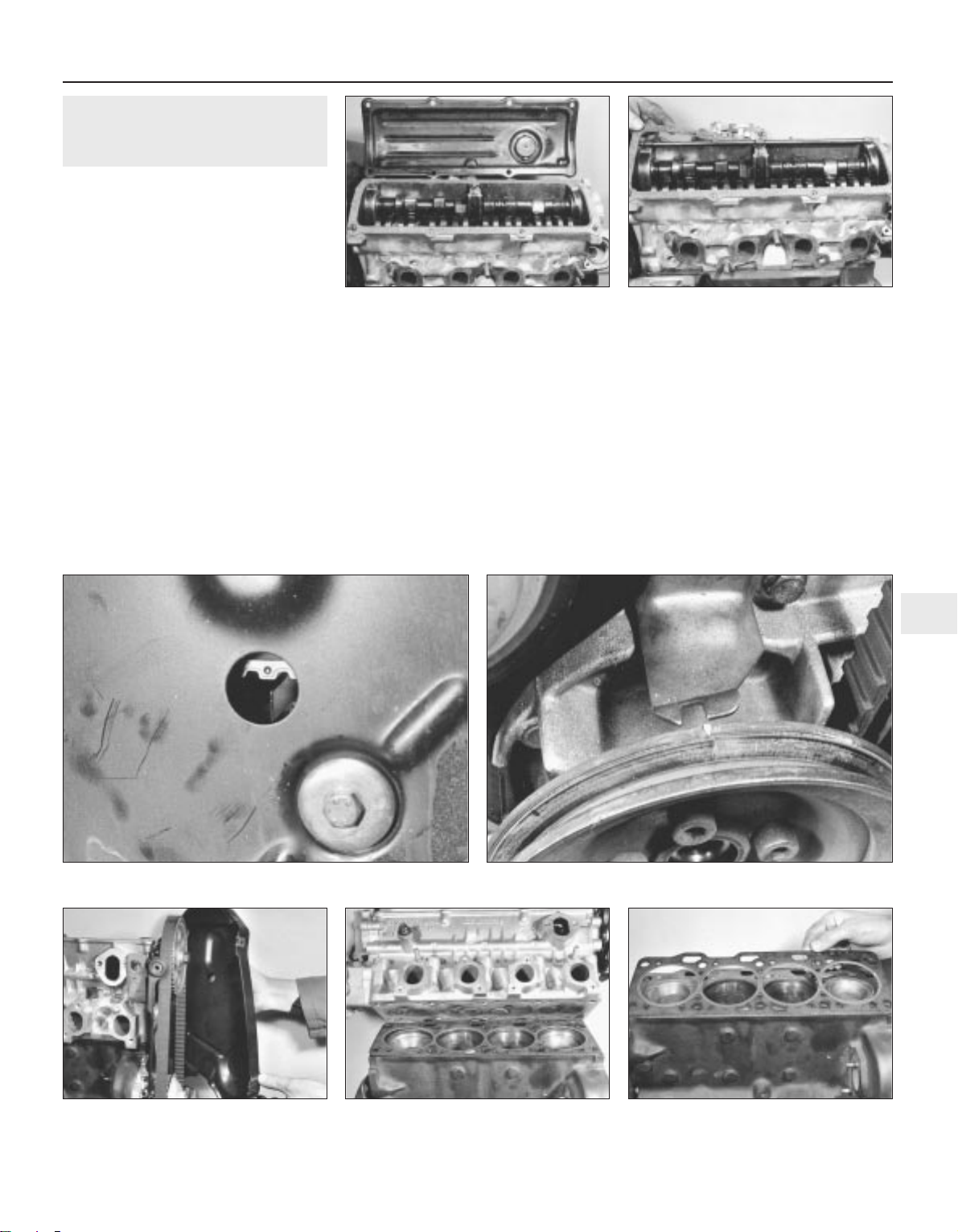
9 Cylinder head - removal
3
1 If the engine is still in the vehicle, first carry
out the following operations:
a) Disconnect the battery negative lead
b) Remove the air cleaner and fuel pump
c) Drain the cooling system and remove the
top hose and thermostat
d) Remove the distributor and spark plugs
e) Remove the inlet and exhaust manifolds.
If necessary, this can be carried out with
the cylinder head on the bench
f) Disconnect the wiring from the coolant
temperature sender and oil pressure
switch
2 Unscrew the nuts and bolts from the valve
cover and remove the cover together with the
gasket and reinforcement strips (see
illustrations).
3 Turn the engine until the indentation in the
camshaft sprocket appears in the TDC hole in
the timing cover and the notch in the
crankshaft pulley is aligned with the TDC
pointer on the front of the oil pump (see
illustrations). Now turn the crankshaft one
quarter of a turn anti-clockwise so that none
of the pistons are at TDC.
4 Unbolt and remove the timing cover (see
illustration), noting that the dipstick tube and
earth lead are fitted to the upper bolts. On
some later 1.3 litre models, it is necessary to
remove the crankshaft pulley to remove the
lower timing belt cover. Pull the dipstick tube
from the cylinder block.
5 Using a socket through the hole in the
camshaft sprocket, unscrew the timing cover
plate upper retaining bolt.
6 Loosen the coolant pump retaining bolts,
then turn the pump body clockwise to release
the tension from the timing belt. Remove the
timing belt from the camshaft sprocket.
7 Remove the bolts and withdraw the timing
cover plate, followed by the coolant pump if
required.
8 Using a splined key, unscrew the cylinder
head bolts half a turn at a time in the reverse
order to that shown for tightening. Note the
location of the engine lifting hooks.
9 Lift the cylinder head from the block (see
illustration). If it is stuck, tap it free with a
wooden mallet. Do not insert a lever as
damage will occur to the joint faces.
10 Remove the gasket from the cylinder
block (see illustration).
Engine repair procedures - 1.05 and 1.3 litre pre August 1985 2A•7
2A
9.2a Removing valve cover. . . 9.2b . . . and gasket
9.4 Removing timing cover 9.9 Removing cylinder head . . . 9.10 . . . and gasket
1081 VW Golf & Jeta
9.3a TDC mark on camshaft sprocket and pointer
9.3b Crankshaft pulley notch aligned with TDC pointer
Page 48
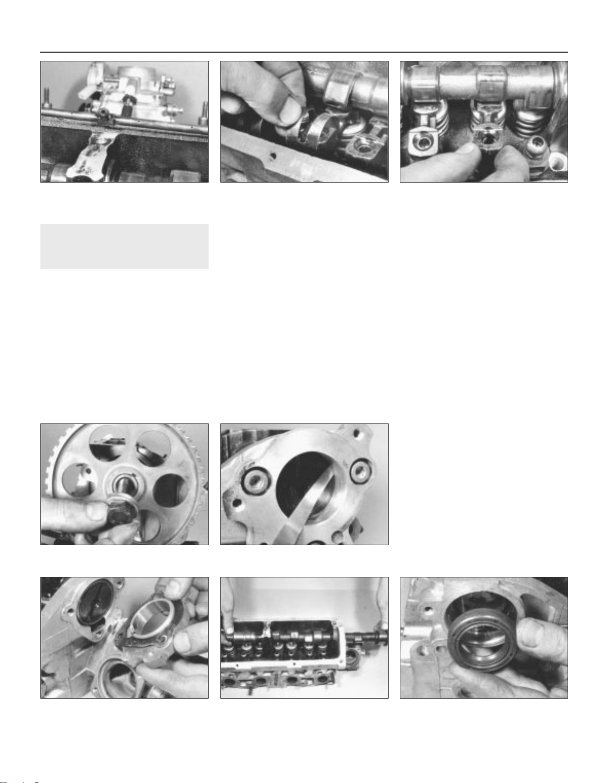
10 Camshaft - removal
3
1 If the engine is still in the vehicle, first carry
out the following operations:
a) Disconnect the battery negative lead
b) Remove the air cleaner and fuel pump
c) Remove the distributor and spark plugs
2 If the cylinder head is still fitted to the
engine, first carry out the procedure
described in paragraphs 3 to 6 inclusive.
3 Unscrew the nuts and bolts from the valve
cover and remove the cover together with the
gasket and reinforcement strips.
4 Turn the engine until the indentation in the
camshaft sprocket appears in the TDC hole in
the timing cover and the notch in the
crankshaft pulley is aligned with the TDC
pointer on the front of the oil pump. Now turn
the crankshaft one quarter of a turn
anti-clockwise so that none of the pistons are
at TDC.
5 Unbolt and remove the timing cover, noting
that the dipstick tube and earth lead are fitted
to the upper bolts. On some later 1.3 litre
models, it is necessary to remove the
crankshaft pulley to remove the lower timing
belt cover.
6 Loosen the coolant pump retaining bolts,
then turn the pump body clockwise to release
the tension from the timing belt. Remove the
timing belt from the camshaft sprocket.
7 Prise the oil spray tube from the top of the
cylinder head (see illustration).
8 Note how the cam follower clips are fitted
then prise them from the ball-studs (see
illustration).
9 Identify each cam follower for location then
remove each one by levering with a
screwdriver. Make sure that the peak of the
relevant cam is pointing away from the
follower first by turning the camshaft as
necessary (see illustration).
10 Unscrew the camshaft sprocket bolt and
remove the spacer (see illustration). The
sprocket can be held stationary using a metal
bar with two bolts, with one bolt inserted in a
hole and the other bolt resting on the outer rim
of the sprocket.
11 Tap the sprocket from the camshaft with a
wooden mallet and prise out the Woodruff
key.
12 Using feeler blades, check the camshaft
endfloat by inserting the blade between the
end of the camshaft and distributor flanges
(see illustration). If it is more than the amount
specified, the components will have to be
checked for wear and renewed as necessary.
13 Using an Allen key, unscrew the bolts and
remove the distributor flange (see
illustration). Remove the gasket.
14 Carefully slide the camshaft from the
cylinder head, taking care not to damage the
three bearing surfaces as the lobes of the
cams pass through them (see illustration).
15 Prise the camshaft oil seal from the
cylinder head (see illustration).
2A•8 Engine repair procedures - 1.05 and 1.3 litre pre August 1985
10.7 Removing oil spray tube 10.8 Removing a cam follower clip 10.9 Removing a cam follower
10.13 Removing distributor flange 10.14 Withdrawing camshaft
10.10 Removing camshaft sprocket bolt
(early type sprocket shown)
10.12 Checking camshaft endfloat
10.15 Removing camshaft oil seal
1081 VW Golf & Jeta
Page 49
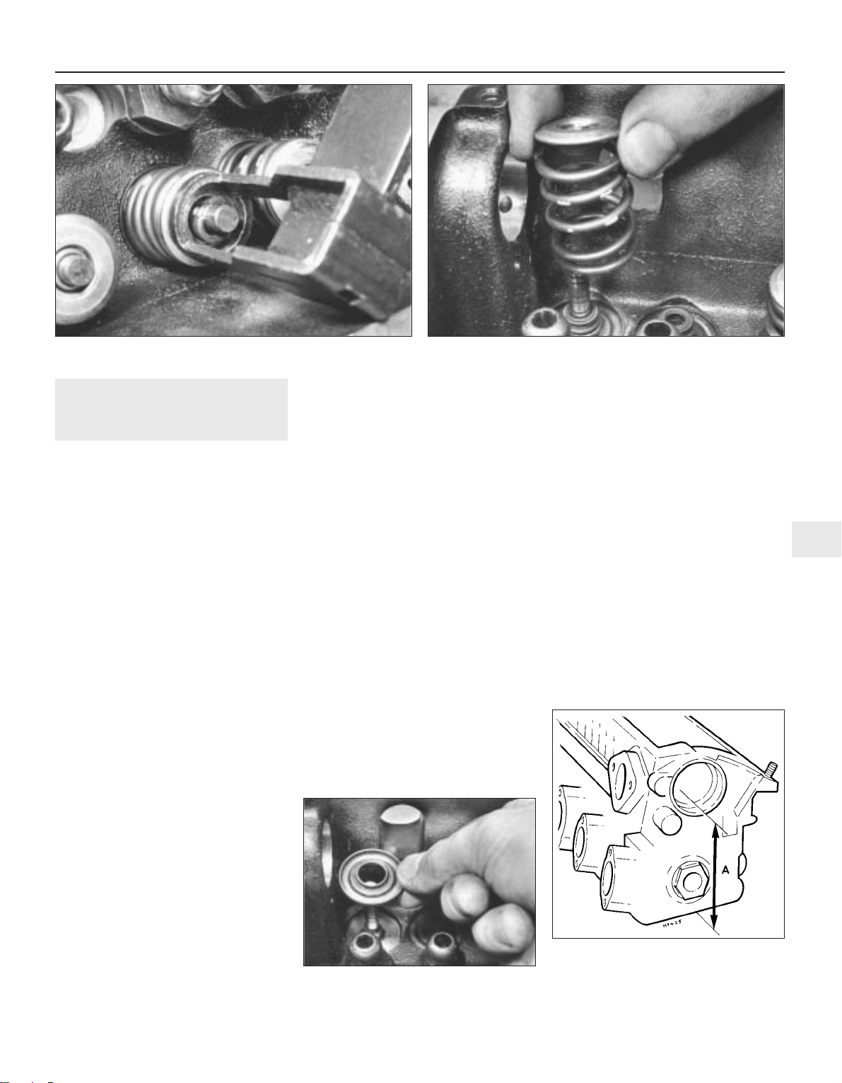
11 Cylinder head - dismantling
and overhaul
3
Dismantling
1 Remove the cylinder head and camshaft, as
described in the previous Sections.
2 Using a valve spring compressor, compress
each valve spring in turn until the split collets
can be removed. Release the compressor and
remove the retainers and springs (see
illustrations). If the retainers are difficult to
remove, do not continue to tighten the
compressor but gently tap the top of the tool
with a hammer. Always make sure that the
compressor is held firmly over the retainer.
3 Remove each valve from the cylinder head,
keeping them identified for location.
4 Prise the valve seals from the valve guides
and remove the lower spring seats (see
illustration).
5 Do not remove the cam follower ball-studs
unless they are unserviceable. They are likely
to be seized in the head.
Overhaul
6 Use a scraper to carefully remove any
carbon from the cylinder head. Remove all
traces of gasket then wash the cylinder head
thoroughly in paraffin and wipe dry.
7 Use a straight-edge and feeler blade to
check that the cylinder head mating surface is
not distorted. If it is, then it must be
resurfaced by a suitably equipped engineering
works. If the cylinder head face is to be
resurfaced, this will necessitate the valve
seats being re-cut so that they are recessed
deeper by an equivalent amount to that
machined from the cylinder head. This is
necessary to avoid the possibility of the valves
coming into contact with the pistons and
causing serious damage and is a task to be
entrusted to a suitably equipped engine
recondition specialist. (see illustration).
8 Examine the valve heads for pitting and
burning. Renew any valve which is badly
burnt. Examine the valve seats at the same
time. If the pitting is very slight, it can be
removed by grinding the valve heads and
seats together with coarse, then fine, grinding
paste. Note that the exhaust valves should not
be re-cut, they should be renewed if the
sealing face is excessively grooved as a result
of regrinding.
9 Where excessive pitting has occurred, the
valve seats must be re-cut or renewed by a
specialist.
10 Valve grinding is carried out as follows.
Place the cylinder head upside down on a
bench with a block of wood at each end.
Smear a trace of coarse carborundum paste
on the seat face and press a suction grinding
tool onto the valve head. With a semi-rotary
action, grind the valve head to its seat, lifting
the valve occasionally to redistribute the
grinding paste. When a dull matt even surface
is produced on both the valve seat and the
valve, wipe off the paste and repeat the
process with fine carborundum paste as
before. A light spring placed under the valve
head will greatly ease this operation. When a
smooth unbroken ring of light grey matt finish
is produced on both the valve and seat, the
grinding operation is complete.
11 Scrape away all carbon from the valve
head stem and clean away all traces of
grinding compound. Clean the valves and
seats with a paraffin-soaked rag, then wipe
with a clean rag.
12 Check for wear in the valve guides. This
may be detected by fitting a new valve in the
guide and checking the amount that the rim of
the valve will move sideways when the top of
the valve stem is flush with the top of the
valve guide. The rock limit for the inlet valve is
1.0 mm and 1.3 mm for the exhaust valve.
This can be measured with feeler blades if you
use a clamp as a datum but it must be with a
new valve. If the rock is at or below this limit
with your old valve then this indicates that the
existing guide(s) do not need renewal. Check
each valve guide in turn but note that the inlet
and exhaust valve stem dimensions differ, so
do not get them confused. If the rock exceeds
the limit with a new valve, this will indicate the
need for new valve guides as well. The
removal and refitting of new guides is a task
which must be entrusted to a specialist.
Engine repair procedures - 1.05 and 1.3 litre pre August 1985 2A•9
2A
11.4 . . . and valve spring lower seats
11.7 Measure cylinder head depth
between points indicated
Minimum allowable depth a = 119.3 mm
1081 VW Golf & Jeta
11.2a Compressing a valve spring to remove split collets
11.2b Removing valve springs and retainers . . .
Page 50
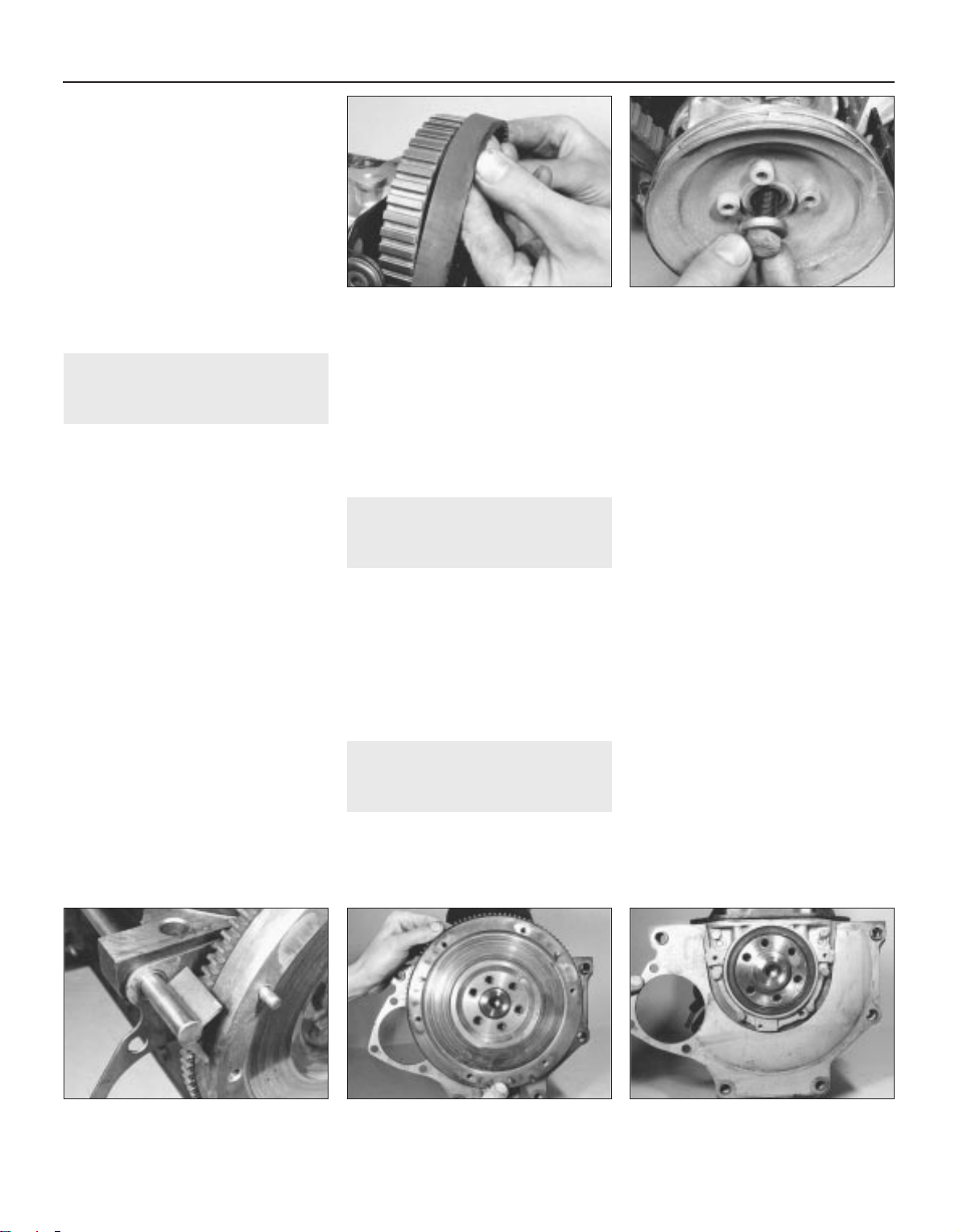
13 If possible, compare the length of the
valve springs with new ones and renew them
as a set if any are shorter.
14 If the engine is still in the vehicle, clean the
piston crowns and cylinder bore upper edges
but make sure that no carbon drops between
the pistons and bores. To do this, locate two
of the pistons at the top of their bores and
seal off the remaining bores with paper and
masking tape. Press a little grease between
the two pistons and their bores to collect any
carbon dust which can be wiped away when
the piston is lowered. To prevent carbon
build-up, polish the piston crown with metal
polish but remove all traces of the polish
afterwards.
12 Timing belt and sprockets -
removal
3
1 If the engine is still in the vehicle, first carry
out the following operations:
a) Disconnect the battery negative lead
b) Remove the air cleaner
c) Remove the alternator drivebelt
2 Turn the engine until the indentation in the
camshaft sprocket appears in the TDC hole in
the timing cover and the notch in the
crankshaft pulley is aligned with the TDC
pointer on the front of the oil pump.
3 Unbolt and remove the timing cover, noting
that the dipstick tube and earth lead are fitted
to the upper bolts. On some later 1.3 litre
models, it is necessary to remove the
crankshaft pulley to remove the lower timing
belt cover.
4 Loosen the coolant pump retaining bolts,
then turn the pump body clockwise to release
the tension from the timing belt. Remove the
timing belt from the camshaft sprocket (see
illustration).
5 Using an Allen key, unbolt the pulley from
the crankshaft sprocket then remove the
timing belt.
6 To remove the camshaft sprocket, unscrew
the bolt and remove the spacer. Tap off the
sprocket and remove the Woodruff key. Do
not turn the camshaft. The sprocket can be
held stationary using a metal bar with two
bolts, with one bolt inserted through a
sprocket hole and the other bolt resting on the
outer rim.
7 To remove the crankshaft sprocket,
unscrew the bolt and lever the sprocket from
the crankshaft (see illustration). Do not turn
the crankshaft otherwise the pistons may
touch the valve heads. Hold the crankshaft
stationary with a lever inserted in the starter
ring gear (remove the starter as applicable).
Remove the Woodruff key.
13 Flywheel - removal
3
1 Remove the clutch.
2 Hold the flywheel stationary with a lever or
angle iron (see illustration) engaged with the
starter ring gear.
3 Unscrew the bolts and lift the flywheel from
the crankshaft (see illustration).
4 Remove the engine plate from the cylinder
block (see illustration).
5 The flywheel bolts must be renewed once
they are removed.
14 Crankshaft oil seals - renewal
3
Front seal
1 Remove the crankshaft sprocket.
2 If available, use VW tool 2085 to remove the
seal from the oil pump housing. Removal of
the seal with the engine and oil pump in
position in the vehicle can prove difficult
without the special tool. In this instance, an
alternative method is to drill two holes,
diagonally opposed to each other in the seal,
insert two self-tapping screws and then pull
on the screws using grips to withdraw the
seal. If using this method, care must be taken
not to drill into the housing.
3 If the oil pump is removed from the engine,
the seal can be prised out and a new item
fitted - see illustration 31.1.
4 Clean the recess in the oil pump.
5 Smear a little clean engine oil on the lip and
outer edge of the new seal, then fit it with VW
tool 10-203 or by tapping it in with a suitable
metal tube .
6 Refit the crankshaft sprocket.
Rear seal
7 Remove the flywheel.
Method 1
8 Drill two diagonally opposite holes in the
seal. Insert two self-tapping screws and pull
out the seal with grips.
9 Clean the recess in the housing.
10 Smear a little clean engine oil on the lip
and outer edge of the new seal then tap it into
the housing using a suitable metal tube
11 Refit the flywheel.
Method 2
12 Remove the sump.
13 Unscrew the bolts and withdraw the
housing from the dowels on the cylinder
block. Remove the gasket (see illustrations).
2A•10 Engine repair procedures - 1.05 and 1.3 litre pre August 1985
12.4 Releasing timing belt from camshaft
sprocket
12.7 Removing crankshaft sprocket bolt
and washer
13.2 One method of holding the flywheel
stationary
13.3 Removing flywheel 13.4 Removing engine plate
1081 VW Golf & Jeta
Page 51
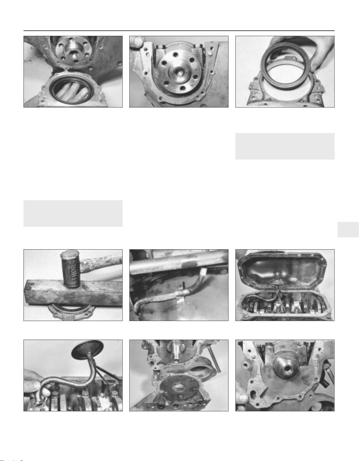
14 Support the housing and drive out the oil
seal (see illustration).
15 Clean the recess in the housing.
16 Smear a little clean engine oil on the lip
and outer edge of the new seal then tap it into
the housing using a block of wood (see
illustration).
17 Clean the mating faces then refit the
housing, together with a new gasket, and
tighten the bolts evenly in diagonal sequence.
18 Refit the sump and flywheel.
15 Sump - removal
3
1 If the engine is still in the vehicle, first carry
out the following operations:
a) Jack up the front of the vehicle and
support it on axle stands (see “Jacking
and vehicle support”). Apply the
handbrake
b) Disconnect the right-hand side driveshaft
and the exhaust system
c) Unclip the alternator wire from the sump
(see illustration)
d) Drain the engine oil into a suitable
container. Clean the drain plug and
washer and refit it, tightening to the
specified torque
2 Unscrew the bolts and withdraw the sump
from the cylinder block (see illustration). If it
is stuck, lever it away or cut through the
gasket with a knife .
3 Scrape the gasket from the sump and
cylinder block.
16 Oil pump - removal
3
1 Remove the timing belt and crankshaft
sprocket.
2 Remove the sump.
3 Unbolt and remove the pick-up tube and
strainer from the oil pump and cylinder block.
Remove the flange gasket (see illustration).
4 Unscrew the bolts and withdraw the oil
pump from the dowels on the front of the
cylinder block. Note that the timing pointed
bracket is located on the two upper central
bolts and the timing belt guard on the two
left-hand side bolts. Remove the gasket (see
illustrations).
Engine repair procedures - 1.05 and 1.3 litre pre August 1985 2A•11
2A
14.13a Withdrawing crankshaft rear oil
seal housing . . .
14.13b . . . and gasket 14.14 Remove crankshaft rear oil seal
from housing
16.3 Removing oil pump pick-up tube and
strainer
16.4a Removing oil pump . . . 16.4b . . . and gasket
14.16 Installing new crankshaft rear oil
seal
15.1 Alternator wire clip on sump 15.2 Removing the sump
1081 VW Golf & Jeta
Page 52
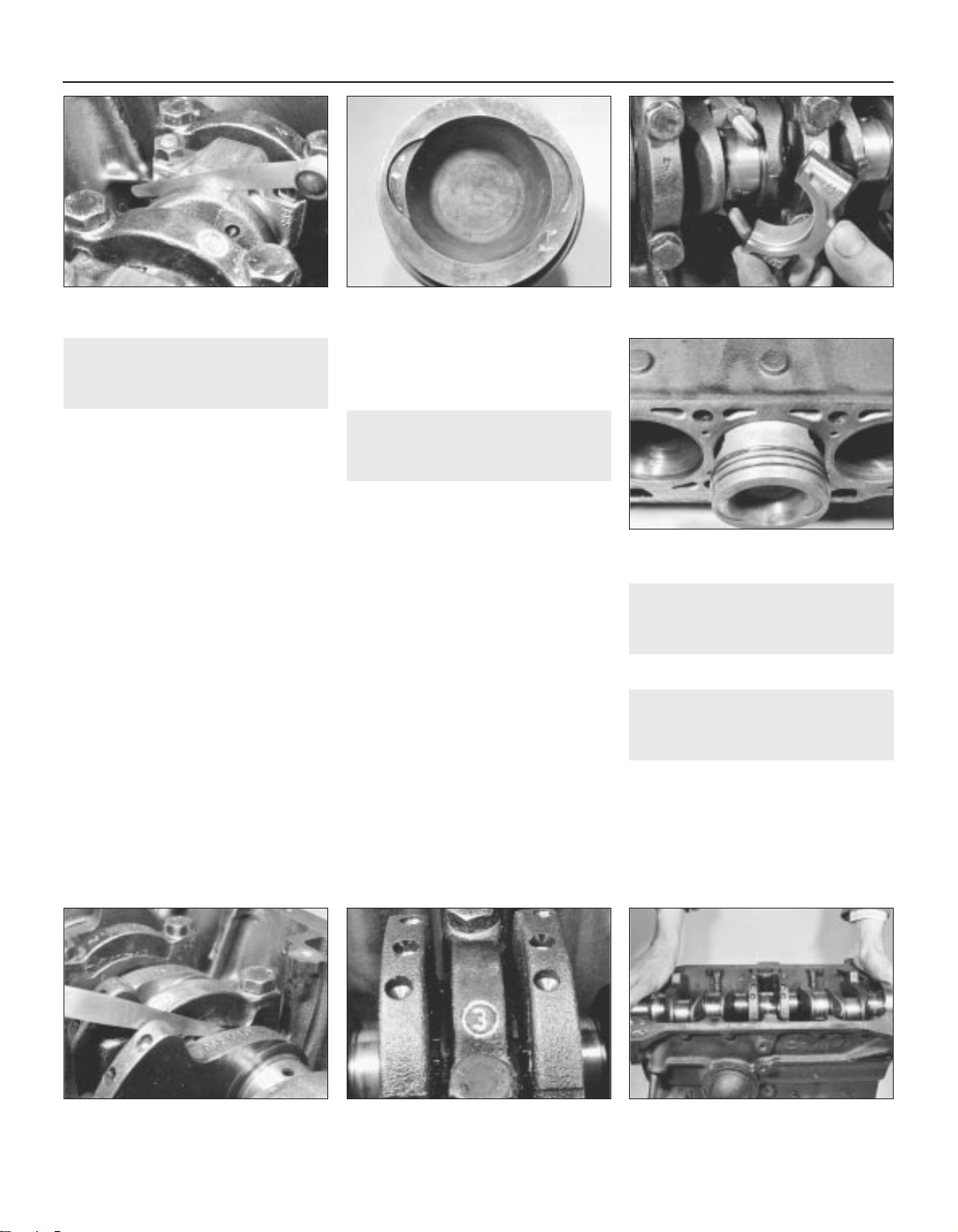
17 Pistons and connecting rods
- removal
3
1 Remove the cylinder head.
2 Remove the sump.
3 Unbolt and remove the pick-up tube and
strainer from the oil pump and cylinder block.
Remove the flange gasket.
4 Using a feeler blade, check that the
connecting rod big-end endfloat on each
crankpin is within the specified limits (see
illustration). If not, the components must be
checked for wear and renewed as necessary.
5 Check the big-end caps and connecting
rods for identification marks, if necessary use
a centre punch to mark them for location and
position. Note that the cut-outs in the
connecting rods and caps face the timing belt
end of the engine. The arrows on the piston
crown also face the timing belt (see
illustration).
6 Turn the crankshaft so that No 1 crankpin is
at its lowest point.
7 Unscrew the big-end nuts and tap free the
cap, together with its bearing shell (see
illustration).
8 Using the handle of a hammer, tap the
piston and connecting rod from the bore and
withdraw it from the top of the cylinder block
(see illustration).
9 Loosely refit the cap to the connecting rod.
10 Repeat the procedure given in paragraphs
7 to 9 on No 4 piston and connecting rod,
then turn the crankshaft through half a turn
and repeat the procedure on No 2 and 3
pistons.
11 Note that during reassembly, the
connecting rod bolts must be renewed.
18 Crankshaft and main
bearings - removal
3
1 Disconnect the connecting rods from the
crankshaft. It is not essential to remove the
pistons or, therefore, to remove the cylinder
head.
2 Remove the oil pump and the rear oil seal
housing.
3 Using a feeler blade, check that the
crankshaft endfloat is within the specified
limits (see illustration). Insert the feeler blade
between the centre crankshaft web and the
thrustwashers. This will indicate whether new
thrustwashers are required or not.
4 Check that the main bearing caps are
identified for location and position. There
should be a cast number in the crankcase
ventilation pipe/coolant coolant pipe side of
the caps, numbered from the timing belt end
of the engine (see illustration).
5 Unscrew the bolts and tap the main bearing
caps free. Keep the bearing shells and where
fitted, the thrustwashers identified for
position.
6 Lift the crankshaft from the crankcase and
remove the remaining bearing shells and
thrustwashers. Keep them identified for
position (see illustration).
19 Oil filter - renewal
1
Refer to Chapter 1, Section 18
20 Examination and renovation
- general information
With the engine completely stripped, clean
all the components and examine them for
wear. Each part should be checked and
where necessary renewed or renovated, as
described in the following Sections. Renew
main and big-end shell bearings as a matter of
course, unless you know that they have had
little wear and are in perfect condition
2A•12 Engine repair procedures - 1.05 and 1.3 litre pre August 1985
17.4 Checking connecting rod endfloat 17.5 Piston crown showing arrow which
points to timing belt end of engine
17.7 Withdrawing a big-end cap
18.3 Checking crankshaft endfloat
17.8 Removing a piston
18.4 Crankshaft main bearing cap
numbering
18.6 Removing crankshaft
1081 VW Golf & Jeta
Page 53
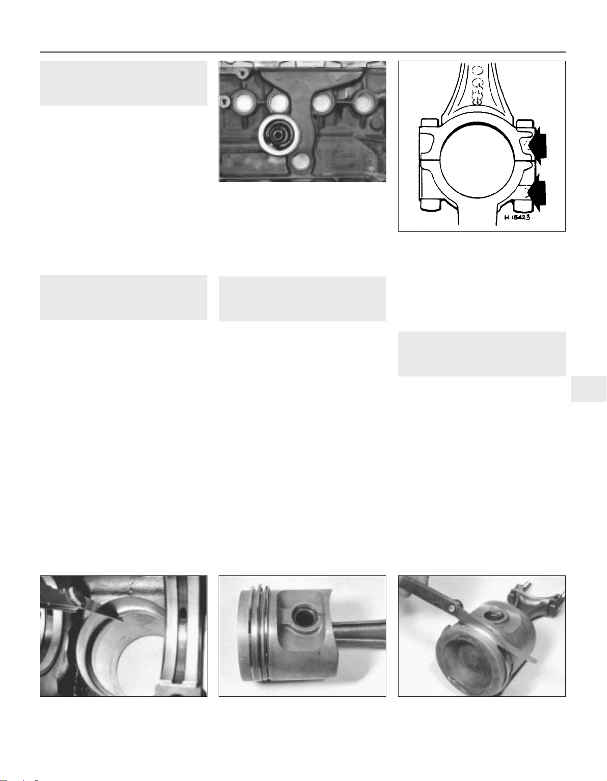
21 Crankshaft and bearings -
examination and renovation
5
1 Examine the bearing surfaces of the
crankshaft for scratches or scoring. Using a
micrometer, check each journal and crankpin
for ovality. Where this is found to be in excess
of 0.17 mm, the crankshaft will have to be
reground and undersize bearings fitted.
2 Crankshaft regrinding should be carried out
by a specialist who will normally supply the
matching undersize main and big-end shell
bearings.
3 If crankshaft endfloat is more than the
maximum specified amount, new centre main
bearing shells with side flanges will have to be
fitted to replace the thrustwashers. These are
usually supplied together with the main and
big-end bearings on a reground crankshaft.
22 Cylinder block/crankcase -
examination and renovation
5
1 The cylinder bores must be examined for
taper, ovality, scoring and scratches. Start by
examining the top of the bores. If these are
worn, a slight ridge will be found which marks
the top of the piston ring travel. If the wear is
excessive, the engine will have had a high oil
consumption rate accompanied by blue
smoke from the exhaust.
2 If available, use an inside dial gauge to
measure the bore diameter just below the
ridge and compare it with the diameter at the
bottom of the bore, which is not subject to
wear. If the difference is more than 0.15 mm,
the cylinders will normally require reboring
with new oversize pistons fitted.
3 If cylinder bore wear does not exceed 0.20
mm, special oil control rings and pistons can
be fitted to restore compression and stop the
engine burning oil.
4 If new pistons are being fitted to old bores,
it is essential to roughen the bore walls
slightly with fine glasspaper to enable the new
piston rings to bed in properly.
5 Thoroughly examine the crankcase and
cylinder block for cracks and damage and use
a piece of wire to probe all oilways and
waterways to ensure that they are
unobstructed.
6 Check the core plugs for leaks and security
(see illustration).
23 Pistons and connecting rods
- examination and renovation
4
1 Examine the pistons for ovality, scoring and
scratches. Check the connecting rods for
wear and damage.
2 To remove the pistons from the connecting
rods, first mark the two components in
relation to each other. The indentation on the
bearing end of the connecting rod faces the
same way as the arrow on the piston crown
(see illustration).
3 Prise out the circlips then dip the piston in
hot water. Press out the gudgeon pin and
separate the piston from the connecting rod.
4 Assemble the pistons in reverse order.
5 If new rings are to be fitted to the original
pistons, expand the old rings over the top of
the pistons by using three old feeler blades to
prevent the rings dropping into empty
grooves.
6 Before fitting the new rings, insert each of
them into the cylinder bore approximately
15.0 mm from the bottom and check that the
end gaps are as specified (see illustration).
7 When fitting the rings to the pistons, ensure
that the TOP markings face towards the
piston crown and arrange the end gaps at
120° intervals (see illustration). Using a feeler
blade, check that the clearance of each ring in
its groove is within the limits specified (see
illustration).
24 Oil pump - examination and
renovation
3
Note: The manufacturer does not supply any
clearances for checking oil pump gear wear,
so the pump must be assumed to be in good
order provided that oil pressure is as
specified. Pressure can only be checked with
the engine assembled and the task should be
entrusted to a VW garage. A visual
examination of the oil pump can be made as
follows:
1 Using an Allen key, unscrew the relief valve
plug and extract the spring and plunger (see
illustrations).
2 Using an impact screwdriver, remove the
cross-head screws and withdraw the cover
from the pump (see illustration).
3 Remove the rotors, noting that the
indentation on the outer rotor faces the cover
(see illustrations).
Engine repair procedures - 1.05 and 1.3 litre pre August 1985 2A•13
2A
22.6 Core plugs in cylinder block
23.2 Indentations on big-end bearings
(arrowed) must face same way as arrow on
piston crown
23.6 Checking piston ring gaps 23.7a Space ring gaps at 120° intervals 23.7b Checking piston ring-to-groove wall
clearance
1081 VW Golf & Jeta
Page 54
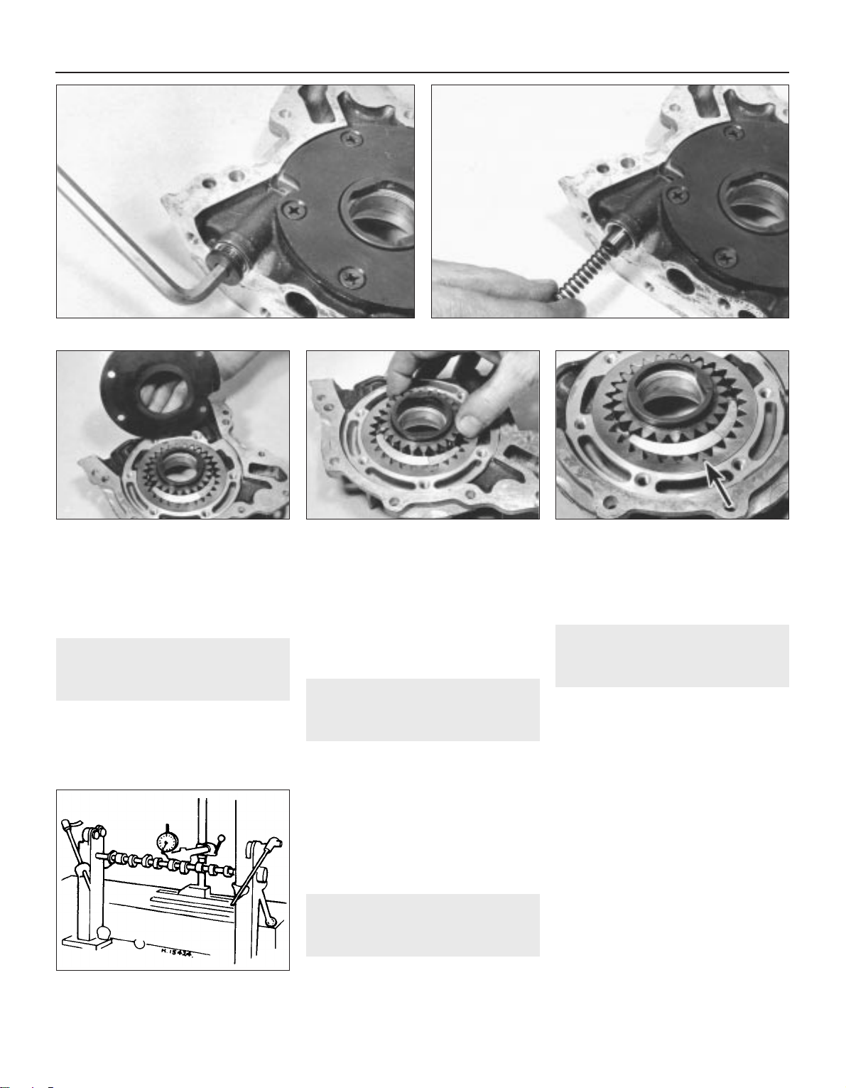
4 Clean the components in paraffin and wipe
dry, then examine them for wear and damage.
If evident, renew the oil pump complete but if
in good order, reassemble the pump in reverse
order and tighten the screws and plug.
25 Flywheel - examination and
renovation
4
1 A damaged flywheel must be renewed.
2 Inspect the starter ring teeth. If these are
chipped or worn it is possible to renew the
starter ring. This means heating the ring until it
may be separated from the flywheel, or
alternatively splitting it. A new ring must then be
shrunk on. If you know how to do this and you
can get a new ring, then the job can be done
but it is beyond the capacity of most owners.
3 Serious scoring on the flywheel clutch
facing again requires a new flywheel. Do not
attempt to clean the scoring off with a scraper
or emery.
26 Timing belt and sprockets -
examination and renovation
1
1 The timing belt should be renewed as a
matter of course at 40 000 miles (60 000 km),
see Chapter 1.
2 The full length of the timing belt must be
checked for signs of uneven wear, splitting or
oil contamination. Renew the belt if there is
the slightest doubt about its condition.
3 The camshaft and crankshaft sprockets do
not normally require renewal as wear takes
place very slowly.
27 Camshaft - examination and
renovation
3
Examine the camshaft bearing surfaces,
cam lobes and followers for wear. If wear is
excessive, renew the camshaft and followers.
Check the camshaft run-out by turning it
between fixed centres with a dial gauge on
the centre journal. If the run-out exceeds that
specified, renew the shaft (see illustration).
28 Engine reassembly - general
information
To ensure maximum life with minimum
trouble from a rebuilt engine, adhere to the
following:
a) Ensure that all components are spotlessly
clean
b) Ensure that all oilways are clear
c) Ensure lockwashers are fitted where
indicated
d) Lubricate all bearings and other working
surfaces thoroughly with clean engine oil
during assembly
e) Renew any bolts or studs with damaged
threads.
f) Gather together a torque wrench, oil can
and some clean rags
g) Obtain a set of engine gaskets and oil
seals, together with a new oil filter
2A•14 Engine repair procedures - 1.05 and 1.3 litre pre August 1985
24.2 Removing oil pump cover . . . 24.3a . . . and rotors 24.3b Outer rotor indentation (arrowed)
must face cover
27.2 Checking camshaft run-out
1081 VW Golf & Jeta
24.1a Unscrew relief valve plug . . .
24.1b . . . and remove spring and plunger
Page 55
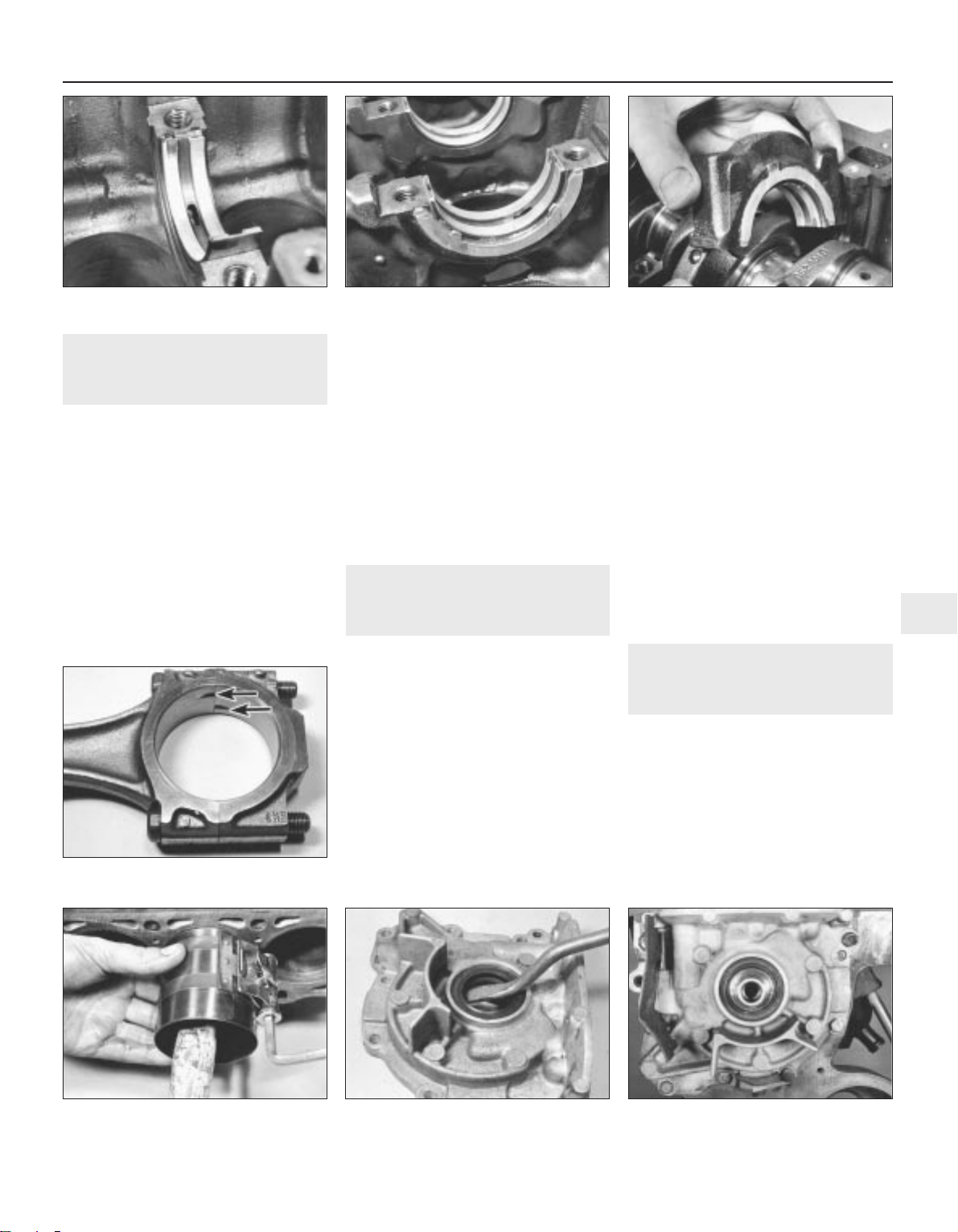
29 Crankshaft and main
bearings - refitting
3
1 Clean the backs of the bearing shells and
the bearing recesses in the cylinder block and
main bearing caps.
2 Press the main bearing shells into the
cylinder block and caps and oil them liberally
(see illustration).
3 Where thrustwashers are being refitted
(instead of a shouldered type No 3 main
bearing shell, a plain shell is used), smear the
washers with grease and stick them into
position on the side of the centre main
bearing and its cap (see illustration). The
washers must be fitted so that their oilways
face away from the bearings in the block and
cap.
4 Lower the crankshaft into position, then fit
the main bearing caps in their previously
noted positions (see illustration). Note that
the bearing shell lugs are adjacent to each
other.
5 Insert the bolts and tighten them evenly to
the specified torque. Check that the
crankshaft rotates freely then check that the
endfloat is within the specified limits by
inserting a feeler blade between the centre
crankshaft web and the thrustwashers or
bearing shoulder, as applicable.
6 Refit the rear oil seal bearing and oil pump
and reconnect the connecting rods.
30 Pistons and connecting rods
- refitting
3
1 As mentioned during removal, the
manufacturers recommend that the
connecting rod bolts be renewed. Assemble
the new bolts to the rods.
2 Clean the backs of the bearing shells and
the recesses in the connecting rods and
big-end caps.
3 Press the big-end bearing shells into the
connecting rods and caps in their correct
positions and oil them liberally (see
illustration).
4 Fit a ring compressor to No 1 piston then
insert the piston and connecting rod into No 1
cylinder (see illustration). With No 1 crankpin
at its lowest point, drive the piston carefully
into the cylinder with the wooden handle of a
hammer and at the same time, guide the
connecting rod into the crankpin. Make sure
that the arrow on the piston crown faces the
timing belt end of the engine.
5 Fit the big-end bearing cap in its previously
noted position then fit the nuts and tighten
them evenly to the specified torque.
6 Check that the crankshaft turns freely and
use a feeler blade to check that the
connecting rod endfloat is within the specified
limits.
7 Repeat the procedure given in paragraphs
3 to 5 for No 4 piston and connecting rod,
then turn the crankshaft through half a turn
and repeat the procedure for No 2 and 3
pistons.
8 If the engine is in the vehicle, refit the oil
pump pick-up tube and strainer, the sump
and the cylinder head.
31 Oil pump - refitting
3
1 Renew the oil seal in the oil pump housing
(see illustration).
2 Locate a new gasket on the dowels on the
front of the cylinder block.
3 Locate the oil pump on the block, making
sure that the inner rotor engages the flats on
the crankshaft. Do not damage the oil seal.
4 Insert the bolts, together with the timing
pointer bracket and timing belt guard, then
tighten them evenly to the specified torque
(see illustration).
Engine repair procedures - 1.05 and 1.3 litre pre August 1985 2A•15
2A
29.2 Fitting centre main bearing shell 29.3 Thrustwasher location on centre
main bearing
29.4 Fitting centre main bearing cap
30.3 Correct location of tabs on big-end
bearings (arrowed)
30.4 Using a piston ring compressor 31.1 Prising out oil pump oil seal 31.4 Fitted location of oil pump
1081 VW Golf & Jeta
Page 56
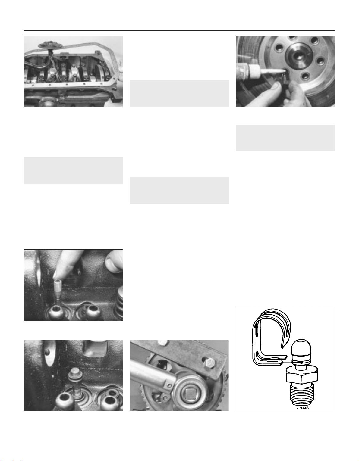
5 Locate a new gasket on the flange face
then fit the pick-up tube and strainer. Insert
the bolts and tighten them to the specified
torque.
6 Refit the sump, timing belt and sprocket.
32 Sump - refitting
3
1 If applicable (ie. the engine has been
dismantled), refit the crankshaft rear oil seal
and housing.
2 Clean the mating faces of the sump and
cylinder block.
3 Locate the new gasket on the block (see
illustration) then fit the sump. Insert the sump
bolts and tighten them evenly in diagonal
sequence to the specified torque. If required,
the two bolts at the flywheel end of the sump
can be replaced by socket-headed bolts to
facilitate their removal with the engine in the
vehicle. Note that the tightening torque for the
replacement bolts is 8 Nm (6 Ibf ft).
4 If the engine is in the vehicle, replenish it
with oil, fasten the alternator wire to the sump
clip and lower the vehicle to the ground.
33 Flywheel - refitting
3
1 Locate the engine plate on the cylinder
block dowels.
2 Clean the mating faces of the flywheel and
crankshaft then locate the flywheel in position.
Note that the bolt holes only align in one
position as they are offset.
3 Apply locking fluid to the threads of new
bolts (see illustration) then insert and tighten
them in a diagonal sequence to the specified
torque while holding the flywheel stationary.
4 Refit the clutch.
34 Cylinder head - reassembly
3
1 Fit the valves into their correct locations in
the cylinder head.
2 Working on each valve at a time, locate the
valve spring lower seat in position.
3 Before fitting each valve seal, locate the
special plastic sleeve provided in the gasket
set over the valve stem in order to prevent
damage to the seal (see illustration).
4 Slide each new seal over the valve stem
and press it firmly onto the guide using a
metal tube (see illustration). Remove the
plastic sleeve.
5 Fit the spring and retainer over each valve
stem, then compress the spring with the
compressor and insert the split collets.
Release the compressor and remove it.
6 Refit the camshaft.
35 Camshaft - refitting
3
1 Smear a little clean engine oil on the lip and
outer edge of the camshaft oil seal then drive
it squarely into the cylinder head with a block
of wood.
2 Oil the camshaft bearing surfaces then slide
the camshaft into position, taking care not to
damage the oil seal.
3 Fit the distributor flange, together with a
new gasket, and tighten the socket-head
bolts.
4 Using a feeler blade, check that the
camshaft endfloat is as specified.
5 Fit the Woodruff key then fit the sprocket to
the camshaft followed by the spacer and bolt.
Tighten the bolt while holding the sprocket
stationary with a metal bar and two bolts (see
illustration).
6 Fit the cam followers by turning the
camshaft so that the relevant cam lobe peak
is pointing away from the valve, then tap the
follower between the valve stem and cam and
onto the ball-stud.
7 Slide the cam follower clips into the
grooves on the ball studs and locate the
upper ends on the cam followers (see
illustration).
2A•16 Engine repair procedures - 1.05 and 1.3 litre pre August 1985
32.3 Fitting sump gasket 33.3 Applying liquid locking fluid to
flywheel bolts
34.3 Locate plastic sleeve on valve
stem . . .
34.4 . . . then fit the new oil seal 35.5 Method of tightening camshaft
sprocket bolt
35.7 Cam follower clip and groove in
ball-stud
1081 VW Golf & Jeta
Page 57
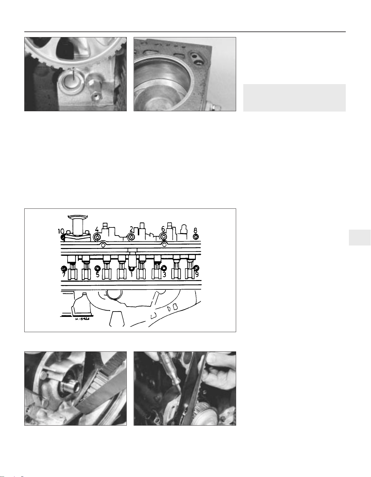
8 Adjust the valve clearances.
9 Turn the camshaft so that the indentation in
the sprocket is pointing downwards and in
line with the pointer on the timing cover plate
(see illustration).
10 Turn the crankshaft a quarter of a turn
clockwise so that the notch in the crankshaft
pulley is aligned with the TDC pointer on the
front of the oil pump.
11 Fit the timing belt to the camshaft
sprocket and coolant pump.
12 Using a screwdriver in the coolant pump,
turn the pump anti-clockwise and tension the
timing belt until it can just be turned through
90° with the thumb and forefinger midway
between the camshaft sprocket and coolant
pump.
13 Tighten the coolant pump bolts when the
belt tension is correct and check the timing
marks are still aligned.
14 Fit the dipstick tube to the cylinder block.
15 Fit the timing cover, insert the bolts with
the earth lead and dipstick tube bracket, then
tighten the bolts.
16 Press the oil spray tube into the top of the
cylinder head.
17 Refit the valve cover with a new gasket,
locate the reinforcement strips and tighten the
nuts and bolts.
18 If the engine is in the vehicle, reverse the
preliminary procedures given in Section 10.
36 Cylinder head - refitting
3
1 Position Nos 1 and 4 pistons at TDC then
turn the crankshaft a quarter of a turn
anti-clockwise so that neither of the pistons is
at TDC.
2 Ensure that the faces of the cylinder head
and block are perfectly clean then locate the
new gasket on the block, making sure that all
oil and coolant holes are visible. The gasket
part number should be uppermost (see
illustration).
3 Lower the cylinder head onto the gasket
then insert the bolts together with the engine
lifting hooks.
4 Using a splined key, tighten the bolts in the
stages given in Specifications, using the
sequence shown (see illustration).
5 Refit the coolant pump, if applicable.
6 Fit the timing cover plate and insert the
coolant pump bolts loosely.
7 If required, refit the camshaft.
8 Refit and tighten the timing cover plate
upper retaining bolt.
9 If applicable, refit the crankshaft sprocket
and timing belt to the crankshaft (see
illustration).
10 Turn the camshaft so that the indentation
in the sprocket is aligned with the pointer on
the timing cover plate.
11 Turn the crankshaft a quarter of a turn
clockwise so that the notch in the crankshaft
pulley (temporarily refit if necessary) is aligned
with the TDC pointer on the front of the oil
pump.
12 Fit the timing belt to the camshaft
sprocket and coolant pump.
13 Using a screwdriver in the coolant pump,
turn the pump anti-clockwise and tension the
timing belt until it can just be turned through
90° with the thumb and forefinger midway
between the camshaft sprocket and coolant
pump (see illustration).
14 Tighten the coolant pump bolts when the
tension is correct and check that the timing
marks are still aligned.
15 Fit the dipstick tube to the cylinder block.
16 Fit the timing cover, insert the bolts with
the earth lead and dipstick tube bracket and
tighten the bolts.
17 Refit the valve cover with a new gasket,
locate the reinforcement strips and tighten the
nuts and bolts.
18 If the engine is in the vehicle, reverse the
preliminary procedures given in Section 9.
Engine repair procedures - 1.05 and 1.3 litre pre August 1985 2A•17
2A
35.9 Camshaft sprocket (later type) with
index mark aligned with timing cover TDC
pointer
36.2 Correct fitting of cylinder head
gasket
36.4 Cylinder head bolt tightening sequence
36.9 Fitting crankshaft sprocket and
timing belt
36.13 Tensioning timing belt
1081 VW Golf & Jeta
Page 58
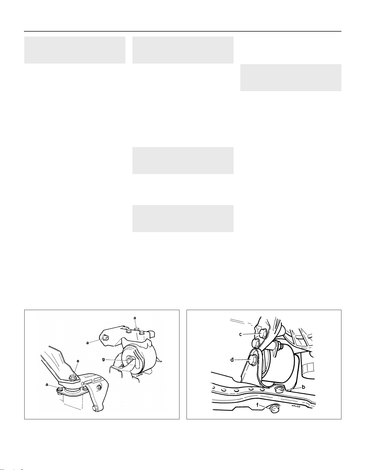
37 Timing belt and sprockets -
refitting
3
1 Fit the Woodruff key in the crankshaft and
tap the sprocket into position .
2 Insert the bolt and tighten it to the specified
torque while holding the crankshaft stationary
with a lever in the starter ring gear.
3 Fit the Woodruff key to the camshaft then fit
the sprocket followed by the spacer and bolt.
Tighten the bolt while holding the sprocket
stationary with a metal bar and two bolts.
4 Locate the timing belt on the crankshaft
sprocket then fit the pulley. Insert the bolts
and tighten them with an Allen key.
5 Turn the camshaft so that the indentation in
the sprocket is aligned with the pointer on the
timing cover plate. Check that the notch in the
crankshaft pulley is aligned with the TDC
pointer on the front of the oil pump
6 Fit the timing belt to the camshaft sprocket
and coolant pump.
7 Using a screwdriver in the coolant pump,
turn the pump anti-clockwise and tension the
timing belt until it can just be turned through
90° with the thumb and forefinger midway
between the camshaft sprocket and coolant
pump.
8 Tighten the coolant pump bolts when the
belt tension is correct and check that the
timing marks are still aligned.
9 Fit the timing cover, insert the bolts with the
earth lead and dipstick tube bracket, then
tighten the bolts.
10 If the engine is in the vehicle, reverse the
preliminary procedures given in Section 12.
38 Valve clearances - checking
and adjustment
3
1 The valve clearances can be checked and
adjusted with the cylinder head removed
(prior to refitting after overhaul) or in the
normal manner described in Section 12 of
Chapter 1.
2 There are two specified valve clearance
settings, these being for a cold (cylinder head
removed) or warm (engine in vehicle) engine
condition.
3 If the valve clearances are adjusted with the
engine cold, recheck the clearances again
after 600 miles (900 km) with the engine at its
normal operating temperature.
39 Engine ancillary components
and gearbox - refitting
3
Refer to Section 8 and refit the listed
ancillary components.
Refit the gearbox to the engine, reversing
the procedures described in Section 6.
40 Engine - refitting
4
Reverse the removal procedure given in
Section 5 but note the following additional
points:
a) When lowering the engine/gearbox unit
into the vehicle, ensure that the
driveshafts are aligned with the flanges
b) Assemble the engine mountings loosely
initially and tighten them only after the
unit is central without straining the
mountings (see illustrations)
c) Adjust the clutch
d) Adjust the accelerator cable and, where
applicable, the choke cable
e) Refill the engine with oil and coolant
41 Engine - adjustments after
major overhaul
2
1 With the engine/gearbox unit fitted to the
vehicle, make a final check to ensure that
everything has been reconnected and that no
rags or tools have been left in the engine
compartment.
2 If new pistons or crankshaft bearings have
been fitted, turn the carburettor engine speed
screw in about half a turn to compensate for
the initial tightness of the new components.
3 Fully pull out the choke (manual choke
models) and start the engine. This may take a
little longer than usual as the fuel pump and
carburettor float chamber may be empty.
4 As soon as the engine starts, push in the
choke to the detent. Check that the oil
pressure light goes out.
5 Check the oil filter, fuel hoses and coolant
hoses for leaks.
6 Run the engine to normal operating
temperature, then adjust the slow running
(idle).
7 If new pistons or crankshaft bearings have
been fitted, the engine must be run-in for the
first 500 miles (750 km). Do not operate the
engine at full throttle or allow the engine to
labour in any gear.
8 Although not strictly essential, it is good
practice to change the engine oil and filter
after the initial running-in period. This will get
rid of the small metallic particles which are
produced by new components bedding in to
each other.
2A•18 Engine repair procedures - 1.05 and 1.3 litre pre August 1985
1081 VW Golf & Jeta
40.1a Engine mounting bolt identification see Specifications for torque settings
40.1b Engine/transmission mounting bolt identification see Specifications for torque settings
Page 59

1081 VW Golf & Jetta
2B
Chapter 2 Part B:
Engine repair procedures -
1.05 and 1.3 litre post August 1985
The following information is a revision of, or supplementary to, that contained in Part A of this Chapter
General
Code:
1.05 litre . . . . . . . . . . . . . . . . . . . . . . . . . . . . . . . . . . . . . . . . . . . . . . . HZ
1.3 litre . . . . . . . . . . . . . . . . . . . . . . . . . . . . . . . . . . . . . . . . . . . . . . . . MH
1.3 litre . . . . . . . . . . . . . . . . . . . . . . . . . . . . . . . . . . . . . . . . . . . . . . . . NZ
1.3 litre . . . . . . . . . . . . . . . . . . . . . . . . . . . . . . . . . . . . . . . . . . . . . . . . 2G
Cylinder head
Minimum dimension after machining (skimming) . . . . . . . . . . . . . . . . . . 135.6 mm
Camshaft
Maximum run-out . . . . . . . . . . . . . . . . . . . . . . . . . . . . . . . . . . . . . . . . . . 0.01 mm
Maximum radial play . . . . . . . . . . . . . . . . . . . . . . . . . . . . . . . . . . . . . . . . 0.10 mm
Valves
Maximum seat width . . . . . . . . . . . . . . . . . . . . . . . . . . . . . . . . . . . . . . . 2.2 mm
Head diameter:
Inlet . . . . . . . . . . . . . . . . . . . . . . . . . . . . . . . . . . . . . . . . . . . . . . . . . . . 36.0 mm
Exhaust . . . . . . . . . . . . . . . . . . . . . . . . . . . . . . . . . . . . . . . . . . . . . . . . 29.0 mm
Valve length:
Inlet . . . . . . . . . . . . . . . . . . . . . . . . . . . . . . . . . . . . . . . . . . . . . . . . . . . 98.9 mm
Exhaust . . . . . . . . . . . . . . . . . . . . . . . . . . . . . . . . . . . . . . . . . . . . . . . . 99.1 mm
Hydraulic tappets
Maximum free travel . . . . . . . . . . . . . . . . . . . . . . . . . . . . . . . . . . . . . . . . 0.1 mm
Valve timing
Nil valve clearance at 1.0 mm valve lift MH/NZ/2G HZ
Inlet opens . . . . . . . . . . . . . . . . . . . . . . . . . . . . . . . . . . . . . . . . . . . . . . . 12°ATDC 5°ATDC
Inlet closes . . . . . . . . . . . . . . . . . . . . . . . . . . . . . . . . . . . . . . . . . . . . . . . 28°ABDC 29°ABDC
Exhaust opens . . . . . . . . . . . . . . . . . . . . . . . . . . . . . . . . . . . . . . . . . . . . 25°BBDC 33°BBDC
Exhaust closes . . . . . . . . . . . . . . . . . . . . . . . . . . . . . . . . . . . . . . . . . . . . 9°BTDC 9°BTDC
Camshaft - examination . . . . . . . . . . . . . . . . . . . . . . . . . . . . . . . . . . 8
Camshaft - refitting . . . . . . . . . . . . . . . . . . . . . . . . . . . . . . . . . . . . . . 10
Camshaft - removal . . . . . . . . . . . . . . . . . . . . . . . . . . . . . . . . . . . . . . 4
Camshaft oil seal - renewal . . . . . . . . . . . . . . . . . . . . . . . . . . . . . . . . 3
Cylinder head - dismantling and overhaul . . . . . . . . . . . . . . . . . . . . . 5
Cylinder head - refitting . . . . . . . . . . . . . . . . . . . . . . . . . . . . . . . . . . . 11
Cylinder head - removal . . . . . . . . . . . . . . . . . . . . . . . . . . . . . . . . . . 2
Engine - adjustments after major overhaul . . . . . . . . . . . . . . . . . . . . 13
General information . . . . . . . . . . . . . . . . . . . . . . . . . . . . . . . . . . . . . . 1
Hydraulic bucket tappets - checking free travel . . . . . . . . . . . . . . . . 12
Oil pump - refitting . . . . . . . . . . . . . . . . . . . . . . . . . . . . . . . . . . . . . . . 9
Oil pump - removal and examination . . . . . . . . . . . . . . . . . . . . . . . . 7
Timing belt and sprockets - removal . . . . . . . . . . . . . . . . . . . . . . . . . 6
2B•1
Specifications
Contents
Easy, suitable for
novice with little
experience
Fairly easy, suitable
for beginner with
some experience
Fairly difficult,
suitable for competent
DIY mechanic
Difficult, suitable for
experienced DIY
mechanic
Very difficult,
suitable for expert DIY
or professional
Degrees of difficulty
5
4
3
2
1
Page 60
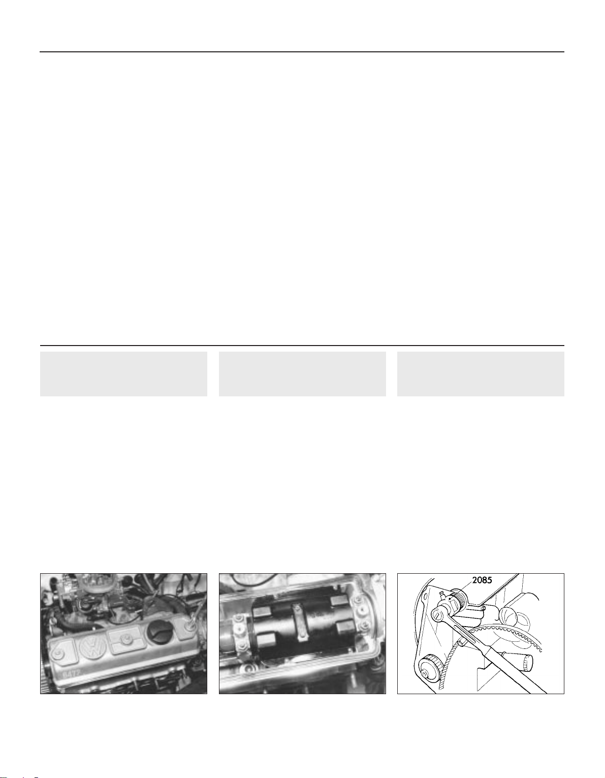
Lubrication system
Pump gear teeth backlash:
New . . . . . . . . . . . . . . . . . . . . . . . . . . . . . . . . . . . . . . . . . . . . . . . . . . . 0.05 mm
Wear limit . . . . . . . . . . . . . . . . . . . . . . . . . . . . . . . . . . . . . . . . . . . . . . 0.20 mm
Pump gear teeth axial play (wear limit) . . . . . . . . . . . . . . . . . . . . . . . . . . 0.15 mm
Pump chain drive deflection . . . . . . . . . . . . . . . . . . . . . . . . . . . . . . . . . . 1.5 to 2.5 mm
Torque wrench settings Nm Ibf ft
Camshaft sprocket bolt . . . . . . . . . . . . . . . . . . . . . . . . . . . . . . . . . . . . . 80 59.0
Timing belt cover:
Upper bolt . . . . . . . . . . . . . . . . . . . . . . . . . . . . . . . . . . . . . . . . . . . . . . 10 7.3
Lower bolt . . . . . . . . . . . . . . . . . . . . . . . . . . . . . . . . . . . . . . . . . . . . . . 20 14.7
Camshaft bearing cap nuts:
Stage 1 . . . . . . . . . . . . . . . . . . . . . . . . . . . . . . . . . . . . . . . . . . . . . . . . 6 4.4
Stage 2 . . . . . . . . . . . . . . . . . . . . . . . . . . . . . . . . . . . . . . . . . . . . . . . . Tighten by further 90°
Number 5 cap screws . . . . . . . . . . . . . . . . . . . . . . . . . . . . . . . . . . . . . . . 10 7.3
Cylinder head bolts:
Stage 1 . . . . . . . . . . . . . . . . . . . . . . . . . . . . . . . . . . . . . . . . . . . . . . . . 40 29.5
Stage 2 . . . . . . . . . . . . . . . . . . . . . . . . . . . . . . . . . . . . . . . . . . . . . . . . 60 44.3
Stage 3 . . . . . . . . . . . . . . . . . . . . . . . . . . . . . . . . . . . . . . . . . . . . . . . . Tighten by further 180°
Oil pump bolts . . . . . . . . . . . . . . . . . . . . . . . . . . . . . . . . . . . . . . . . . . . . 20 14.7
Stay bracket bolts . . . . . . . . . . . . . . . . . . . . . . . . . . . . . . . . . . . . . . . . . . 10 7.3
Strainer assembly to pump body . . . . . . . . . . . . . . . . . . . . . . . . . . . . . . 10 7.3
Socket-headed screws in sump (new) . . . . . . . . . . . . . . . . . . . . . . . . . . 8 5.9
Crankshaft sprocket bolt (oiled) - 1986-on:
Stage 1 . . . . . . . . . . . . . . . . . . . . . . . . . . . . . . . . . . . . . . . . . . . . . . . . 90 66
Stage 2 . . . . . . . . . . . . . . . . . . . . . . . . . . . . . . . . . . . . . . . . . . . . . . . . Tighten by further 180°
Flywheel bolt (with shoulder) . . . . . . . . . . . . . . . . . . . . . . . . . . . . . . . . . 100 74
1 General information
The 1.05 and 1.3 litre engines produced
since August 1985 have a redesigned cylinder
head which incorporates hydraulic “bucket”
type tappets in place of the previously fitted
“rocker finger” tappets.
The oil pump has also been changed from
the previously fitted crescent type to a gear
type which is driven by chain from the
crankshaft.
Additionally, different ancillary components
are fitted such as the carburettor and
distributor.
Unless otherwise given in the following
Sections, all servicing procedures are as given
in Part A of this Chapter for the pre-August
1985 1.05 and 1.3 litre engines.
2 Cylinder head - removal
3
The procedure for removing the cylinder
head is basically the same as described in
Part A of this Chapter but note the following:
a) The valve cover is different, being held in
place by three bolts
(see illustration)
b) There is a plastic oil shield located at the
distributor end of the engine (see
illustration)
c) The fuel and coolant pipes differ,
depending on model
d) Spring type re-usable hose clips may be
fitted. These are removed by pinching the
ends together to expand the clip and then
sliding it down the hose
e) The clips on the fuel hoses are designed
to be used only once, so obtain new ones
or replace them with screw type clips
3 Camshaft oil seal - renewal
3
1 This is a straightforward task if the
camshaft is removed but it is possible to
renew the oil seal without removing the
camshaft.
2 A VW special tool exists for this job (see
illustration) but if it is not available, the old
seal will have to be removed by securing
self-tapping screws into it and pulling it out
with pliers. Note which way round it is fitted.
3 Whichever method is used, the timing cover
and camshaft sprocket will have to be
removed. Slacken the coolant pump bolts to
release the tension in the timing belt.
4 Lightly oil the new seal and slide onto the
camshaft. Use a suitable socket and a bolt in
the end of the shaft to press the new seal
home. Push it in as far as it will go.
2B•2 Engine repair procedures - 1.05 and 1.3 litre post August 1985
1081 VW Golf & Jetta
2.1a Valve cover 2.1b Plastic oil shield 3.2 Renewing camshaft oil seal using
VW tool 2085
Page 61
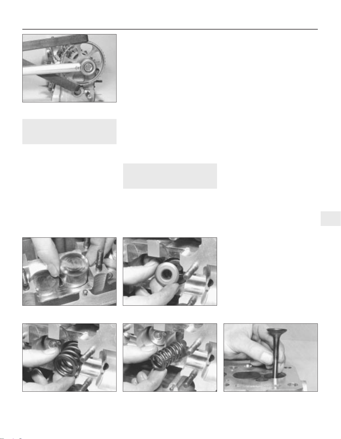
4 Camshaft - removal
3
1 Unscrew the nuts and bolts from the valve
cover and remove the cover together with the
gasket and reinforcement strips.
2 Turn the engine until the indentation in the
camshaft sprocket appears in the TDC hole in
the timing cover and the notch in the crankshaft
pulley is aligned with the TDC pointer on the
front of the oil pump. Now turn the crankshaft
one quarter of a turn anti-clockwise so that
none of the pistons are at TDC.
3 Unbolt and remove the timing cover, noting
that the dipstick tube and earth lead are fitted
to the upper bolts. On some later 1.3 litre
models, it is necessary to remove the
crankshaft pulley to remove the lower timing
belt cover.
4 Loosen the coolant pump retaining bolts,
then turn the pump body clockwise to release
the tension from the timing belt. Remove the
timing belt from the camshaft sprocket.
5 Devise a method to prevent the camshaft
turning and remove the sprocket bolt (see
illustration). Remove the camshaft sprocket
and where applicable, the Woodruff key.
6 The camshaft bearing caps must be refitted
in their original locations and the same way
round. They are usually numbered but mark
them if necessary, to ensure correct refitting.
7 Remove bearing caps Nos 5, 1 and 3, in
that order. Now undo the nuts holding 2 and 4
in a diagonal pattern and the camshaft will lift
them up as the pressure of the valve springs
is exerted. When they are free, lift the caps
off.
8 If the caps are stuck, give them a sharp tap
with a soft-faced mallet to loosen them. Do
not try to lever them off with a screwdriver.
9 Lift out the camshaft complete with the oil
seal.
5 Cylinder head - dismantling
and overhaul
3
Caution: If new tappets are fitted, the
engine must not be started after fitting for
approximately 30 minutes, or the valves
will strike the pistons.
Cylinder head
1 If the valve seats are badly pitted or eroded
they can be reworked but this is a specialist
job best left to a VW dealer or engine overhaul
specialist.
2 Similarly, if the head is warped, its surfaces
can be skimmed, again by specialist
engineers.
3 If it is found that there are cracks from the
valve seats or valve seat inserts to the spark
plug threads, the cylinder head may still be
serviceable. Consult your VW dealer for
advice.
Hydraulic bucket tappets
4 With the camshaft removed, lift out the
tappets one by one, ensuring that they are
kept in their correct order and can be returned
to their original bores (see illustration).
5 Place them, cam contact surface down, on
a clean sheet of paper as they are removed.
6 Inspect the tappets for wear (indicated by
ridging on the clean surface), pitting and
cracks.
7 Tappets cannot be repaired and if worn,
must be renewed.
8 Before fitting the tappets, lubricate all parts
liberally with clean engine oil and slip each
tappet back into its original bore.
Valves
9 With the camshaft and tappets removed,
use a valve spring compressor with a deep
reach to compress the valve springs. Remove
the two cotters and release the compressor
and springs.
10 Lift out the upper spring seat (see
illustration).
11 Remove the outer and inner valve springs
(see illustrations).
12 Lift out the valve (see illustration).
13 The valves should be inspected as
described in Part A of this Chapter, Section
11.
14 Valves must be renewed if they are worn
and be ground in the normal manner.
15 If possible, check the valve spring lengths
against new ones. Renew the whole set if any
are too short.
16 Refitting is a reversal of removal.
Valve stem oil seals
17 The valve stem oil seals should be
renewed whenever the valves are removed,
by prising them from the ends of the valve
guides (see illustration).
Engine repair procedures - 1.05 and 1.3 litre post August 1985 2B•3
2B
4.5 Two lengths of metal used to lock
camshaft sprocket
5.4 Removing an hydraulic bucket tappet 5.10 Removing valve spring upper seat
5.11a Removing an outer valve spring 5.11b Removing an inner valve spring 5.12 Removing a valve
1081 VW Golf & Jetta
Page 62
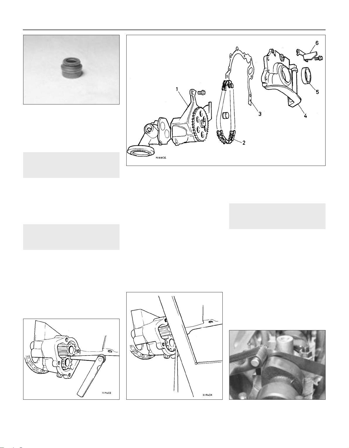
18 With the seals removed, the lower spring
seats can also be lifted out for cleaning. Press
the new seals onto the ends of the valve
guides.
6 Timing belt and sprockets -
removal
3
As from August 1986, the crankshaft
sprocket incorporates a lug for engagement
with the groove in the crankshaft, replacing
the Woodruff key arrangement described in
Part A if this Chapter.
When tightening the crankshaft sprocket
bolt, observe the specified stages.
7 Oil pump - removal and
examination
3
Note: The oil pump can be removed with the
engine still in the vehicle
1 Drain the engine oil.
2 Disconnect the exhaust downpipe and the
inboard end of the right-hand driveshaft to
permit sump removal.
3 Remove the sump.
4 If it is only desired to check backlash in the
pump gears, this can be done by removing
the cover and strainer assembly from the back
of the pump (see illustration).
5 Check backlash and axial play against the
specified tolerances (see illustrations).
6 If the tolerances are exceeded then the oil
pump must be renewed.
7 To remove the pump, first remove the
following components:
a) Camshaft drivebelt (timing belt)
b) Alternator drivebelt
c) Crankshaft pulley
d) Lower timing belt cover
e) Front cover and TDC setting bracket
8 If they are still in position, remove the bolts
holding the rear stay bracket.
9 Remove the two bolts holding the pump to
the cylinder block.
10 This will release the tension on the chain
and allow the pump to be removed.
11 If sufficient slack in the chain cannot be
achieved by this method, then slide the pump,
chain and crankshaft drive sprocket forward
together.
12 Check the chain and teeth of the drive
sprockets and renew any parts which are
worn.
13 If a new pump is being fitted, renew all
associated parts at the same time.
8 Camshaft - examination
3
1 Clean the camshaft in solvent, then inspect
its journals and cam peaks for pitting, scoring,
cracking and wear.
2 The camshaft bearings are machined
directly into the cylinder head and the bearing
caps.
3 Radial play in the bearings can be
measured using the Plastigage method.
Compare the results with the specified
dimension.
4 If wear is evident, consult your VW dealer.
5 To check camshaft endfloat, refit the
camshaft using only number 3 bearing cap.
6 Set up a dial test indicator or use feeler
blades to measure the endfloat (see
illustration). If the endfloat is greater than that
specified, consult your VW dealer.
2B•4 Engine repair procedures - 1.05 and 1.3 litre post August 1985
5.17 A valve stem oil seal
7.5a Checking oil pump backlash 7.5b Checking oil pump axial play 8.6 Measuring camshaft endfloat
1081 VW Golf & Jetta
7.4 Oil pump components
1 Oil pump
2 Chain
3 Gasket
4 Cover
5 Oil seal
6 TDC bracket
Page 63
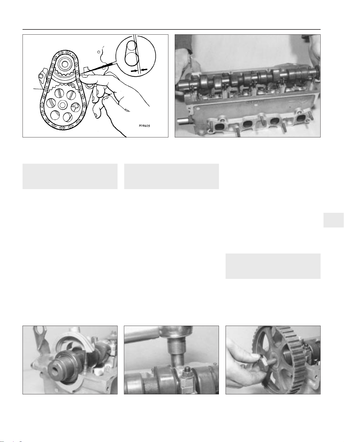
9 Oil pump - refitting
3
Refitting is a reversal of removal, but bear in
mind the following points:
a) Use new gaskets on all components.
b) Lubricate all new parts liberally with clean
engine oil.
c) If the small plug in the front cover is at all
damaged, renew it.
d) Fit a new crankshaft oil seal to the cover.
The oil seal can be prised out and a new
one pressed fully home.
e) The chain is tensioned by moving the
pump housing against its mounting bolts.
f) With light finger pressure exerted on the
chain, deflection should be as specified
(see illustration).
g) Whenever the sump is removed with the
engine in situ, the two hexagon screws in
the sealing flange at the flywheel end
should be replaced by socket-headed
screws and spring washers, and tightened
to the specified torque setting.
10 Camshaft - refitting
3
1 Lubricate the bucket tappets, the camshaft
journals and the camshaft liberally with clean
engine oil.
2 Place the camshaft in position on the
cylinder head (see illustration).
3 Fit a new camshaft oil seal (see
illustration).
4 Refit the bearing caps, ensuring that they
are the right way and in their correct position
(they should be numbered 1 to 5, readable
from the exhaust manifold side of the head).
5 Thread on the cap retaining nuts loosely,
then tighten the nuts on Nos. 2 and 4 caps in
a diagonal sequence to the Stage 1 torque
figure specified (see illustration).
6 Tighten the nuts on caps 1, 3 and 5 to the
Stage 1 torque.
7 Once all nuts have been tightened to the
Stage 1 torque, tighten all nuts a further 90°
(Stage 2). Fit and tighten No. 5 cap screws to
the correct torque.
8 Refit the Woodruff key into its slot in the
camshaft, where applicable. Fit the camshaft
sprocket and tighten the bolt to the specified
torque (see illustration).
9 If the work is being carried out in the engine
compartment, follow the procedure given in
Part A of this Chapter, Section 35, paragraphs
9 to 18.
10 Ignore any reference to the oil spray tube
and be sure to refit the oil shield at the
distributor end of the camshaft before the
valve cover is refitted.
11 If the cylinder head is out of the vehicle, it
will obviously have to be refitted before the
timing belt can be reconnected.
11 Cylinder head - refitting
3
1 Clean all traces of old gasket from the
cylinder block and cylinder head faces, taking
great care not to mark the gasket surfaces.
2 Using a new gasket, fit the inlet manifold
(see illustrations).
Engine repair procedures - 1.05 and 1.3 litre post August 1985 2B•5
2B
10.3 Camshaft oil seal 10.5 Tightening a camshaft bearing cap
nut
10.8 Fitting the camshaft sprocket bolt
1081 VW Golf & Jetta
9.1 Checking oil pump drive chain tension
10.2 Refitting the camshaft
Page 64
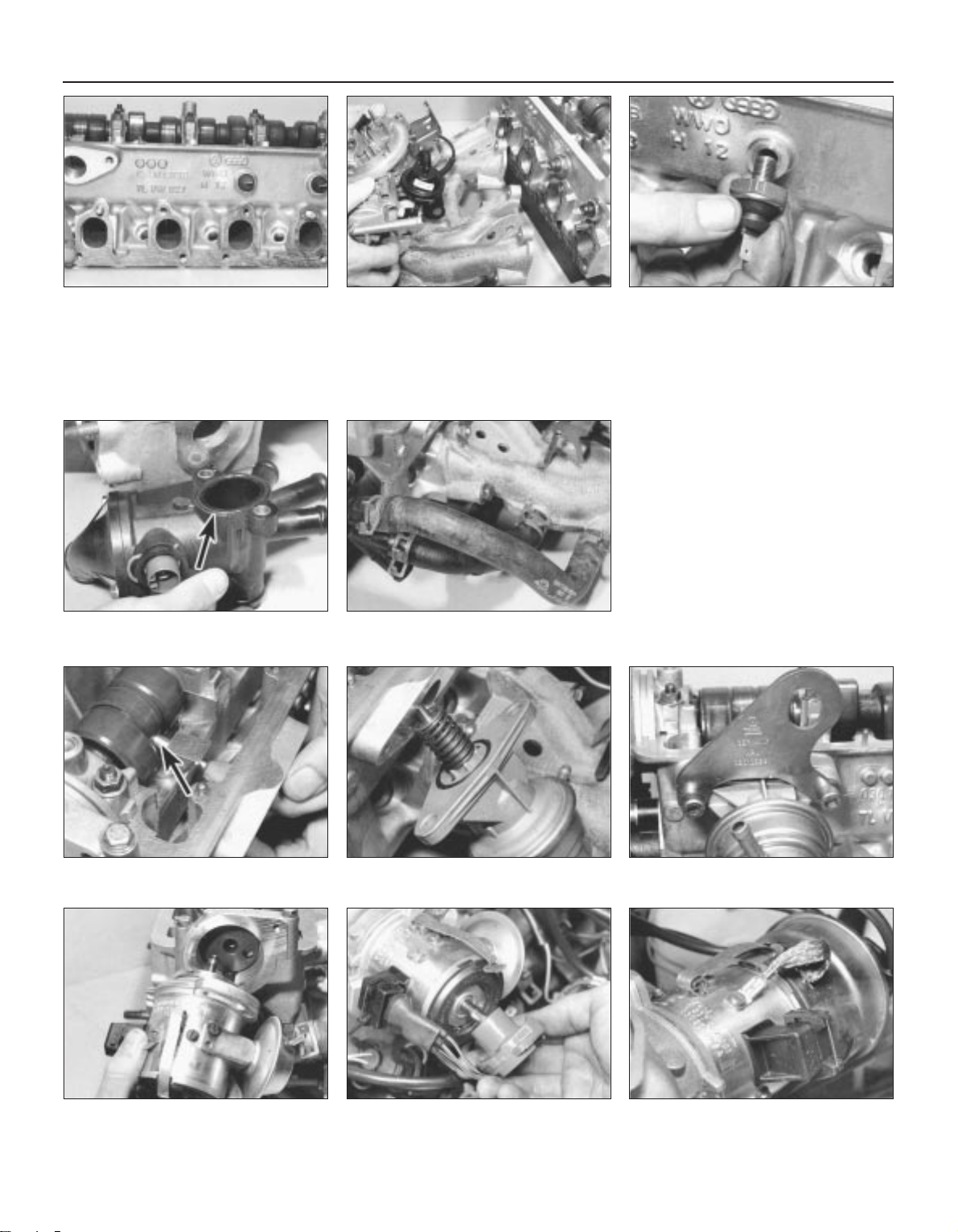
3 If they have been removed, refit the oil
pressure switches, using new copper sealing
washers (see illustration).
4 Refit the thermostat housing, using a new
O-ring (see illustration).
5 Refit the coolant hoses, ensuring that they
are connected up in the correct position (see
illustration).
6 Lubricate the fuel pump plunger with clean
engine oil and slip it into its housing in the
cylinder head (see illustration).
7 Refit the fuel pump and fit and tighten the
bolts, not forgetting the engine lifting eye (see
illustrations).
8 Slide the distributor into position and
ensure that it goes fully home (see
illustration). Hand-tighten the retaining bolts.
9 Fit the distributor rotor arm (see
illustration).
10 Fit the distributor cap and connect up the
earth lead (see illustration).
11 Check the timing marks on the cylinder
head and camshaft sprocket are lined up.
12 Note that none of the pistons should be at
TDC when refitting the cylinder head.
13 Position a new cylinder head gasket on
the cylinder block (see illustration).
14 Lower the cylinder head gently into
position. Special guides are used by the
manufacturer both to line up the gasket and
2B•6 Engine repair procedures - 1.05 and 1.3 litre post August 1985
11.2a Fitting a new inlet manifold gasket 11.2b Fitting inlet manifold complete with
carburettor
11.3 Refitting oil pressure switch
11.8 Refitting ignition distributor 11.9 Fitting rotor arm 11.10 Fitting distributor cap and earth lead
11.6 Fitting fuel pump plunger (arrowed) 11.7a Fitting fuel pump
11.4 O-ring (arrowed) in thermostat
housing
11.5 Coolant hoses in position
11.7b Location of engine lifting eye
1081 VW Golf & Jetta
Page 65
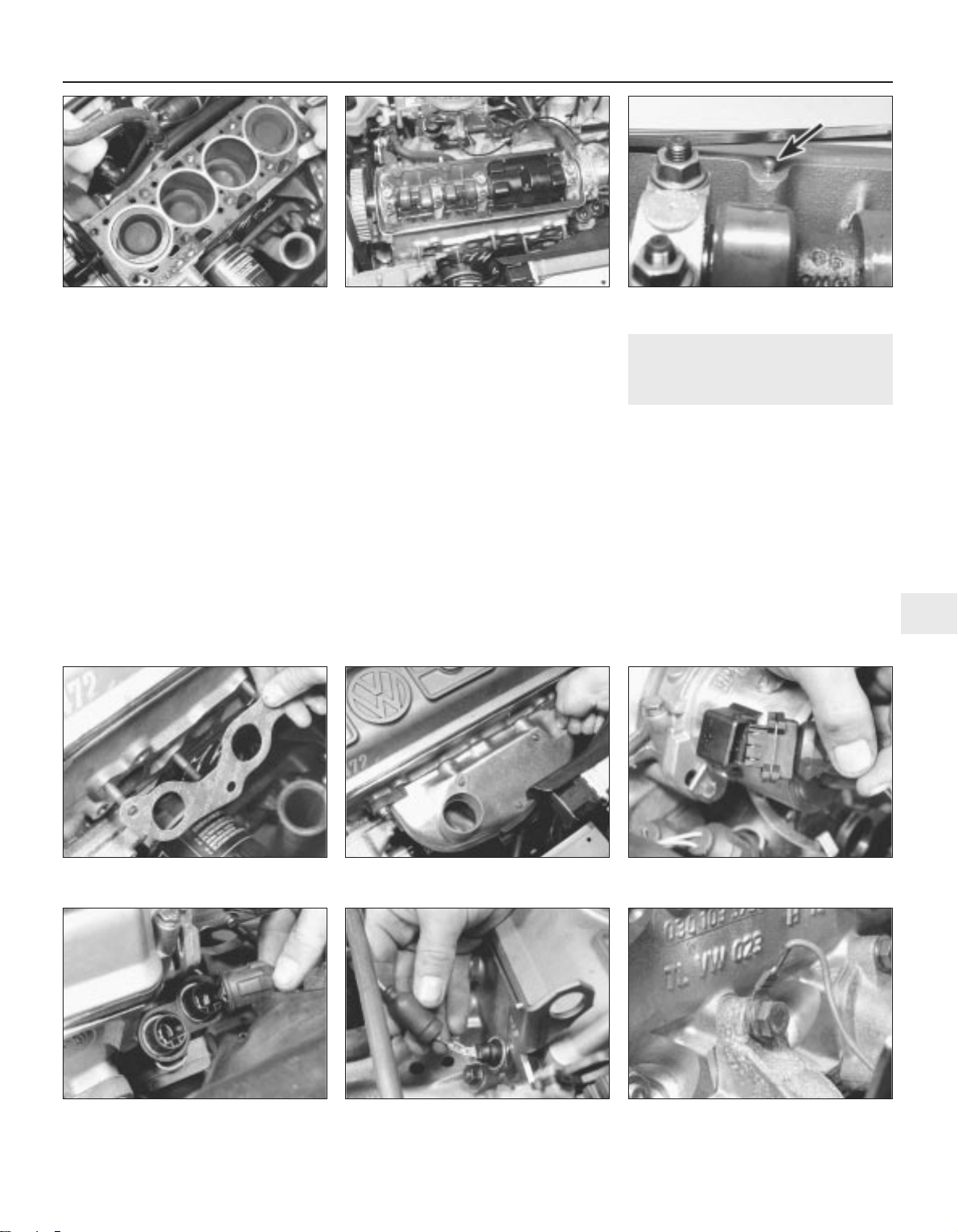
guide the cylinder head into position but this
can be done using suitable sized rods
inserted in two cylinder head bolt holes.
15 Install the cylinder head bolts. Refer to
Part A of this Chapter for the tightening
sequence but use the torque figures and
stages given in the Specifications of this
Chapter.
16 It is not necessary to retighten the bolts
after a period of service, as is normally the
case.
17 Refit the plastic oil shield (see
illustration).
18 Using a new rubber sealing gasket
properly located over the dowels, refit the
valve cover (see illustration).
19 Fit a new gasket to the exhaust manifold
(see illustration).
20 Fit the exhaust manifold, tightening its
nuts securely, then fit the hot air shroud (see
illustration).
21 Connect up the exhaust downpipe and
any other exhaust brackets loosened during
removal.
22 Refit all remaining hoses of the cooling
system and fuel system, referring to the
relevant Chapter where necessary.
23 Refit all electrical connections disturbed
during dismantling (distributor, carburettor, oil
pressure and coolant temperature switches,
inlet manifold preheater, etc.) (see
illustrations). Do not forget the earth lead
under the inlet manifold nut.
24 Refit the distributor vacuum hose.
25 With reference to Part A of this Chapter,
Section 37, refit the timing belt and covers.
26 Refit the throttle cable.
27 Refit the spark plugs, air cleaner and
associated pipework and electrical leads.
28 Check oil and coolant levels, replenishing
as necessary, then adjust the ignition timing.
12 Hydraulic bucket tappets -
checking free travel
2
1 Start the engine and run it until the radiator
cooling fan has switched on once.
2 Increase engine speed to about 2500 rpm
for about two minutes.
3 Irregular noises are normal when starting
but should become quiet after a few minutes
running.
4 If the valves are still noisy, carry out the
following check to identify worn tappets.
5 Stop the engine and remove the valve cover
from the cylinder head.
6 Turn the crankshaft clockwise by using a
wrench on the crankshaft pulley securing bolt,
until the cam of the tappet to be checked is
facing upward and is not exerting any
pressure on the tappet.
Engine repair procedures - 1.05 and 1.3 litre post August 1985 2B•7
2B
11.13 Cylinder head gasket in position 11.17 Plastic oil shield correctly located 11.18 Locating dowel for valve cover
gasket (arrowed)
11.23b Coolant temperature
switch/sender electrical connection
11.23c Oil pressure switch electrical
connection
11.23d Earth lead under inlet manifold bolt
head
11.19 Fitting a new exhaust manifold
gasket
11.20 Fitting hot air shroud 11.23a Ignition distributor electrical
connection
1081 VW Golf & Jetta
Page 66
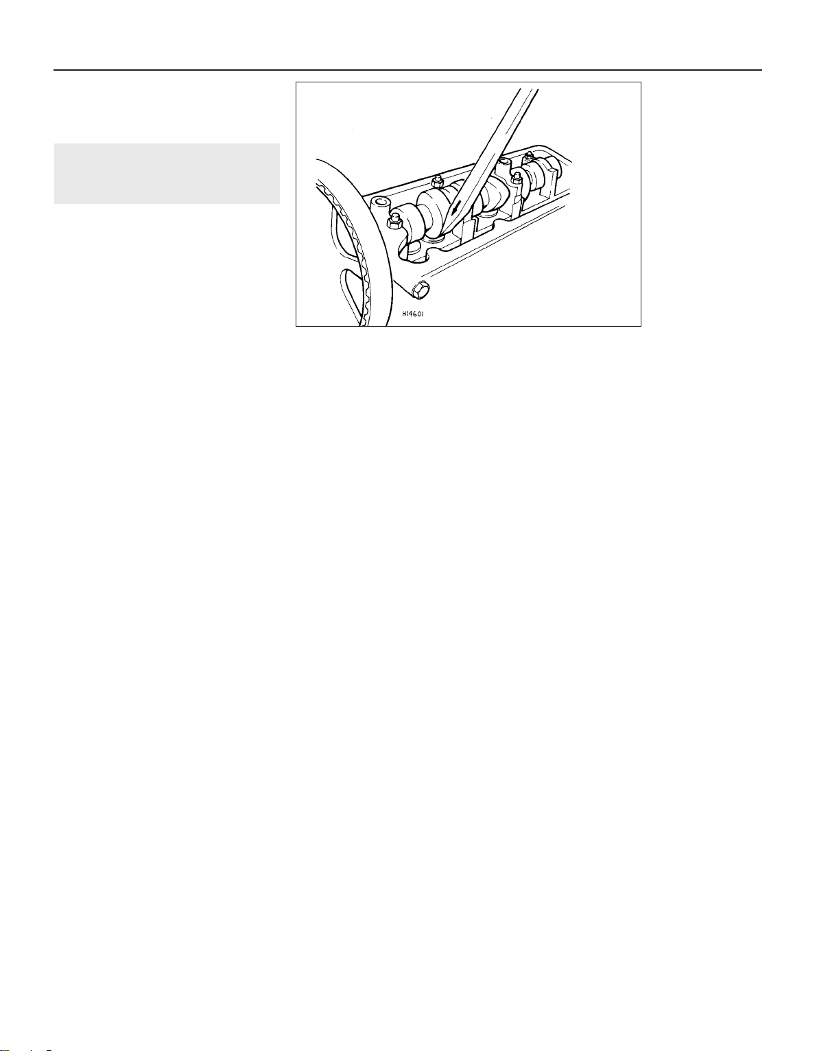
7 Press the tappet down using a wooden or
plastic wedge (see illustration).
8 If free travel of the tappet exceeds that
specified, the tappet must be renewed.
13 Engine - adjustments after
major overhaul
2
If the valve tappets have been renewed, it is
essential that no attempt to restart the engine
is made for a minimum period of 30 minutes
after installation. Failure to observe this
precaution may result in engine damage
caused by the valves contacting the pistons.
2B•8 Engine repair procedures - 1.05 and 1.3 litre post August 1985
12.7 Checking hydraulic tappet free travel
1081 VW Golf & Jetta
Page 67

1081 VW Golf & Jetta
2C
Chapter 2 Part C:
Engine repair pr ocedur es - 1.6 and 1.8 litr e 8 valve
General
Type . . . . . . . . . . . . . . . . . . . . . . . . . . . . . . . . . . . . . . . . . . . . . . . . . . . . Four-cylinder in-line, water cooled, overhead camshaft
Code:
1.6 litre:
Without catalytic converter . . . . . . . . . . . . . . . . . . . . . . . . . . . . . . . EZ
With catalytic converter . . . . . . . . . . . . . . . . . . . . . . . . . . . . . . . . . RF
1.8 litre:
Jetronic - fuel injection . . . . . . . . . . . . . . . . . . . . . . . . . . . . . . . . . . EV
Carburettor . . . . . . . . . . . . . . . . . . . . . . . . . . . . . . . . . . . . . . . . . . . GU
GTi - January 1987 on:
Without catalytic converter . . . . . . . . . . . . . . . . . . . . . . . . . . . . . PB, GU
With catalytic converter . . . . . . . . . . . . . . . . . . . . . . . . . . . . . . . . RH, RP, PF
Firing order . . . . . . . . . . . . . . . . . . . . . . . . . . . . . . . . . . . . . . . . . . . . . . . 1-3-4-2 (No 1 at camshaft sprocket end)
Displacement:
1.6 litre . . . . . . . . . . . . . . . . . . . . . . . . . . . . . . . . . . . . . . . . . . . . . . . . 1595 cc
1.8 litre . . . . . . . . . . . . . . . . . . . . . . . . . . . . . . . . . . . . . . . . . . . . . . . . 1781 cc
Bore:
1.6 litre . . . . . . . . . . . . . . . . . . . . . . . . . . . . . . . . . . . . . . . . . . . . . . . . 81.0 mm
1.8 litre . . . . . . . . . . . . . . . . . . . . . . . . . . . . . . . . . . . . . . . . . . . . . . . . 81.0 mm
Stroke:
1.6 litre . . . . . . . . . . . . . . . . . . . . . . . . . . . . . . . . . . . . . . . . . . . . . . . . 77.4 mm
1.8 litre . . . . . . . . . . . . . . . . . . . . . . . . . . . . . . . . . . . . . . . . . . . . . . . . 86.4 mm
Compression ratio:
1.6 litre . . . . . . . . . . . . . . . . . . . . . . . . . . . . . . . . . . . . . . . . . . . . . . . . 9.0 to 1
1.8 litre
Code RP . . . . . . . . . . . . . . . . . . . . . . . . . . . . . . . . . . . . . . . . . . . . . 9.0 to 1
All other codes . . . . . . . . . . . . . . . . . . . . . . . . . . . . . . . . . . . . . . . . 10.0 to 1
Camshaft - removal, examination and refitting . . . . . . . . . . . . . . . . . 10
Crankshaft and bearings - examination and renovation . . . . . . . . . . 22
Crankshaft and main bearings - refitting . . . . . . . . . . . . . . . . . . . . . . 30
Crankshaft and main bearings - removal . . . . . . . . . . . . . . . . . . . . .15
Cylinder block/crankcase - examination and renovation . . . . . . . . . 23
Cylinder head - dismantling and overhaul . . . . . . . . . . . . . . . . . . . . . 12
Cylinder head - refitting . . . . . . . . . . . . . . . . . . . . . . . . . . . . . . . . . . . 34
Cylinder head - removal . . . . . . . . . . . . . . . . . . . . . . . . . . . . . . . . . .11
Engine - adjustments after major overhaul . . . . . . . . . . . . . . . . . . . . 39
Engine - refitting . . . . . . . . . . . . . . . . . . . . . . . . . . . . . . . . . . . . . . . . 37
Engine - removal . . . . . . . . . . . . . . . . . . . . . . . . . . . . . . . . . . . . . . . . 5
Engine ancillary components - removal . . . . . . . . . . . . . . . . . . . . . . 8
Engine ancillary components refitting . . . . . . . . . . . . . . . . . . . . . . . . 36
Engine dismantling - general information . . . . . . . . . . . . . . . . . . . . . 7
Engine reassembly - general information . . . . . . . . . . . . . . . . . . . . . 29
Engine/gearbox - separation and reconnection . . . . . . . . . . . . . . . . 6
Examination and renovation - general information . . . . . . . . . . . . . . 21
Flywheel/driveplate - examination and renovation . . . . . . . . . . . . . . 27
General information . . . . . . . . . . . . . . . . . . . . . . . . . . . . . . . . . . . . . . 1
Hydraulic bucket tappets - checking free travel (from August 1985) . . 38
Intermediate shaft - examination and renovation . . . . . . . . . . . . . . . 26
Intermediate shaft - refitting . . . . . . . . . . . . . . . . . . . . . . . . . . . . . . . 31
Intermediate shaft - removal . . . . . . . . . . . . . . . . . . . . . . . . . . . . . . . 16
Major operations only possible after removal of engine from vehicle . . 3
Major operations possible with engine in vehicle . . . . . . . . . . . . . . . 2
Method of engine removal . . . . . . . . . . . . . . . . . . . . . . . . . . . . . . . . . 4
Oil cooler - removal and refitting . . . . . . . . . . . . . . . . . . . . . . . . . . . . 18
Oil filter - renewal . . . . . . . . . . . . . . . . . . . . . . . . . . . . . . . . . . . . . . . . 17
Oil filter mounting - removal and refitting . . . . . . . . . . . . . . . . . . . . . 19
Oil pump - examination and renovation . . . . . . . . . . . . . . . . . . . . . . 25
Oil seals - renewal . . . . . . . . . . . . . . . . . . . . . . . . . . . . . . . . . . . . . . . 20
Pistons and connecting rods - examination and renovation . . . . . . . 24
Pistons and connecting rods - refitting . . . . . . . . . . . . . . . . . . . . . . . 32
Pistons and connecting rods - removal . . . . . . . . . . . . . . . . . . . . . . . 14
Sump and oil pump - removal and refitting . . . . . . . . . . . . . . . . . . . . 13
Timing belt and sprockets - examination and renovation . . . . . . . . . 28
Timing belt and sprockets - refitting . . . . . . . . . . . . . . . . . . . . . . . . . 35
Timing belt and sprockets - removal . . . . . . . . . . . . . . . . . . . . . . . . . 9
Valve clearances - checking and adjustment (pre August 1985) . . .33
2C•1
Specifications
Contents
Easy, suitable for
novice with little
experience
Fairly easy, suitable
for beginner with
some experience
Fairly difficult,
suitable for competent
DIY mechanic
Difficult, suitable for
experienced DIY
mechanic
Very difficult,
suitable for expert DIY
or professional
Degrees of difficulty
5
4
3
2
1
Page 68

Compression pressure:
1.6 litre:
New . . . . . . . . . . . . . . . . . . . . . . . . . . . . . . . . . . . . . . . . . . . . . . . . . 9 to 12 bar
Minimum . . . . . . . . . . . . . . . . . . . . . . . . . . . . . . . . . . . . . . . . . . . . . 7.5 bar
Maximum permissible difference between any two cylinders . . . . 3.0 bar
1.8 litre:
New . . . . . . . . . . . . . . . . . . . . . . . . . . . . . . . . . . . . . . . . . . . . . . . . . 10 to 13 bar
Minimum . . . . . . . . . . . . . . . . . . . . . . . . . . . . . . . . . . . . . . . . . . . . . 7.5 bar
Maximum permissible difference between any two cylinders . . . . 3.0 bar
Crankshaft
Main journal:
Standard diameter . . . . . . . . . . . . . . . . . . . . . . . . . . . . . . . . . . . . . . . 54.0 mm
Undersizes . . . . . . . . . . . . . . . . . . . . . . . . . . . . . . . . . . . . . . . . . . . . . 53.75, 53.50 and 53.25 mm
Crankpin:
Standard diameter . . . . . . . . . . . . . . . . . . . . . . . . . . . . . . . . . . . . . . . 47.80 mm
Journal undersizes . . . . . . . . . . . . . . . . . . . . . . . . . . . . . . . . . . . . . . . 47.55, 47.30 and 47.05 mm
Endfloat:
Maximum . . . . . . . . . . . . . . . . . . . . . . . . . . . . . . . . . . . . . . . . . . . . . . 0.25 mm
Minimum . . . . . . . . . . . . . . . . . . . . . . . . . . . . . . . . . . . . . . . . . . . . . . . 0.07 mm
Main bearing maximum running clearance . . . . . . . . . . . . . . . . . . . . . . 0.17 mm
Connecting rods
Big-end:
Maximum running clearance . . . . . . . . . . . . . . . . . . . . . . . . . . . . . . . . 0.012 mm
Maximum endfloat . . . . . . . . . . . . . . . . . . . . . . . . . . . . . . . . . . . . . . . 0.37 mm
Pistons
Clearance in bore:
Maximum . . . . . . . . . . . . . . . . . . . . . . . . . . . . . . . . . . . . . . . . . . . . . . 0.07 mm
Minimum . . . . . . . . . . . . . . . . . . . . . . . . . . . . . . . . . . . . . . . . . . . . . . . 0.03 mm
Diameter:
Standard . . . . . . . . . . . . . . . . . . . . . . . . . . . . . . . . . . . . . . . . . . . . . . . 80.98 mm
Oversize:
1st oversize . . . . . . . . . . . . . . . . . . . . . . . . . . . . . . . . . . . . . . . . . . . 81.23 mm
2nd oversize . . . . . . . . . . . . . . . . . . . . . . . . . . . . . . . . . . . . . . . . . . 81.48 mm
Wear limit (10 mm from base/ right angles to pin) . . . . . . . . . . . . . . . . . 0.04 mm
Piston rings
Maximum clearance in groove . . . . . . . . . . . . . . . . . . . . . . . . . . . . . . . . 0.15 mm
End gap:
Compression rings . . . . . . . . . . . . . . . . . . . . . . . . . . . . . . . . . . . . . . . 0.30 to 0.45 mm
Oil scraper ring:
1 part . . . . . . . . . . . . . . . . . . . . . . . . . . . . . . . . . . . . . . . . . . . . . . . . 0.25 to 0.40 mm
2 part . . . . . . . . . . . . . . . . . . . . . . . . . . . . . . . . . . . . . . . . . . . . . . . . 0.25 to 0.45 mm
3 part . . . . . . . . . . . . . . . . . . . . . . . . . . . . . . . . . . . . . . . . . . . . . . . . 0.25 to 0.50 mm
Maximum end gap . . . . . . . . . . . . . . . . . . . . . . . . . . . . . . . . . . . . . . . . . 1.0 mm
Gudgeon pin
Fit in piston . . . . . . . . . . . . . . . . . . . . . . . . . . . . . . . . . . . . . . . . . . . . . . . Push fit at 60°C
Intermediate shaft
Maximum endfloat . . . . . . . . . . . . . . . . . . . . . . . . . . . . . . . . . . . . . . . . . 0.25 mm
Cylinder head
Maximum allowable face distortion . . . . . . . . . . . . . . . . . . . . . . . . . . . . 0.1 mm
Minimum height . . . . . . . . . . . . . . . . . . . . . . . . . . . . . . . . . . . . . . . . . . . 132.6 mm
Camshaft
Run-out at centre bearing . . . . . . . . . . . . . . . . . . . . . . . . . . . . . . . . . . . . 0.01 mm
Endfloat . . . . . . . . . . . . . . . . . . . . . . . . . . . . . . . . . . . . . . . . . . . . . . . . . . 0.15 mm
Valves
Seat angle . . . . . . . . . . . . . . . . . . . . . . . . . . . . . . . . . . . . . . . . . . . . . . . . 45°
Head diameter:
Inlet:
Codes PB, PF . . . . . . . . . . . . . . . . . . . . . . . . . . . . . . . . . . . . . . . . . 40.0 mm
All other codes . . . . . . . . . . . . . . . . . . . . . . . . . . . . . . . . . . . . . . . . 38.0 mm
Exhaust . . . . . . . . . . . . . . . . . . . . . . . . . . . . . . . . . . . . . . . . . . . . . . . . 33.0 mm
2C•2 Engine repair procedures - 1.6 and 1.8 litre 8 valve
1081 VW Golf & Jetta
Page 69

Stem diameter:
Inlet . . . . . . . . . . . . . . . . . . . . . . . . . . . . . . . . . . . . . . . . . . . . . . . . . . . 7.97 mm
Exhaust . . . . . . . . . . . . . . . . . . . . . . . . . . . . . . . . . . . . . . . . . . . . . . . . 7.95 mm
Standard overall length*:
Inlet:
Codes EZ, EV, GU . . . . . . . . . . . . . . . . . . . . . . . . . . . . . . . . . . . . . . 98.70 mm
All other codes . . . . . . . . . . . . . . . . . . . . . . . . . . . . . . . . . . . . . . . . 91.0 mm
Exhaust:
Codes EZ, EV, GU . . . . . . . . . . . . . . . . . . . . . . . . . . . . . . . . . . . . . . 98.50 mm
Codes PB, PF, RP . . . . . . . . . . . . . . . . . . . . . . . . . . . . . . . . . . . . . . 90.95 mm
All other codes . . . . . . . . . . . . . . . . . . . . . . . . . . . . . . . . . . . . . . . . 90.80 mm
* Caution:
Check with manufacturer on valve dimensions before renewing
Valve guides
Maximum valve rock (stem flush with guide):
Inlet . . . . . . . . . . . . . . . . . . . . . . . . . . . . . . . . . . . . . . . . . . . . . . . . . . . 1.0 mm
Exhaust . . . . . . . . . . . . . . . . . . . . . . . . . . . . . . . . . . . . . . . . . . . . . . . . 1.3 mm
Hydraulic tappets
Maximum free travel . . . . . . . . . . . . . . . . . . . . . . . . . . . . . . . . . . . . . . . . 0.1 mm
Valve timing
Nil valve clearance at 1.0 mm valve lift
1.6 litre (code EZ - shim bucket tappets):
Inlet opens . . . . . . . . . . . . . . . . . . . . . . . . . . . . . . . . . . . . . . . . . . . . . 5° BTDC
Inlet closes . . . . . . . . . . . . . . . . . . . . . . . . . . . . . . . . . . . . . . . . . . . . . 21° ABDC
Exhaust opens . . . . . . . . . . . . . . . . . . . . . . . . . . . . . . . . . . . . . . . . . . 41° BBDC
Exhaust closes . . . . . . . . . . . . . . . . . . . . . . . . . . . . . . . . . . . . . . . . . . 3° BTDC
1.6 litre (code EZ - hydraulic tappets - August 1985 to March 1986):
Inlet opens . . . . . . . . . . . . . . . . . . . . . . . . . . . . . . . . . . . . . . . . . . . . . 3° BTDC
Inlet closes . . . . . . . . . . . . . . . . . . . . . . . . . . . . . . . . . . . . . . . . . . . . . 19° ABDC
Exhaust opens . . . . . . . . . . . . . . . . . . . . . . . . . . . . . . . . . . . . . . . . . . 27° BBDC
Exhaust closes . . . . . . . . . . . . . . . . . . . . . . . . . . . . . . . . . . . . . . . . . . 5° BTDC
1.6 litre (code EZ - hydraulic tappets - March 1986 on):
Inlet opens . . . . . . . . . . . . . . . . . . . . . . . . . . . . . . . . . . . . . . . . . . . . . TDC
Inlet closes . . . . . . . . . . . . . . . . . . . . . . . . . . . . . . . . . . . . . . . . . . . . . 22° ABDC
Exhaust opens . . . . . . . . . . . . . . . . . . . . . . . . . . . . . . . . . . . . . . . . . . 28° BBDC
Exhaust closes . . . . . . . . . . . . . . . . . . . . . . . . . . . . . . . . . . . . . . . . . . 6° BTDC
1.6 litre (code RF):
Inlet opens . . . . . . . . . . . . . . . . . . . . . . . . . . . . . . . . . . . . . . . . . . . . . TDC
Inlet closes . . . . . . . . . . . . . . . . . . . . . . . . . . . . . . . . . . . . . . . . . . . . . 22° ABDC
Exhaust opens . . . . . . . . . . . . . . . . . . . . . . . . . . . . . . . . . . . . . . . . . . 28° BBDC
Exhaust closes . . . . . . . . . . . . . . . . . . . . . . . . . . . . . . . . . . . . . . . . . . 6° BTDC
1.8 litre (code GU - shim bucket tappets)
Inlet opens . . . . . . . . . . . . . . . . . . . . . . . . . . . . . . . . . . . . . . . . . . . . . 1° BTDC
Inlet closes . . . . . . . . . . . . . . . . . . . . . . . . . . . . . . . . . . . . . . . . . . . . . 37° ABDC
Exhaust opens . . . . . . . . . . . . . . . . . . . . . . . . . . . . . . . . . . . . . . . . . . 42° BBDC
Exhaust closes . . . . . . . . . . . . . . . . . . . . . . . . . . . . . . . . . . . . . . . . . . 2° ATDC
1.8 litre (code GU - hydraulic tappets - August 1985 to March 1986
Inlet opens . . . . . . . . . . . . . . . . . . . . . . . . . . . . . . . . . . . . . . . . . . . . . 3° BTDC
Inlet closes . . . . . . . . . . . . . . . . . . . . . . . . . . . . . . . . . . . . . . . . . . . . . 33° ABDC
Exhaust opens . . . . . . . . . . . . . . . . . . . . . . . . . . . . . . . . . . . . . . . . . . 41° BBDC
Exhaust closes . . . . . . . . . . . . . . . . . . . . . . . . . . . . . . . . . . . . . . . . . . 5° BTDC
1.8 litre (code GU - hydraulic tappets - March 1986 on):
Inlet opens . . . . . . . . . . . . . . . . . . . . . . . . . . . . . . . . . . . . . . . . . . . . . 2° BTDC
Inlet closes . . . . . . . . . . . . . . . . . . . . . . . . . . . . . . . . . . . . . . . . . . . . . 34° ABDC
Exhaust opens . . . . . . . . . . . . . . . . . . . . . . . . . . . . . . . . . . . . . . . . . . 44° BBDC
Exhaust closes . . . . . . . . . . . . . . . . . . . . . . . . . . . . . . . . . . . . . . . . . . 8° BTDC
1.8 litre (code EV):
Inlet opens . . . . . . . . . . . . . . . . . . . . . . . . . . . . . . . . . . . . . . . . . . . . . 2° BTDC
Inlet closes . . . . . . . . . . . . . . . . . . . . . . . . . . . . . . . . . . . . . . . . . . . . . 45° ABDC
Exhaust opens . . . . . . . . . . . . . . . . . . . . . . . . . . . . . . . . . . . . . . . . . . 45° BBDC
Exhaust closes . . . . . . . . . . . . . . . . . . . . . . . . . . . . . . . . . . . . . . . . . . 8° BTDC
1.8 litre (codes PB, PF):
Inlet opens . . . . . . . . . . . . . . . . . . . . . . . . . . . . . . . . . . . . . . . . . . . . . 3° ATDC
Inlet closes . . . . . . . . . . . . . . . . . . . . . . . . . . . . . . . . . . . . . . . . . . . . . 43° ABDC
Exhaust opens . . . . . . . . . . . . . . . . . . . . . . . . . . . . . . . . . . . . . . . . . . 37° BBDC
Exhaust closes . . . . . . . . . . . . . . . . . . . . . . . . . . . . . . . . . . . . . . . . . . 3° ATDC
Engine repair procedures - 1.6 and 1.8 litre 8 valve 2C•3
2C
1081 VW Golf & Jetta
Page 70

Valve timing (continued)
Nil valve clearance at 1.0 mm valve lift
1.8 litre (code RH):
Inlet opens . . . . . . . . . . . . . . . . . . . . . . . . . . . . . . . . . . . . . . . . . . . . . 2° BTDC
Inlet closes . . . . . . . . . . . . . . . . . . . . . . . . . . . . . . . . . . . . . . . . . . . . . 34° ABDC
Exhaust opens . . . . . . . . . . . . . . . . . . . . . . . . . . . . . . . . . . . . . . . . . . 44° BBDC
Exhaust closes . . . . . . . . . . . . . . . . . . . . . . . . . . . . . . . . . . . . . . . . . . 8° BTDC
1.8 litre (code RP - pre July 1988):
Inlet opens . . . . . . . . . . . . . . . . . . . . . . . . . . . . . . . . . . . . . . . . . . . . . 2° ATDC
Inlet closes . . . . . . . . . . . . . . . . . . . . . . . . . . . . . . . . . . . . . . . . . . . . . 38° ABDC
Exhaust opens . . . . . . . . . . . . . . . . . . . . . . . . . . . . . . . . . . . . . . . . . . 40° BBDC
Exhaust closes . . . . . . . . . . . . . . . . . . . . . . . . . . . . . . . . . . . . . . . . . . 4° BTDC
1.8 litre (code RP - August 1988 on):
Inlet opens . . . . . . . . . . . . . . . . . . . . . . . . . . . . . . . . . . . . . . . . . . . . . 5° BTDC
Inlet closes . . . . . . . . . . . . . . . . . . . . . . . . . . . . . . . . . . . . . . . . . . . . . 41° ABDC
Exhaust opens . . . . . . . . . . . . . . . . . . . . . . . . . . . . . . . . . . . . . . . . . . 37° BBDC
Exhaust closes . . . . . . . . . . . . . . . . . . . . . . . . . . . . . . . . . . . . . . . . . . 1° BTDC
Valve clearances
Warm:
Inlet . . . . . . . . . . . . . . . . . . . . . . . . . . . . . . . . . . . . . . . . . . . . . . . . . . . 0.20 to 0.30 mm
Exhaust . . . . . . . . . . . . . . . . . . . . . . . . . . . . . . . . . . . . . . . . . . . . . . . . 0.40 to 0.50 m
Cold:
Inlet . . . . . . . . . . . . . . . . . . . . . . . . . . . . . . . . . . . . . . . . . . . . . . . . . . . 0.15 to 0.25 mm
Exhaust . . . . . . . . . . . . . . . . . . . . . . . . . . . . . . . . . . . . . . . . . . . . . . . . 0.35 to 0.45 mm
Lubrication
System type . . . . . . . . . . . . . . . . . . . . . . . . . . . . . . . . . . . . . . . . . . . . . . Wet sump, pressure feed, full flow filter
Lubricant type/specification/capacity . . . . . . . . . . . . . . . . . . . . . . . . . . Refer to “Lubricants, fluids and capacities”
Filter type . . . . . . . . . . . . . . . . . . . . . . . . . . . . . . . . . . . . . . . . . . . . . . . . Champion C101/C160
Pump type . . . . . . . . . . . . . . . . . . . . . . . . . . . . . . . . . . . . . . . . . . . . . . . Twin gear, driven by intermediate shaft together with distributor
Pressure (2000 rpm with oil temperature 80°C) . . . . . . . . . . . . . . . . . . . 2.0 bar minimum
Torque wrench settings Nm lbf ft
Engine to gearbox:
M10 . . . . . . . . . . . . . . . . . . . . . . . . . . . . . . . . . . . . . . . . . . . . . . . . . . . 45 33
M12 . . . . . . . . . . . . . . . . . . . . . . . . . . . . . . . . . . . . . . . . . . . . . . . . . . . 75 55
Exhaust manifold nuts . . . . . . . . . . . . . . . . . . . . . . . . . . . . . . . . . . . . . . 25 18
Exhaust pipe to manifold . . . . . . . . . . . . . . . . . . . . . . . . . . . . . . . . . . . . 10 7
Flywheel/driveplate bolts . . . . . . . . . . . . . . . . . . . . . . . . . . . . . . . . . . . . 20 15
Clutch pressure plate/washer bolts (renew) . . . . . . . . . . . . . . . . . . . . . . 100 74
Sump bolts . . . . . . . . . . . . . . . . . . . . . . . . . . . . . . . . . . . . . . . . . . . . . . . 20 15
Sump drain plug . . . . . . . . . . . . . . . . . . . . . . . . . . . . . . . . . . . . . . . . . . . 30 22
Main bearing cap bolts . . . . . . . . . . . . . . . . . . . . . . . . . . . . . . . . . . . . . . 65 48
Connecting rod big-end cap nuts:
Stage 1 . . . . . . . . . . . . . . . . . . . . . . . . . . . . . . . . . . . . . . . . . . . . . . . . 30 22
Stage 2* . . . . . . . . . . . . . . . . . . . . . . . . . . . . . . . . . . . . . . . . . . . . . . . Further tighten 1/4 turn (90°)
Oil pump bolts . . . . . . . . . . . . . . . . . . . . . . . . . . . . . . . . . . . . . . . . . . . . 10 7
Oil pressure switch . . . . . . . . . . . . . . . . . . . . . . . . . . . . . . . . . . . . . . . . . 25 18
Oil filter flange bolts . . . . . . . . . . . . . . . . . . . . . . . . . . . . . . . . . . . . . . . . 25 18
Front seal flange bolts: . . . . . . . . . . . . . . . . . . . . . . . . . . . . . . . . . . . . . .
Small . . . . . . . . . . . . . . . . . . . . . . . . . . . . . . . . . . . . . . . . . . . . . . . . . . 20 15
Large . . . . . . . . . . . . . . . . . . . . . . . . . . . . . . . . . . . . . . . . . . . . . . . . . . 10 7
Intermediate shaft flange bolts . . . . . . . . . . . . . . . . . . . . . . . . . . . . . . . . 25 18
Camshaft bearing cap nuts (in sequence) . . . . . . . . . . . . . . . . . . . . . . . 20 15
Camshaft sprocket bolt . . . . . . . . . . . . . . . . . . . . . . . . . . . . . . . . . . . . . 80 59
Valve cover nuts . . . . . . . . . . . . . . . . . . . . . . . . . . . . . . . . . . . . . . . . . . . 10 7
Belt tensioner pulley . . . . . . . . . . . . . . . . . . . . . . . . . . . . . . . . . . . . . . . . 45 33
Crankshaft sprocket bolt (oiled) . . . . . . . . . . . . . . . . . . . . . . . . . . . . . . . 200 148
Intermediate shaft sprocket bolt . . . . . . . . . . . . . . . . . . . . . . . . . . . . . . . 80 59
V-belt pulley . . . . . . . . . . . . . . . . . . . . . . . . . . . . . . . . . . . . . . . . . . . . . . 20 15
Timing cover . . . . . . . . . . . . . . . . . . . . . . . . . . . . . . . . . . . . . . . . . . . . . . 10 7
Rear cover lower bolts . . . . . . . . . . . . . . . . . . . . . . . . . . . . . . . . . . . . . . 30 22
Rear cover top bolt . . . . . . . . . . . . . . . . . . . . . . . . . . . . . . . . . . . . . . . . . 10 7
Coolant pump bolts . . . . . . . . . . . . . . . . . . . . . . . . . . . . . . . . . . . . . . . . 20 15
Fuel pump bolts . . . . . . . . . . . . . . . . . . . . . . . . . . . . . . . . . . . . . . . . . . . 20 15
Distributor clamp bolt . . . . . . . . . . . . . . . . . . . . . . . . . . . . . . . . . . . . . . . 25 18
2C•4 Engine repair procedures - 1.6 and 1.8 litre 8 valve
1081 VW Golf & Jetta
Page 71

1 General information
The 1.6 and 1.8 litre 8-valve engines are of
four-cylinder, in-line, overhead camshaft
design, mounted transversely at the front of
the vehicle. The transmission is attached to
the flywheel end of the engine.
The crankshaft is of five main bearing type,
its endfloat being controlled by a shouldered
centre bearing or by half thrustwashers
located each side of the centre bearing.
The camshaft is driven by a toothed belt
which is tensioned by a tensioner on an
eccentric bearing. On engines manufactured
before August 1985, the valves are operated
by bucket type cam followers in direct contact
with the camshaft. From August 1985, all
engines are fitted with a redesigned cylinder
head incorporating hydraulic bucket tappets
in place of the previous shim bucket tappets.
Camshaft bearing No. 4 is deleted on all
single camshaft engines. In order to identify
the type of tappets fitted, a sticker is normally
affixed to the valve cover indicating that valve
clearance adjustment is neither necessary nor
possible.
An intermediate shaft (driven by the toothed
timing belt) drives the distributor and oil pump
and on carburettor equipped engines, the fuel
pump.
The oil pump is of twin gear type, driven
from the immediate shaft and incorporates a
pressure relief valve.
The aluminium cylinder head is of
conventional design with the inlet and exhaust
manifolds mounted on the rear side (as
viewed with the engine in the vehicle).
The crankcase ventilation system
comprises a hose from the flywheel end of the
valve cover to the side of the air cleaner.
On fuel injection equipped engines, there is
a hose to the air inlet manifold and a hose to
the air cleaner from a three-way connector on
the valve cover.
2 Major operations possible
with engine in vehicle
The following operations can be carried out
without having to remove the engine from the
vehicle:
a) Removal and servicing of the cylinder
head, camshaft and timing belt
b) Renewal of the crankshaft rear oil seal
(after removal of the transmission,
driveplate or clutch as applicable)
c) Removal of the sump and oil pump
d) Removal of the piston/connecting rod
assemblies (after removal of the cylinder
head and sump)
e) Renewal of the crankshaft front oil seal,
intermediate shaft front oil seal and
camshaft front oil seal
f) Renewal of the engine mountings
3 Major operations only
possible after removal of
engine from vehicle
The following operations can only be
carried out after removal of the engine from
the vehicle:
a) Renewal of crankshaft main bearings
b) Removal and refitting of the crankshaft
c) Removal and refitting of the intermediate
shaft
4 Method of engine removal
1 The engine, together with the gearbox,
must be lifted from the engine compartment,
then the engine separated from the gearbox
on the bench. Two people will be needed.
2 A hoist of 150 kg capacity will be needed to
lift the engine approximately 1 metre. If the
hoist is not portable and the engine is lifted,
then sufficient room must be left behind the
vehicle to push it back out of the way so that
the engine may be lowered. Blocks will be
needed to support the engine after removal .
3 Ideally, the vehicle should be over a pit. If
this is not possible then the body must be
supported on axle stands (see “Jacking and
vehicle support”) so that the front wheels may
be turned to undo the driveshaft nuts. The
left-hand shaft is accessible from above but
the right-hand shaft must be undone from
underneath. Removal of the gearshift linkage
can only be done from underneath, as can
exhaust downpipe-to-manifold detachment.
4 The exhaust downpipe-to-manifold flange
connection is secured by special spring clips
rather than bolts or studs and nuts. When
disconnecting and reconnecting the joint, it
will be necessary to use VW tool no. 3049A.
Without this tool, detachment and certainly
reconnection of the joint and clips is virtually
impossible, so make arrangements to borrow
or hire the tool in advance.
5 The only other special tools required will be
a set of splined key wrenches which will be
needed to remove and refit the socket-head
bolts used to secure certain items such as the
cylinder head bolts.
6 Draining of oil and coolant is best done
away from the working area if possible. This
saves the mess made by spilled oil in the
place where you must work.
7 Although not listed as an optional fitting on
UK models, an air conditioning system may
have been fitted. Where this is the case, the
following precautions must be taken when
handling refrigerant lines or system
components:
a) Do not stress or bend flexible hose lines
to a radius of less than 101 mm
b) Flexible hose lines must be correctly
located, must not chafe against adjacent
components and must be kept well clear
of the exhaust manifold and downpipe
c) All metal tubing lines must be kept free of
kinks and must be handled with care
d) Do not disconnect any of the air
conditioning supply lines
e) Do not weld or apply heat in the vicinity of
the air conditioning lines or equipment
f) If any part of the system is to be detached
then it must first be depressurised by your
VW dealer or a competent air conditioning
systems engineer. The only exception is
the removal and fitting of the compressor
drivebelt which can be achieved in the
same manner as for the alternator
drivebelt
5 Engine - removal
4
Carburettor equipped
1 Disconnect the battery negative lead.
2 Remove the bonnet.
3 Drain the engine coolant.
4 Position a suitable container beneath the
engine, undo the sump drain plug and drain the
engine oil - see Chapter 1. On completion clean
the drain plug and refit it. Renew the O-ring.
Engine repair procedures - 1.6 and 1.8 litre 8 valve 2C•5
2C
1081 VW Golf & Jetta
Cylinder head bolts (engine cold) . . . . . . . . . . . . . . . . . . . . . . . . . . . . . . As for 1.05 and 1.3 litre engines
Refer to illustration 5.25b. Also 40.1a and 40.1b in Part A of this Chapter.
a) M8 . . . . . . . . . . . . . . . . . . . . . . . . . . . . . . . . . . . . . . . . . . . . . . . . . . 25 18
a) M10 . . . . . . . . . . . . . . . . . . . . . . . . . . . . . . . . . . . . . . . . . . . . . . . . . 45 33
b) . . . . . . . . . . . . . . . . . . . . . . . . . . . . . . . . . . . . . . . . . . . . . . . . . . . . . 35 26
c) . . . . . . . . . . . . . . . . . . . . . . . . . . . . . . . . . . . . . . . . . . . . . . . . . . . . . 45 33
d) . . . . . . . . . . . . . . . . . . . . . . . . . . . . . . . . . . . . . . . . . . . . . . . . . . . . . 50 37
e) . . . . . . . . . . . . . . . . . . . . . . . . . . . . . . . . . . . . . . . . . . . . . . . . . . . . . 60 44
f) . . . . . . . . . . . . . . . . . . . . . . . . . . . . . . . . . . . . . . . . . . . . . . . . . . . . . 70 52
g) . . . . . . . . . . . . . . . . . . . . . . . . . . . . . . . . . . . . . . . . . . . . . . . . . . . . . 80 59
* When checking the connecting rod-to-crankshaft journal radial clearance using Plastigage, tighten only to 30Nm (22 lbf ft).
Page 72
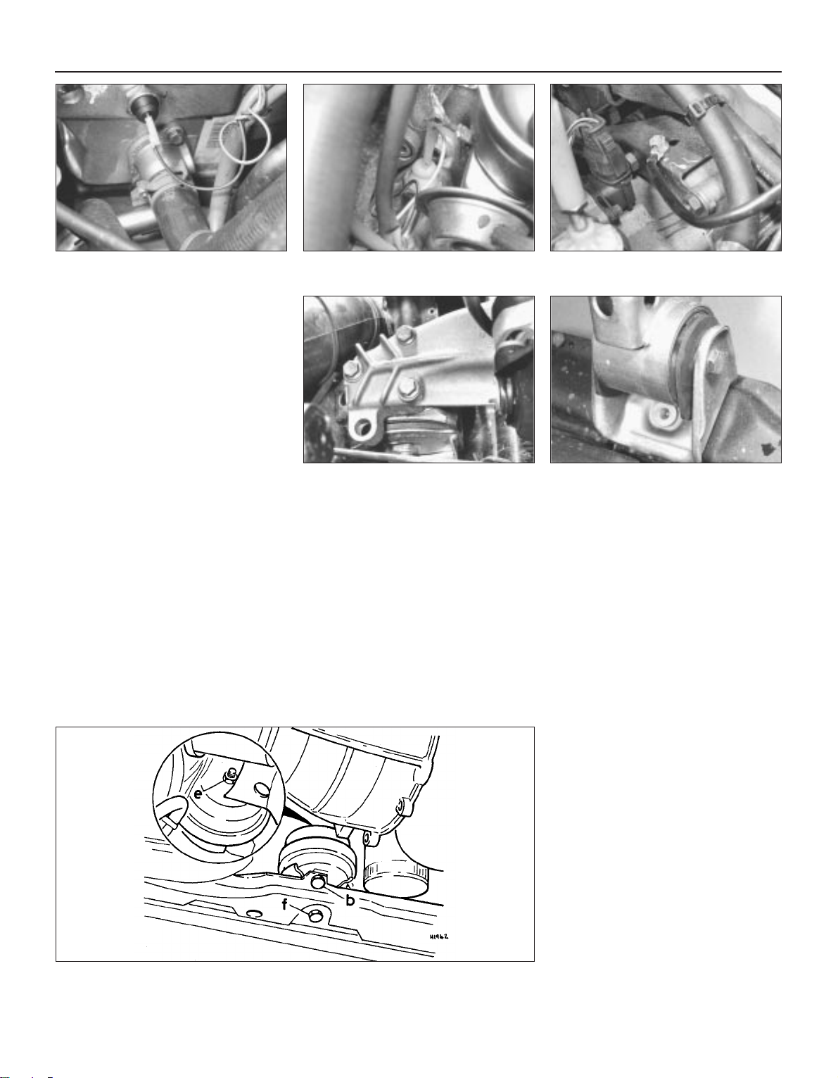
5 Remove the radiator, together with the
cooling fan. On models manufactured after
1986, remove the front panel before removing
the radiator.
6 Remove the air cleaner unit then disconnect
the throttle cable at the carburettor. Position
the cable out of the way.
7 Where power steering is fitted, remove the
hydraulic pump drivebelt. Unbolt the pump,
belt tensioner and fluid reservoir and tie them
to one side of the engine compartment.
8 Disconnect the following wiring
connections, identifying each lead as it is
detached to avoid confusion on reassembly:
a) Alternator lead
b) Oil pressure switch lead(s) at cylinder head
(see illustrations) and oil filter bracket
c) Inlet manifold preheater thermo-switch
lead
d) Choke cover thermo-switch lead (where
applicable)
e) Ignition HT and LT leads
f) Choke cover lead separate connector
g) Coolant temperature sender unit lead
h) Earth strap to gearbox (see illustration)
and multi-function switch to gearbox
i) Starter motor leads
9 Disconnect the fuel supply hose from the
fuel pump and the fuel return hose (to the fuel
tank). Plug the hoses to prevent fuel leakage.
10 Disconnect the coolant and heater hoses
from the engine.
11 On manual gearbox models, disconnect
the clutch cable.
12 Disconnect the following items from
around the carburettor. Identify the
connections where necessary to avoid
confusion on reassembly:
a) Thermotime valve
b) Idle/overrun cut-off valve
c) Inlet manifold preheater separator
connector
d) Part throttle channel heater separate
connector
13 Disconnect the speedometer cable from
the transmission.
14 Disconnect and remove the vacuum
reservoir.
15 Disconnect the brake vacuum servo
hoses and the vacuum hoses from the inlet
manifold.
16 Undo and remove the gearbox mounting
bolt.
17 Raise and support the vehicle on axle
stands (see “Jacking and vehicle support”),
allowing sufficient clearance to work
underneath.
18 Disconnect the manual gearbox linkage.
19 On automatic transmission models, select
P (Park) then disconnect the throttle and
selector cables from the transmission.
20 Disconnect the driveshafts from the
gearbox and tie them up out of the way.
21 To disconnect the exhaust manifold to
downpipe connection, VW tool no. 3049A will
be required. Although it may be possible to
prise the clips free to separate this joint, the
tool will definitely be required to refit the
springs.
22 The vehicle can now be lowered, the
remaining removal operations being from
above.
23 Attach a suitable sling and hoist to the
engine/gearbox unit and take its weight.
24 Disconnect the rear engine bearer by
undoing the three bolts (see illustration).
25 The engine/gearbox unit front mounting
must now be detached by unscrewing and
removing the single through-bolt. It may be
necessary to further lift, lower or twist the unit
to allow the through-bolt to be withdrawn (see
illustration). Note that from December 1984,
the front mounting is changed from the
bonded rubber type to a ‘hydro’ type with
damping action (see illustration).
2C•6 Engine repair procedures - 1.6 and 1.8 litre 8 valve
5.8a Oil pressure switch location in rear of
cylinder head
5.8b Oil pressure switch location in filter
mounting
5.8c Earth strap to gearbox
5.24 Engine rear bearer 5.25a Engine/gearbox unit front mounting
5.25b Hydro-type front engine mounting
Refer to Specifications for fastener torque wrench settings b, e and f
1081 VW Golf & Jetta
Page 73
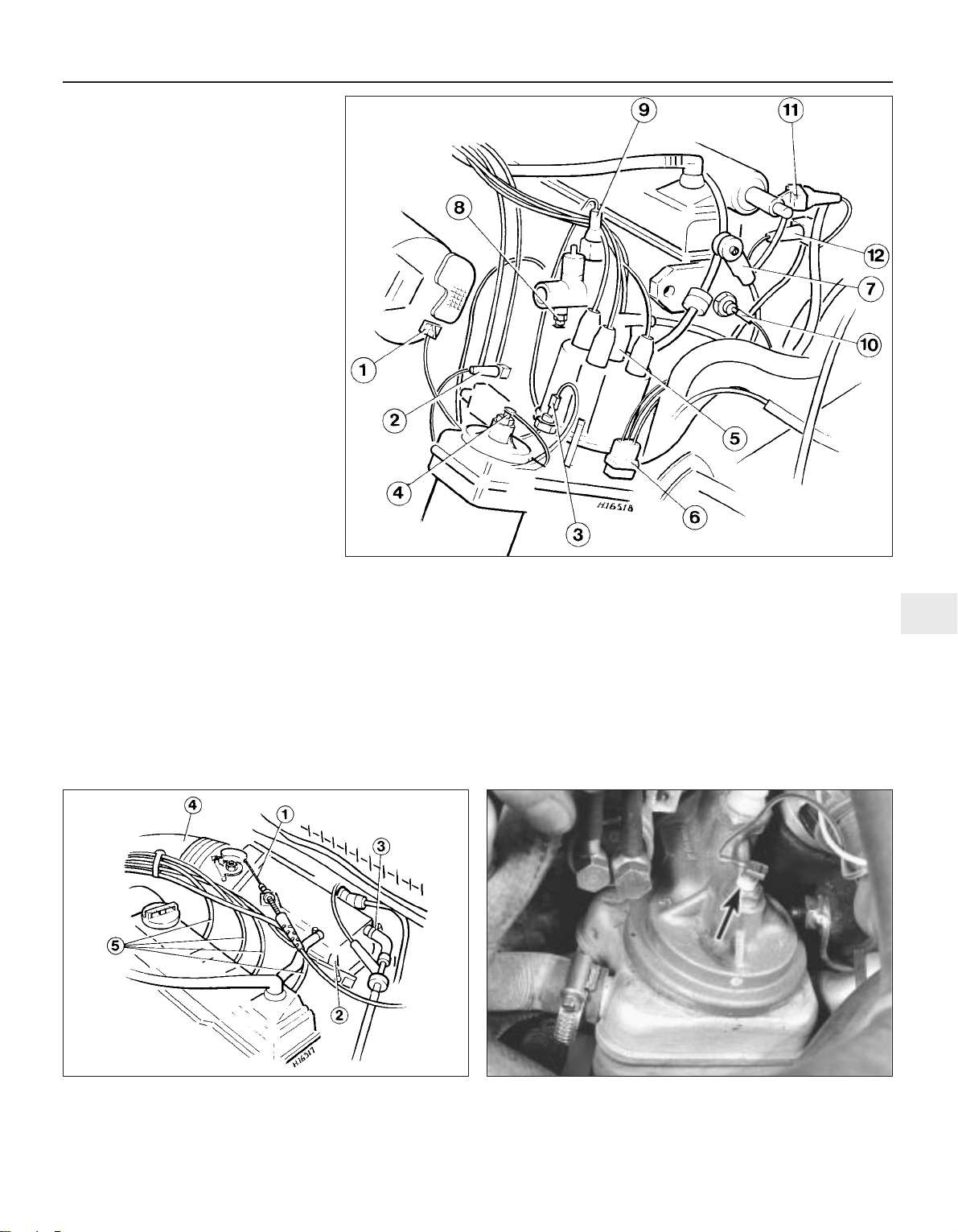
26 The engine/gearbox unit is now ready for
lifting out but first make a final check that all
cables, wiring and hoses are clear.
27 Have an assistant at hand to help guide
the unit clear of the surrounding components
in the engine compartment as it is lifted out.
The unit will have to be twisted slightly as it is
raised. Once clear of the vehicle, lower it to
the work surface.
Fuel injection equipped
28 On fuel injection equipped engines, the
removal procedure closely follows that given
for carburettor equipped engines. However,
disregard those items concerning detachment
of the carburettor and associated items. The
following injection equipment items will need
to be disconnected instead. Refer to Chapter
4 for further details:
29 Disconnect the wires from the warm-up
valve (green connector) (see illustration).
30 Disconnect the wiring to the cold start
valve (blue connector).
31 Disconnect the wiring to the auxiliary air
valve.
32 Disconnect the throttle cable at the fast
idle cam and bracket but do not remove the
securing clip (see illustration).
33 Remove the cold start valve but leave the
fuel lines connected. Place out of the way.
34 Disconnect the air inlet pipe at the flexible
ducting attached to the throttle housing.
35 Disconnect the vacuum hoses from the
inlet manifold and vacuum booster.
36 Leaving the fuel lines connected, undo the
retaining bolts and withdraw the warm-up
valve from the cylinder block. Position out of
the way.
37 Detach the injectors from the cylinder
head and plug the holes. Disconnect the
injector lines from the locating bracket on the
throttle housing and fold them out of the way.
38 Detach the vacuum hoses to the throttle
housing T-piece connector location clip at the
bulkhead. Fold the hoses back out of the way.
39 Disconnect the oil temperature switch
sender lead (see illustration).
40 When lifting out the engine/gearbox unit,
greater care will have to be taken in
manoeuvring the unit from the engine
compartment due to the close proximity of the
air inlet manifold to the bulkhead. The unit will
need to be pulled forwards first then twisted
and lifted.
Engine repair procedures - 1.6 and 1.8 litre 8 valve 2C•7
2C
1081 VW Golf & Jetta
5.29 Wiring connections to be detached - fuel injection models
1 Alternator
2 Warm-up valve
3 1.8 bar oil pressure
switch
4 Oil temperature sender
5 Distributor HT cable
(terminal 4)
6 Hall sender (distributor)
7 Vacuum switch
8 Coolant temperature
sender
9 Thermotime switch
10 0.3 bar oil pressure
switch
11 Cold start valve
12 Auxiliary air valve
5.32 Fuel injection components to be detached
1 Throttle cable
2 Cold start valve
3 Vacuum hoses
4 Air intake pipe
5 Injectors
5.39 Oil temperature sender (arrowed)
Page 74
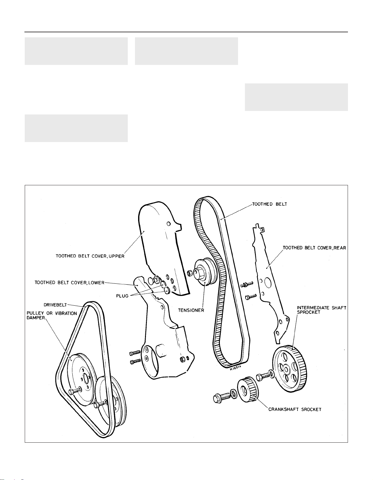
6 Engine/gearbox - separation
and reconnection
3
This procedure is fully described in Chapter
7, Parts A or B, as applicable. It is only
necessary to refer to those paragraphs
pertinent to the particular method being used.
The engine must be supported on blocks, or
alternatively the gearbox can be separated
with the engine still on the hoist.
7 Engine dismantling - general
information
Refer to Section 7 in Part A of this Chapter.
8 Engine ancillary components
- removal
3
With the engine removed from the vehicle
and separated from the transmission, the
externally mounted ancillary components can
be removed prior to engine dismantling. The
removal sequence need not necessarily follow
the order given:
a) Alternator and drivebelt
b) Inlet manifold and carburettor or inlet
manifold and throttle housing (fuel
injection)
c) Exhaust manifold
d) Fuel pump
e) Warm-up valve (fuel injection), if still
attached
f) Distributor
g) Oil filter with cooler (where applicable)
and filter mounting
h) Oil pressure and coolant temperature and
sensor switches
I) Coolant pump and coolant hose
connectors from cylinder block and head.
New O-rings will be required
j) Clutch then intermediate plate (manual
gearbox)
k) Driveplate, noting location of spacer and
shim(s) (automatic transmission)
9 Timing belt and sprockets -
removal
3
1 If the engine is still in the vehicle, first carry
out the following operations:
a) Disconnect the battery earth lead
b) Remove the alternator drivebelt
c) Unbolt and remove the coolant pump
pulley
2 Depending on type, undo the retaining
bolt(s)/nut(s), release the retaining clips and
remove the upper timing cover (see
illustration). On some engines it will be
necessary to remove the bung from the front
2C•8 Engine repair procedures - 1.6 and 1.8 litre 8 valve
1081 VW Golf & Jetta
9.2 Timing belt and cover components
Page 75
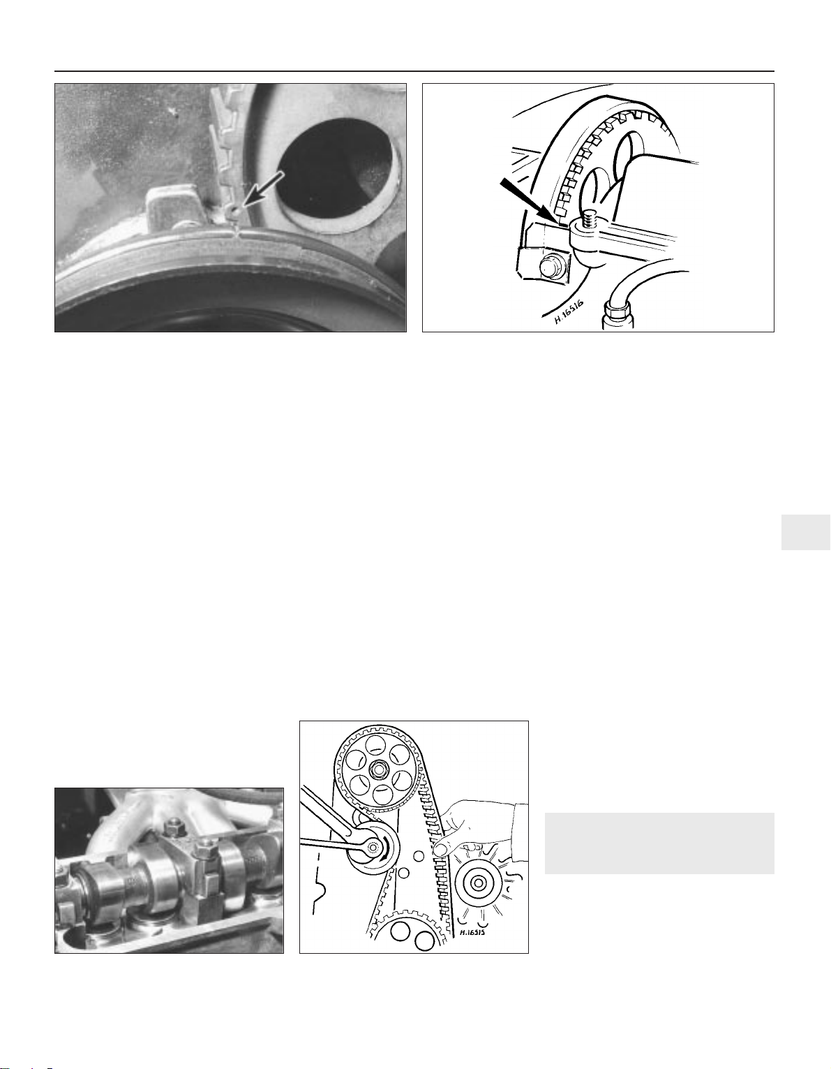
face of the cover to allow access to the Allen
type retaining screw recessed within the
cover. On other engines, the retaining screw
can be seen but its key slot is deeply
recessed (access to it being made via the hole
in the centre of the screw surround).
3 Unscrew the nuts and bolts from the valve
cover and remove the cover together with the
gasket and reinforcement strips. Detach the
crankcase emission hose(s) from the rocker
cover.
4 Mark the relative positions of the crankshaft
pulley and crankshaft sprocket, then undo the
four socket-head bolts and withdraw the
pulley.
5 Unbolt and withdraw the lower timing
cover.
6 The engine must now be set for timing.
Temporarily refit the crankshaft pulley. On the
intermediate sprocket for the timing belt one
tooth has a centre-punch mark. Turn the
engine until this mates with a notch on the
V-belt pulley bolted to the crankshaft sprocket
(see illustration). To turn the engine over,
remove the spark plugs then fit a suitable
spanner onto the crankshaft sprocket
retaining bolt and turn it in the direction of
engine rotation.
7 When these marks match, look at the
sprocket on the camshaft. One tooth of this
has a centre-punch mark. This should be level
with the valve cover flange (see illustration).
Having turned the engine until these marks
agree, now look at the cams for No 1 cylinder
(nearest the timing belt). They will both be in
the ‘valve closed’ position (see illustration).
Now look through the hole in which the TDC
sensor goes where the timing marks show on
the periphery of the flywheel and note the
reading.
8 Before removing the timing drivebelt, check
its correct tension. If held between the finger
and thumb halfway between the intermediate
shaft and the camshaft it should be just
possible to twist it through 90° (see
illustration). If it is too slack, adjust it by
slackening the bolt holding the eccentric cam
on the tensioner wheel. If you are satisfied it
can be adjusted to the correct tension,
remove it and examine it for wear. Now is the
time to order a new one if necessary.
9 Loosen the tensioner then withdraw the
timing belt from the camshaft, intermediate
and crankshaft sprockets.
10 Each of the timing belt sprockets is
secured by a central bolt and washer. The
intermediate, camshaft and crankshaft
sprocket (the latter in particular) securing
bolts are tightened to a substantial torque and
the sprockets will therefore need to be firmly
held when undoing the bolts.
11 To remove the camshaft sprocket,
unscrew the bolt with the sprocket held
stationary by inserting a suitable metal bar
through a sprocket hole and resting it on the
valve cover face of the cylinder head, but take
care not to damage the face. Remove the bolt
and spacer washer then withdraw the
sprocket, tapping it free if necessary. Check
the fit of the Woodruff key in the camshaft, it
must be renewed if loose in its groove. Lever
out the Woodruff key and keep it with the
sprocket.
12 To remove the crankshaft sprocket, hold
the crankshaft stationary with a lever jammed
in the starter ring gear (remove the starter
motor as applicable). Do not allow the
crankshaft to turn or the pistons may touch
the valve heads. Unscrew the retaining bolt
and remove it, together with the spacer
washer, then lever the sprocket free from the
crankshaft. Check the fit of the Woodruff key
(if fitted) in the crankshaft, it must be renewed
if loose in its groove. Lever out the Woodruff
key and keep it with the crankshaft sprocket.
13 The intermediate shaft sprocket is
removed in a similar manner to that for the
camshaft sprocket.
10 Camshaft - removal,
examination and refitting
3
Removal
1 To remove the camshaft with the engine in
the vehicle, first carry out the following
operations:
a) Remove the timing cover and valve cover,
then disconnect the timing belt from the
camshaft sprocket
Engine repair procedures - 1.6 and 1.8 litre 8 valve 2C•9
2C
9.7b No. 1 cylinder cam lobes in valve
closed position
9.8 Timing belt tension check method
1081 VW Golf & Jetta
9.6 Intermediate sprocket timing mark (arrowed) aligned with
notch in crankshaft pulley
9.7a Camshaft sprocket timing mark (arrowed) with No 1 cylinder
at TDC on compression
Page 76
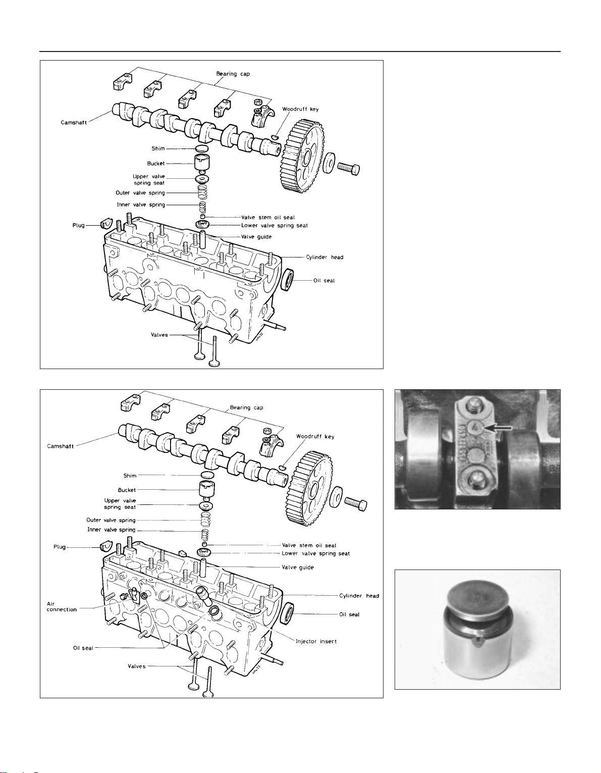
b) If the camshaft oil seal is to be renewed
then the camshaft timing sprocket must
be removed
2 Remove the camshaft bearing caps (see
illustrations), making a careful note of their
fitted positions for reference when refitting .
The caps are numbered (see illustration) but
mark the side nearest the front of the cylinder
head. No. 1 cap is the one with a small oil seal
on it.
3 Remove cap nos. 5, 1 and 3 in that order.
Now undo the nuts holding 2 and 4 in a
diagonal pattern. The camshaft will lift the
caps up as the pressure of the valve springs is
exerted. When they are free, lift the caps off
along with the camshaft. The oil seal on the
front end of the camshaft will come with it.
Depending on tappet type, proceed as
follows:
Shim bucket tappets
4 The tappet buckets are now exposed and
may be lifted out (see illustration). Take each
one out in turn, prising the little disc out of the
bucket by inserting a small screwdriver either
side and lifting the disc away. On its reverse,
each disc is engraved with a size (eg. 3.75).
This is its thickness number. Note the number
and then clean the disc and refit it, number
side down. There are eight of these and they
must not be mixed up. On assembly, each
disc must go back into the bore from whence
it came. This problem exists also for the
valves, so a container for each valve assembly
2C•10 Engine repair procedures - 1.6 and 1.8 litre 8 valve
1081 VW Golf & Jetta
10.2a Cylinder head and camshaft components - carburettor engine
10.2b Cylinder head and camshaft components - fuel injection engine
10.4 Tappet bucket and shim
10.2c Camshaft bearing cap number
(arrowed)
Page 77
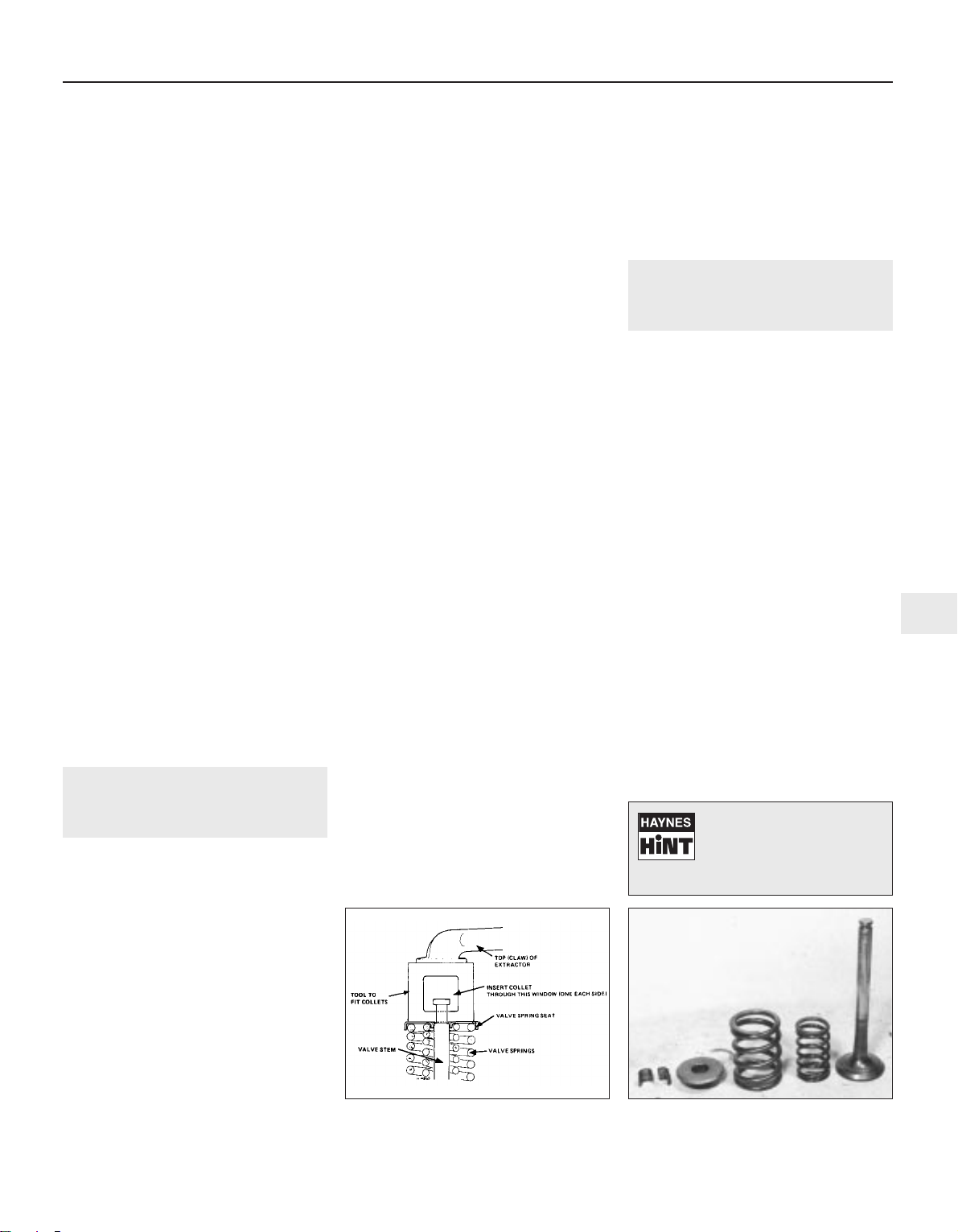
and tappet is required. Label the containers 1
to 8, as follows:
Containers 1 and 2 will be No 1 cylinder
exhaust and inlet respectively
Containers 3 and 4 will be No 2 cylinder
exhaust and inlet respectively
Containers 5 and 6 will be No 3 cylinder
inlet and exhaust respectively
Containers 7 and 8 will be No 4 cylinder
inlet and exhaust respectively
5 Note the thickness of all tappet clearance
discs from Nos. 1 to 8 for use during
reassembly.
Hydraulic bucket tappets
6 Lift out the tappets one by one, ensuring
that they are kept in their correct order and
can be returned to their original bores.
7 Place them, cam contact surface down, on
a clean sheet of paper as they are removed.
8 Inspect the tappets for wear (indicated by
ridging on the clean surface), pitting and
cracks.
9 Tappets cannot be repaired and if worn,
must be renewed.
Examination
10 Refer to Section 27 in Part A of this
Chapter whilst noting that on exchange
engines or cylinder heads, the camshaft is
supplied with bearing shells instead of running
directly in the head and bearing caps.
Exchange units supplied by VW may have an
undersized camshaft with corresponding
bearing shells. Where this is the case, the
camshaft will have a yellow paint spot on it
and the journal diameter will be 25.75 mm. An
unmarked camshaft supplied with bearing
shells will be of standard size with a journal
diameter of 26.00 mm.
Refitting
11 Refer to Section 12.
11 Cylinder head - removal
3
All engines
1 If the cylinder head is being removed with
the engine out of the vehicle, proceed from
paragraph 17. If the cylinder head is being
removed with the engine in the vehicle, it is
best removed with the inlet and exhaust
manifolds. The manifolds can then be
detached after removal of the cylinder head
but note that a special tool is required to
release (and subsequently reconnect) the
exhaust downpipe-to-manifold flange retaining
clips. A splined key will also be required to
undo and tighten the cylinder head bolts.
2 Disconnect the battery earth lead. Drain the
cooling system, then disconnect the cooling
and heater hoses from the cylinder head.
3 Disconnect the thermoswitch and oil
pressure lead connections.
4 On carburettor models, remove the air
cleaner unit.
5 Disconnect the alternator from the cylinder
head attachment brackets and remove the
drivebelt.
6 If removing the manifolds with the cylinder
head, disconnect the vacuum hose from the
inlet manifold and the accelerator cable (and
choke cable if applicable) from the
carburettor.
7 Disconnect the HT leads from the spark
plugs.
Fuel injection equipped engines
8 Detach the injector lines from the cylinder
head and location clips and fold them back
out of the way.
9 Disconnect the inlet duct at the flexible
hose connection to the throttle valve housing.
10 Detach the vacuum hoses to the throttle
valve housing and at the three-way connector
on the bulkhead side of the cylinder head.
Fold back and secure the hoses out of the
way.
11 Disconnect the auxiliary air valve lead
from the underside of the inlet manifold and
the auxiliary air valve hose to the flexible hose
on the throttle valve housing.
12 Disconnect the servo vacuum hose from
the green connector on the flexible hose on
the throttle housing.
13 If air conditioning is fitted, detach the
hoses from the auxiliary air valve and tube
connections.
14 Detach the MFI hose at the servo hose
valve connection.
15 Detach the wiring connector from the cold
start valve.
All engines
16 Remove the timing cover and valve cover,
then disconnect the timing belt from the
camshaft sprocket.
17 Remove the camshaft.
18 Remove the cylinder head bolts. These
are recessed in the well of the cylinder head
and are socket-head bolts. They must be
removed using the correct splined tool.
19 The cylinder head bolts must be
unscrewed in a progressive manner and in the
reverse sequence to that shown for
tightening.
20 When all ten bolts have been removed, lift
the head from the cylinder block. It may need
a little tapping to loosen it but do not try to
prise it loose by hammering in wedges. Lift off
the gasket and, if the engine is not being
dismantled, clean the piston crowns and
block face. Note that the cylinder head bolts
must not be re-used, a new set will need to be
obtained when ordering the cylinder head
gasket set.
12 Cylinder head - dismantling
and overhaul
3
1 Using a wire brush, scraper and steel wool,
clean all carbon from the combustion
chambers, valve faces and exhaust ports.
Remove the spark plugs for cleaning.
2 The valves are not easy to get out unless a
suitable valve spring compressor is available.
Because the collets and spring caps are set
so far down in the head, a long claw is
necessary on the compressor and it must be
split sufficiently to enable the collets to be
removed and inserted. If such a tool is not to
hand then find a piece of steel tube of about
25 mm inside diameter which will fit over the
valve stem and press down the spring cover
(see illustration). The length will depend on
the size of the compressor so fit the
compressor over the head fully extended,
measure the distance between the claw and
the valve spring seat and cut the tube to a
suitable length.
3 The next step is to cut two windows of
suitable size (approx. 25 mm long and 16 mm
wide) in opposite sides of the tube. The tube
may then be used with the compressor to
extract the collets from each valve stem in
turn. Place the valve, springs, collets and
seats with the tappet in the appropriate
receptacle, keeping them strictly together for
refitting in the valve guide from which they
were taken (see illustration).
Engine repair procedures - 1.6 and 1.8 litre 8 valve 2C•11
2C
12.2 Improvised tool used to remove and
refit collets to valve stems
12.3 Valve springs, cap and collets
1081 VW Golf & Jetta
If your fingers are too big,
put a blob of grease on the
collet and pick it up with a
small screwdriver, then
insert it into the slot on the valve stem.
Page 78
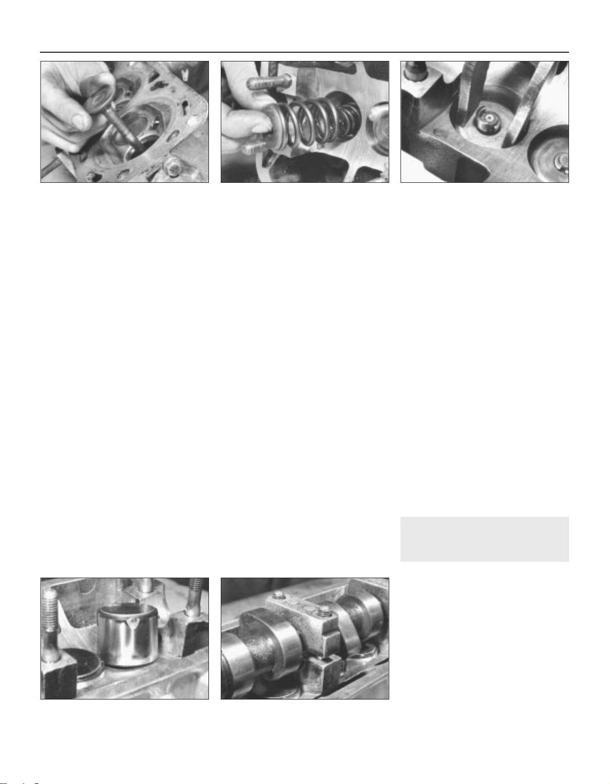
4 The valve springs must be renewed if they
are damaged, distorted, or known to have
covered a high mileage. If in doubt as to their
condition, have your VW dealer check them
for compression efficiency using a calibrated
valve spring compressor.
5 The valves should be cleaned and checked
for signs of wear or burring. Where this has
occurred, the inlet valve may be reground on
a machine at a dealer. Exhaust valves must
not be reground on the machine but ground in
by hand. On engines fitted with hydraulic
tappets, valves should not be re-cut as this
will adversely affect the operation of the
tappets.
6 Wear in the valve guides may be detected
by fitting a new valve in the guide and
checking the amount that the rim of the valve
will move sideways when the top of the valve
stem is flush with the top of the valve guide.
The valve rock limits are given in the
Specifications. New valve guides must be
fitted and reamed by your VW dealer.
7 Do not spend too long grinding in the
valves. If the valve seat and valve are not
satisfactory after 15 minutes then you will
probably do more harm than good by going
on. Make sure both surfaces are clean, smear
grinding paste onto the valve evenly and using
a suction cup, work the valve with an
oscillating motion lifting the valve away from
the seat occasionally to stop ridging. Clean
the seat and valve frequently and carry on
until there is an even grey band on both seat
and valve then wipe off all the paste.
8 The surface of the head must be checked
with a straight-edge and feeler blade. Place
the straight-edge along the centre of the
machined face of the head. Make sure there
are no ridges at the extreme ends and
measure the clearance with feelers between
each combustion chamber head. This is the
area where the narrowest part of the cylinder
head gasket comes and where the gasket is
most likely to fail. If the straight-edge is firmly
in place and feelers in excess of 0.1 mm can
be put between the head and the
straight-edge, then the head should be taken
to a dealer for servicing or replacement.
9 If the cylinder head shows signs of
cracking, have it inspected by your VW dealer
to assess its condition for reuse.
10 VW recommend that the valve stem oil
seals should always be renewed to prevent
possible high oil consumption. Pulling off the
old seal is simple with pliers. With a packet of
new oil seals is a small plastic sleeve. This is
fitted over the valve stem and lubricated. The
seal should then be pushed over the plastic
sleeve until it seats on the guide. This should
be done with VW tool 10 204 which fits snugly
round the outside of the seal and pushes it on
squarely. If the seal is assembled without the
plastic sleeve, it will be damaged and oil
consumption will become excessive.
11 Before reassembling the cylinder head,
check the condition of the camshaft.
12 When all components have been
examined, then assembly of the head may
commence. Insert the valve in the correct
guide, fit the inner seat, valve springs and
outer cap, assemble the valve spring
compressor and possibly the small tube and
compress the valve spring until the collets
may be assembled to the valve stem (see
illustrations).
13 Assemble the second collet and holding
them carefully together in place, ease off the
compressor until the spring seats the collets
home. Remove the compressor, put a rag
over the valve stem and tap the stem with a
hammer. This is to ensure that the collets are
seated correctly. If they are they will not come
out. Repeat until all eight valves are in position
in the cylinder head.
14 Refit the tappets in the bores from which
they came, lubricating them liberally with
clean engine oil (see illustration). Lubricate
the camshaft bearing surfaces with oil and fit
the camshaft, positioned so that No 1 cylinder
cams point upwards.
15 Fit a new oil seal at the sprocket end,
lubricate the bearings, set the shaft in position
and install bearing caps Nos 2 and 4,
tightening the nuts in a diagonal pattern until
the shaft is in place (see illustration). Now
install the other bearing caps, making sure
they are the right way round (marks towards
the drive pulley) and tighten the caps down
using a diagonal pattern to the specified
torque. Install a new rubber seal at the
opposite end to the sprocket.
16 On engines equipped with shim bucket
tappets, adjust the valve clearances.
13 Sump and oil pump - removal
and refitting
3
Modification: From August 1985, a larger
sump is fitted thereby increasing engine oil
capacity. If renewing the sump, ensure that
one of identical capacity is fitted
Removal
1 If the engine is in the vehicle then drain the
engine oil. Note that the sump plug has an
O-ring which must be renewed (see
illustration).
2 Undo the sump retaining bolts and remove
the sump from the lower face of the
crankcase. Remove the sump gasket which
must also be renewed.
3 To remove the oil pump, undo the two
retaining bolts and lower the pump unit,
2C•12 Engine repair procedures - 1.6 and 1.8 litre 8 valve
12.12a Inserting a valve into the cylinder
head
12.12b Locating valve springs and cap . . . 12.12c . . . and valve collets
12.14 Fit the tappet buckets 12.15 Fit the bearing caps
1081 VW Golf & Jetta
Page 79
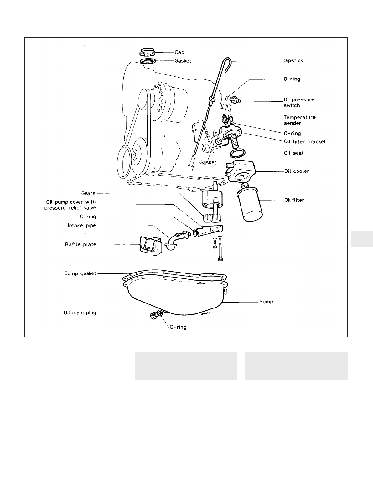
complete with the oil pick-up pipe and
strainer.
Refitting
4 To refit the pump, ensure that the mating
faces are clean, locate it in position and fit and
tighten the securing bolts to the specified
torque.
5 Locate the new sump gasket but do not
apply an adhesive sealant. Refit the sump and
tighten the retaining bolts evenly to the
specified torque.
6 Refit the oil drain plug with O-ring and
tighten it to the specified torque.
14 Pistons and connecting rods
- removal
3
1 Remove the cylinder head.
2 Remove the sump.
3 Unscrew the two oil pump retaining bolts
then lower and remove the pump, complete
with oil pick-up pipe from the crankcase.
Place it on one side for cleaning and
inspection.
4 The piston and connecting rod removal
procedure now follows that given for the smaller
engine variants in Part A of this Chapter.
15 Crankshaft and main
bearings - removal
3
1 Disconnect the pistons and connecting
rods from the crankshaft. Note that, although
the engine has to be removed to remove the
crankshaft, the cylinder head, pistons and
connecting rods can be left in position.
2 At the flywheel end, undo and remove the
six bolts securing the oil seal flange to the
crankcase (see illustration). Withdraw the
flange, seal and gasket.
3 Examine the main bearing caps. It will be
Engine repair procedures - 1.6 and 1.8 litre 8 valve 2C•13
2C
1081 VW Golf & Jetta
13.1 Sump, oil pump and oil filter
components - fuel injection engine
Page 80
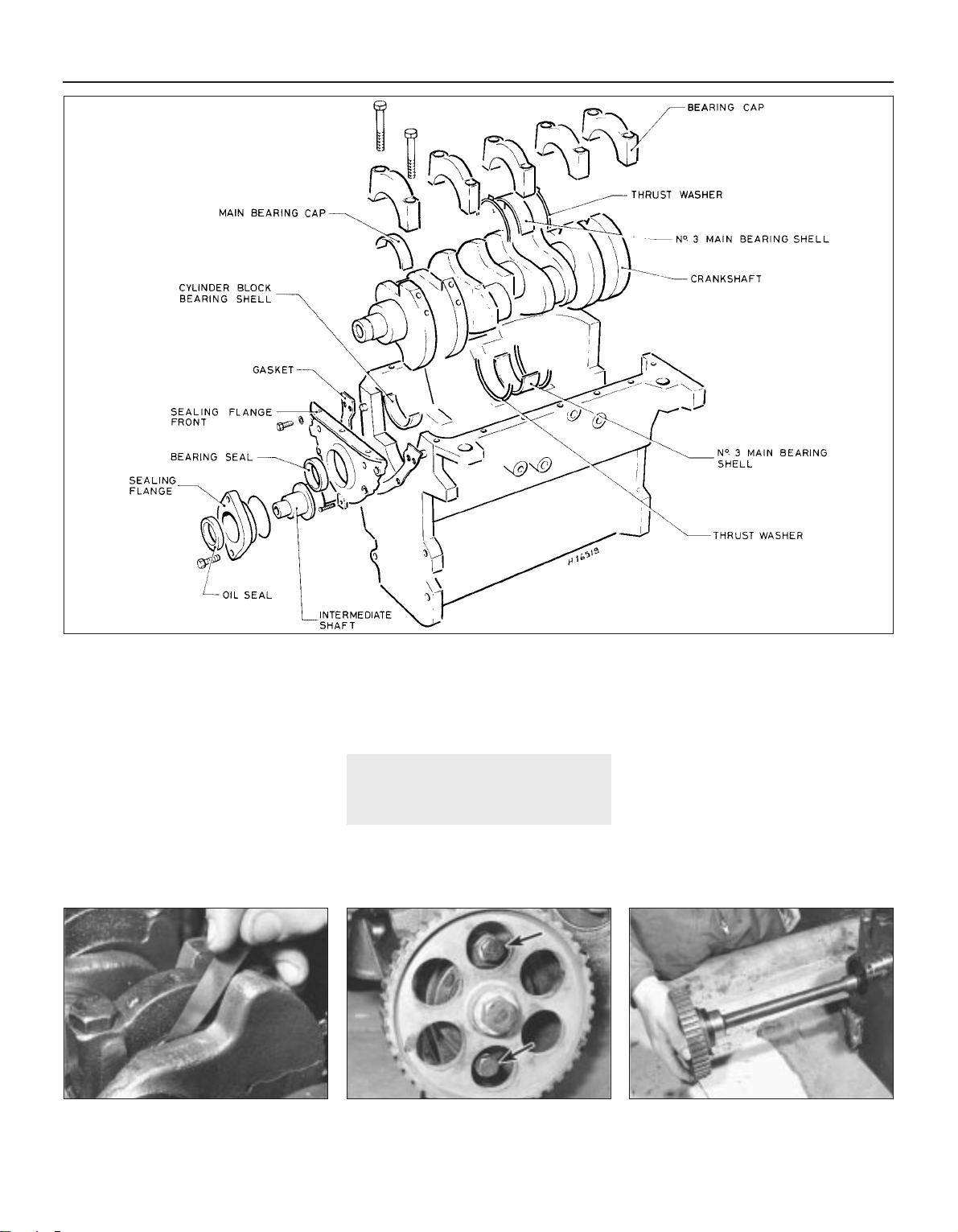
seen that the caps are numbered 1 to 5 and
that the number is on the side of the engine
opposite the oil pump position. Identify these
numbers. If they are obscured, then mark the
caps in the same way as the connecting rod
caps. Before removing the caps, push the
crankshaft to the rear and check the endfloat
using a feeler blade between the thrustwasher
flanges on No 3 main bearing and the
crankshaft web (see illustration). It must not
exceed the specified maximum.
4 Remove the bearing cap retaining bolts,
remove the bearing caps and lift out the
thrustwashers from each side of the centre
main bearing.
5 Lift out the crankshaft and then remove the
top half bearing shells. If the main bearings
are not being renewed, make sure the shells
are identified so that they go back into the
same bearing cap the same way round
16 Intermediate shaft - removal
3
1 The intermediate shaft can only be
withdrawn from the crankcase with the engine
removed from the vehicle.
2 Remove the timing belt.
3 Remove the fuel pump on carburettor
models and the ignition distributor.
4 Before removing the intermediate shaft,
check that the endfloat does not exceed the
maximum specified amount.
5 Undo the two sealing flange retaining bolts
then withdraw the intermediate shaft,
complete with sealing flange (see
illustrations).
6 Withdraw the sealing flange from the
intermediate shaft. The oil seal within the
flange and the O-ring must be renewed on
reassembly.
2C•14 Engine repair procedures - 1.6 and 1.8 litre 8 valve
15.3 Checking crankshaft endfloat at
No. 3 main bearing
16.5b Withdrawing intermediate shaft16.5a Intermediate shaft retaining flange
bolts (arrowed)
1081 VW Golf & Jetta
15.2 Crankshaft and cylinder block components
Page 81
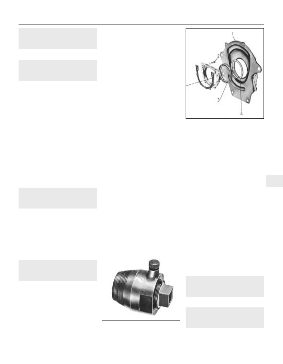
17 Oil filter - renewal
1
Refer to Chapter 1, Section 18
18 Oil cooler - removal and
refitting
2
1 On fuel injection models, an oil cooler is
fitted between the oil filter cartridge and
mounting bracket. The cooler must be
renewed if the engine oil has been
contaminated with metal particles, such as
might be the case following total or partial
engine seizure. Renew it anyway if it is likely
to contain any other harmful contaminant.
2 To remove the cooler, first remove the oil
filter cartridge.
3 Drain the cooling system and disconnect
the coolant hoses from the cooler.
4 Remove the cooler retaining nut and the
cooler. The O-ring between the cooler and
mounting must be renewed.
5 Refitting is a reversal of the removal
procedure. Wipe clean the sealing faces of the
cooler and mounting and smear the O-ring
with clean engine oil.
6 On completion, top-up the engine oil and
coolant levels. Start the engine and check for
any signs of leaks.
19 Oil filter mounting - removal
and refitting
2
1 Remove the oil filter and on fuel injection
models, the oil cooler.
2 Disconnect the oil pressure switch lead,
undo the oil filter mounting securing bolts and
withdraw the mounting and gasket.
3 The oil pressure switch can be unscrewed
from the top face of the mounting if required.
Renew the switch O-ring.
4 Refitting is a reversal of the removal
procedure. Renew the mounting gasket.
20 Oil seals - renewal
4
Note: The following procedures were all
carried out with the engine in the vehicle
Crankshaft seals
Flywheel/driveplate end
1 On manual gearbox models, remove the
clutch and pressure plate. On automatic
transmission models, remove the
transmission then unbolt the driveplate from
the crankshaft, noting the location of the
spacer and shim(s).
2 Carefully prise out the oil seal with a
screwdriver or strong wire and wipe clean the
recess (see illustration).
3 Fill the space between the lips of the new
seal with multi-purpose grease, then drive it
squarely into the housing using a block of
wood or suitable metal tubing. If at all
possible, use VW fitting sleeve No. 2003 to
avoid damage to the oil seal lip.
4 Refit the driveplate or clutch.
Timing belt end
5 Remove the alternator, together with its
drivebelt.
6 Remove the timing belt cover and timing
belt, ensuring that the timing marks are
correctly aligned.
7 Unscrew the bolt from the front of the
crankshaft, withdraw the pulley and sprocket
and remove the Woodruff key. On manual
gearbox models, if the belt is difficult to
loosen, have an assistant engage top gear
and apply the brakes. On automatic
transmission models, remove the starter
model and restrain the driveplate ring gear
with a suitable lever.
8 Prise out the oil seal or extract it with VW
tool No. 2085, then wipe clean the recess
(see illustration).
9 Fill the space between the lips of the new
seal with multi-purpose grease, then drive it
squarely into the housing using a block of
wood or suitable metal tubing. If available use
VW fitting sleeve No. 3083.
10 The remaining refitting procedure is a
reversal of removal. Ensure that the timing
marks are aligned before refitting the timing
belt and tensioning it.
Camshaft front seal
11 Remove the alternator together with its
drivebelt.
12 Remove the timing belt cover and timing
belt, ensuring that the timing marks are
correctly aligned.
13 Hold the camshaft sprocket stationary
with a screwdriver inserted through one of its
holes, then unscrew the bolt and remove the
washer, sprocket and Woodruff key.
14 Prise out the oil seal or alternatively,
extract it with VW tool No. 2085, then wipe
clean the recess.
15 Fill the space between the lips of the new
seal with multi-purpose grease, then drive it
squarely into the cylinder head using a block
of wood or suitable metal tubing. If available,
use VW fitting sleeve No. 10-203.
16 The remaining refitting procedure is a
reversal of removal. Ensure that the timing
marks are aligned before refitting the timing
belt and tensioning it.
Intermediate shaft seal
17 Remove the alternator together with its
drivebelt.
18 Remove the timing belt cover and timing
belt, ensuring that the timing marks are
correctly aligned.
19 Hold the intermediate shaft sprocket
stationary with a screwdriver inserted through
one of its holes, then unscrew the bolt and
remove the washer, sprocket and Woodruff
key.
20 Renew the oil seal.
21 The remaining refitting procedure is a
reversal of removal. Ensure that the timing
marks are aligned before refitting the timing
belt and tensioning it.
21 Examination and renovation
- general information
Refer to Section 20 in Part A of this Chapter.
22 Crankshaft and bearings -
examination and renovation
5
Refer to Section 21 in Part A of this Chapter.
Engine repair procedures - 1.6 and 1.8 litre 8 valve 2C•15
2C
20.2 Flywheel end crankshaft oil seal
components
1 Intermediate plate
2 Bolt
3 Oil seal
4 Sealing ring (not
fitted to all models)
20.8 VW tool 2085 for removing crankshaft
oil seal (timing belt end) and
camshaft oil seal
1081 VW Golf & Jetta
Page 82
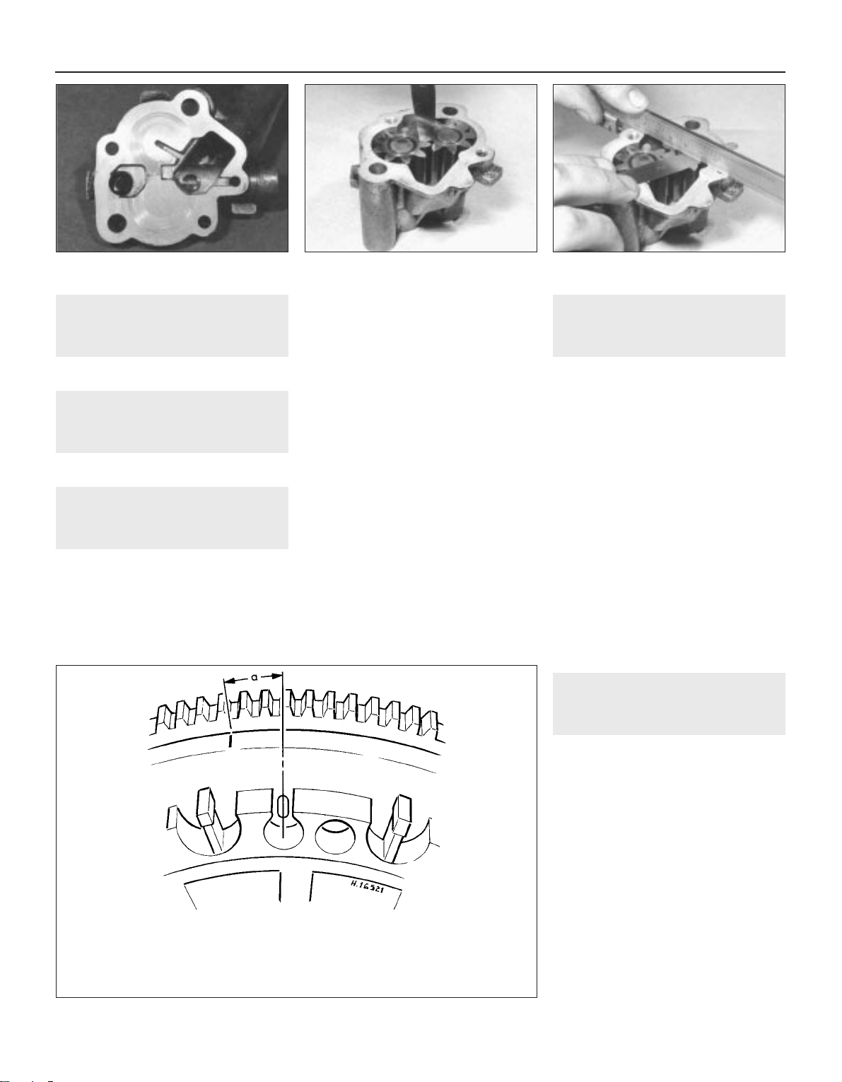
23 Cylinder block/crankcase -
examination and renovation
5
Refer to Section 22 in Part A of this Chapter.
24 Pistons and connecting rods
- examination and renovation
4
Refer to Section 23 in Part A of this Chapter.
25 Oil pump - examination and
renovation
3
1 With the oil pump on the bench, prise off
the cap with a screwdriver and clean the
strainer gauze in fuel. Refit the gauge and
press on the cap.
2 Remove the two small bolts and take the
cover away from the body. Examine the face
of the cover (see illustration). As seen in the
illustration, the gears have marked the cover.
If the depth of this marking is significant, then
the face of the cover must be machined flat
again.
3 Remove the gears and wash them with the
body in clean paraffin. Dry and reassemble
the gears, lubricating them with clean engine
oil. Measure the backlash between the gears
with a feeler blade (see illustration). This
should be 0.05 to 0.20 mm.
4 Now place a straight-edge over the pump
body along the line joining the centre of the
two gears and measure with a feeler blade the
axial clearance between the gears and the
straight-edge (see illustration). This must not
exceed 0.15 mm.
5 If all is well, check that the shaft is not slack
in its bearings and reassemble the pump for
fitting to the engine.
6 If there is any doubt about the pump, it is
recommended that a replacement be
obtained. Once wear starts in a pump it
progresses rapidly. In view of the engine
damage that may follow a loss of oil pressure,
skimping the oil pump repair is a false
economy.
26 Intermediate shaft -
examination and renovation
5
1 Check the fit of the intermediate shaft in its
bearing. If there is excessive play, the shaft
must be compared with a new one. If the shaft
is in good order but the bearings in the block
are worn, then seek expert advice.
2 Check the surface of the cam which drives
the fuel pump (where applicable). If serious
ridging is present, a new shaft is indicated.
3 Check the teeth of the distributor drivegear
for scuffing or chipping. Check the condition
of the timing belt sprocket.
4 It is unlikely that damage to the shaft has
happened but if it has, seek advice from a VW
dealer.
5 There is an oil seal in the flange for the
intermediate shaft. This may need renewal if
there are signs of leakage. To do this, remove
the timing belt sprocket and withdraw the
flange from the shaft. The oil seal may now be
prised out and a new one pressed in. Always
fit a new O-ring on the flange before
assembling it to the cylinder block.
27 Flywheel/driveplate -
examination and renovation
4
1 Inspect the starter ring teeth. If these are
chipped or worn then renew the starter ring.
This means heating the ring until it may be
withdrawn from the flywheel, or alternatively,
splitting it. A new one must then be shrunk on.
If you know how to do this and you can get a
new ring then the job can be done but it is
beyond the capacity of most owners.
2 Serious scoring on the flywheel clutch
facing requires a new flywheel. Do not
attempt to clean the scoring off with a scraper
or emery. The face must be machined.
3 If it is necessary to fit a new flywheel, the
ignition timing mark must be made by the
owner. The new flywheel has only the TDC
mark as an O on the outer face. Punch or
scribe the appropriate timing mark for your
model to the left of the TDC mark at the
appropriate distance (see illustration).
2C•16 Engine repair procedures - 1.6 and 1.8 litre 8 valve
25.2 Examine face of oil pump cover for
scoring
25.3 Checking oil pump gear backlash 25.4 Checking oil pump gear endfloat
1081 VW Golf & Jetta
27.3 Flywheel/driveplate ignition timing marks
Engine code EZ (1.6)-flywheel a = 37.0 mm 18° BTDC
Engine code EZ (1.6)-driveplate: a = 42.0 mm 18° BTDC
Engine code EV (1.8) - flywheel: a = 12.5 mm 6° BTDC
Engine code GU (1.8) - flywheel a = 37.0 mm 18° BTDC
Engine code GU (1.8) - driveplate: a = 42.0 mm 18° BTDC
Page 83
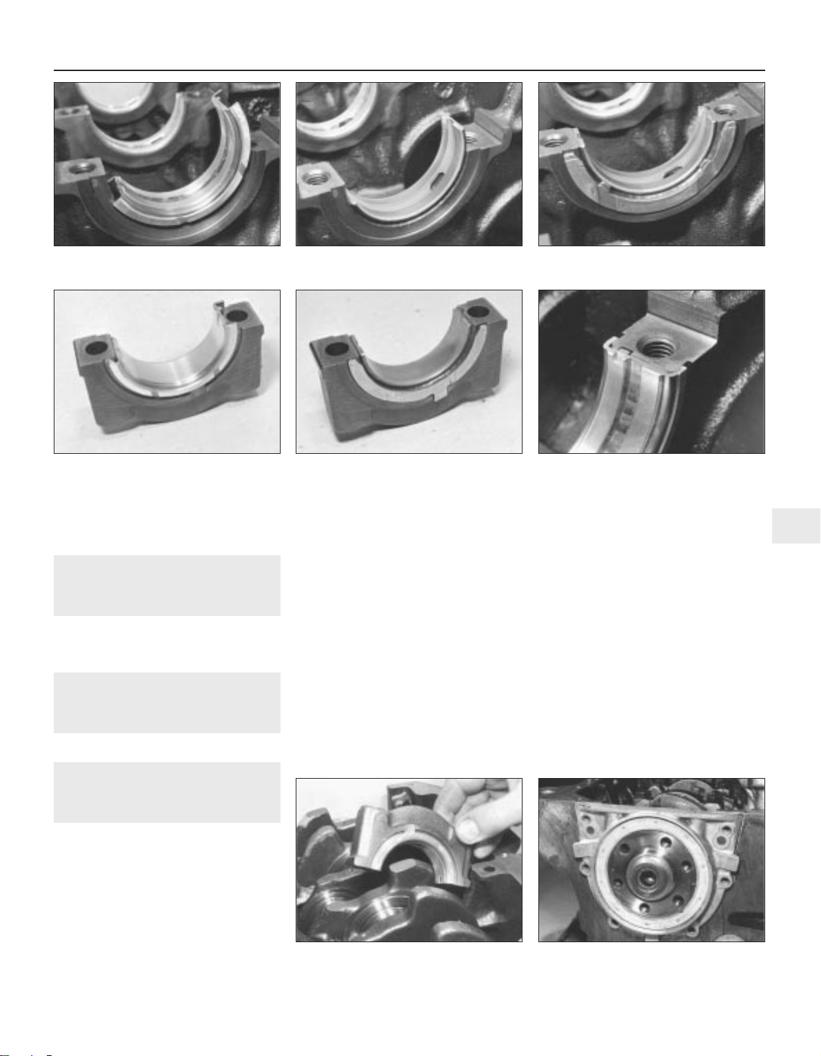
4 On automatic transmission models, check
the driveplate as described for the flywheel. It
will also be necessary to mark a new
driveplate for ignition timing.
28 Timing belt and sprockets -
examination and renovation
1
Refer to Section 26 in Part A of this
Chapter. The information given also applies to
the intermediate shaft sprocket.
29 Engine reassembly - general
information
Refer to Section 28 in Part A of this Chapter.
30 Crankshaft and main
bearings - refitting
3
Note: If it is difficult to rotate the crankshaft,
check that the bearing shells are seated
properly and that the bearing cap is in the
correct way round. Rotation will only be difficult
if something is incorrect and the fault must be
found. Dirt on the back of a bearing shell is
sometimes the cause of a tight main bearing.
1 If a new crankshaft is being fitted to
automatic transmission models, the needle
roller bearing supplied and fitted by the
manufacturer will need to be removed from its
aperture in the rear end of the crankshaft. It
may already have been removed by the
supplier, but check anyway.
2 Clean the crankcase recesses and bearing
caps thoroughly and fit the bearing shells so
that the tang on the bearing engages in the
recess in the crankcase or bearing cap.
Ensure that the shells fitted to the crankcase
have oil grooves and holes and that these
align with the drillings in the bearing housings.
When fitting the bearing shells to the caps,
note that bearing Nos. 1, 2 and 5 are plain
shells whilst No. 4 has an oil groove.
3 The bearing shells of the centre bearing
(No. 3) may either be flanged to act as
thrustwashers, or may have separate
thrustwashers. These should be fitted oil
groove outwards. Fit the bearing shells so that
the ends of the bearing are flush with the joint
face (see illustrations).
4 Oil the bearings and journals then locate
the crankshaft in the crankcase.
5 Fit the main bearing caps (with centre main
bearing thrustwashers if applicable) in their
correct positions (see illustration).
6 Fit the bolts to the bearing caps and tighten
the bolts of the centre cap to the specified
torque, then check that the crankshaft rotates
freely.
7 Working out from the centre, tighten the
remaining bearing caps in turn, checking that
the crankshaft rotates freely after each
bearing has been tightened.
8 Check that the endfloat of the crankshaft is
within specifications by inserting feeler blades
between the crankshaft and the centre
bearing thrust face/washer while levering the
crankshaft first in one direction and then in the
other.
9 Lubricate the rear of the crankshaft and
using a new gasket, install the rear oil seal and
flange. Tighten the six bolts (see illustration).
Engine repair procedures - 1.6 and 1.8 litre 8 valve 2C•17
2C
30.3a Fitting flanged type centre main
bearing into crankcase
30.3b Fitting alternative type centre main
bearing into crankcase . . .
30.3c . . . together with thrustwashers
30.5 Fitting main bearing caps 30.9 Fitting crankshaft rear oil seal and
flange
30.3d Fitting flanged type centre main
bearing to cap
30.3e Fitting centre bearing and separate
thrustwashers to cap
30.3f Ensure that ends of bearing are flush
with joint face
1081 VW Golf & Jetta
Page 84
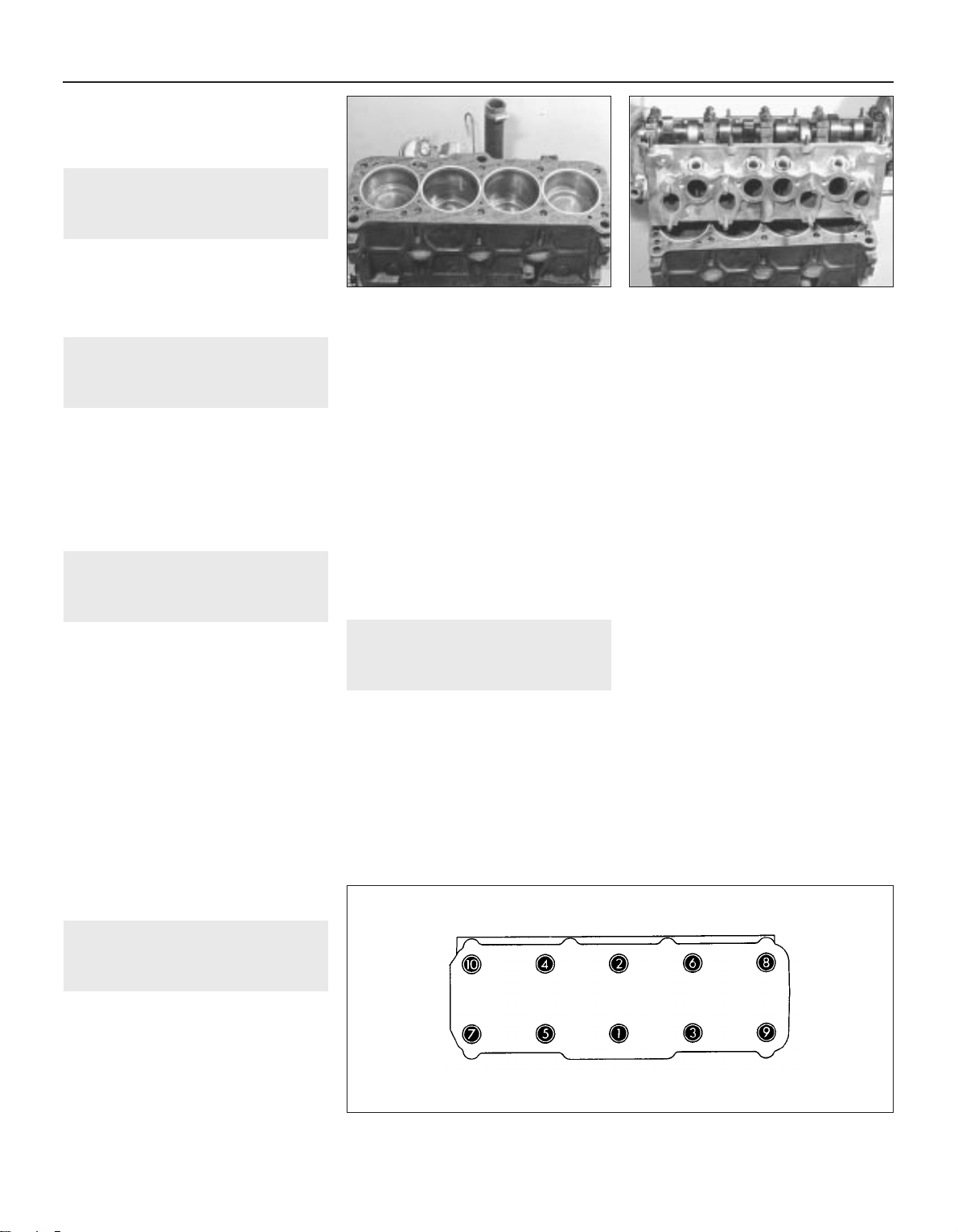
10 Lubricate the front of the crankshaft and
fit the front oil seal and flange with a new
gasket. Tighten the bolts to the correct
torque.
31 Intermediate shaft - refitting
3
Lubricate the intermediate shaft with clean
engine oil then install it in the block.
Fit the O-ring and flange, together with the
oil seal, then tighten the bolts. Note that the
oil hole must be at the bottom of the flange.
32 Pistons and connecting rods
- refitting
3
Proceed as described in Section 30, Part A
of this Chapter, paragraphs 2 to 7 inclusive.
When refitting the big-end nuts, oil the
threads.
On completion, check the endfloat of each
connecting rod in a similar manner to that
described for checking the crankshaft
endfloat.
33 Valve clearances - checking
and adjustment (pre August
1985)
3
1 If a new or reconditioned cylinder head,
complete with camshaft, is being fitted, then
the valve clearances will have been preset.
2 Valve clearances can be checked and
adjusted with the cylinder head removed
(prior to refitting after overhaul) or in the
normal manner described in Section 12 of
Chapter 1.
3 There are two specified valve clearance
settings, these being for a cold (cylinder head
removed) or warm (engine in vehicle) engine
condition.
4 If valve adjustment is made with the engine
cold, then it must be checked again with the
engine at normal operating temperature (ie.
coolant above 35°C). If the cylinder head has
been overhauled, then it should be checked
again, hot, after 600 miles (900 km).
34 Cylinder head - refitting
3
Note: New cylinder head retaining bolts must
be used on refitting
1 Clean the top face of the block. Clean and
inspect the bores and lubricate them with
clean engine oil. Turn the crankshaft so that
the pistons are in the mid-cylinder position.
2 The engine number is stamped on an
inclined surface between No. 3 and No. 4
cylinders on the side above the distributor.
Using this as a datum, install a new cylinder
head gasket so that the word ‘OBEN’ on the
gasket is over this datum point and on the top
side of the gasket (see illustration).
3 Lower the cylinder head into position,
locating onto the centring pins where fitted
(see illustration). If the cylinder block does
not have centring pins, initially refit new No. 8
and No. 10 cylinder head bolts. Do not use
jointing compound. Check that the gasket is
seating correctly and fit the remainder of the
new bolts. Following the sequence shown,
tighten the bolts until the head is firmly held.
Using a torque wrench, tighten the bolts in
stages to the specified torque following the
same sequence (see illustration).
4 The cylinder head will not need further
tightening.
35 Timing belt and sprockets -
refitting
3
1 Fit the Woodruff key into its groove in the
intermediate shaft then refit the sprocket to
the front of the shaft. Locate the spacer
washer onto the bolt then fit and tighten the
bolt to the specified torque wrench setting.
Hold the sprocket stationary when tightening
by inserting a screwdriver through one of its
holes and jamming it against the cylinder
block.
2 Locate the Woodruff key (if applicable) to
the groove at the front of the crankshaft then
refit the timing belt sprocket onto the shaft.
Lubricate the retaining bolt with oil, locate the
spacer washer onto the bolt then fit and
tighten it to the specified torque wrench
setting. When tightening the bolt, prevent the
crankshaft from turning by using the same
method as that for its removal.
3 Locate the Woodruff key into its groove on
the front of the camshaft then refit the
camshaft sprocket. Refit the retaining bolt
together with the spacer washer and tighten
to the specified torque wrench setting. Hold
the sprocket stationary when tightening by
inserting a screwdriver through one of its
holes and jamming it against the cylinder
block or head.
4 If removed, refit the timing belt rear cover.
Apply locking compound to the stud thread.
5 Locate the crankshaft pulley onto the
sprocket (aligning the marks made previously)
using one bolt to secure it temporarily.
6 Turn the camshaft sprocket so that the
lobes of No. 1 cylinder cams are pointing
upwards and the mark on the camshaft
sprocket is aligned with the valve cover - see
illustration 9.7a.
7 Rotate the crankshaft sprocket and the
intermediate shaft sprocket until the dot on
the intermediate sprocket and the mark on the
V-belt pulley coincide. Install the timing belt
tensioner loosely and then the timing belt.
Making sure the marks are still in place, put a
spanner on the adjuster and tighten the belt
until it will twist only 90 degrees when held
between the finger and thumb halfway
2C•18 Engine repair procedures - 1.6 and 1.8 litre 8 valve
34.2 Cylinder head gasket located on
block
34.3a Lowering cylinder head onto block
34.3b Cylinder head bolt tightening sequence
1081 VW Golf & Jetta
Page 85
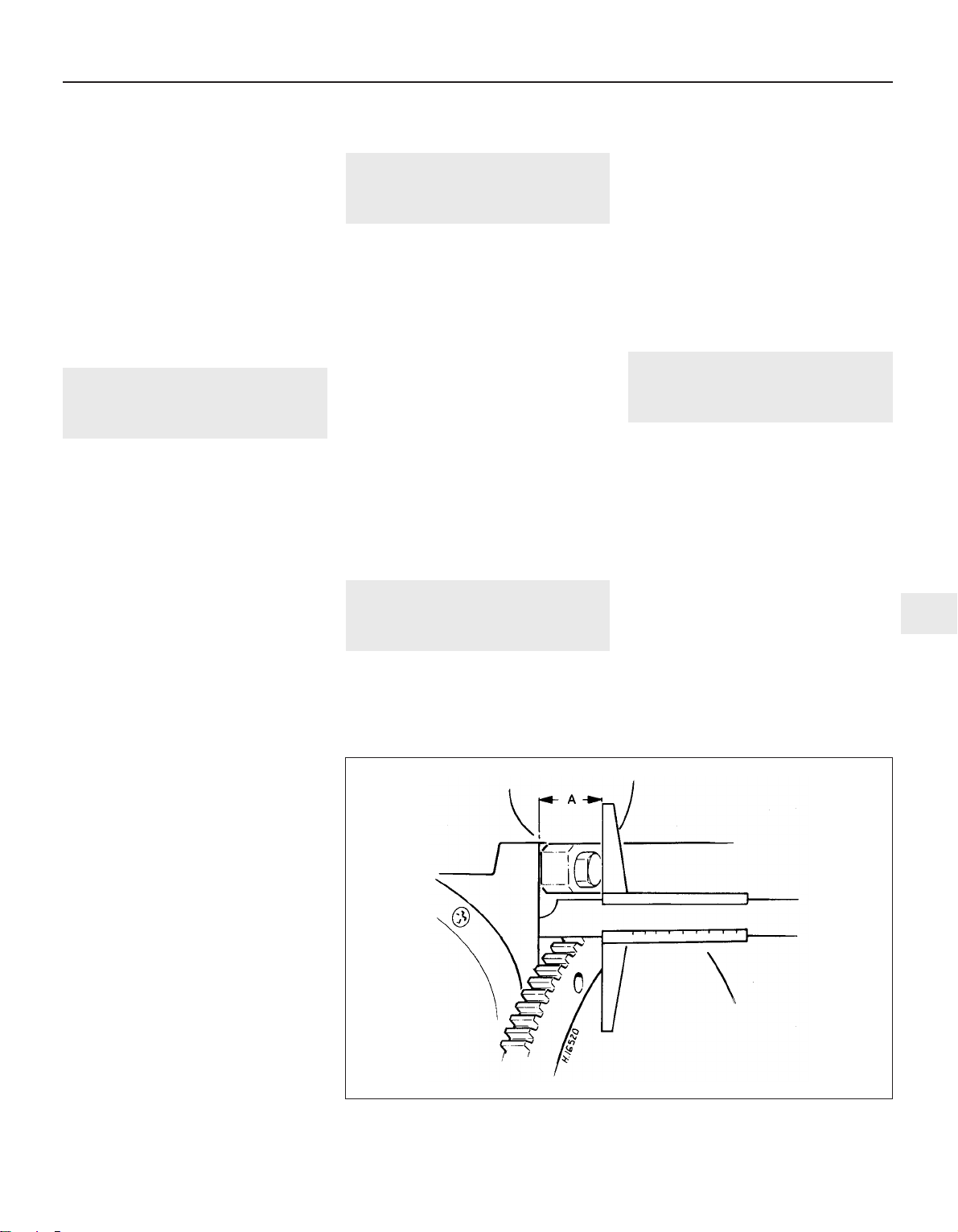
between the camshaft and intermediate shaft
sprockets. Tighten the eccentric adjuster nut
to the specified torque - see illustration 9.8.
8 Unbolt and remove the crankshaft V-belt
pulley.
9 Fit the lower timing cover then refit the
crankshaft V-belt pulley and tighten its
retaining bolts to the specified torque.
10 Locate the new valve cover gasket on the
cylinder head, the seal to the No. 1 camshaft
bearing cap and the half round grommet into
its location at the rear end of the cylinder
head.
11 Fit the valve cover into position, locate the
reinforcement strips then refit and tighten the
retaining nuts evenly to the specified torque.
12 Refit the upper timing belt cover.
36 Engine ancillary components
- refitting
3
1 On automatic transmission models, refit the
driveplate together with any shims originally
located between the crankshaft and the plate.
Fit the washer on the transmission side of the
driveplate, ensuring that the chamfered side
of the washer faces towards the driveplate.
Use new bolts and tighten them to the
specified torque setting then using vernier
calipers, check the distance between the
driveplate and the cylinder block as shown
(see illustration) at three positions. If the
clearance is not between 30.5 and 32.1 mm,
remove the driveplate, fit shims of suitable
thickness between the driveplate and the
crankshaft, then refit the driveplate assembly
and recheck the clearance. If the engine is a
new or reconditioned short block replacement, check that the bore in the rear end does
not contain a needle roller bearing. If it does,
then remove the bearing as this is for manual
gearbox models only.
2 On manual gearbox models, refit the clutch
together with the intermediate plate.
3 Refit the inlet and exhaust manifolds.
4 Refit the coolant pump and all hoses to the
engine.
5 Refit the alternator and drivebelt.
6 Refit the oil pressure switch to the cylinder
head or filter mounting as applicable, using a
new washer or O-ring. Tighten to the specified
torque.
7 Fit the oil filter mounting to the cylinder
block, together with a new gasket and tighten
the bolts. On models fitted with an oil cooler,
refit the supply and return hoses to their
correct unions.
8 Fit the oil filter.
9 Refit the distributor.
10 On carburettor models, refit the fuel
pump.
11 On fuel injection models, refit the
warm-up valve (if the hoses were
disconnected) .
12 Refit the coolant temperature sender unit
and the thermotime switch with new O-rings.
13 Refit the spark plugs, if not already done.
14 Refit the gearbox/transmission to the
engine.
37 Engine - refitting
4
To refit the engine/transmission, reverse the
removal procedures but note the following:
a) When lowering the unit into the engine
compartment, align the driveshafts with
the flanges prior to attaching the
respective mountings
b) Assemble the engine mountings loosely
initially and tighten them only after the
unit is central without straining the
mountings
c) Adjust the clutch cable (manual gearbox)
d) Adjust the throttle and selector cables
(automatic transmission)
e) Reconnect and adjust the gear selector
linkages (manual gearbox)
f) Adjust the throttle and choke cables
g) Refill the cooling system
h) Refill the engine with the correct grade
and quantity of oil
i) Where necessary, retension the power
steering pump drivebelt and replenish the
system fluid
38 Hydraulic bucket tappets -
checking free travel (from
August 1985)
2
1 Start the engine and run it until the radiator
cooling fan has switched on once.
2 Increase engine speed to about 2500 rpm
for about two minutes.
3 Irregular noises are normal when starting
but should become quiet after a few minutes
running.
4 If the valves are still noisy, carry out the
following check to identify worn tappets.
5 Stop the engine and remove the valve cover
from the cylinder head.
6 Turn the crankshaft clockwise by using a
wrench on the crankshaft pulley securing bolt,
until the cam of the tappet to be checked is
facing upward and is not exerting any
pressure on the tappet.
7 Press the tappet down using a wooden or
plastic wedge.
8 If free travel of the tappet exceeds that
specified, the tappet must be renewed.
39 Engine - adjustments after
major overhaul
2
Refer to Section 41 in Part A of this Chapter.
If new hydraulic bucket tappets have been
fitted, it is essential that no attempt to restart
the engine is made for a minimum period of
30 minutes after installation. Failure to
observe this precaution may result in engine
damage caused by the valves contacting the
pistons.
Engine repair procedures - 1.6 and 1.8 litre 8 valve 2C•19
2C
36.1 Checking driveplate-to-cylinder block dimension (A) using vernier calipers
1081 VW Golf & Jetta
Page 86

2C•20
1081 VW Golf & Jetta
Notes
Page 87

1081 VW Golf & Jetta
2D
Chapter 2 Part D:
Engine repair procedures 1.8 litre 16 valve
The following information is a revision of, or supplementary to, that given for the 1.8 litre engine in Part C of this Chapter
General
Code:
GTi 16V with catalytic converter . . . . . . . . . . . . . . . . . . . . . . . . . . . . . KR
Compression ratio . . . . . . . . . . . . . . . . . . . . . . . . . . . . . . . . . . . . . . . . . 10:1
Cylinder head
Minimum height . . . . . . . . . . . . . . . . . . . . . . . . . . . . . . . . . . . . . . . . . . . 118.1 mm - measured through cylinder head bolt hole
Valves
Head diameter:
Inlet . . . . . . . . . . . . . . . . . . . . . . . . . . . . . . . . . . . . . . . . . . . . . . . . . . . 32.0 mm
Exhaust . . . . . . . . . . . . . . . . . . . . . . . . . . . . . . . . . . . . . . . . . . . . . . . . 28.0 mm
Stem diameter:
Inlet . . . . . . . . . . . . . . . . . . . . . . . . . . . . . . . . . . . . . . . . . . . . . . . . . . . 6.97 mm
Exhaust . . . . . . . . . . . . . . . . . . . . . . . . . . . . . . . . . . . . . . . . . . . . . . . . 6.94 mm
Overall length:
Inlet . . . . . . . . . . . . . . . . . . . . . . . . . . . . . . . . . . . . . . . . . . . . . . . . . . . 95.5 mm
Exhaust . . . . . . . . . . . . . . . . . . . . . . . . . . . . . . . . . . . . . . . . . . . . . . . . 98.2 mm
Valve timing
Nil valve clearance at 1.0 mm valve lift
Inlet opens . . . . . . . . . . . . . . . . . . . . . . . . . . . . . . . . . . . . . . . . . . . . . . . 3° ATDC
Inlet closes . . . . . . . . . . . . . . . . . . . . . . . . . . . . . . . . . . . . . . . . . . . . . . . 35° ABDC
Exhaust opens . . . . . . . . . . . . . . . . . . . . . . . . . . . . . . . . . . . . . . . . . . . . 43° BBDC
Exhaust closes . . . . . . . . . . . . . . . . . . . . . . . . . . . . . . . . . . . . . . . . . . . . 3° BTDC
Torque wrench settings Nm Ibf ft
Vibration damper . . . . . . . . . . . . . . . . . . . . . . . . . . . . . . . . . . . . . . . . . . 20 15
Intermediate shaft sprocket bolt . . . . . . . . . . . . . . . . . . . . . . . . . . . . . . . 65 48
Valve cover . . . . . . . . . . . . . . . . . . . . . . . . . . . . . . . . . . . . . . . . . . . . . . . 10 7
Oil cooler . . . . . . . . . . . . . . . . . . . . . . . . . . . . . . . . . . . . . . . . . . . . . . . . . 25 19
Camshaft sprocket bolt . . . . . . . . . . . . . . . . . . . . . . . . . . . . . . . . . . . . . 65 48
Camshaft bearing caps . . . . . . . . . . . . . . . . . . . . . . . . . . . . . . . . . . . . . 15 11
Oil temperature sender . . . . . . . . . . . . . . . . . . . . . . . . . . . . . . . . . . . . . . 10 7
Oil pump cover . . . . . . . . . . . . . . . . . . . . . . . . . . . . . . . . . . . . . . . . . . . . 10 7
Oil pump mounting bolts . . . . . . . . . . . . . . . . . . . . . . . . . . . . . . . . . . . . 20 15
Oil jet . . . . . . . . . . . . . . . . . . . . . . . . . . . . . . . . . . . . . . . . . . . . . . . . . . . . 10 7
Crankshaft sprocket bolt (oiled) . . . . . . . . . . . . . . . . . . . . . . . . . . . . . . . 180 133
Camshafts - removal and refitting . . . . . . . . . . . . . . . . . . . . . . . . . . . 3
Cylinder head - dismantling and overhaul . . . . . . . . . . . . . . . . . . . . . 4
General information . . . . . . . . . . . . . . . . . . . . . . . . . . . . . . . . . . . . . . 1
Pistons and connecting rods - removal and refitting . . . . . . . . . . . . 5
Timing belt and sprockets - removal and refitting . . . . . . . . . . . . . . . 2
2D•1
Specifications
Contents
Easy, suitable for
novice with little
experience
Fairly easy, suitable
for beginner with
some experience
Fairly difficult,
suitable for competent
DIY mechanic
Difficult, suitable for
experienced DIY
mechanic
Very difficult,
suitable for expert DIY
or professional
Degrees of difficulty
5
4
3
2
1
Page 88
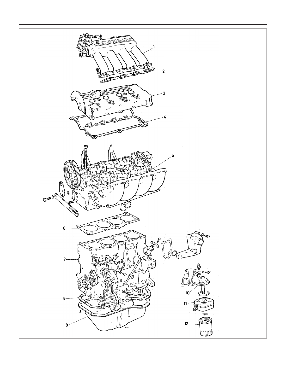
2D•2 Engine repair procedures 1.8 litre 16 valve
1081 VW Golf & Jetta
1.0 The 1.8 litre, 16 valve, fuel injection engine
1 Inlet manifold upper section
2 Gasket
3 Valve cover
4 Gasket
5 Cylinder head assembly with
camshafts
6 Cylinder head gasket
7 Cylinder block assembly
8 Gasket
9 Sump
10 Oil filter head
11 Oil cooler
12 Oil filter
Page 89
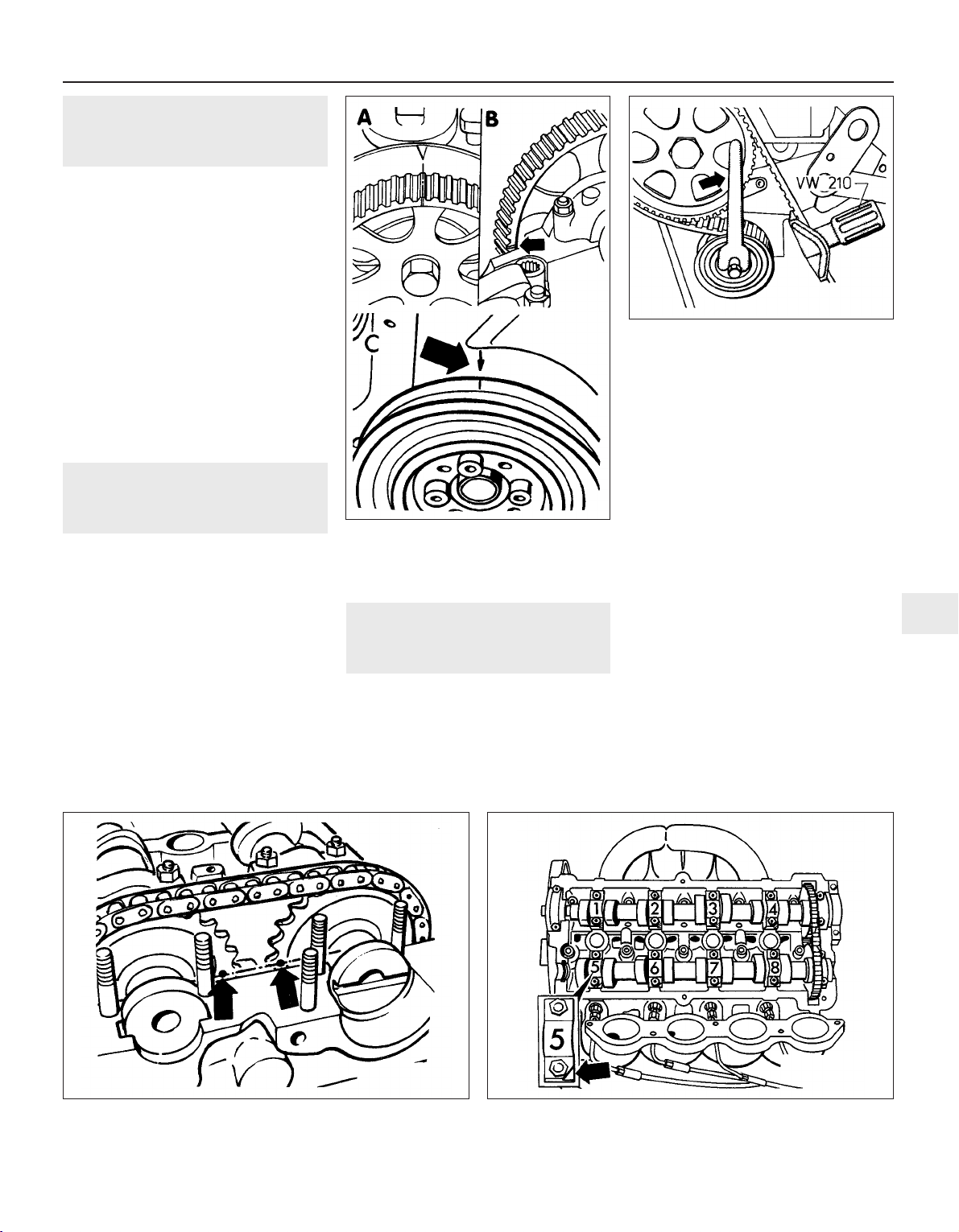
1 General information
The 1.8 litre, 16-valve engine fitted to GTi
models from October 1986, incorporates
double overhead camshafts, one operating
the exhaust valves and the other the inlet
valves. There are four valves per cylinder
which operate simultaneously in pairs and
provide the engine with a much improved
breathing capability over the 8-valve version,
thus resulting in greater power output. A
single camshaft sprocket is attached to the
exhaust camshaft and a chain and sprocket at
the opposite end of the cylinder head is used
to drive the inlet camshaft (see illustration).
Most overhaul procedures for the 16-valve
engine are basically the same as those
described for the 8-valve engine in Part C of
this Chapter. The following Sections describe
procedures which differ.
2 Timing belt and sprockets -
removal and refitting
3
Besides the timing mark on the camshaft
sprocket referred to in Part C of this Chapter,
Section 9, an additional timing mark is
provided on the outside of the camshaft
sprocket which aligns with a mark on the
valve cover (see illustration). This means that
if the timing belt alone is being renewed, it is
not necessary to remove the valve cover in
order to check the alignment marks.
When fitting the timing belt, it is
recommended that VW tool 210 is used to set
the tension accurately as this is more critical
with the DOHC arrangement (see
illustration). Using this tool, the tension
should be set to record a reading of between
13 and 14 on the scale. The tool can be
obtained from a VW dealer.
3 Camshafts - removal and
refitting
3
Removal
1 Remove the camshaft sprocket cover.
2 Unbolt and remove the upper section of
inlet manifold.
3 Unbolt and remove the valve cover after
disconnecting the HT leads from the spark
plugs. Remove the main gasket and the
central gasket from around the spark plug
locations.
4 Align the timing marks with reference to
Part C of this Chapter, then check also that
the marks on the chain sprockets are aligned
(see illustration).
5 Remove the timing belt and camshaft
sprocket with reference to Part C of this
Chapter.
6 Note the fitted positions of the camshaft
bearing caps, if necessary marking them to
ensure correct refitting (see illustration).
7 Progressively unscrew the nuts and bolts
from the end caps and bearing cap Nos. 1
and 3 on the exhaust camshaft.
8 Progressively unscrew the bolts from
bearing cap Nos. 2 and 4. The exhaust valve
springs will force the exhaust camshaft up as
the bolts are loosened. Remove the bearing
caps keeping them identified for position.
9 Working on the inlet camshaft, progressively unscrew the nuts and bolts from
the end cap and bearing cap Nos. 5 and 7.
10 Progressively unscrew the bolts from
bearing cap Nos. 6 and 8, then remove all the
caps keeping them identified for position.
11 Lift both camshafts from the cylinder head
then release them from the drive chain.
Engine repair procedures 1.8 litre 16 valve 2D•3
2D
2.1 Valve timing marks
A Camshaft sprocket outer marks
B Camshaft sprocket inner marks
C Crankshaft vibration damper marks
2.2 Adjusting timing belt tension using
VW tool 210
1081 VW Golf & Jetta
3.4 TDC timing marks in alignment on camshaft drive chain
sprockets
3.6 Camshaft bearing cap identification
Inset shows recessed corner position (arrowed)
Page 90
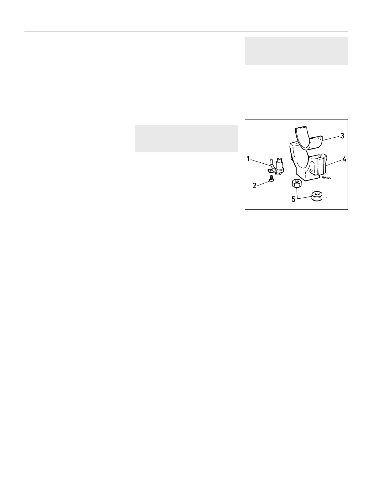
12 If necessary, remove the hydraulic bucket
tappets. Check the camshafts and drive chain
for wear.
Refitting
13 Lubricate all bucket tappets and camshaft
journals with clean engine oil, then insert the
tappets in their original bores.
14 Locate the drive chain on the camshaft
sprockets so that the timing marks are aligned
as shown in illustration 3.4, then lower the
camshafts into position on the cylinder head.
Recheck the timing mark alignment.
15 Fit a new oil seal to the front end of the
exhaust camshaft.
16 When refitting the bearing caps, make
sure that they are located the correct way
round. The numbers must be readable from
the inlet manifold side of the head. The
recessed corners of the caps must also face
the inlet manifold side of the head.
17 Refit bearing cap Nos. 6 and 8, then
progressively tighten the bolts to the specified
torque.
18 Refit the inlet camshaft end cap and
bearing cap Nos. 5 and 7, then progressively
tighten the nuts and bolts to the specified
torque.
19 Refit bearing cap Nos. 2 and 4, then
progressively tighten the bolts to the specified
torque.
20 Refit the exhaust camshaft end caps and
bearing cap Nos. 1 and 3, then progressively
tighten the nuts and bolts to the specified
torque.
21 Refit the camshaft sprocket and timing
belt with reference to Part C of this Chapter
and Section 2.
22 Check that all timing marks, including the
drive chain sprocket marks, are aligned.
23 Refit the valve cover together with new
gaskets and reconnect the spark plug HT
leads.
24 Refit the inlet manifold upper section and
the camshaft sprocket cover.
4 Cylinder head - dismantling
and overhaul
3
Exhaust valves on the 16 valve engine are
filled with sodium to provide improved heat
dissipation. Special precautions are
necessary when disposing of this type of
valve, particularly where recycling of scrap
metal is concerned.
To render each valve safe, it should be
wiped dry then cut through the stem with a
hacksaw. Throw the valve into a bucket of
water, keeping well away from it until the
chemical reaction has subsided.
5 Pistons and connecting rods
- removal and refitting
3
The big-end caps on 16 valve engines are
fitted with oil jets which direct a stream of oil
to the underside of the pistons, mainly for
cooling purposes (see illustration).
The oil jets are secured to the caps by small
screws which must be coated with
thread-locking fluid before inserting them and
tightening to the specified torque.
2D•4 Engine repair procedures 1.8 litre 16 valve
5.1 Big-end cap components
1 Oil jet
2 Screw
3 Bearing shell
4 Cap
5 Nuts
1081 VW Golf & Jetta
Page 91

1081 VW Golf & Jetta
3
Chapter 3
Cooling, heating and air conditioning systems
Cooling system
Type . . . . . . . . . . . . . . . . . . . . . . . . . . . . . . . . . . . . . . . . . . . . . . . . . . . . Pressurised with pump driven by timing or V-belt. Front mounted
radiator with internal or external expansion tank. Electric cooling fan
Radiator/expansion tank
Cap operating pressure . . . . . . . . . . . . . . . . . . . . . . . . . . . . . . . . . . . . . 1.2 to 1.5 bar
Thermostat
Minimum stroke . . . . . . . . . . . . . . . . . . . . . . . . . . . . . . . . . . . . . . . . . . . 7.0 mm
Opening temperature:
1.05 and 1.3 litre engines:
Rocker finger tappet type . . . . . . . . . . . . . . . . . . . . . . . . . . . . . . . . 92°C
Hydraulic tappet type . . . . . . . . . . . . . . . . . . . . . . . . . . . . . . . . . . . 87°C
1.6 and 1.8 litre engines . . . . . . . . . . . . . . . . . . . . . . . . . . . . . . . . . . . 85°C
Fully open temperature:
1.05 and 1.3 litre engines:
Rocker finger tappet type . . . . . . . . . . . . . . . . . . . . . . . . . . . . . . . . 108°C
Hydraulic tappet type . . . . . . . . . . . . . . . . . . . . . . . . . . . . . . . . . . . 102°C
1.6 and 1.8 litre engines . . . . . . . . . . . . . . . . . . . . . . . . . . . . . . . . . . . 105°C
Cooling fan thermo-switch
Carburettor engines:
Switch-on temperature . . . . . . . . . . . . . . . . . . . . . . . . . . . . . . . . . . . . 93° to 98°C
Switch-off temperature . . . . . . . . . . . . . . . . . . . . . . . . . . . . . . . . . . . . 88° to 93°C
Fuel injection engines (except 16 valve):
Switch-on temperature:
Single speed and 1st stage of twin speed . . . . . . . . . . . . . . . . . . . 92° to 97°C
2nd stage of twin speed . . . . . . . . . . . . . . . . . . . . . . . . . . . . . . . . . 99° to 105°C
Switch-off temperature:
Single speed and 1st stage of twin speed . . . . . . . . . . . . . . . . . . . 84° to 91°C
2nd stage of twin speed . . . . . . . . . . . . . . . . . . . . . . . . . . . . . . . . . 91° to 98°C
Injector cooling:
Switch-on temperature . . . . . . . . . . . . . . . . . . . . . . . . . . . . . . . . . . . . 110°C
Switch-off temperature . . . . . . . . . . . . . . . . . . . . . . . . . . . . . . . . . . . . 103°C
Air conditioning system compressor - drivebelt adjustment . . . . . . . 12
Air conditioning system compressor - removal and refitting . . . . . . . 11
Coolant pump - removal and refitting . . . . . . . . . . . . . . . . . . . . . . . . 6
Cooling fan and motor- removal and refitting . . . . . . . . . . . . . . . . . . 4
Cooling system - draining, flushing and filling . . . . . . . . . . . . . . . . . . 2
Cooling system electrical switches - removal, testing and refitting . . 7
General information and precautions . . . . . . . . . . . . . . . . . . . . . . . . 1
Heat exchanger/fresh air box - removal and refitting . . . . . . . . . . . . 10
Heater and fresh air blower unit - removal and refitting . . . . . . . . . . 9
Heater controls - removal and refitting . . . . . . . . . . . . . . . . . . . . . . . 8
Radiator - removal, inspection and refitting . . . . . . . . . . . . . . . . . . . 3
Thermostat - removal, testing and refitting . . . . . . . . . . . . . . . . . . . . 5
3•1
Specifications
Contents
Easy, suitable for
novice with little
experience
Fairly easy, suitable
for beginner with
some experience
Fairly difficult,
suitable for competent
DIY mechanic
Difficult, suitable for
experienced DIY
mechanic
Very difficult,
suitable for expert DIY
or professional
Degrees of difficulty
5
4
3
2
1
Page 92
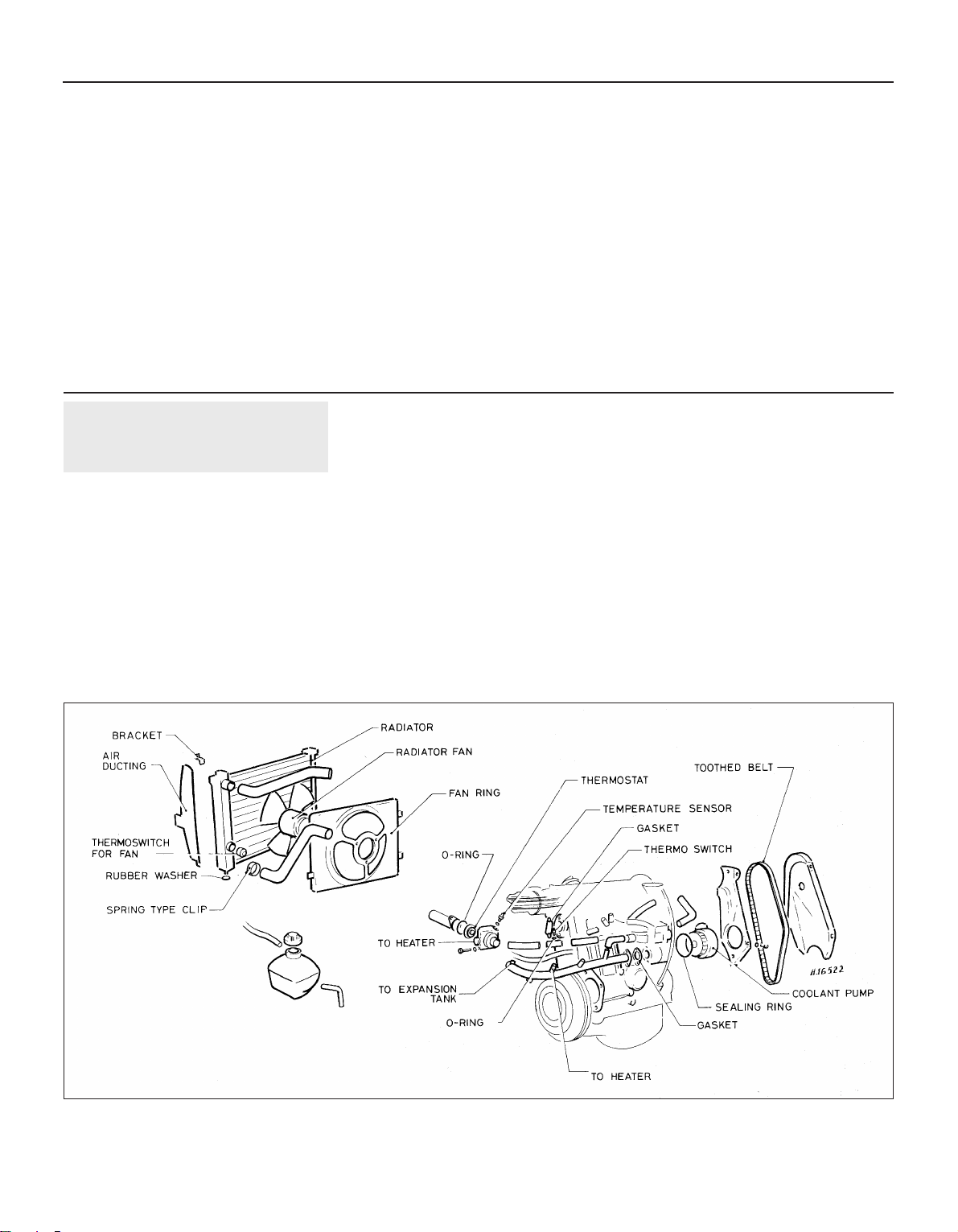
Torque wrench settings Nm lbf ft
All models
Temperature sender unit . . . . . . . . . . . . . . . . . . . . . . . . . . . . . . . . . . . . 10 7
Cooling fan thermo-switch . . . . . . . . . . . . . . . . . . . . . . . . . . . . . . . . . . . 25 18
Radiator . . . . . . . . . . . . . . . . . . . . . . . . . . . . . . . . . . . . . . . . . . . . . . . . . 10 7
1.05 and 1.3 litre
Thermostat housing through-bolts . . . . . . . . . . . . . . . . . . . . . . . . . . . . . 20 14
Thermostat housing-to-pipe bolts . . . . . . . . . . . . . . . . . . . . . . . . . . . . . 10 7
Coolant pump unit . . . . . . . . . . . . . . . . . . . . . . . . . . . . . . . . . . . . . . . . . 10 7
1.6 and 1.8 litre
Coolant pump housing . . . . . . . . . . . . . . . . . . . . . . . . . . . . . . . . . . . . . . 20 14
Coolant pump cover . . . . . . . . . . . . . . . . . . . . . . . . . . . . . . . . . . . . . . . . 10 7
Coolant pump pulley bolts . . . . . . . . . . . . . . . . . . . . . . . . . . . . . . . . . . . 20 14
Thermostat housing to coolant pump . . . . . . . . . . . . . . . . . . . . . . . . . . 10 7
Thermo-switch (inlet manifold preheater):
1.6 and 1.8 litre carburettor . . . . . . . . . . . . . . . . . . . . . . . . . . . . . . . . 10 7
1.8 litre fuel injection . . . . . . . . . . . . . . . . . . . . . . . . . . . . . . . . . . . . . . 30 22
1 General information and
precautions
General information
Cooling and heating systems
The cooling system is of pressurised type
and includes a front mounted radiator, coolant
pump, expansion tank and thermostatically
operated electric cooling fan (see
illustrations).
Coolant circulation through the radiator is
controlled by a thermostat, the location of
which differs according to engine type. On
1.05 and 1.3 litre engines, it is located in a
housing on the rear end of the cylinder head
(left side of vehicle) below the distributor. On
1.6 and 1.8 litre engines, the thermostat is
located in the base of the coolant pump
housing which is mounted low down on the
front of the engine (timing case end).
Fuel-injected engines incorporate an oil
cooler unit which is located between the oil
filter and its mounting bracket.
Cold coolant from the bottom of the
radiator circulates through the bottom hose to
the coolant pump, where the pump impeller
forces it around the cylinder block and head
passages. After cooling the cylinder bores,
combustion surfaces and valve seats, the
coolant reaches the cylinder head outlet and
is returned to the pump via the bypass hoses
when the thermostat is closed. A further
cylinder head outlet allows coolant to circulate
through the inlet manifold and heater matrix
(with heater control on) and it is then returned
to the pump.
When the coolant reaches a predetermined
temperature, the thermostat opens and the
coolant then circulates through the top hose
to the top of the radiator. As the coolant
circulates down through the radiator, it is
cooled by the inrush of air when the vehicle is
in forward motion, supplemented by the
action of the electric cooling fan when
necessary. Having reached the bottom of the
radiator, the coolant is now cooled and the
cycle is repeated.
The electric cooling fan is controlled by a
thermo-switch located in the left-hand side of
the radiator.
3•2 Cooling, heating and air conditioning systems
1081 VW Golf & Jetta
1.0a Cooling system components – 1.05 and 1.3 litre, pre August 1985
Page 93
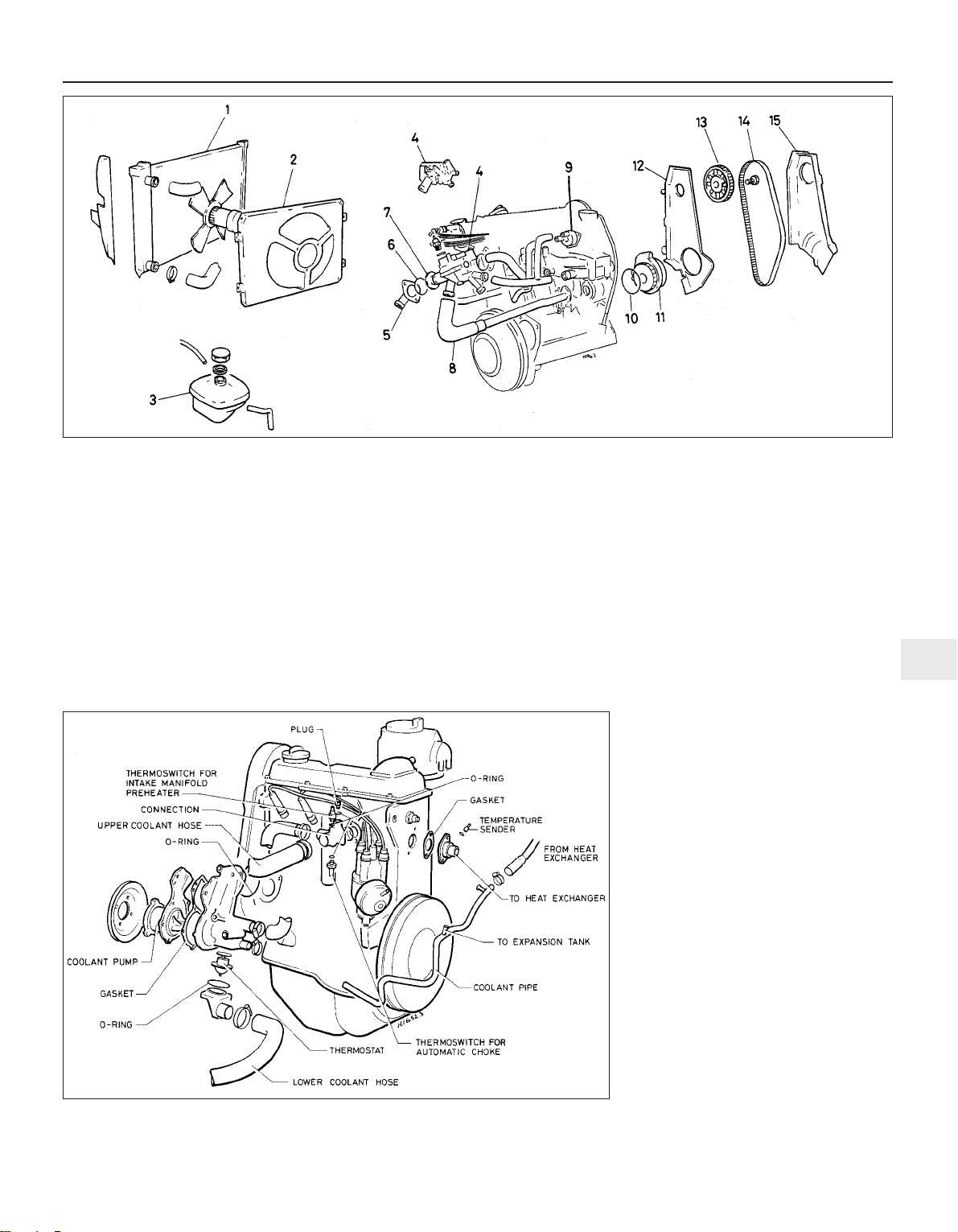
Air conditioning system
The air conditioning unit works on exactly
the same principle as a domestic refrigerator,
having a compressor, a condenser and an
evaporator. The condenser is attached to the
vehicle radiator system. The compressor,
belt-driven from the crankshaft pulley, is
installed on a bracket on the engine. The
evaporator is installed in a housing under the
dashboard which takes the place of the
normal fresh air housing. The housing also
contains a normal heat exchanger unit for
warming the inlet air. The evaporator has a
blower motor to circulate cold air as required.
The system is controlled by a unit on the
dashboard similar to the normal heater control
in appearance.
The refrigerant used is a dangerous
substance in unskilled hands. As a liquid it is
very cold and if allowed to touch the skin will
cause cold burns. As a gas it is colourless and
has no odour. Heavier than air, it displaces
oxygen and can cause asphyxiation if pockets
of it collect in pits or similar workplaces. It
does not burn but even a lighted cigarette
causes it to break down into constituent
gases, some of which are poisonous to the
extent of being fatal.
Precautions
Cooling system maintenance
Do not remove the expansion tank filler cap
or disturb any part of the cooling system
whilst it is hot, as there is a very great risk of
scalding. If the filler cap must be removed
before the system is cool, then the pressure in
the system must first be released. Cover the
cap with a thick layer of cloth, to avoid
scalding, and slowly unscrew the cap until a
hissing sound can be heard. When the hissing
has stopped, then system pressure is
released. Slowly unscrew the cap until it can
be removed. If more hissing sounds are
heard, wait until they have stopped before
unscrewing the cap completely. At all times
keep well away from the filler opening.
If the engine is hot, the electric cooling fan
may start rotating even if the engine is not
running. Be careful to keep hands, hair and
loose clothing well clear of the fan when
working in the engine compartment.
Antifreeze mixture
Antifreeze mixture is poisonous. Keep it out
of reach of children and pets. Never leave
antifreeze lying around, it is fatal if ingested.
Do not allow antifreeze to come in contact
with your skin or the painted surfaces of the
vehicle. Rinse off spills immediately with
plenty of water.
Cooling, heating and air conditioning systems 3•3
3
1081 VW Golf & Jetta
1.0b Cooling system components - 1.05 and 1.3 litre, post August 1985
1 Radiator
2 Fan ring
3 Expansion tank
4 Thermostat housing
5 Cover
6 O-ring
7 Thermostat
8 Hose
9 Automatic choke
10 O-ring
11 Coolant pump
12 Inner timing cover
13 Camshaft sprocket
14 Timing belt
15 Outer timing cover
1.0c Cooling system components – 1.6 and 1.8 litre, carburettor
Page 94
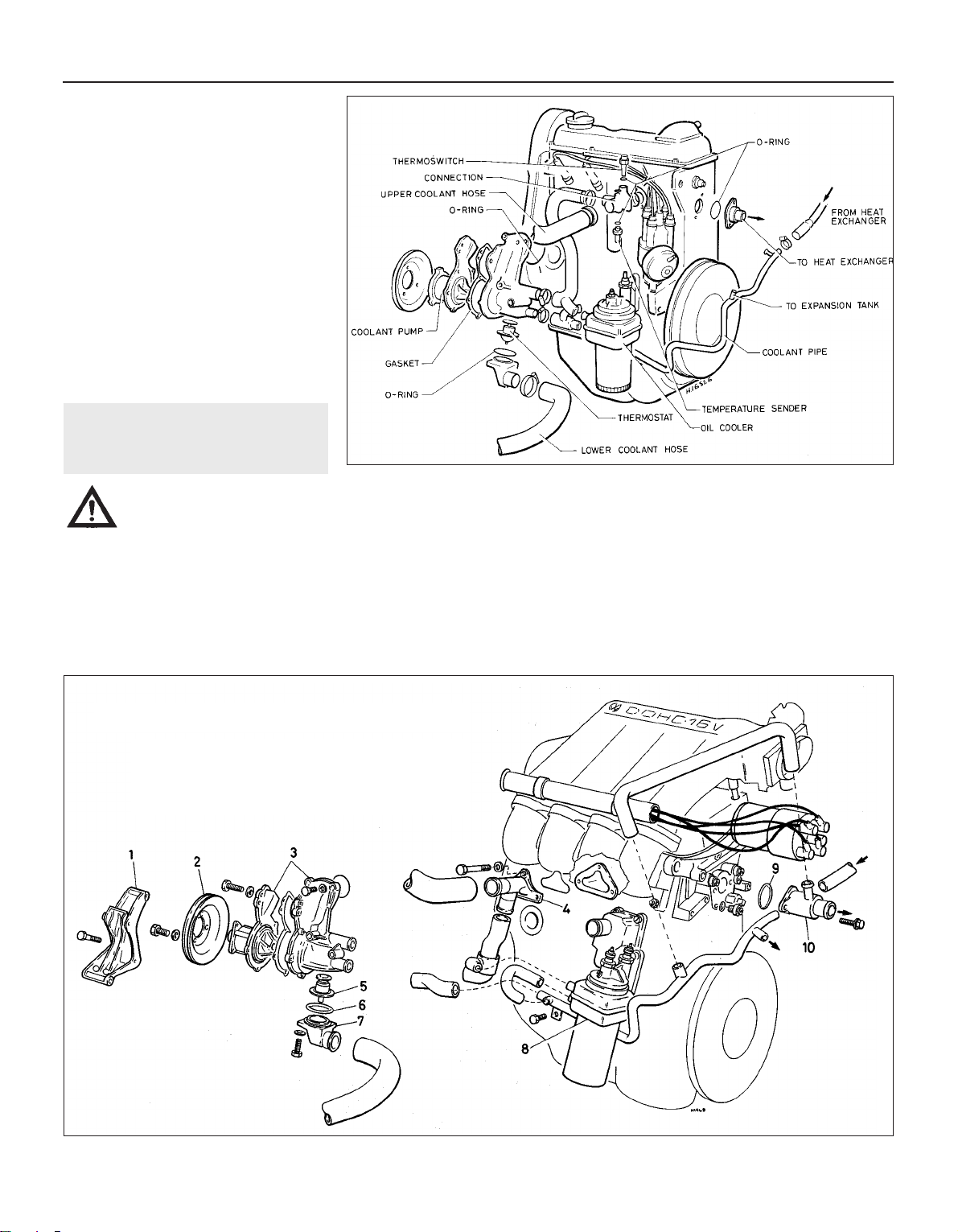
Air conditioning refrigerant
Although the refrigerant is not itself toxic, in
the presence of a naked flame (or a lighted
cigarette) it forms a highly toxic gas. Liquid
refrigerant spilled on the skin will cause
frostbite. If refrigerant enters the eyes, rinse
them with a dilute solution of boric acid and
seek medical advice immediately.
In view of the above points, and of the need
for specialised equipment for evacuating and
recharging the system, any work which
requires the disconnection of a refrigerant line
must be left to a specialist.
Do not allow refrigerant lines to be exposed
to temperatures above 230°F (110°C) - eg.
during welding or paint drying operations. Do
not operate the air conditioning system if it is
known to be short of refrigerant, or further
damage may result.
2 Cooling system - draining,
flushing and filling
2
Warning: Never work on the
cooling system when it is hot.
Take care to avoid any
possibility of scalding
Draining
1 It is preferable to drain the cooling system
when the engine has cooled. If this is not
possible, place a cloth over the expansion
tank filler cap and turn it slowly in an
anti-clockwise direction until pressure starts
to escape.
2 When all pressure has escaped, remove the
filler cap (see illustration).
3 Set the heater controls to maximum heat,
then place a suitable container beneath the
left-hand side of the radiator.
4 Loosen the clip and ease the bottom hose
away from the radiator outlet. Drain the
coolant into the container (see illustrations).
Flushing
5 After some time, the radiator and engine
waterways may become restricted or even
blocked with scale or sediment which can
reduce the efficiency of the cooling system.
When this occurs, the coolant will appear
rusty and dark in colour and the system
should then be flushed. In severe cases
reverse flushing may be required, although if
the correct antifreeze has been in constant
use, this is unlikely.
6 With the coolant drained, disconnect the
top hose from the radiator. Insert a garden
3•4 Cooling, heating and air conditioning systems
1081 VW Golf & Jetta
1.0d Cooling system components – 1.8 litre, fuel injection
1.0e Cooling system components - 16 valve engine
1 Alternator bracket
2 Pulley
3 Coolant pump assembly
4 Outlet elbow
5 Thermostat
6 O-ring
7 Cover
8 Oil cooler
9 O-ring
10 Outlet elbow
Page 95
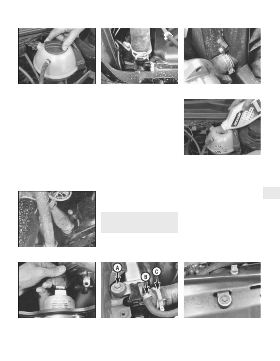
hose and allow the water to circulate through
the radiator until it runs clear from the bottom
outlet. If, after a reasonable period the water
still does not run clear, the radiator can be
flushed with a good proprietary cleaning
agent.
7 Disconnect the heater hose from the
cylinder head outlet and insert a garden hose
in the heater hose. With the heater controls
set at maximum heat, allow water to circulate
through the heater and out through the
bottom hose until it runs clear.
8 In severe cases of contamination the
system should be reverse flushed. To do this,
remove the radiator, invert it and insert a
garden hose in the outlet. Continue flushing
until clear water runs from the inlet.
9 The engine should also be reverse flushed.
To do this, disconnect the heater hose from
the cylinder head outlet and insert a garden
hose in the outlet. Continue flushing until clear
water runs from the bottom hose.
Filling
10 Reconnect all disturbed hoses and check
that the heater controls are set to maximum
heat.
11 Pour the recommended coolant mixture
into the expansion tank until it reaches the
MAX level mark.
12 Refit and tighten the filler cap then run the
engine at a fast idling speed for a few minutes
whilst keeping an eye on the coolant level.
13 Stop the engine and top-up the coolant
level, as necessary, to the MAX mark (see
illustration). Refit the filler cap.
14 After running the engine up to its normal
operating temperature (electric cooling fan
cuts into operation), the coolant level should
be rechecked. When the engine is warm, the
level of the coolant in the reservoir should be
at the MAX level mark. When cool, the coolant
level should be between the MIN and MAX
level marks.
3 Radiator - removal, inspection
and refitting
2
Removal
1 Disconnect the battery negative lead.
2 Drain the cooling system.
3 Disconnect the wiring from the thermoswitch and cooling fan motor (see
illustrations).
4 Disconnect the top hose and expansion
tank hose from the radiator (see illustration).
5 Undo the two retaining bolts (see
illustration) and remove the insulators and L
brackets from the top of the radiator. Note
that the longer bracket is the centre one.
6 Remove the front grille.
7 Remove the two bolts each side at the front
and remove the left and right-hand air ducts.
8 The radiator can now be lifted from the
engine compartment whilst taking care not to
damage the matrix (see illustration).
Inspection
9 Remove the screws and withdraw the
cowling and fan from the radiator.
Cooling, heating and air conditioning systems 3•5
3
2.2 Removing expansion tank cap 2.4a Radiator bottom hose connection -
1.3 litre
2.4b Radiator bottom hose connection -
1.8 litre
2.13 Topping-up engine coolant
3.4 Radiator securing bolt (A) expansion
tank hose connection (B) and top hose
connection (C)
3.3b Detach cooling fan lead connector
3.3a Radiator thermo-switch - 1.8 litre
3.5 Radiator central retaining bolt and
bracket
1081 VW Golf & Jetta
Page 96
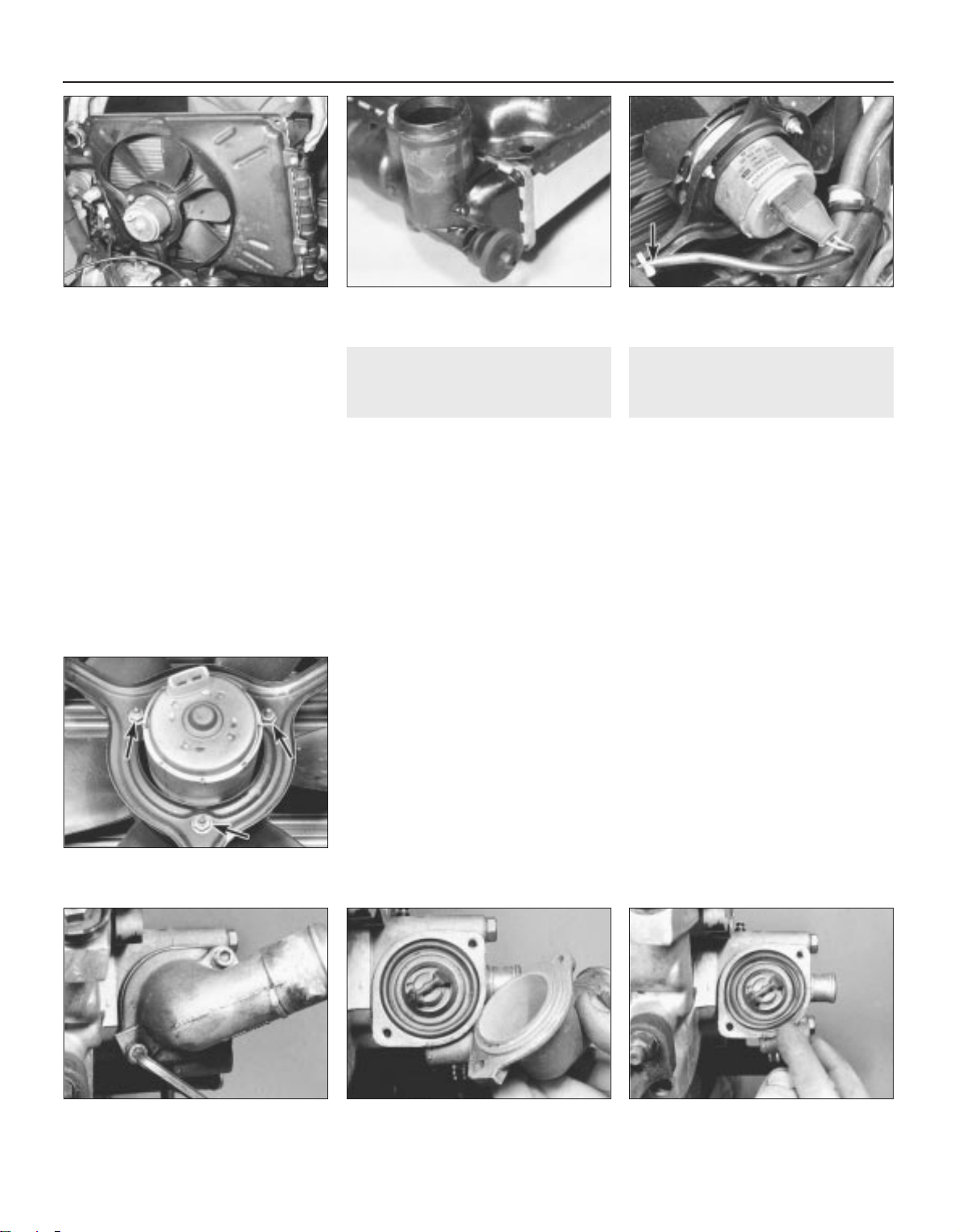
10 Clean the radiator matrix of flies and small
leaves with a soft brush or by hosing. At the
same time check for signs of damage and
coolant leakage.
11 It is not possible to repair this type of
radiator without special equipment.
12 Renew any hoses or clips that are
damaged.
Refitting
13 Refitting is a reversal of removal. If
necessary, renew the radiator lower mounting
rubbers (see illustration).
14 Refill the cooling system.
15 When reconnecting the cooling fan motor
wiring, secure the lead to the cowling web
(see illustration).
4 Cooling fan and motor -
removal and refitting
2
Removal
1 Disconnect the battery negative lead.
2 Disconnect the wiring from the cooling fan
motor and cowling. Note that as from January
1986, the wiring on all new cooling fan motors
obtained from VW incorporates a standardised connector. Where necessary, the old
connector must be cut from the main harness
and the standardised part fitted instead. The
relevant parts are obtainable from a VW
dealer.
3 Remove the retaining bolts and screws and
lift the cowling, together with the cooling fan
and motor, from the radiator.
4 Remove the retaining nuts and withdraw
the cooling fan and motor from the cowling
(see illustration).
5 If necessary, the fan can be separated from
the motor by prising off the clamp washer. On
AEG motors drive out the roll pin. On Bosch
motors remove the shake-proof washer.
Assemble the components in reverse order
using a new clamp washer.
Refitting
6 Refitting is a reversal of removal.
5 Thermostat - removal, testing
and refitting
2
1.05 and 1.3 litre engines
Removal
1 The thermostat is located in the outlet
housing on the left-hand (rear) end of the
cylinder head. To remove it, first drain the
cooling system.
2 Unscrew the bolts and remove the
thermostat cover (see illustrations). Place
the cover with top hose still attached to one
side.
3 Remove the sealing ring (see illustration).
4 Extract the thermostat from the outlet
housing.
Testing
5 To test the thermostat, suspend it with a
piece of string in a container of water.
Gradually heat the water and note the
temperature at which the thermostat starts to
open. Continue heating the water to the
specified fully open temperature then check
that the thermostat has opened by at least the
minimum specified amount. Remove the
thermostat from the water and check that it is
fully closed when cold.
6 Renew the thermostat if it fails to operate
correctly.
7 Clean the thermostat seating and the
mating faces of the outlet housing and cover.
3•6 Cooling, heating and air conditioning systems
3.8 Lifting out radiator and cooling fan
assembly
3.13 Radiator lower mounting rubber 3.15 Secure fan lead with plastic clip
(arrowed)
5.2a Unscrew socket-head bolts . . .
4.4 Cooling fan motor retaining nuts
(arrowed)
5.2b . . . and remove thermostat cover 5.3 Removing thermostat sealing ring
1081 VW Golf & Jetta
Page 97
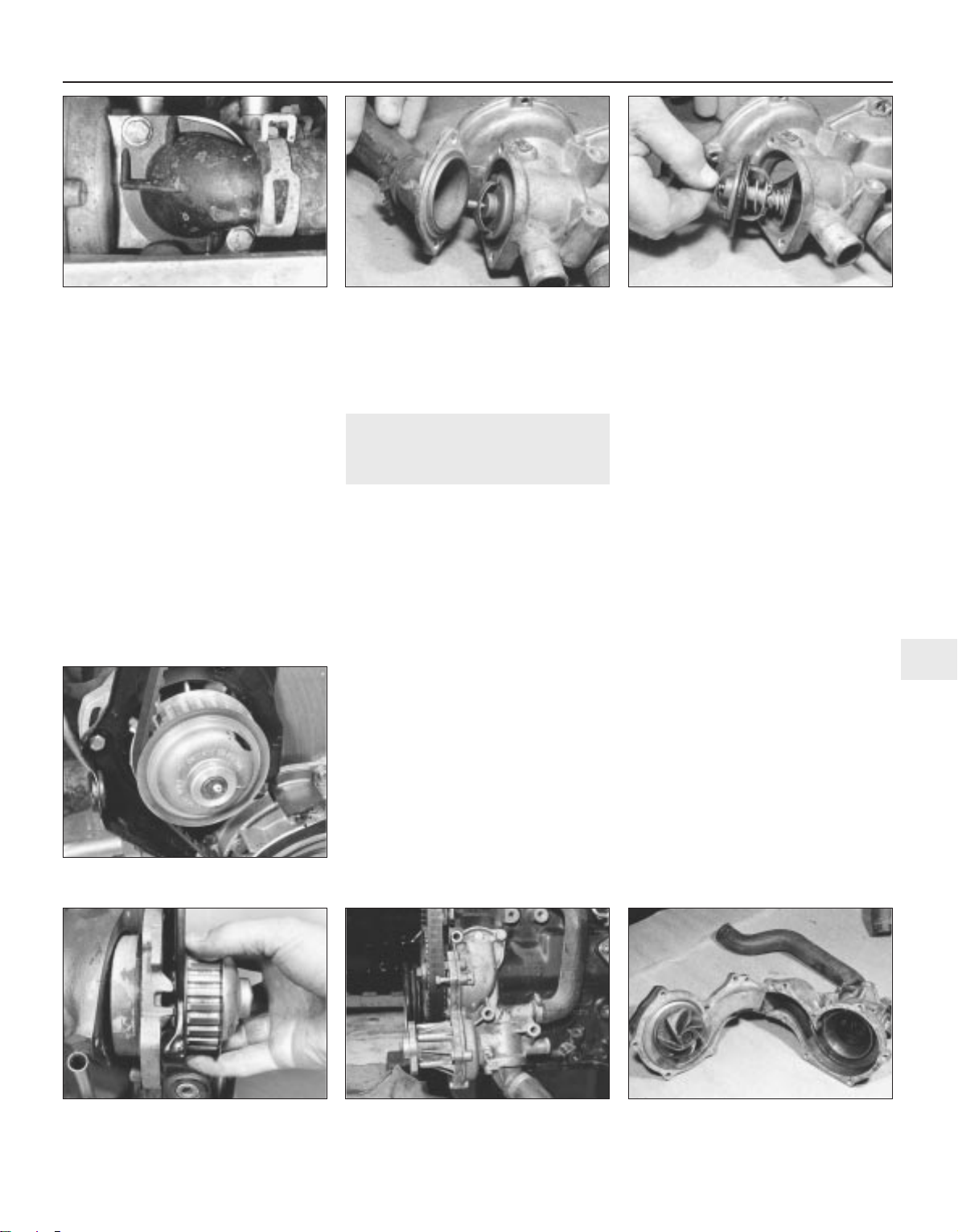
Refitting
8 Refitting is a reversal of removal. Fit a new
sealing ring and tighten the cover bolts to the
specified torque. The breather hole in the
thermostat should face upwards.
9 On completion, refill the cooling system.
1.6 and 1.8 litre engines
Removal
10 The thermostat is located in the bottom of
the coolant pump behind the inlet elbow. To
remove it, first drain the cooling system.
11 Unbolt the inlet elbow from the coolant
pump and remove the seal and thermostat
(see illustrations).
12 Clean the coolant pump and elbow of any
scale or corrosion.
Testing
13 To test the thermostat, proceed as
described in paragraphs 5, 6 and 7.
Refitting
14 Refitting is a reversal of removal
procedure. Always fit a new seal.
15 On completion, refill the cooling system.
6 Coolant pump - removal and
refitting
3
1.05 and 1.3 litre engines
Removal
1 Drain the cooling system.
2 Remove the air cleaner and air ducting and
disconnect the battery negative lead.
3 Unbolt and remove the timing belt cover.
On some later 1.3 litre models, it is necessary
to remove the crankshaft pulley to remove the
lower timing belt cover.
4 Turn the engine with a spanner on the
crankshaft pulley until the timing cover plate
upper retaining bolt is visible through the
camshaft sprocket hole. Unscrew and remove
the bolt.
5 Align the timing marks and release the
timing belt from the coolant pump and
camshaft sprocket (see illustration).
6 Remove the bolts and withdraw the timing
cover plate followed by the coolant pump
(see illustration). Remove the sealing ring.
7 It is not possible to repair the coolant pump
and if faulty, it must be renewed. Clean the
mating faces of the coolant pump and
cylinder block.
Refitting
8 Refitting is a reversal of removal.
9 When fitting a pump which has been
reconditioned by VW, check to see if the
sealing ring groove has been reworked. If it
has, a ‘Y’ will be stamped on the pump
mounting flange indicating that a 5.0 mm
diameter sealing ring should be fitted instead
of the normal 4.0 mm diameter ring. Always fit
a new sealing ring.
10 Correctly tension the timing belt.
11 On completion, refill the cooling system.
1.6 and 1.8 litre engines
Removal
12 Drain the cooling system.
13 Remove the alternator.
14 On models fitted with power steering, it
will be necessary to remove the pump unit
and mounting bracket for access to the
coolant pump.
15 On models equipped with air conditioning,
it will be necessary to move aside the
compressor unit and its mounting. Do not
detach the air conditioning system hoses.
16 Disconnect the three coolant hoses from
the pump, then remove the four bolts holding
the pump to the cylinder block (see
illustration). The pump will probably be stuck
to the block but will come off if tapped gently.
Remove the O-ring with the pump.
17 Remove the pulley and then take out the
eight bolts which secure the bearing housing
and impeller to the coolant pump housing.
The two halves may now be separated (see
illustration). Do not drive a wedge in to break
Cooling, heating and air conditioning systems 3•7
3
5.11a Undo the retaining bolts . . . 5.11b . . . withdraw thermostat elbow . . . 5.11c . . . then extract thermostat and seal
6.6 Withdrawing coolant pump
6.5 Disengage timing belt from coolant
pump sprocket
6.16 Coolant pump location (engine
removed from vehicle) - 1.6 and 1.8 litre
6.17 Two halves of coolant pump -
1.6 and 1.8 litre
1081 VW Golf & Jetta
Page 98
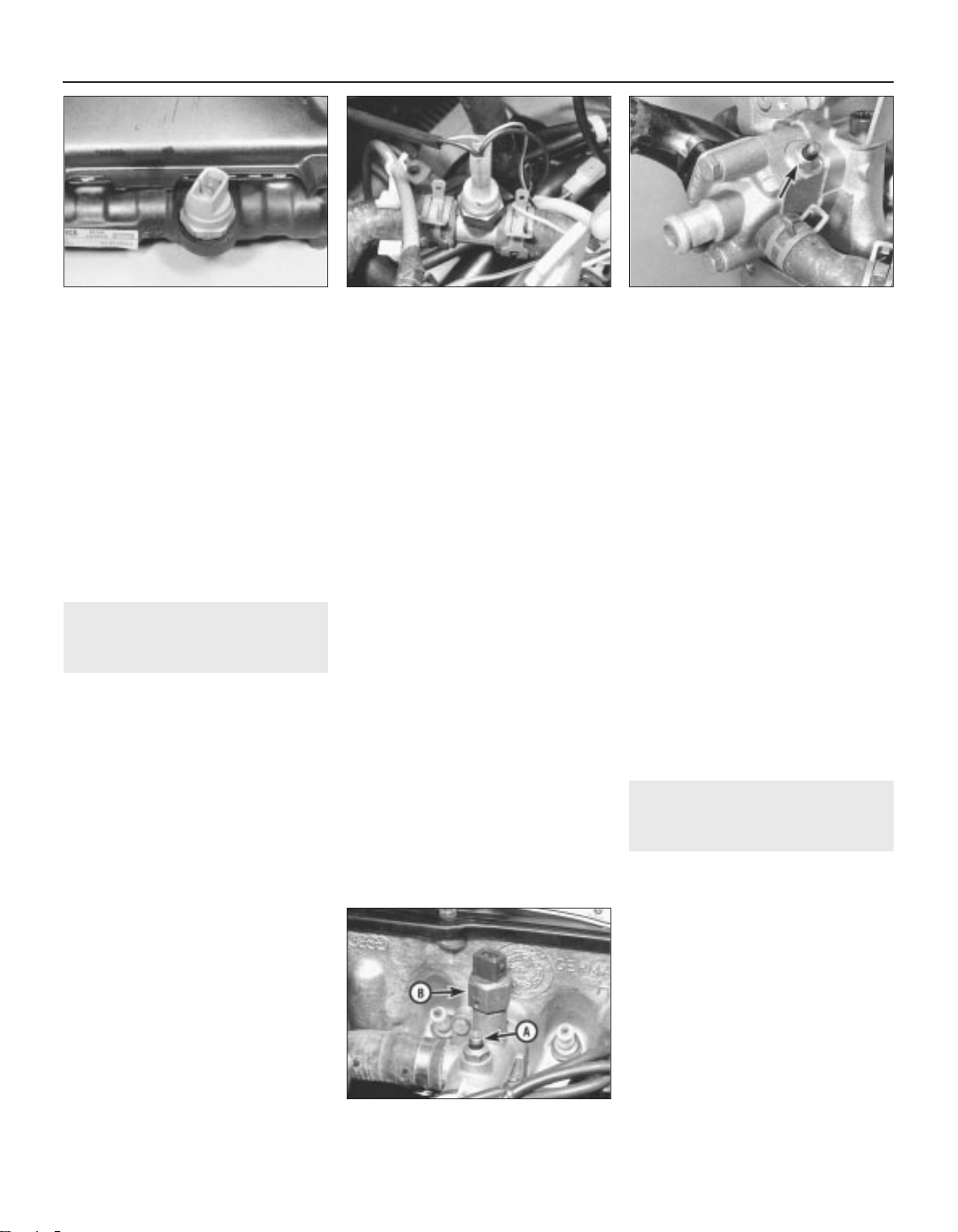
the joint. Clean off the old gasket.
18 Remove the thermostat.
19 The impeller housing and impeller
complete with bearings are serviced as one
part. If coolant is leaking through the bearing,
or the impeller is damaged, the complete
assembly must be renewed.
20 Fit a new gasket using jointing compound,
then fit the two pump halves together and
tighten the bolts evenly.
21 Fit the thermostat.
Refitting
22 Refitting is a reversal of removal. Always
fit a new O-ring.
23 On completion, refill the cooling system.
24 Correctly tension the drivebelt(s).
7 Cooling system electrical
switches - removal, testing
and refitting
2
Cooling fan motor thermoswitch
1 Disconnect the battery negative lead.
2 Drain the cooling system.
3 Unscrew the thermo-switch from the
left-hand side of the radiator and remove the
sealing ring (see illustration). Note that from
September 1985, on fuel injection engines
(except 16V) the switch, located in the bottom
of the radiator, is of a 3-pin type, replacing the
previous 2-pin type. The new switch has two
operation temperature ranges, the first range
operating the coolant fan at normal speed and
the second range operating the fan at boost
speed.
4 To test the thermo-switch, suspend it with a
piece of string so that its element is immersed
in a container of water. Connect the
thermo-switch in series with a 12 volt test
lamp and battery. Gradually heat the water
and note its temperature with a thermometer.
The test lamp should light up at the specified
switch-on temperature and go out at the
specified switch-off temperature. If not, renew
the thermo-switch.
5 Refitting is a reversal of removal. Fit a new
sealing ring and tighten the thermo-switch to
the specified torque.
6 On completion, refill the cooling system.
Cooling fan temperature sensor
7 From March 1986, the cooling fan is also
controlled by a temperature sensor located
between injectors 1 and 2. A time relay is also
incorporated in the wiring circuit to keep the
system functional for 10 to 12 minutes after
switching off the ignition.
Temperature sender
unit/thermo-switches
8 It is not necessary to drain the cooling
system if some form of plug, such as an old
sender unit or rubber plug, is available as a
substitute for the removed switch.
9 Release any pressure in the system by
unscrewing the pressure cap. If the system is
still hot, observe the precautions at the start
of this Chapter. With all pressure released,
retighten the cap.
10 The location of the sender unit or
thermo-switch is dependent on engine type.
In general, they are as follows:
1.05 and 1.3 litre engines
11 The thermo-switch is located in the
intermediate piece in the hoses between the
inlet manifold and thermostat housing (see
illustration).
12 The temperature sensor is located in the
thermostat housing (see illustration).
1.6 and 1.8 litre carburettor engines
13 The temperature sender unit is located in
the heat exchanger hose connecting flange on
the rear of the cylinder head.
14 The thermo-switch (inlet manifold preheater)
is located on the top face of the hose connector
on the spark plug side of the cylinder head.
15 The thermo-switch (automatic choke) is
located in the base of the hose connector on
the spark plug side of the cylinder head.
1.8 litre fuel injection engine
16 The temperature sender unit is located in
the hose connector on the spark plug side of
the cylinder head (see illustration).
17 The thermo-switch is located on the top
face of the hose connector on the spark plug
side of the cylinder head.
1.8 litre 16V engine
18 The temperature sender is located on the
flywheel end of the cylinder block below the
outlet elbow and controls the temperature
gauge.
All engines
19 Disconnect the wiring lead from the
sender unit/switch concerned.
20 Unscrew and remove the sender
unit/switch and plug the aperture.
21 Refitting is the reversal of the removal
procedure. Tighten the sender unit/thermoswitch to the specified torque.
22 On completion, check and if necessary
top-up the cooling system.
8 Heater controls - removal
and refitting
3
Removal
1 Disconnect the battery earth lead.
2 The heater control unit is located in the
centre of the dashboard. It is accessible after
the radio has been removed or, on vehicles
without a radio, the cubby hole.
3 Pull off the control knobs and unclip the
trim panel (see illustrations).
4 Remove the three cross-head screws
holding the control unit and ease it forward
(see illustration).
5 The cables can now be unhooked from the
control unit levers and their outer body
unclipped from the control unit body.
6 If a cable is to be renewed, unhook it from
the control flap at the other end and withdraw
it. For access to the flap control valves, it is
3•8 Cooling, heating and air conditioning systems
7.3 Cooling fan thermo-switch 7.11 Temperature sender unit thermoswitch location - 1.05 and 1.3 litre
7.12 Temperature sensor (arrowed) -
1.05 and 1.3 litre
7.16 Temperature sender unit (A) and
thermo-switch (B) - 1.8 litre, fuel injection
1081 VW Golf & Jetta
Page 99
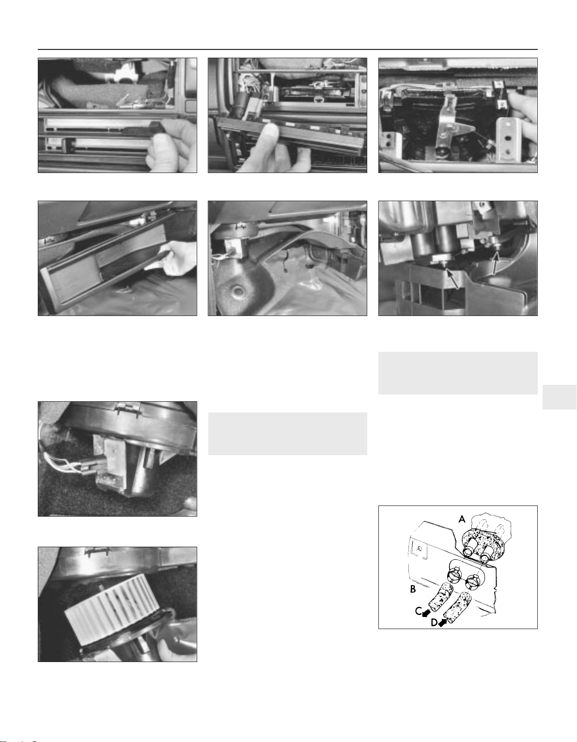
necessary to remove the lower parcel tray on
the passenger side and also the insulation
sheet (see illustrations).
7 It is best to renew the heater cables
completely if the inner cable snaps. In this
way the exact length required is obtained. It is
a good idea to fit new cable clamps also, as
the old ones seem to distort when removed.
Refitting
8 Refitting is a reversal of removal. Ensure
that the cables are correctly routed with no
sharp bends.
9 Heater and fresh air blower
unit - removal and refitting
3
Removal
1 Disconnect the battery earth lead.
2 Remove the parcel shelf and insulation
sheet on the underside of the facia panel on
the passenger side.
3 The blower unit is mounted in the left-hand
corner. Disconnect the wiring multi-connector
(see illustration).
4 Release the retaining tab (carefully) then
twist the blower unit in a clockwise direction
and withdraw it from the housing (see
illustration).
5 The wiring connection plate on the blower
can be levered free by inserting a screwdriver
blade under the retaining tab at the top.
6 If an ohmmeter is available, the thermo
cut-out can be checked as shown.
7 Check that the blower wheel runs freely and
that the air ducts are not blocked.
Refitting
8 Refitting is a reversal of removal.
10 Heat exchanger/fresh air
box - removal and refitting
3
Removal
1 Disconnect the battery earth lead.
2 Remove the centre console.
3 Remove the parcel shelf and insulator panel
on the passenger side.
4 Drain the engine coolant (heater in ON
position).
5 Disconnect the heater coolant hoses at the
bulkhead on the engine compartment side
(see illustration).
Cooling, heating and air conditioning systems 3•9
3
8.3a Pulling free heater/ventilation control
knobs
8.3b Unclip and withdraw trim panel 8.4 Detaching control unit
8.6a Removing parcel shelf . . . 8.6b . . . and insulation sheet
9.3 Blower unit and wiring connection
9.4 Blower unit withdrawal from housing
10.5 Bulkhead coolant hose connections
A Passenger compartment
B Engine compartment
C Return hose
D Supply hose
8.6c Control cable connections to flap
valves at heater distribution box unit
(arrowed)
1081 VW Golf & Jetta
Page 100
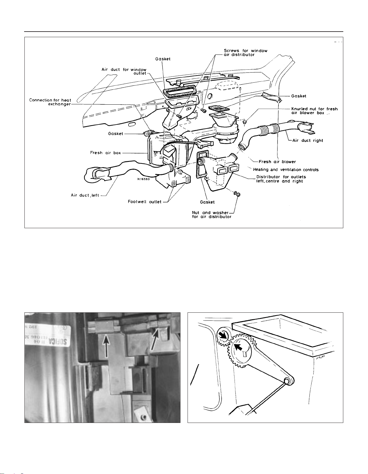
6 Undo the retaining nuts and withdraw the
outlet distributor from the air box,
disconnecting the distributor from the left and
right-hand air ducts as it is withdrawn.
Remove the gasket (see illustration).
7 Disconnect the control cables at the air box
end.
8 Loosen the dash securing screws enough
to enable the air box to be withdrawn and
removed.
9 Release the clips and withdraw the heat
exchanger unit from the air box. Allow for
further coolant drainage from the inlet and
outlet pipes.
10 The housing upper and lower housing
halves can be separated by releasing the
securing clips (see illustration). Once
separated, the flap valves can be removed.
Take care not to split or crack the housings.
Refitting
11 Refitting is a reversal of the removal
procedure. When engaging the control cable
levers, align the index markings on the outer
faces of the segments (see illustration).
Renew the heat exchanger cover gasket and
ensure that the hose connections are securely
made.
12 Before refitting the parcel shelf, top-up
the cooling system and run the engine up to
its normal operating temperature. Operate the
heater and check for any sign of leakage from
the heat exchanger hose connections. Check
that the controls operate in a satisfactory
manner.
3•10 Cooling, heating and air conditioning systems
10.10 Upper-to-lower housing retaining clips (arrowed) 10.11 Align marks to set centre and side outlet flap positions
1081 VW Golf & Jetta
10.6 Heater and ventilation system
components
 Loading...