

Page 1

Owner's manual
ID.4
Edition 10.2020
ID.4 Owner's manual
Owner's manual
ID.4
V1, R1, en_GB
Print status: 12.06.2020
English: 2020.10
Teile-Nr.: 11A012720AB
11A012720AB
Page 2
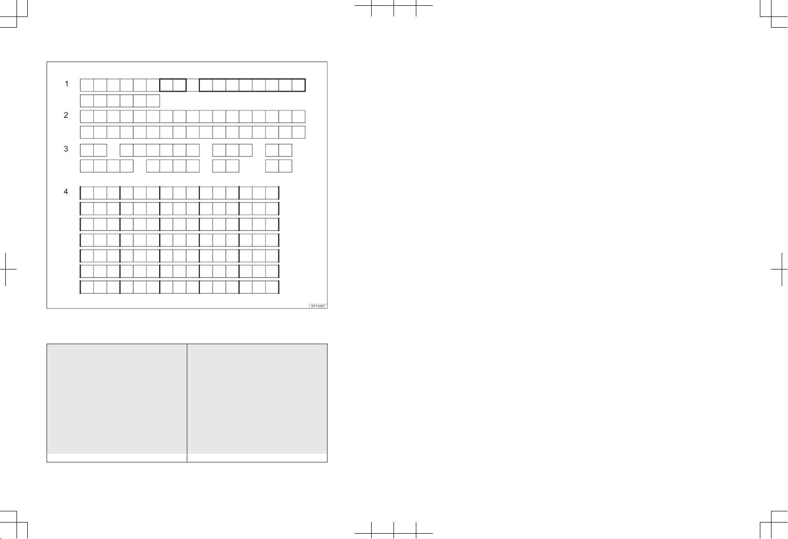
Fig. 1 V
ehicle data sticker. 1: Vehicle identification number; 2: Vehicle type, engine power, gearbox
type; 3: Engine code, gearbox code, paint number, interior equipment; 4: Optional extras, PR numbers
Pre-delivery inspection carried out on: Date of delivery / first registration (whichever
comes first):
Volkswagen dealership stamp Volkswagen dealership stamp
Volkswagen AG works continuously to develop and further impro
ve all vehicle types and
models. Please understand that we must
therefore reserve the right to alter any part
of the vehicle and its equipment or technical
specifications at any time. The data provided
concerning scope of delivery, appearance,
performance, dimensions, weights, standards
and vehicle functions are all correct at the
time of going to print. Some of the equipment and functions described might not yet
be available or may be available only in certain countries. Information about this is available from your local Volkswagen dealership.
The vehicle illustrated on the cover may have
certain items of optional equipment which
are only available at extra cost, or which are
only available in certain markets. Your Volkswagen dealership will be able to inform you
about variations in different countries. Subject to alteration and amendment. No legal
commitment may be inferred from the information, illustrations or descriptions in this
manual.
No part of this manual may be reprinted, reproduced or translated without the written
permission of Volkswagen AG.
All rights under the laws of copyright are expressly reserved by Volkswagen AG. Subject
to alteration and amendment.
© 2020 Volkswagen AG
Page 3
Thank you for choosing Volkswagen
11A012720AB
By purchasing this Volkswagen, you have become the owner of a vehicle fitted with the most
up-to-date technology and a multitude of con
Before using your vehicle for the first time, please read and observe the information in this
owner's manual. It will quickly help you to become familiar with your vehicle and all of its
functions as well as making you aware of dangers to yourself and others and of how these
dangers can be avoided.
If you have any further questions about your vehicle, or if you think that the vehicle wallet has
not covered everything, please get in touch with your Volkswagen dealership. They will always
be happy to deal with your questions, suggestions or problems.
We hope you enjoy driving your new vehicle. Happy motoring.
venience functions for your use and enjoyment.
WARNING
Please observe the important safety instructions for use of child restraint systems on the front
passenger seat → page 57
11A012720AB
Page 4

Table of Contents
Vehicle overviews
— Front view 7
— Rear view 8
— Driver door 9
— Driver side 10
— Centre console 13
— Front passenger side 14
— Controls and displays in the roof 14
Driver information
— Symbols in the instrument cluster 15
— Instrument cluster 18
— Infotainment system controls and
displays 30
— ID. Light 31
Safety
— General notes 32
— Sitting position 34
— Seat belts 36
— Proactive occupant protection system 45
— Airbag system 47
— Safe transport of children 57
— In an emergency 66
Opening and closing
— Vehicle key 73
— Keyless locking and starting system
“Keyless Access” 75
— Doors and central locking button 77
— Anti-theft alarm 83
— Interior monitoring system and anti-
tow alarm 83
— Boot lid 84
— Windows 89
Steering wheel
— Adjusting the steering wheel position 92
Seats and head restraints
— Front seats 93
— Rear seats 96
— Head restraints 98
— Seat functions 100
Lights
— Turn signals 102
— Vehicle lighting 103
— Interior lighting 111
Vision
— Wipers 112
— Mirrors 115
— Protection from the sun 118
Heating and air conditioning system
— Heating, ventilation, cooling 120
— Stationary air conditioning 127
Driving
— Notes on driving 129
— Activating and deactivating the
ehicle’s drive system 137
v
— Selecting a position 140
— Steering 142
— Driving profile selection 143
Driver assist systems
— Cruise control system 145
— Speed limiter 147
— Speed limiter with predictive control 149
— Adaptive Cruise Control (ACC) 151
— Predictive cruise control 156
— Area monitoring system (Front Assist) 159
— Lane keeping system (Lane Assist) 165
— Travel Assist 168
— Semi-automatic vehicle control in
a medical emergency (Emergency
Assist) 171
— Lane change system (Side Assist) 172
Parking and manoeuvring
— Parking 176
— Electronic parking brake 177
— General information about the parking
systems 179
— Park Distance Control 184
— Rear view camera system 185
— Area View 187
— Rear Traffic Alert 188
2
Table of Contents
Page 5

— Brake support systems 189
Practical equipment
— Stowage areas 193
— Sockets 193
Data transfer
— Cybersecurity 195
— System update 196
— Car2X communication 198
— Volkswagen We Connect Start 200
— Privacy settings 204
— User administration 205
— Activating functions (We Upgrade) 206
— Wi-Fi hotspot 207
— App-Connect 210
— Cable and wireless connections 215
Infotainment system
— Getting started 217
— Voice control 228
— Radio mode 231
— Media mode 234
— Navigation 238
— Mobile phone interface 246
Transporting items
— Stowing luggage and loads 254
— Luggage compartment cover 255
— Luggage compartment floor 255
— Partition 257
— Luggage compartment equipment 259
— Roof carrier 262
— Towing a trailer 264
High-voltage battery
— Safety notes 273
— Care instructions for the high-voltage
battery 275
— Charging settings in the Infotainment
system 276
— Charging the high-voltage battery 279
— Charging cable 287
If and when
— Vehicle toolkit 292
— Wiper blades 293
— Exterior lighting 295
11A012720AB
— Changing fuses 296
— Jump starting 301
— Towing 304
Checking and refilling
— In the front compartment 309
— Service fluids and consumables 313
— Washer fluid 314
— Coolant 315
— Brake fluid 318
— 12-volt vehicle battery 320
Wheels and tyres
— Tyre monitoring system 325
— Useful information about wheels and
tyres 328
— Hubcaps 341
— Changing a wheel 343
— Breakdown set 348
Maintenance
— Service 353
— Vehicle care 355
— Accessories, modifications, repairs and
renewal of parts 362
Customer information
— Warranty 366
— Guarantee for high-voltage batteries
in electric and hybrid v
ehicles 366
— Data storage and services 366
— Event data recorder 369
— Information stickers and plates 370
— Fluids in the air conditioning system 371
— Infotainment system and antennas 371
— Component protection 372
— Information in accordance with the EU
Chemicals Regulation REACH 372
— Disposal of used batteries and
electronic de
vices 372
— Declaration of conformity 372
— Third party copyright law information 373
— Returning and scrapping end-of-life
vehicles 373
— Information about vehicles with N1
approval (light commercial vehicle) 373
— Declaration of conformity for radio
systems in Europe 374
Table of Contents
3
Page 6

— Declaration of conformity for radio
systems in countries outside of Europe 380
Technical data
— Notes on technical data 387
— Vehicle identification number 387
— Type plate 389
— Safety certificate 389
— Vehicle data sticker 389
— Dimensions 390
— Electric drive 391
Abbreviations used 393
Index 395
4 Table of Contents
Page 7

About this owner’s manual
This owner's manual is valid for all model
types and v
owner's manual describes all equipment and
models without indicating whether the
equipment is optional or specific to the model type. This means that your vehicle may not
have some of the equipment described, or it
may only be available in certain markets. The
scope of equipment fitted in your vehicle can
be found in the sales documentation and you
can contact your Volkswagen dealership for
further information.
A passenger car is described in this owner’s
manual.
Depending on the market-specific vehicle approval, the model version may also be a light
commercial vehicle.
All data in this owner's manual correspond to
the information available at the time of going
to print. Because the vehicle is constantly being developed and further improved, there
may be differences between your vehicle and
the data in this owner's manual. No discrepancy in data, illustrations or descriptions shall
form the basis for any legal claim.
Please ensure that the complete vehicle wallet is always in the vehicle if you lend or sell
the vehicle to someone else. Volkswagen also
recommends restoring the Infotainment system to factory settings in order to delete all
personal data.
— An alphabetical index is included at the
— A list of abbreviations at the end of the
— Directions and positions such as left, right,
ersions of your Volkswagen. The
end of this manual.
manual explains the abbreviations used.
front and rear are normally relative to the
vehicle's direction of travel, unless otherwise indicated.
— Illustrations help with orientation and
should be regarded as a general guide.
— This owner's manual was written for left-
hand drive vehicles. In right-hand drive ve-
hicles the controls may sometimes differ
from those displayed in illustrations or described in the text.
— Values given in miles instead of kilometres
or mph instead km/h refer to the countryspecific instrument clusters or Infotainment systems.
— Short definitions appear in a different col-
our before some sections of this manual.
They provide a summary of the function
and use of a system or feature. More detailed information about the features, conditions and limitations of systems and
equipment can be found in the relevant
sections.
— Critical safety issues or any technical
changes that may be made to the vehicle
after publication of this booklet are contained in a supplement that is included
with the vehicle wallet.
— For better legibility, the male form of ad-
dress is used. However, this refers to all
sexes equally. The shortened linguistic
form is used for editorial reasons and does
not represent a value judgement.
Booklets in the vehicle wallet:
— Owner's manual
— Supplement (optional)
— Other supplements
11A012720AB
About this owner’s manual 5
Page 8
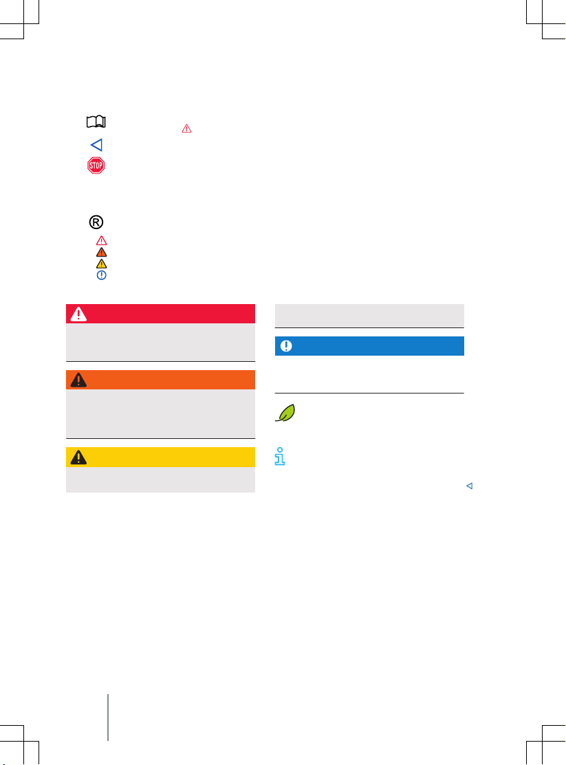
Description of symbols
Refers to a section within a chapter that contains important information and
ety notes
saf
Indicates the end of a section.
Indicates situations in which the vehicle must be stopped as quickly as possible.
TM The symbol means “Trademark” and identifies an recognised but not (yet) offi-
cially registered mark. Howe
a waiver of the rights concerning any term.
The symbol indicates a registered mark. However, the absence of this symbol
→
→
→
→ Cross reference to potential risks of damage to property in the same section or
does not constitute a waiv
Symbols like these refer you to warnings within the same section or on a given
page. They draw your attention to possible risks of accident or injury and e
how they can be avoided.
on the page specified.
DANGER
Texts with this symbol indicate dangerous
situations which will lead to fatal or se
injuries if you do not observe the warning.
WARNING
Texts with this symbol indicate dangerous
situations which could lead to fatal or se-
ere injuries if you do not observe the
v
warning.
CAUTION
Texts with this symbol indicate dangerous
situations which could lead to slight or me-
that should always be observed.
ver, the absence of this symbol does not constitute
er of the rights concerning any term.
dium injuries if you do not observe the
warning.
vere
NOTICE
Texts with this symbol indicate situations
which could cause v
not observe the warning.
Texts with this symbol contain additional inf
the environment.
Texts with this symbol contain additional information.
ehicle damage if you do
ormation on the protection of
xplain
6 Description of symbols
Page 9

Vehicle overviews
ront view
F
Fig. 2 Ov
1
2
3
4
5
6
7
8
11A012720AB
erview of vehicle from front.
Door handles .................................................................................................................. 77
Headlights ...................................................................................................................... 295
Sensors for assist systems ........................................................................................... 358
Behind a cover: mounting for towing eye .................................................................. 304
Behind a cover: radar sensor for assist systems ........................................................ 358
In the Volkswagen badge: camera for assist systems ............................................... 358
Bonnet release lever with bonnet space underneath ............................................... 312
Windscreen:
— with vehicle identification number ........................................................................ 387
— with windscreen wiper ............................................................................................ 112
— with camera window for assist systems ................................................................ 358
— with rain/light sensor positioned near the interior mirror .................................. 114, 358
Front view 7
Page 10

Rear view
Fig. 3 Ov
erview of vehicle from rear.
1
Roof aerial ...................................................................................................................... 371
2
High-level brake light
3
Rear window:
— with rear window heating ....................................................................................... 120
— with rear window wiper .......................................................................................... 112
— with window aerial ................................................................................................... 371
4
Number plate light ........................................................................................................ 295
5
Area:
— of the button for opening the boot lid ................................................................... 84
— of the camera for parking systems ......................................................................... 185, 358
6
Sensors for assist systems ........................................................................................... 358
7
Behind a cover: mounting for towing eye .................................................................. 304
8
Behind the bumper: radar sensor for assist systems ................................................ 358
9
Jacking points ................................................................................................................ 343
10
Tail light clusters and reflectors .................................................................................. 295
11
Charging socket flap ..................................................................................................... 279
12
Exterior mirrors ............................................................................................................. 117
— with “lane change system” display ........................................................................ 172
8 Vehicle overviews
Page 11

Driver door
Fig. 4 Driv
1
2
3
4
5
6
7
8
9
11A012720AB
er door (left-hand drive vehicles): controls (mirrored for right-hand drive vehicles).
Door release lever
Central locking system indicator lamp ....................................................................... 78
Touch control for deactivating the rear electric window buttons and activating
the electric childproof lock .......................................................................................... 89, 81
Touch control for locking and unlocking the vehicle ................................................ 79
Rotary knob for exterior mirror adjustment and functions ...................................... 117
Buttons for operating the electric windows .............................................................. 89
Release lever for bonnet ........................................................................................
312
Button for opening the boot lid ................................................................................... 84
Stowage compartment:
— with bottle holder
— with stowage facility for high-visibility waistcoat ............................................... 68
Driver door 9
Page 12

Driver side
Fig. 5 Ov
10
erview of the driver side (left-hand drive vehicles).
Vehicle overviews
Page 13
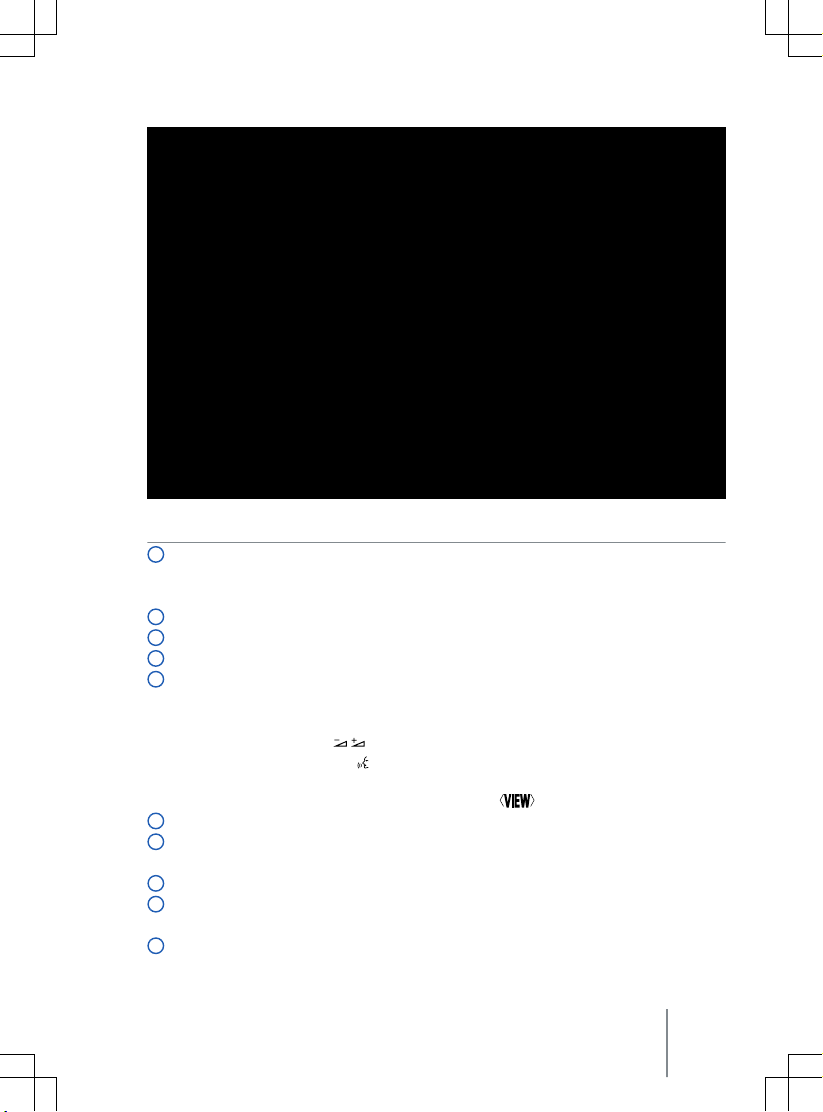
Fig. 6 Ov
1
2
3
4
5
6
7
8
9
10
11A012720AB
erview of the driver side (right-hand drive vehicles).
Touch panel:
— for light functions ..................................................................................................... 103
— for window heating and window ventilation ........................................................ 120
Vent ................................................................................................................................. 120
ID. Light (light strip between windscreen and dash panel) ...................................... 31
Turn signal and main beam lever ................................................................................ 102, 105
Touch controls of the multifunction steering wheel:
— for driver assist systems .......................................................................................... 145
— for audio, navigation ................................................................................................ 217
— for volume adjustment
— for activating voice control (function may not be available depending on
v
ehicle equipment) ................................................................................................... 228
— for switching between the views of the ID. Cockpit
.................................
Horn
ID. Cockpit ...................................................................................................................... 18
— with warning and indicator lamps and gear indicator ......................................... 15
Head-up display ............................................................................................................ 21
Position switch .............................................................................................................. 140
— with button for electronic parking brake ............................................................... 177
Lever for wipers and washers ...................................................................................... 112
Driver side 11
18
Page 14
11
Infotainment system .................................................................................................... 217
12
Touch panel:
— for switching the Infotainment system on and off .............................................. 222
— for setting temperature of air conditioning system or heating and fresh air
system ....................................................................................................................... 120
— for volume adjustment
13
Touch control for switching the hazard warning lights on and off
14
Touch panel:
....................
— for the air conditioning system, heating and fresh air system ............................ 120
— for driving profile selection ..................................................................................... 143
— for driver assist systems .......................................................................................... 145
— for assist systems for parking and manoeuvring ..............................................
15
Starter button ................................................................................................................ 137
16
Pedals ............................................................................................................................. 129
17
Location of the driver front airbag .............................................................................. 47
18
Lever for adjusting the steering column position ...................................................... 92
66
176
12 Vehicle overviews
Page 15

Centre console
Fig. 7 Ov
centre console.
1
2
3
11A012720AB
erview of the lower section of the
Card holder
Stowage compartment
— with removable drink holder
— with contact area for the vehicle key for emergency start ................................. 139
Under a cover: stowage compartment
— with USB ports .......................................................................................................... 215
— with phone interface ................................................................................................ 246
Centre console 13
Page 16
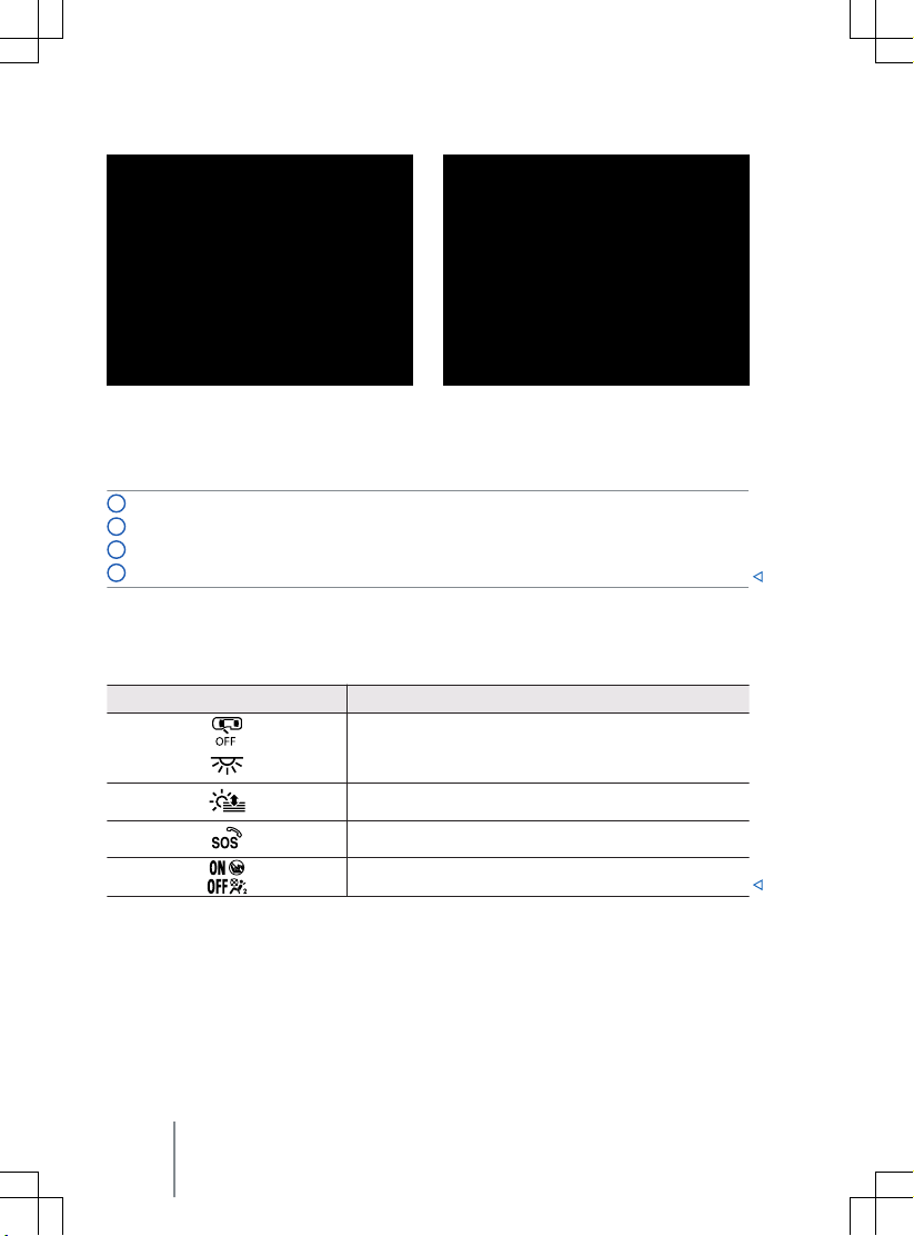
Front passenger side
Fig. 8 F
ront passenger side (left-hand drive vehicles): overview of dash panel (mirrored for
right-hand drive vehicles).
1
Vent ................................................................................................................................. 120
2
Glove box with button for opening
3
Location of front passenger front airbag in the dash panel ..................................... 47
4
Key switch for switching off the front passenger front airbag ................................ 53
Fig. 9 With open front passenger door (lefthand driv
e vehicles): key-operated switch in the
dash panel (mirrored for right-hand drive vehicles).
Controls and displays in the roof
Symbol Meaning
Touch panels for interior and reading lights → page 111.
Touch panel for sun blind in the glass roof → page 119.
Button for emergency call service → page 69.
Indicator lamp for the front passenger front airbag switchoff function → page 47.
14 Vehicle overviews
Page 17
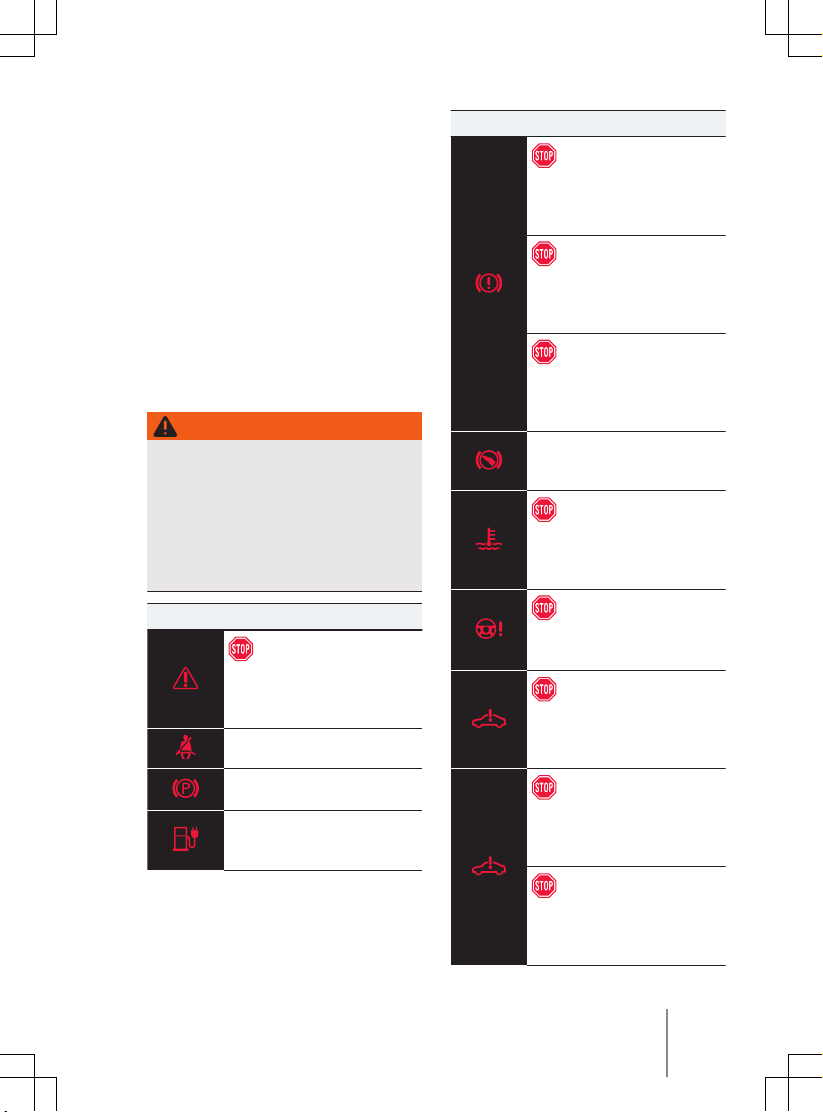
Driver information
Symbol Meaning
Symbols in the instrument cluster
The warning and indicator lamps can light up
individually or in combination and indicate
warnings, faults or certain functions. Some
warning and indicator lamps light up when
the ignition is switched on and should go out
after a while.
or details on indicator lamps that light up in
F
the light switch, see Chapter “Lights”
→ page 103.
WARNING
Failure to observe illuminated warning
lamps and te
vehicle breaking down in traffic, and can
cause accidents and serious injury.
Never ignore any illuminated warning
·
lamps or text messages.
Stop the vehicle as soon as possible and
·
when safe to do so.
Symbol Meaning
xt messages can lead to your
Do not drive on!
Central warning lamp
→ page 24
Fasten seat belt → page 37
Electronic parking brake
→ page 177
Exhaustive discharge of the
high-
voltage battery
→ page 285
Do not drive on!
Brake system fault → page 134,
→ page 178
Do not drive on!
Electromechanical brake serv
failure → page 191
Do not drive on!
Low brake fluid le
→ page 319
Take over control of the vehicle
and be prepared to brake.
→ page 151
Do not drive on!
ault in engine coolant system
F
→ page 318
Do not drive on!
Steering fault → page 143
Do not drive on!
ault in high-voltage system
F
→ page 285
Do not tow vehicle!
oltage system overhea-
High v
ted → page 305
vel
o
11A012720AB
Do not drive on!
Electric driv
→ page 142
Symbols in the instrument cluster 15
e overheated
Page 18

Symbol Meaning
Do not drive on!
volt vehicle battery
12→ page 323
High-voltage battery empty
ehicle operation not possi-
— v
ble → page 136, → page 136
Health risk! Open windows! CO²
concentration to high
→ page 126
Collision warning → page 161
Take over steering immediately
→ page 170
Intervention by proactive occupant protection system
→ page 46
Central warning lamp
→ page 24
Fault in airbag or belt tensioner
system → page 50
Airbag or belt tensioner system
switched off with diagnostic
tool → page 50
Range calculation fault
→ page 285
Front passenger front airbag
switched off → page 50
Front passenger front airbag
switched on → page 50
Emergency call system fault
→ page 71
Emergency call system operation restricted → page 71
Electronic parking brake fault
→ page 178
Check the brake pads
→ page 134
Symbol Meaning
Flashes: Electronic Stability
Control (ESC) or traction control system (TCS) regulating
→ page 192
Lit: Electronic Stability Control
(ESC) faulty → page 192
Traction control system (TCS)
switched off → page 192
ESC Sport switched on
→ page 192
Anti-lock brake system (ABS)
fault → page 191
Travel Assist fault → page 170
Vehicle lighting failure
→ page 111
Rear fog light switched on
→ page 104
Health risk! Open windows! CO²
concentration too high
→ page 126
Air conditioning system not
working properly or CO² concentration cannot be measured
→ page 126
Rain/light sensor fault
→ page 111, → page 115
Fault in wipers → page 114
Washer fluid level too low
→ page 114
Fault in steering → page 143
16 Driver information
Page 19
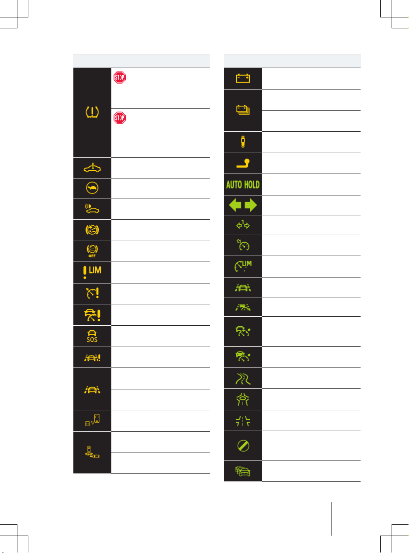
11A012720AB
Symbol Meaning
Do not drive on!
Low tyre pressure → page 327
Do not drive on!
ault in the Tyre Pressure Mon-
F
itoring System → page 327
Fault in electric drive system
→ page 139, → page 142
Reduced power → page 137
Electronic engine sound fault
→ page 140
Front Assist not available
→ page 165
Front Assist switched off
→ page 164
Speed limiter not available
→ page 148
Fault in the Cruise Control System → page 147
Adaptive Cruise Control (ACC) is
vailable → page 156
not a
Emergency Assist not available
→ page 172
Lane keeping system (Lane Assist) not a
Lane keeping system (Lane Assist) is regulating → page 167
Emergency Assist intervention
→ page 171
Fault in the lane change system
(Side Assist) → page 174
Rear Traffic Alert braking interv
ention → page 189
Rear Traffic Alert fault
→ page 189
vailable → page 167
Symbol Meaning
12-volt vehicle battery
→ page 323
Low charge level of the high-
oltage battery → page 285
v
High-voltage battery empty
→ page 285
Adaptive chassis control fault
→ page 144
Ball head of the towing bracket
is not locked → page 273
The vehicle is held stationary
→ page 179
Turn signals → page 110
Trailer turn signal → page 111
Cruise control system switched
on, control activ
Speed limiter active
→ page 147
Lane Assist active → page 167
Travel Assist active → page 169
The ACC is regulating, no vehicle detected in front
→ page 154
The ACC is regulating, vehicle
in front detected → page 154
Speed regulation due to the
road layout → page 158
Speed regulation due to
a roundabout → page 158
Speed regulation due to a junction → page 158
Speed regulation due to cancellation of the speed limit
→ page 158
Speed regulation due to the
end of a traffic jam → page 158
e. → page 145
Symbols in the instrument cluster 17
Page 20
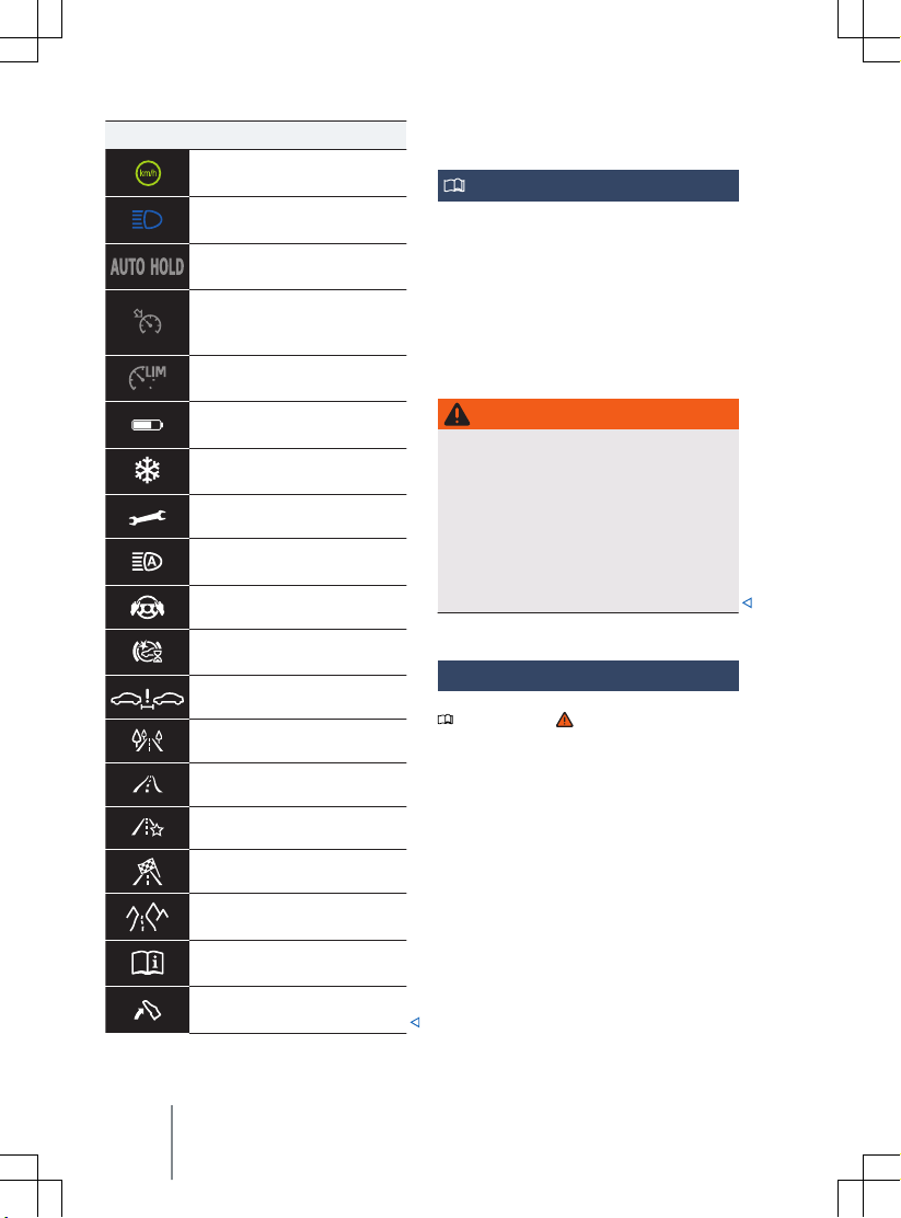
Symbol Meaning
Speed regulation due to speed
limit → page 150, → page 158
Main beam or headlight flasher
→ page 105
Auto Hold function switched on
→ page 179
Cruise control switched on,
system control not activ
→ page 145
The speed limiter is not active
→ page 147
Charge level of high-voltage
battery → page 19
Outside temperature colder
than +4°C (+39°F) → page 23
Service due → page 30
Main-beam control active
→ page 106, → page 107
Take over steering → page 170
Front Assist is starting up
→ page 165
Distance warning → page 161
Eco driving profile → page 144
Instrument cluster
Introduction to the topic
When you activ
after the 12-volt vehicle battery has been totally discharged, replaced or after a jump
start, you may find that system settings, such
as personal convenience settings and pro-
e.
gramming, have been changed or deleted.
Check and correct the settings as necessary
once the 12-volt vehicle battery has been
sufficiently charged.
WARNING
Accidents and injuries can occur if the driver is distracted.
Ne
·
while the vehicle is in motion.
Any settings for the instrument cluster
·
display and displays in the Infotainment
system should be made only when the
vehicle is stationary in order to reduce
the risk of accidents and serious injuries.
ID. Cockpit
Please refer to at the start of the chap-
ter on page 18.
ate the vehicle’s drive system
ver operate the instrument cluster
Comfort mode → page 144
Individual mode → page 144
Sport mode → page 144
Traction driving profile
→ page 144
Reference to information in the
v
ehicle wallet → page 24
Take your foot off the accelerator → page 28
18 Driver information
Fig. 10 ID. Cockpit in the dash panel.
Page 21
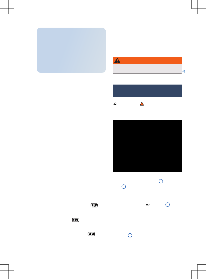
The ID. Cockpit is a digital instrument
cluster with a high-resolution LC colour
display. By selecting diff
tion profiles, displays from the driver assist systems and other displays can be
shown in addition to the digital speedometer. The term “digital instrument
cluster” is used below for the ID. Cockpit.
Views in the display area
The digital instrument cluster can display the
following views → Fig. 10:
Summary
Basic
Driver assist systems
Navigation
The upper display area shows situationdependent pop-ups, for example.
The amount and scope of the displayed information may differ depending on the vehicle
equipment.
Setting views
The different views provide a better overview
of the driving data, navigation or information
on the driver assist systems.
The “driver assist systems” view and “navigation” view can be selected with the
ton on the multifunction steering wheel.
—
—
11A012720AB
Before activation of the vehicle’s
drive system: display with information on mileage, charge level and
range.
Driving displays with information on
driver assist systems, speed and navigation.
assist systems and speed. The navigation context is hidden.
Display with route guidance and
speed information. The graphic view
of the driver assist systems is hidden.
To change to the “Navigation” view, press
the right area of the
from right to left.
To change to the “Driver assist systems”
view, press the left area of the
ton or swipe from left to right.
erent informa-
Display of active driver
but-
button or swipe
but-
Event in the digital instrument cluster
ormation and warnings are shown as an
Inf
event in the digital instrument cluster. The
event display appears in the digital instrument cluster from above and is hidden again
after some time.
WARNING
Accidents and injuries can occur if the driver is distracted.
Charge level and range in the
digital instrument cluster
Please refer to at the start of the chap-
ter on page 18.
Charge level display
Fig. 11 In the digital instrument cluster: charge
vel of the high-voltage battery
le
range 2 .
The current charge le
battery is displayed in the digital instrument
cluster by the symbol
fill level of the battery symbol changes with
the charge level.
Range display
The vehicle range is specified in kilometres
(km) or miles (mi), depending on the setting
→ Fig. 12 2 .
1 and vehicle
vel of the high-voltage
→ Fig. 12 1 . The
Instrument cluster 19
Page 22

The displayed value is calculated and updated
depending on the driving style and ambient
conditions. The range can theref
even for a fully charged high-voltage battery.
Reserve range
Fig. 12 In the digital instrument cluster: range
e capacity display.
and reserv
1
Charge level and range.
2
Reserve capacity warning level 1 and
range.
3
Reserve capacity warning level 2 and
range.
When the red reserve range of the high-voltage battery is reached, the symbol is displayed together with a colour percentage v
ue → Fig. 12
Warning le
Yellow
Red
Charge the high-voltage battery as soon as
possible to prevent the vehicle from breaking
down →
3 → .
vels for the reserve range:
The charge level is less than 20 %.
The charge level is less than 10 %. The
charge level of the high-voltage battery is additionally displayed in %.
.
ore also vary
Always make sure the high-
·
tery has sufficient charge!
WARNING
When the charge level of the high-voltage
battery reaches the reserv
result in changed vehicle handling, e.g. different acceleration response of the vehicle.
Always adapt your speed and driving
·
style to suit visibility, weather, road and
traffic conditions as well as the charge
level of the high-voltage battery.
e range, this may
NOTICE
Self-discharge of the high-voltage battery,
e.g. due to the v
several months, can lead to the high-voltage
battery being damaged if ambient temperatures are high and the high-voltage battery
has a low charge level.
Always make sure the high-voltage battery
·
has sufficient charge!
tures when the high-voltage battery is consequently very cold.
al-
Power display
Please refer to at the start of the chap-
ter on page 18.
ehicle standing for periods of
The range for electric driving may be
reduced at v
ery low outside tempera-
voltage bat-
WARNING
Driving when the charge level of the high-
oltage battery is too low can lead to the
v
vehicle breaking down when in traffic, and
can lead to accidents and serious injuries.
20 Driver information
Fig. 13 In the digital instrument cluster: power
display (illustration).
Page 23
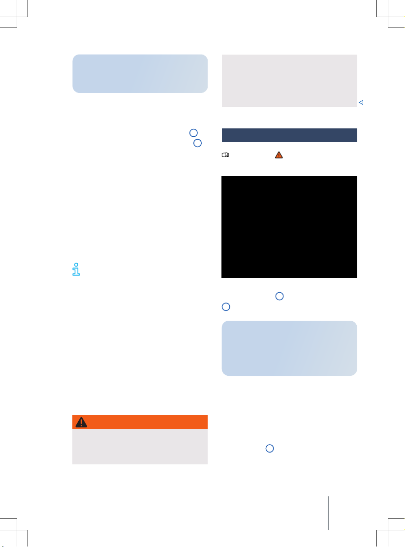
The power display shows the current
ormance capability of the electric
perf
drive and the current drive power.
Display concept
Using the bar divided in the middle, the power display continuously shows the availability
of brake energy recuperation → Fig. 13
(green) to the left and traction → Fig. 13 2
(blue) to the right. The availability is unrestricted when the respectiv
end marking. The bar is shown shortened in
each case if availability is restricted.
The current drive power is displayed dynamically by a lighter bar, either as brake energy
recuperation power (light green) to the left or
traction power (light blue) to the right.
The power limit of the electric drive is
reached when the current drive power and
currently available performance capability are
the same (bars are same length)
The power limit cannot be achieved at
all vehicle speeds.
Influencing factors
The following influencing factors apply in addition to the vehicle speed:
— The availability of traction and brake ener-
gy recuperation depends on the charge
level of the high-voltage battery. Brake
energy recuperation may be restricted by
a high charge level and traction by a low
charge level.
— Very low or very high temperatures of the
high-voltage battery can lead to an overall
reduction in the available drive power. This
applies to traction and brake energy recuperation
e bar reaches the
WARNING
If the performance capability of the electric
e is reduced or the charge level of the
driv
high-voltage battery has reached the reserve range, the driving characteristics can
11A012720AB
change, e.g. the acceleration performance
ehicle.
of the v
Always adapt your speed and driving
·
style to suit visibility, weather, road and
traffic conditions as well as the charge
level of the high-voltage battery.
1
Head-up display (HUD)
Please refer to at the start of the chap-
ter on page 18.
Fig. 14 In the driv
display close range
2 .
The head-up display (HUD) projects selected inf
from the assist systems or the Infotainment system into the driver's field of vision.
Display areas
Explanations of the areas shown in the headup display → Fig. 14:
— Head-up display close range
Information on speed, navigation and driver assist systems is displayed in the HUD
close range
— Augmented reality head-up display (AR
HUD)
er’s field of vision: head-up
1 and AR head-up display
ormation or warning messages
1 .
Instrument cluster 21
Page 24
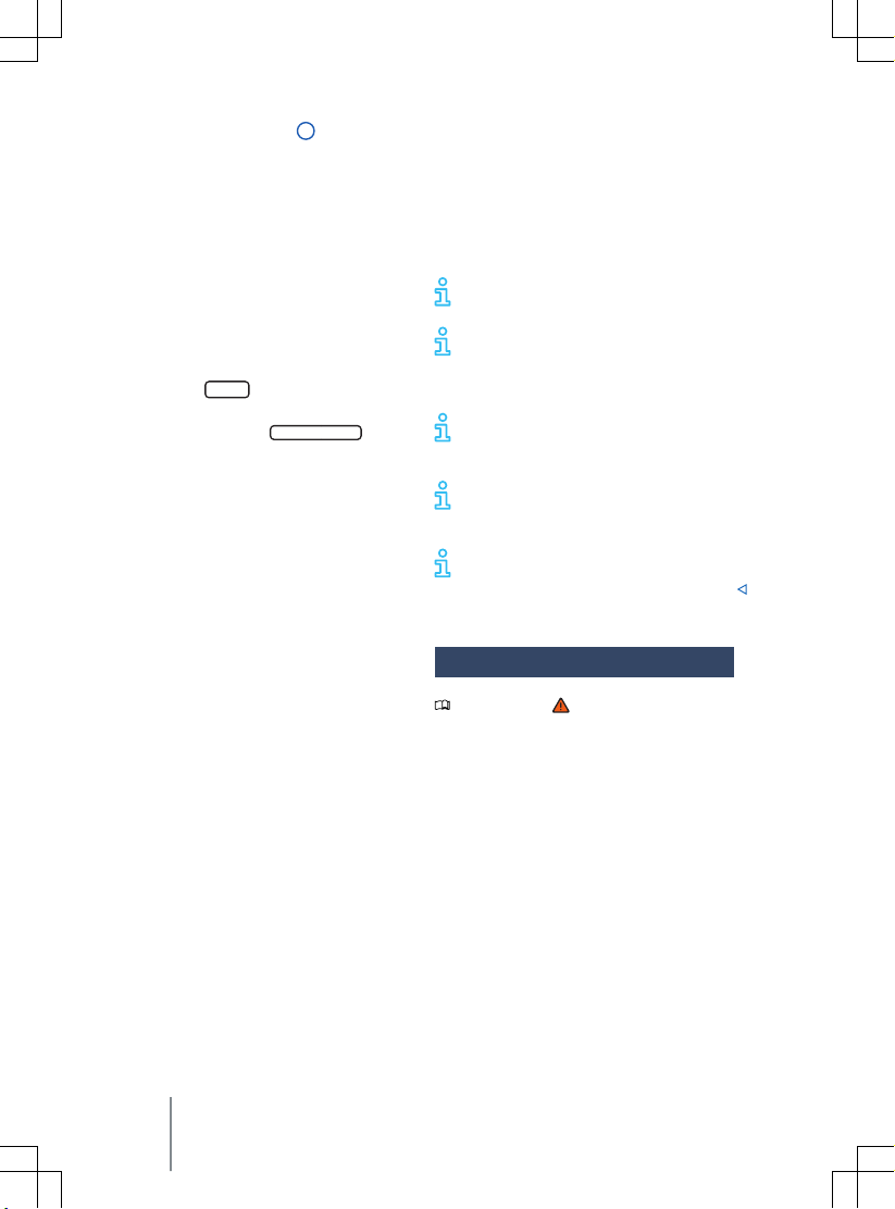
In augmented reality HUD 2 , information
can be projected directly into the driv
er's
field of vision depending on the situation.
The information may be for navigation
purposes, for example.
The amount and scope of the displayed information may differ depending on the vehicle
equipment.
Switching the head-up display on and off
The head-up display can be switched on and
off in the vehicle settings in the Infotainment
system.
Vehicle
1. Touch the
2.
In the
Vehicle
Interior
and touch the
function button.
selection, choose the view
Head-up
display
func-
tion button.
3.
Switch the head-up display on or off as
desired. The activated functions are
highlighted in colour.
Adjusting the height
In order to adjust the vertical position of the
image to your individual seating position, the
head-up display can be adjusted in the corresponding menu in the vehicle settings of the
Infotainment system.
1. Assume the correct sitting position.
2. Adjust the desired position and angle of
the head-up display using the function
buttons.
The rotation of the close range can also be
adjusted in the vehicle settings in the Infotainment system.
Settings in the Infotainment system
You can configure additional settings for the
head-up display in the vehicle settings in the
Infotainment system.
The following settings are available:
In the submenu
Head-up display settings
:
— Adjust the Head-up Display brightness. If
the surroundings become darker, the display brightness is automatically dimmed.
The basic brightness level is adjusted to-
gether with the instrument lighting
→ page 111.
Select the content of the head-up display,
—
e.g. to display the driver assist systems.
— Alternative colour scheme of the head-up
display for poor weather conditions, e.g.
snowfall.
Some content cannot be hidden,
e.g. warning messages.
The ideal position to read the head-
up display depends on the seat position and the height setting of the head-up
display.
Reflections can occur if the incident
sunlight strikes the display at an unfavourable angle.
Sunglasses with polarising filters can
negatively affect the readability of the
display.
Clean the head-up display with a soft
cloth and mild detergent only. Microfibre cloths can scratch the head-up display.
Displays
Please refer to at the start of the chap-
ter on page 18.
ossible notifications in the digital instru-
P
ment cluster
Depending on the vehicle equipment, various
kinds of information can be shown as overlays in the digital instrument cluster:
— Open doors, bonnet and boot lid.
— Warning and information messages
→ page 23.
— Navigation information.
— Outside temperature display.
— Service interval display.
— Range display.
— Speed warning function.
22 Driver information
Page 25
— Speed warning for winter tyres.
Road signs detected by the Dynamic Road
—
Sign Display system → page 25.
— Remaining charging time during charging
of the high-voltage battery.
Open doors, bonnet and boot lid
The digital instrument cluster indicates if any
doors, the bonnet or boot lid are open once
the vehicle has been unlocked and while the
vehicle is in motion. In some cases, an acoustic warning is also given.
Outside temperature display
If the outside temperature falls below approximately +4°C (+39°F), a snowflake symbol appears in the upper area of the digital
instrument cluster as an overlay
bol remains lit until the outside temperature
rises abo
ve +6°C (+43°F) .
In the following situation, the temperature
displayed may be higher than the actual outside temperature as a result of the heat radiated from the engine.
— When the vehicle is stationary.
— When travelling at very low speeds.
WARNING
Streets and bridges can be iced over at outside temperatures abo
The snowflake symbol indicates that
·
there is a risk of black ice.
There may also be black ice on the road
·
at outside temperatures above +4 °C
(+39 °F) when the snowflake symbol is
not displayed.
You should never rely solely on the out-
·
side temperature display!
Mileage displays
The odometer registers the total distance
velled by the car.
tra
Speed warning for winter tyres
A display in the digital instrument cluster indicates when you have exceeded the set
maximum speed.
11A012720AB
ve freezing point.
. This sym-
Speed warning settings can be made in the
ehicle settings in the Infotainment system
v
→ page 31.
Range display
Approximate calculation of the distance in
km that can still be travelled with the current
battery charge level under the current driving
conditions and with the same consumption.
This distance is calculated using factors that
include the current energy consumption.
Some notifications in the digital instrument cluster may be overridden by
sudden events, e.g. speed warning.
Depending on the vehicle equipment
level, some settings and displays may
also appear in the Infotainment system.
If several warnings are present, the
symbols will appear at the bottom in
the middle of the display for several seconds,
one after another. The symbols will continue
to appear until the faults are rectified.
If warnings about malfunctions are
displayed when the ignition is switched on, it may not be possible to adjust some
settings as described, or the information display may appear differently. If this is the
case, take the vehicle to a qualified workshop
to have the malfunctions rectified.
Warning and information
messages
Please refer to at the start of the chap-
ter on page 18.
The system runs a check on certain components and functions in the v
ignition is switched on or while the vehicle is
in motion. Malfunctions are indicated by red
and yellow warning symbols with information
messages on the instrument cluster display.
An acoustic warning is also given in certain
cases. The appearance of the text messages
ehicle when the
Instrument cluster 23
Page 26
and symbols can vary depending on the version of the instrument cluster.
Priority 1 warning
The red central warning lamp flashes or lights
up, in some cases together with acoustic
warnings or additional symbols. Do not
e on! Danger. Check the fault. Seek expert
driv
assistance if necessary.
Priority 2 warning
The yellow central warning lamp flashes or
lights up, in some cases together with acoustic warnings or additional symbols. Malfunctions and insufficient service fluids can dam-
ehicle and cause it to break down.
age the v
Check the fault as soon as possible. Seek expert assistance if necessary.
Reference to information in the owner's manual
You will find further information on the
warning in the owner's manual.
Inf
ormation message
Information about various procedures within
the vehicle.
If several warnings are present, the
symbols will appear for several seconds, one after another. The symbols will
continue to appear until the faults are rectified.
If warnings about malfunctions are
displayed when the ignition is switched on, it may not be possible to adjust some
settings as described, or the information display may appear differently. If this is the
case, take the vehicle to a qualified workshop
to have the malfunctions rectified.
Driver Alert System (break
recommendation)
Please refer to at the start of the chap-
ter on page 18.
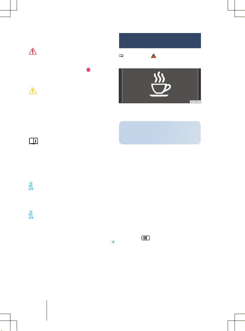
Fig. 15 On the instrument cluster display: Driv-
er Alert System symbol.
The Driver Alert System informs the driver if their driving shows signs of tiredness.
F
unction and operation
The Driver Alert System determines the driving behaviour at the beginning of a journey
and uses it to evaluate the tiredness of the
driver. This is compared to the behaviour of
the driver while actually driving. If the system
detects driver fatigue, an acoustic warning
signal will sound and a symbol will be displayed on the instrument cluster display together with a supplementary text message
→ Fig. 15. The message in the instrument
cluster display is displayed for about five seconds and may be repeated once. The last displayed message is saved by the system.
The message on instrument cluster display
can be deactivated as follows:
— Press the
steering wheel.
unction conditions
F
The driving behaviour can be evaluated only
when the speed is above 60 km/h (37 mph)
up to approximately 200 km/h (125 mph).
button on the multifunction
24
Driver information
Page 27
Switching on and off
You can switch the Driv
and off in the
tainment system. When the vehicle’s drive
system is activated, the Driver Alert System is
always activated too → page 31.
Function limitations
The Driver Alert System has system-related
limitations. The following conditions can limit
the function of the Driver Alert System, or
prevent it from working altogether:
— Speeds less than 60 km/h (37 mph).
— Speeds of more than 200 km/h (125 mph).
— Twisting roads.
— Road works.
— Poor roads.
— Adverse weather conditions.
— Sporty driving style.
— Driving with a trailer.
— The driver is distracted.
The Driver Alert System is reset in the following situations:
— The ignition is switched off.
— The driver seat belt is unfastened and the
driver door is open.
— The vehicle has been stationary for longer
than 15 minutes.
The Driver Alert System is automatically reset
in the event of an extended period of slow
driving (speed less than 60 km/h (37 mph)). If
the speed is increased again, the system
evaluates the driving behaviour once more.
er Alert System on
Assist systems
menu in the Info-
WARNING
The intelligent technology used in the Driver Alert System cannot o
of physics, and functions only within the
limits of the system. Do not let the extra
convenience afforded by the Driver Alert
System tempt you into taking any risks
when driving. During a long trip, plan regular and sufficient breaks.
11A012720AB
vercome the laws
er is responsible at all times for
The driv
·
their fitness to drive.
Never drive a vehicle when you are tired.
·
The system cannot always detect the
·
driver's level of alertness. Observe the
information in the section “Function limitations”.
In certain situations, the system may
·
wrongly interpret intentional driving
manoeuvres as a lack of alertness from
the driver.
No urgent warning will be given in the
·
event of the phenomenon known as
“microsleep”.
Observe the information in the instru-
·
ment cluster display and respond according to the commands.
The Driver Alert System has been dev
eloped for use only while driving on
motorways and good roads.
If there is a system fault, proceed to
a qualified workshop immediately to
have the system checked.
Dynamic Road Sign Display
Please refer to at the start of the chap-
ter on page 18.
Dynamic Road Sign Display uses a camera in the base of the interior mirror to
monitor standard road signs and inf
the driver of any detected speed limits,
overtaking restrictions and danger signs.
Within the system limits, the system also
displays an additional sign to indicate,
for example, temporary restrictions. In
some cases, the system can also display
the current speed limits on non-signposted routes.
The Dynamic Road Sign Display is always active when the ignition is switched on. Additional signs are displayed as a generic addi-
orms
Instrument cluster 25
Page 28

tional sign in the head-up display and in the
instrument cluster.
Displays
In addition to speed limits and o
vertaking restrictions, Dynamic Road Sign Display also
detects the road sign which indicates that all
restrictions have been lifted on motorways
and main roads in Germany. In all other countries in which the system is operated, the
current speed limit is displayed instead.
The road signs detected by the Dynamic Road
Sign Display system are displayed on the instrument cluster. Road signs may also be displayed in the Infotainment system, depending on the system installed in the vehicle.
With some equipment levels, a display is also
shown on the Head-up Display.
No road signs available.
The system is in the initialisation phase. OR: the camera has not
detected any regulatory or warning
signs.
Error: Dynamic Road Sign Display
System fault. Go to
a qualified workshop.
Speed warning currently not available.
Fault in the Dynamic Road Sign Display system
speed warning. Go to a qualified
workshop.
Dynamic Road Sign Display: Clean the windscreen!
The
windscreen is dirty in the area of the
camera or the camera view is impaired due to the weather conditions.
Clean the windscreen.
Dynamic Road Sign Display is currently restricted.
No data
transmission from the Infotainment
system. Check whether valid map data is loaded in the Infotainment system. OR: the vehicle is located in an
area that is not covered by the map
stored in the Infotainment system.
No data available.
Dynamic Road Sign Display is
not supported in the country in which
you are currently travelling.
Display of road signs
Fig. 16 In the instrument cluster display: e
ple of recognised speed limits with generic additional sign.
xam-
After validation and evaluation of the information from the camera, the Infotainment
system and the current vehicle data, the Dynamic Road Sign Display shows up to two
valid road signs and one generic additional
sign → Fig. 16:
1st position:
The road sign that currently applies to the driver is shown on the
left-hand side of the display, e.g. a
speed limit of
2nd position:
130 km/h (80 mph
).
A further road sign can be displayed in the second position, for example a danger sign.
Additional sign:
A detected additional sign,
e.g. with time restrictions, is displayed under the valid road sign. Due
to system limitations, a generic additional sign is displayed instead of the
additional sign actually detected. The
valid road sign is supplemented with
the generic additional sign in the
head-up display.
The display of danger signs is not available in
all countries and the system may not be able
to recognise all danger signs.
Speed warning
If the Dynamic Road Sign Display detects that
an applicable speed limit has been exceeded,
it issues a visual warning signal or warns visually and acoustically with a message on the
instrument cluster display.
The speed warning can be set or completely
deactivated in the
Assist systems
menu in the Infotainment system → page 31. The speed
warning can be set to a value of 0 km/h
26
Driver information
Page 29
(0 mph), 5 km/h (3 mph) or 10 km/h (5 mph)
ve the permitted speed.
abo
Trailer mode
In vehicles with a factory-fitted towing
bracket and a trailer with an electrical connection to the vehicle, the display of road
signs that may apply to the vehicle when
towing a trailer, e.g. applicable speed limits
and no-overtaking signs, can be activated or
deactivated in the vehicle settings in the Infotainment system → page 31.
In trailer mode, the speed warning function
display can be adjusted to the type of trailer
or to legal requirements. The settings can be
adjusted in increments of 10 km/h (5 mph)
within a range between 60 km/h (35 mph)
and 130 km/h (80 mph). If a higher speed is
set than is permitted for driving with a trailer
in the country in which you are currently
travelling, Dynamic Road Sign Display automatically issues a warning at the usual speed
limit, e.g. at 80 km/h (50 mph) in Germany.
No-entry warning
If the Dynamic Road Sign Display detects
a no-entry sign on a one-way road or motorway slip road, it will issue an acoustic warning signal and display a message on the instrument cluster display.
Function limitations
Dynamic Road Sign Display is subject to system-related limitations. The following conditions can restrict the function of Dynamic
Road Sign Display, or prevent it from working
altogether:
— Poor visibility, for example when it snows.
— Dazzling, for example by sunlight.
— High speeds.
— A covered or dirty camera.
— Road signs located outside of the camera's
field of view.
— Partially or fully hidden road signs, for ex-
ample by other vehicles.
— Non-standard road signs.
— Damaged or bent road signs.
11A012720AB
— Variable road signs on gantries (changea-
ble road sign display using LEDs or other
light sources).
— Out-of-date map material in the Infotain-
ment system.
— Vehicles with road sign stickers, e.g. speed
restrictions on trucks.
WARNING
The intelligent road sign recognition system technology cannot o
of physics, and functions only within the
limits of the system. Do not let the extra
convenience afforded by Dynamic Road
Sign Display tempt you into taking any risks
when driving. The system is not a substitute for the full concentration of the driver.
Always adapt your speed and driving
·
style to suit visibility, weather, road and
traffic conditions.
Poor visibility, darkness, snow, rain and
·
fog can cause traffic signs to be not displayed or be incorrectly displayed by the
system.
If the camera's field of view is dirty, cov-
·
ered or damaged, the function of the
Dynamic Road Sign Display system may
be impaired.
vercome the laws
WARNING
Driving recommendations and traffic symbols displayed by the Dynamic Road Sign
Display system may diff
traffic situation.
Not all road signs can be recognised by
·
the system and displayed correctly.
Road signs on the road and traffic regu-
·
lations have priority over the recommendations and displays provided by the Dynamic Road Sign Display system.
er from the current
Instrument cluster 27
Page 30
Eco assistance
Please refer to at the start of the chap-
ter on page 18.
Fig. 17 Eco Assistance display (illustration).
The Eco Assistance function supports you
during def
with notifications in the digital instrument
cluster that appear according to the situation
→ page 130.
If you are approaching a junction, for example, the
an event in the digital instrument cluster
→ page 18.
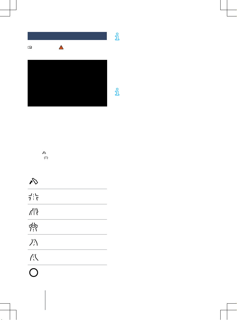
Overview of displayed symbols
ensive and energy-saving driving
symbol is displayed together with
Take your foot off the accelerator.
Junction ahead.
Motorway exit.
Roundabout ahead.
Left-hand bend.
Right-hand bend.
Speed limit with dynamic speed display.
The symbols displayed may differ
slightly depending on v
ment and model. Symbols may be altered or
upgraded by a system update.
As soon as you follow the instruction and
take your foot off the accelerator, the vehicle
will adapt brake energy recuperation and the
driving speed, depending on the selected
driving profile and distance to the event
→ page 135.
When the system is active, Eco Assis-
tance can also increase brake energy
recuperation without displaying a message.
This may be the case if you take your foot off
the accelerator when there is a vehicle in
front, for example. Here, brake energy recuperation is adapted to the vehicle in front
without any message being displayed.
The Eco Assistance function uses the route
data of the Infotainment system and the sensors of some assist systems. The most probable route is used if the route guidance function is not active.
You can override the intervention of the Eco
Assistance function at any time by pressing
the accelerator.
The Eco Assistance function can be activated
and deactivated in the assist system settings
in the Infotainment system → page 29.
The Eco Assistance function will be automatically deactivated temporarily in the following
cases:
— Position B.
—
Sport
driving profile.
— Driving with Adaptive Cruise Control (ACC)
(ACC) or cruise control system (CCS).
Eco Assistance will be activated again when
you leave these conditions if the function is
activated in the assist system settings as default.
The Eco assistance function is dependent on
the equipment level and is not available in all
countries.
ehicle equip-
28 Driver information
Page 31
WARNING
The system uses brake energy recuperation
to reduce the v
activate the vehicle brake.
Be ready to brake at all times if the de-
·
celeration is not sufficient.
ehicle speed and does not
WARNING
The system is not a substitute for the full
concentration of the driver.
Always adapt your speed and driving
·
style to the current visibility, weather
and road or traffic conditions.
Road signs on the road and traffic regu-
·
lations always have priority over driving
recommendations.
Time and date
Please refer to at the start of the chap-
ter on page 18.
Setting the time and date on the Inf
ment system
1. To access the
the
2.
Selection the menu option
3.
Select the time source:
— Automatic.
— Manual.
The time and date are displayed only on the
Infotainment system.
System settings
Settings
function button → page 31.
Button for driver assist systems
Please refer to at the start of the chap-
ter on page 18.
You can open the
fotainment system using the button for driv-
11A012720AB
Assist systems
otain-
menu, touch
and date
Time
menu in the In-
er assist systems. The button for the driver
assist systems is located on the control panel
under the Inf
In the
vidual driver assist systems on and off and also adjust individual settings → page 31.
1. Press the
2.
3. Open the corresponding driver assist
4. To return to the previous menu, touch
otainment system.
assist systems
Select 3D or optional list view.
system and make your desired setting.
The activated functions are highlighted
in colour.
the
ton.
menu, you can switch indi-
button.
sensor field or press the but-
Service menu
Please refer to at the start of the chap-
ter on page 18.
Opening the Service menu
Touch the
1.
Inf
2. In the
function button.
Select the
3.
.
Open the desired menu and make the
desired setting. The activated functions
are highlighted in colour.
4. Touch the
the pre
Resetting the trip recorder
1. In the
menu.
2. Touch the
the v
Displaying vehicle identification number
(VIN)
— In the
The vehicle identification number (VIN) is
displayed.
Vehicle
otainment system.
Vehicle
vious menu.
Status
alue.
Status
function button in the
menu, touch the
Status
view.
HOME
button
view, select the
0.0
function button to reset
view, select the
Status
to return to
Trip recorder
Service
menu.
Instrument cluster 29
Page 32
Service interval display
Please refer to at the start of the chap-
ter on page 18.
Service e
vents are displayed on the instru-
ment cluster and in the Infotainment system.
Service notification
When an inspection is due, a service announcement will appear on the instrument
cluster display when the ignition is switched
on.
The number of kilometres or amount of time
shown correspond to the maximum number
of kilometres or maximum time that can still
be driven before the next inspection.
Service event
For a scheduled inspection, an acoustic signal
will be given when the ignition is switched on
and the spanner symbol
for several seconds on the instrument cluster
display. One of the following displays will also appear:
Inspection now!
—
—
Inspection in xx km!
—
Inspection in xx days!
Accessing service schedules in the Infotainment system
— Touch the
— Touch the
Status
— Select the
the service information.
Resetting the service interval display
The service interval display can only be reset
as part of an inspection by a qualified workshop.
system has been activated or by pressing
the button on the multifunction steering wheel.
Vehicle
Status
view.
Service
The service message goes out after
a few seconds after the vehicle's drive
will be displayed
function button.
function button and the
menu option to display
Infotainment system controls and displays
Introduction to the topic
The Infotainment system combines key
ehicle systems in a central operating
v
unit, e.g. menu settings, radio or navigation system.
General information on operation
The following section contains relevant information on the settings that can be adjusted
Vehicle
in the
Systems settings and v
display
After touching the
inf
ormation can be displayed or settings
made by touching the corresponding function
buttons. The current vehicle status can be
displayed by touching the
button, f
— Vehicle settings → page 31.
— Vehicle status.
— Driving data.
Accidents and injuries can occur if the driver is distracted. Operating the Inf
system can distract you from the road.
·
has been totally discharged or replaced, system settings such as time, date, personal
convenience settings and programming and
also user accounts may have been changed or
deleted. Check and correct the settings as
necessary once the 12-volt vehicle battery
has been sufficiently charged.
menu.
ehicle information
Vehicle
function button,
Status
or example:
function
WARNING
otainment
Always drive carefully and responsibly.
After activating the vehicle’s drive system after the 12-
volt vehicle battery
30 Driver information
Page 33
Vehicle settings menu
Please refer to at the start of the chap-
ter on page 30.
You can switch individual functions and
systems on and off and adjust the settings in the vehicle settings of the Infotainment system.
Opening the
1. Switch on the ignition.
2. Switch on Infotainment system if neces-
3. Touch the
4.
5. Open the desired menu and make the
Vehicle settings
sary.
Touch the corresponding function buttons from
tional submenus in the
adjust settings in the menu options.
desired setting.
The activated functions are highlighted
in colour.
Vehicle
function button.
Interior
or
menu
Exterior
Exit menu
Please refer to at the start of the chap-
ter on page 30.
In the Exit menu, you can adjust settings
f
or some functions before you leave the
vehicle. When you switch off the ignition, the Exit menu will be displayed in
the Infotainment system.
The displayed options depend on the vehicle
equipment and may be available only under
certain conditions. The adjustable functions
may include the following, for example:
— Charging the high-voltage battery.
11A012720AB
to open addi-
Vehicle
menu or to
— Auxiliary heater or stationary air condition-
ing.
—
Interior monitoring.
Hiding
The Exit menu is automatically hidden when
you leave the vehicle. The Exit menu is also
hidden after a certain time depending on the
vehicle equipment.
— Touch
Setting
You can change the order of the displayed
options.
1.
2.
3. Touch
to hide the Exit menu manually.
.
Touch
Rearrange the options into your prefer-
red order.
again.
ID. Light
ID. Light is an intelligent light concept
that displays additional information on
the vehicle status. When the vehicle’s
drive system is activated and while driving, supporting information on the current driving situation is provided via
ID. Light.
Displayed information
— Locking and unlocking.
— Welcome and goodbye animation.
— Charging operations.
— Voice control.
— Phone call.
— Navigation.
— Reduced power.
— Front Assist braking request
The displayed information may be
changed and extended by a system up-
date.
31
Page 34

Brightness
Touch the
1.
the control centre.
Adjust the brightness by means of the
2.
touch slider.
OR:
1. Touch the
Inf
2. Select display content for the
Then touch the
Adjust the brightness by means of the
3.
touch slider.
4. Touch the
the pre
Settings in the Infotainment system
1. Touch the
2.
Select display content for the
Then touch the
3.
Set the functions for ID. Light as desired.
The activated functions are highlighted
in colour.
Certain ID. Light functions can be optionally
activated or deactivated in the vehicle settings in the Infotainment system.
— Touch the
pre
Brightness
Vehicle
otainment system.
HOME
button
vious menu.
Vehicle
HOME
vious menu.
button
function button in
function button on the
Interior
to return to
Interior
.
.
ID. Light
function button.
function button.
ID. Light
function button.
to return to the
Safety
General notes
Preparing f
Observe the following information both before and during every journey to ensure your
own safety, and the safety of all passengers
and other road users → page 34, General
notes:
✓ Check that all lights and turn signals are
✓ Check the tyre pressure and charge level
✓ Check the washer fluid level
✓ Make sure that you have a good, clear
✓ Air intake to the electric drive must not
✓ Secure all objects and luggage in the
✓ Ensure that you are able to operate the
✓ Secure any children travelling in the ve-
✓ Adjust the front seats, head restraints
✓ Wear shoes that provide good grip for
✓ The floor mat in the footwell on the driv-
✓ Assume a correct sitting position before
or a journey and driving safety
working properly.
→ page 332, → page 284.
→ page 314.
view through all of the windows
→ page 358.
be obstructed, and the electric drive
must not be covered by blankets or insulating materials → page 309.
stowage compartments or the luggage
compartment → page 254.
pedals freely at all times.
hicle in a restraint system suitable for
their weight and size → page 57.
and mirrors properly in accordance with
the size of the occupants → page 34,
→ page 115.
your feet when using the pedals.
er side must leave the pedal area free
and must be securely fastened.
setting off and maintain this position
while driving. This also applies to all passengers → page 34.
32 Safety
Page 35

asten your seat belt correctly before
✓ F
setting off and keep it properly fastened
throughout the journey. This also applies
to all passengers → page 36.
✓ Each vehicle occupant must sit in a seat
of their own and must have their own
seat belt.
✓ Never drive if your driving ability is im-
paired, e.g. by medication, alcohol or
drugs.
✓ Do not allow yourself to be distracted
from the traffic, e.g. by passengers, telephone calls, opening menus and making
adjustments to settings.
✓ Always adapt your speed and driving
style to suit visibility, weather, road and
traffic conditions.
✓ Observe traffic regulations and speed
limits.
✓ Take regular breaks when travelling long
distances – at least every two hours.
✓ Secure animals in the vehicle using
a system that is suitable for their weight
and size.
Driving abroad
In some countries, special safety standards
and regulations apply that the v
not comply with. Volkswagen recommends
that you visit your Volkswagen dealership before travelling abroad to find out about any
legal requirements and the following issues
at your destination:
✓ Does the vehicle need any technical
modifications for driving abroad,
e.g. masking or switching the headlights
over?
✓ Are the necessary tools, diagnostic
equipment and spare parts available for
service and repair work?
✓ Are there any Volkswagen dealerships in
the destination country?
✓ Are the correct service fluids that com-
ply with Volkswagen specifications available in the destination country
11A012720AB
→ page 313?
ehicle may
✓ Does the na
vigation function in the factory-fitted Infotainment system work
with the navigation data available in the
destination country?
✓ Are special tyres necessary for travelling
in the destination country?
✓ Is a fire extinguisher a requirement in
your destination country?
✓ Which requirements must be observed
regarding high-visibility waistcoats?
✓ Are special charging cables necessary for
charging at mains sockets in the destination country?
Checks when charging
Never carry out work on the high-voltage
system yourself
. Do not perform any work in
the bonnet space unless you know exactly
how to carry out the tasks, are aware of the
general safety procedures and have the correct equipment, service fluids and suitable
tools to hand → page 309. In any other case,
all work must be carried out by a qualified
workshop. Make sure that the following are
checked regularly:
✓ Washer fluid level → page 314.
✓ Coolant level → page 315.
✓ Brake fluid level → page 318.
✓ Tyre pressure → page 332.
✓ Vehicle lighting → page 103 necessary
for traffic safety:
— Turn signals.
— Side lights, dipped beam headlights
and main beam headlights.
— Tail light clusters.
— Brake lights.
— Rear fog light.
— Number plate light.
Information on changing bulbs → page 295.
General notes 33
Page 36
DANGER
Please observe important safety information about the front passenger front airbag
→ page 59.
DANGER
The voltage of the high-voltage system is
dangerous and can cause burns or other injuries and even lead to a fatal electric
shock.
Please observe the important safety in-
·
formation about the high-voltage system and the high-voltage battery
→ page 273.
WARNING
Driving under the influence of alcohol,
drugs, medication or narcotics can cause
serious accidents and fatal injuries.
Alcohol, drugs, medication and narcotics
·
verely impair perception, reaction
can se
times and driving safety. This could
cause you to lose control of the vehicle.
WARNING
Always observe current traffic regulations
and speed limits, and think ahead when
driving. Correct interpretation of a driving
situation can make the diff
reaching your destination safely and having
an accident with serious injuries.
erence between
NOTICE
Volkswagen is not responsible for any vehicle
damage caused by inadequate servicing work
or lack of Genuine P
Please observe the notes and information f
→ page 373.
Servicing the vehicle regularly is not
only about vehicle maintenance – it also ensures that your vehicle remains roadworthy and in perfect working order. You
should therefore have your vehicle serviced
according to the Volkswagen guidelines.
arts.
or vehicles with N1 approval
Some work may have to be carried out before
the due date of the ne
is subjected to heavy-duty operating conditions. Heavy-duty conditions are, for example, regular stop and go driving or driving in
areas with high levels of dust. Further information can be obtained from your Volkswagen dealership or qualified workshop.
xt service if the vehicle
Sitting position
Introduction to the topic
Number of seats
ehicle has a total of five seats: two at
The v
the front and three at the rear.
Each seat is equipped with a seat belt.
WARNING
Assuming an incorrect sitting position in
ehicle can increase the risk of severe
the v
or fatal injuries during a sudden driving or
braking manoeuvre, in the event of a collision or accident, or if the airbags are triggered.
All vehicle occupants must assume
·
a correct sitting position before setting
off and maintain this position throughout the trip. This also applies to the fastening of seat belts.
The number of vehicle occupants must
·
never exceed the number of seats with
seat belts in the vehicle.
Always secure children in the vehicle in
·
an authorised child restraint system
which is suitable for their height and
weight → page 57 and → page 47.
Always keep your feet in the footwell
·
while the vehicle is in motion. Never
place your feet on the seat or dash panel, for example, and never ride with your
feet out of the window. If you sit like
this, the airbag and seat belt cannot provide optimal protection and could ac-
34
Safety
Page 37
tually increase the risk of injury during
an accident.
— Never travel on a seat without wearing the
seat belt.
Never travel in the luggage compartment.
—
The dangers of assuming an
incorrect sitting position
Please refer to at the start of the chap-
ter on page 34.
If the seat belts are not worn or are worn incorrectly, the risk of se
increases. Seat belts can only provide optimal
protection if the seat belt routing is correct.
Assuming an incorrect sitting position considerably impairs the level of protection provided by a seat belt. This could lead to severe
or even fatal injuries. The risk of severe or fatal injuries is especially increased when a deploying airbag strikes a vehicle occupant who
has assumed an incorrect sitting position.
The driver is responsible for all occupants
transported in the vehicle, especially children.
The following list contains examples of sitting positions that can be dangerous for all
vehicle occupants.
Whenever the vehicle is in motion:
— Never stand in the vehicle.
— Never stand on the seats.
— Never kneel on the seats.
— Never tilt the backrest too far to the rear.
— Never lean against the dash panel.
— Never lie on the seats in the passenger
compartment and on the rear bench seat.
— Never sit on the front edge of a seat.
— Never sit sideways.
— Never lean out of a window.
— Never put your feet out of a window.
— Never put your feet on the dash panel.
— Never place your feet on the seat cushion
or seat backrest.
— Never travel in a footwell.
— Never sit on the armrests.
11A012720AB
vere or fatal injuries
WARNING
Every incorrect sitting position in the vehicle increases the risk of se
ries in the event of an accident or sudden
driving or braking manoeuvre.
All vehicle occupants must maintain
·
a correct sitting position and wear their
seat belt properly while the vehicle is in
motion.
Sitting in an incorrect position, not fas-
·
tening the seat belt, or not leaving adequate space between the occupants and
the airbags could result in critical or fatal
injuries, especially if the airbags deploy
and strike an occupant who has assumed
an incorrect sitting position.
vere or fatal inju-
Correct sitting position
Please refer to at the start of the chap-
ter on page 34.
Fig. 18 Illustration: correct distance between
er and the steering wheel, correct seat
the driv
belt routing and correct head restraint adjustment.
The following describes the correct sitting
positions for the driver and passengers.
If any vehicle occupants cannot assume
a correct sitting position due to their physical
build, they should contact a qualified work-
Sitting position
35
Page 38
shop to find out about possible special modifications. The seat belts and airbags can only
vide a maximum level of protection if
pro
a correct sitting position is assumed. Volkswagen recommends using a Volkswagen
dealership for this purpose.
Volkswagen recommends the following seating position for your own safety and to reduce the level of injury in the event of a sudden braking manoeuvre or an accident:
The following applies to all vehicle occupants:
— Adjust the head restraint so that its upper
edge is at the same height as the top of
the head, but not lower than eye level. Position the back of your head as close to the
head restraint as possible at all times
→ Fig. 18.
— For small people, push the head restraint
all the way down, even if the head is then
located underneath the top edge of the
head restraint.
— For tall people, push the head restraint up
as far as it will go.
— Keep both feet in the footwell while the
vehicle is in motion.
— Adjust and fasten seat belts properly
→ page 36.
Additional points for the driver:
— Move the backrest into an upright position
so that your back rests fully against it.
— Adjust the seat so that the distance be-
tween the steering wheel and your breastbone is at least 25 cm (around 10 inches)
→ Fig. 18
steering wheel can be held at the sides
with both hands and your arms slightly
bent.
The steering wheel must always point to-
—
wards the breastbone and not towards the
face.
— Adjust the driver seat by moving it for-
wards or backwards so that you are able to
press the pedals to the floor with your
knees still slightly bent and so that the
A and the circumference of the
distance from the dash panel to your
knees is at least 10 cm (
→ Fig. 18
Adjust the height so that you can reach
—
the highest point of the steering wheel.
— Always leave both feet in the footwell to
help ensure you maintain control of the
vehicle at all times.
— Adjust and fasten seat belts properly
→ page 36.
Additional points for the front passenger:
— Move the backrest into an upright position
so that your back rests fully against it.
— Push the front passenger seat as far back
as possible so that the airbag can provide
maximum protection if it is deployed.
B .
around 4 inches)
Seat belts
Introduction to the topic
Check the condition of all seat belts regularly.
If the belt webbing, belt connections, belt retractor or seat belt buckle become damaged,
the seat belt in question should be replaced
immediately by a qualified workshop → .
The qualified workshop must use correct
spare parts that are compatible with the v
hicle, equipment level and model year. Volkswagen recommends using a Volkswagen
dealership for this purpose.
WARNING
Incorrectly fastened or unfastened seat
belts increase the risk of se
juries. Seat belts will only offer the optimum level of protection when they are fastened and used properly.
Seat belts are the most effective means
·
of reducing the risk of serious and fatal
injuries in the event of an accident. Seat
belts must always be fastened properly
when the vehicle is in motion to protect
the driver and all vehicle occupants.
vere or fatal in-
e-
36
Safety
Page 39
ore every trip, each vehicle occupant
Bef
·
must adopt the correct sitting position,
correctly fasten the seat belt belonging
to their seat and keep it fastened properly throughout the trip. This applies to
all vehicle occupants and also in urban
traffic.
While the vehicle is in motion, secure all
·
children travelling in the vehicle in a restraint system suitable for their weight
and height. They must also wear correctly fastened seat belts → page 57.
Only start driving when all passengers
·
have correctly fastened their seat belts.
Always insert the latch plate only into
·
the buckle of the associated seat, and
ensure that it engages properly. Using
a buckle that does not belong to the
seat that you are occupying reduces the
level of protection and can lead to severe injuries.
Avoid allowing foreign bodies or liquids
·
to enter the slot for the seat belt buckle.
This could prevent the belt buckle and
seat belt from working properly.
Never unfasten the seat belt while the
·
vehicle is in motion.
Never allow more than one person to
·
share the same seat belt.
Never travel when children or babies are
·
being carried on somebody's lap and
fastened with the same belt.
Never travel wearing loose, bulky cloth-
·
ing (such as an overcoat over a jacket).
This could prevent the seat belts from
fitting and functioning properly.
WARNING
Damaged seat belts are very dangerous and
can cause se
·
·
11A012720AB
vere or fatal injuries.
Never damage the belt by trapping it in
the door or in the seat mechanism.
If the belt webbing or any other part of
the seat belt becomes damaged, the
seat belt may tear during an accident or
sudden braking manoeuvre.
ve damaged seat belts immediately
Ha
·
replaced by new seat belts that have
been approved by Volkswagen for the
vehicle. Seat belts subjected to stress
and stretched during an accident must
be replaced by a qualified workshop. Renewal may be necessary even if there is
no apparent damage. The belt anchorages should also be checked.
Never try to repair, modify or remove
·
the seat belts yourself. All repairs to the
seat belts, belt retractors and buckles
must be carried out by a qualified workshop.
Warning lamp
Please refer to at the start of the chap-
ter on page 36.
Fig. 19 On the instrument cluster display:
warning lamp.
Buckle-up request f
If the driver or front passenger seat is occupied by an adult, an acoustic warning will be
emitted for 126 seconds if the seat belts are
not fastened at the start of a journey and the
vehicle reaches a speed of more than around
25 km/h (around 15 mph) or if the seat belts
are unfastened while the vehicle is in motion.
The red warning lamp
es on the instrument cluster display.
The red warning lamp will not go out until
all occupants ha
when the ignition is switched on.
or the front seats
→ Fig. 19 also flash-
ve fastened their seat belts
Seat belts
37
Page 40

Belt status display for the rear seats (depending on country and equipment)
Fig. 20 On the instrument cluster display: seat
belt status f
After the ignition has been switched on, the
belt status display → Fig. 20 on the instrument cluster display shows the driver whether the adult rear seat passengers have fastened their seat belts.
The following symbols light up in different
colours depending on whether seats are occupied and on the belt status:
Buckle-up request f
pending on country and equipment)
If a seat belt for one of the rear seats is unfastened while the vehicle is in motion, the
symbol will light up red continuously for this
seat. The red warning lamp also flashes on
the instrument cluster display. If the v
is travelling faster than around 25 km/h
(around 15 mph) an acoustic signal will also
be given for 126 seconds.
or the rear seats.
The red symbol indicates that the
passenger on this seat has not fastened their seat belt.
The green symbol indicates that the
passenger on this seat has fastened
their seat belt.
The white symbol indicates that this
seat is not occupied.
or the rear seats (de-
ehicle
WARNING
The buckle-up request is designed to detect adult persons. If a seat is occupied by
lighter persons, in particular children, the
detection will not be reliable. The buckleup request also does not respond or only in
a limited way if child seats and seat supports are used.
Always ensure that all v
·
especially children, have fastened their
seat belts properly.
ehicle occupants,
Frontal collisions and the
laws of physics
Please refer to at the start of the chap-
ter on page 36.
Fig. 21 Unbelted occupants in a v
ing for a brick wall.
ehicle head-
WARNING
Incorrectly fastened or unfastened seat
belts increase the risk of severe or fatal injuries. Seat belts will only offer the optimum level of protection when they are fastened and used properly.
38
Safety
Fig. 22 Unbelted occupants in a v
ing for a brick wall.
The physical principles involved in a frontal
collision are relatively simple. As soon as the
ehicle head-
Page 41

vehicle is in motion, both the moving vehicle
and its occupants gain “kinetic energy”
→ Fig. 21.
The higher the v
the weight of the vehicle, the greater the
amount of energy that will be released in the
event of an accident.
However, the most significant factor is the
speed of the vehicle. For example, if the
speed doubles from around 25 km/h to
around 50 km/h (around 15 mph to around
31 mph), the kinetic energy increases by
a factor of four.
The amount of kinetic energy depends on the
speed of the vehicle and the weight of the
vehicle and passengers. The higher the speed
and the heavier the weight, the greater the
amount of energy that will be released in the
event of an accident.
Passengers not wearing seat belts are not
“connected” to the vehicle. In the event of
a frontal collision, they will continue to move
forwards at the same speed at which the vehicle was travelling before impact, until
something stops them. Because the passengers in our example are not restrained by seat
belts, the entire amount of kinetic energy will
only be released at the point of impact
against the wall → Fig. 22.
In the event of an accident at speeds between around 30 km/h (around 19 mph) and
around 50 km/h (around 31 mph), forces act
on the body which can easily exceed one
tonne (1,000 kg or around 2,200 lbs). These
forces are even greater at higher speeds.
This example applies not only to frontal collisions, but to all accidents and collisions.
11A012720AB
ehicle speed and the heavier
What happens to vehicle occupants who ha
ve not fas-
tened their seat belts
Please refer to at the start of the chap-
ter on page 36.
Fig. 23 An unbelted driv
Fig. 24 The unbelted rear passenger is thrown
f
orwards, hitting the belted driver.
Many people believe that they can brace their
weight with their hands in a minor collision.
This is not true.
Even at low speeds, the forces acting on the
body in a collision are so great that it is not
possible to brace oneself with arms and
hands. In a frontal collision, vehicle occupants who have not fastened their seat belts
will be thrown forward and will make unchecked contact with parts of the vehicle in-
er is thrown forwards.
Seat belts
39
Page 42

terior, e.g. the steering wheel, dash panel, or
windscreen → Fig. 23.
The airbag system is not a substitute f
seat belts. When triggered, the airbags only
provide additional protection. Airbags are not
triggered in all kinds of accidents. Even if the
vehicle is equipped with an airbag system, all
vehicle occupants, including the driver, must
fasten their seat belt and wear it correctly
while the vehicle is in motion. This reduces
the risk of severe or fatal injuries in the event
of an accident – regardless of whether an airbag is fitted for the seat.
Each airbag can only be triggered once. To
achieve best possible protection, seat belts
must always be worn properly. This also ensures that protection is provided in accidents
in which the airbag is not triggered. Any vehicle occupants not wearing a seat belt can be
thrown out of the vehicle and sustain more
severe or even fatal injuries as a result.
It is also important for the rear seat occupants to wear seat belts properly, as they
could otherwise be thrown forwards violently
in an accident. Rear passengers who are not
wearing seat belts endanger not only themselves and the driver, but also other people in
the vehicle → Fig. 24.
or the
Seat belt protection
Please refer to at the start of the chap-
ter on page 36.
Fig. 25 Driv
tioned seat belt during a sudden braking manoeuvre.
Correctly fastened seat belts can make a major difference. When fastened properly, seat
belts hold the vehicle occupants in the correct sitting positions and considerably reduce
the kinetic energy in the event of an accident.
Seat belts also help to prevent uncontrolled
movements that could lead to severe injuries.
In addition, wearing seat belts properly reduces the risk of being thrown from the vehicle → Fig. 25.
Passengers wearing seat belts correctly benefit greatly from the ability of the belts to reduce the kinetic energy. The front crumple
zones and other passive safety features (such
as the airbag system) are also designed to reduce kinetic energy. The amount of energy
generated will thus decrease, thereby reducing the risk of injury.
The examples describe frontal collisions. Of
course, properly worn seat belts substantially
reduce the risk of injury in all other types of
accidents. This is why seat belts must be fastened before every trip – even if you are only
planning to drive a very short distance. Ensure that all passengers also wear their seat
belts properly.
er restrained by a properly posi-
40
Safety
Page 43
Accident statistics have shown properly worn
seat belts to be an eff
stantially reducing the risk of injury and improving the chances of survival in a serious
accident. Furthermore, properly worn seat
belts improve the protection provided by airbags in the event of an accident. This is why
wearing a seat belt is a legal requirement in
most countries.
Although the vehicle is equipped with airbags, the seat belts must be fastened and
worn. For example, the front airbags will be
triggered only in certain types of frontal collision. The front airbags will not be triggered
during minor frontal collisions, minor side
collisions, rear collisions, rolls or accidents in
which the airbag trigger threshold in the control unit is not exceeded. The same applies to
the other airbags in the vehicle.
Therefore, always wear your seat belt and ensure that your passengers have fastened their
seat belts properly before you drive off.
ective means of sub-
Using seat belts
Please refer to at the start of the chap-
ter on page 36.
Checklist
Using the seat belts → :
✓ Check the condition of all seat belts reg-
ularly.
✓ Keep the seat belts clean.
void allowing any foreign bodies or flu-
✓ A
ids to get on to the seat belt or latch
plate or into the slot for the seat belt
buckle.
✓ Do not trap or damage the seat belt and
latch plate, for example when closing
the door.
✓ Never remove, modify or repair the seat
belt or any part of the belt fixture system.
11A012720AB
✓ Always fasten the seat belt correctly be-
ore every journey and keep it fastened
f
while the vehicle is in motion.
Twisted seat belt
If it is difficult to remo
the belt guide, the seat belt may have become twisted if it was returned too quickly
into the side trim:
— Take hold of the latch plate then slowly
and carefully pull out the seat belt.
— Untwist the seat belt and guide it back
slowly by hand.
Fasten the seat belt even if you are unable to
undo the twist. However, the twist should
not be in part of the seat belt that comes into
direct contact with the body. The twist
should be corrected immediately by a qualified workshop.
ve the seat belt from
WARNING
Using seat belts incorrectly increases the
vere or fatal injuries.
risk of se
Regularly check to see if the seat belt
·
and its related parts are in perfect condition.
Always keep the seat belt clean.
·
Do not allow the belt webbing to be-
·
come jammed, damaged or to rub on
any sharp edges.
Always keep the latch plate and slot in
·
the buckle free from foreign bodies and
liquids.
Fastening and unfastening
seat belts
Please refer to at the start of the chap-
ter on page 36.
If worn properly, seat belts hold the v
occupants in the correct sitting position during an accident or braking manoeuvre, providing maximum protection →
ehicle
.
Seat belts 41
Page 44
In vehicles with a proactive occupant protection system, the driv
seat belts are automatically tensioned in certain situations → page 45.
Fastening the seat belts
Fig. 26 Inserting the seat belt latch plate into
the buckle.
asten seat belts before every trip.
F
— Adjust the front seat and head restraint
correctly → page 34.
— Engage the seat backrest in an upright po-
sition →
—
Take hold of the belt and pull it evenly
across your chest and pelvis. Do not twist
the belt in the process →
—
Insert the latch plate securely into the
buckle belonging to the occupied seat
→ Fig. 26.
— Pull on the seat belt to ensure that the
latch plate is securely locked in the buckle.
Unfastening the seat belts
er and front passenger
.
.
Unfasten seat belts only when the vehicle is
stationary →
Press the red button in the buckle
—
→ Fig. 27. The latch plate is released and
springs out.
— Guide the belt back by hand so that it rolls
up easily, without twisting the seat belt
and without damaging the trim.
.
WARNING
Incorrect seat belt routing can cause severe
or fatal injuries in the e
The seat belts only offer best protection
·
when the backrests are in an upright position and the seat belts have been fastened properly according to the occupant's height.
Unfastening seat belts while the vehicle
·
is in motion can lead to severe or fatal
injuries in the event of an accident or
sudden braking manoeuvre.
vent of an accident.
Seat belt routing
Please refer to at the start of the chap-
ter on page 36.
Fig. 27 Remo
buckle.
42 Safety
Fig. 28 Correct seat belt routing and head restraint adjustment.
ving the latch plate from the
Page 45
Fig. 29 Correct seat belt routing during pregnancy.
Seat belts only pro
protection during an accident when they are
routed correctly. Correct seat belt routing reduces the risk of severe or fatal injuries. Correct seat belt routing also holds the vehicle
occupants in position so that an inflating airbag can offer the maximum level of protection. Therefore you must always fasten your
seat belt and ensure that the seat belt routing is correct → Fig. 28.
Assuming an incorrect sitting position can
cause severe or fatal injuries → page 34.
Correct seat belt routing
— The shoulder belt must always lie on the
centre of the shoulder, never across the
neck, over or under the arm or behind the
back.
— The lap belt must always lie across the
pelvis, never across the stomach.
— The seat belt must always lie flat and
snugly on the body. Tighten the belt if
necessary.
For pregnant women, the seat belt must be
positioned evenly over the chest and as low
as possible over the pelvis. It must lie flat so
that no pressure is exerted on the lower body
– this applies for the entire course of the
pregnancy → Fig. 29.
Correct seat belt routing according to height
The following equipment can be used to adjust the seat belt routing:
11A012720AB
vide an optimum level of
— Seat belt height adjuster for the front
seats → page 44.
—
Height-adjustable front seats → page 34.
WARNING
Incorrect seat belt routing can cause severe
injuries in the e
a sudden braking or driving manoeuvre.
The seat belts only offer best protection
·
when the backrests are in an upright position and the seat belts have been fastened properly.
The seat belt itself or a loose seat belt
·
can cause serious injuries if the seat belt
shifts from harder body parts in the direction of softer body parts (e.g. stomach).
The shoulder part of the seat belt must
·
lie on the centre of the shoulder and
never under the arm or across the neck.
The seat belt must lie flat and snugly on
·
the chest.
The lap part of the seat belt must lie
·
across the pelvis and never across the
stomach. The seat belt must lie flat and
snugly on the pelvis. Tighten the belt if
necessary.
For pregnant women, the lap part of the
·
seat belt must be as low as possible over
the pelvis and lie flat around the “bulge”
of the belly.
Do not twist the belt webbing while the
·
seat belt is being worn.
Never hold the seat belt away from the
·
body by hand.
The belt webbing should not lie over
·
hard or fragile objects, such as glasses,
pens or keys.
Never use seat belt clips, retaining rings
·
or similar items to alter the seat belt
routing.
erly, contact a qualified workshop to find out
about any special modifications so that the
vent of an accident or
If a person's physical build prevents
them from routing the seat belt prop-
Seat belts 43
Page 46

seat belts and airbags can provide the opti-
vel of protection. Volkswagen recom-
mum le
mends using a Volkswagen dealership for this
purpose.
Seat belt height adjuster
Please refer to at the start of the chap-
ter on page 36.
Fig. 30 Ne
juster.
The seat belt height adjusters for the front
seats can be used to adjust the position of
the seat belt on the shoulder so that it can be
fastened properly:
— Push the shoulder belt guide together in
— Push the shoulder belt guide up or down
— Let go of the shoulder belt guide.
— Pull sharply on the seat belt to check
xt to the front seats: belt height ad-
the direction of the arrows and hold
→ Fig. 30.
so that the seat belt is routed over the
middle of the shoulder → page 42.
whether the shoulder belt guide is engaged securely.
WARNING
Never adjust the seat belt height when the
v
ehicle is in motion.
Belt retractor, belt tensioner,
belt tension limiter
Please refer to at the start of the chap-
ter on page 36.
The saf
ety belts in the vehicle are part of the
vehicle safety concept → page 47. The vehicle safety concept has the following important functions:
Belt retractor
The seat belts on the driver seat and front
passenger seat, as well as those on the outer
rear seats (and on the middle rear seat, depending on the level of vehicle equipment),
are fitted with an automatic belt retractor at
the shoulder part of the seat belt. Full freedom of movement is ensured when the
shoulder belt is pulled slowly or when the vehicle is travelling at normal speeds. However,
if the belt is pulled out quickly or during sudden braking, during travel in mountains or
bends and during acceleration, the belt retractor blocks the seat belt.
Fastened seat belts on the front seats may be
tensioned automatically by the proactive occupant protection system in critical situations, for example during an emergency stop
or in the event of oversteering or understeering. Both seat belts are slackened again if the
accident does not happen, or when the critical situation has passed. The proactive occupant protection system is ready to be triggered again → page 45.
Belt tensioner
The seat belts for the front seat vehicle occupants, and, depending on the vehicle equipment, those on the outer rear seats, are
equipped with belt tensioners.
The belt tensioners are activated by sensors
during severe frontal, side and rear collisions
and also possibly vehicle rollovers. They
tighten the seat belts against the direction in
which they are pulled. Any slack in the seat
belt is tightened. This can reduce the forward
movement of the vehicle occupants and their
movement in the direction of the impact. The
Safety
44
Page 47
belt tensioner works together with the airbag
system. If the v
sioner will not be activated if the curtain airbags are not triggered.
A fine dust may be produced when the airbags are triggered. This is quite normal and
does not mean that there is a fire in the vehicle.
Reversible belt tensioning (proactive occupant protection system)
Reversible belt tensioning may trigger in certain driving situations → page 45. Examples
include:
— Strong braking.
— Oversteer or understeer.
— Minor collisions.
tain driving situations. In this case, the seat
belts must be manually unfastened when the
vehicle is stationary and then fastened correctly again in order to release the belt tensioning.
Belt tension limiter
The belt tension limiter reduces the pressure
exerted by the seat belt on the body during
an accident.
nents of the system are scrapped. Qualified
workshops are familiar with these requirements → page 45.
ehicle rolls over, the belt ten-
The reversible belt tensioners may remain continuously tensioned after cer-
All safety requirements must be observed when the vehicle or compo-
will not always be noticeable. The consequence may be that the belt tensioners could
function incorrectly, or not function at all, in
vent of an accident.
the e
Regulations must be observed to ensure that
the effectiveness of the belt tensioner is not
reduced and that removed parts do not cause
any injuries or environmental pollution.
Qualified workshops are familiar with these
requirements.
WARNING
The risk of severe or fatal injuries may be
increased if the seat belts, automatic belt
retractors and belt tensioners are not used
correctly, or if they are repaired by a non-
essional. As a result, the belt tensioners
prof
may not be triggered when they should, or
they may be triggered unexpectedly.
Any repairs, adjustments or removal and
·
refitting of parts in the belt tensioners
or seat belts should always be carried
out by a qualified workshop and never
by you yourself → page 362.
Seat belts, belt tensioners and automatic
·
belt retractors cannot be repaired. They
must be replaced.
The airbag modules and belt tensioners may contain perchlorate. Please
comply with legislation regarding disposal.
Proactive occupant protection system
Service and disposal of belt
tensioners
Please refer to at the start of the chap-
ter on page 36.
Seat belts may become damaged during any
work on the belt tensioners or while remo
ing or refitting any vehicle parts in conjunction with any other repair work. This damage
11A012720AB
Introduction to the topic
The proactive occupant protection system is an assistance system that initiates
action to protect v
dangerous situations. However, the sys-
v-
tem cannot prevent a collision.
Proactive occupant protection system 45
ehicle occupants in
Page 48

Speed range
The basic function of the proactiv
protection system is available when driving
forwards at speeds from approx. 30 km/h
(19 mph).
Displays
In the event of intervention by the
proactive occupant protection system, the red warning lamp lights up
on the instrument cluster display.
e occupant
WARNING
The intelligent proactive occupant protection system cannot o
physics, and functions only within the limits of the system. Never let the extra convenience afforded by the proactive occupant protection system tempt you into taking any risks when driving. The system cannot prevent a collision. The system is not
a substitute for the full concentration of
the driver.
Adapt your speed and distance from the
·
vehicles ahead to suit visibility, weather,
road and traffic conditions.
The system cannot detect objects in all
·
situations.
The proactive occupant protection sys-
·
tem does not react to animals or poorly
visible objects.
Reflective objects such as safety barri-
·
ers, tunnel entrances, heavy rain and ice
can impair the performance of the proactive occupant protection system and
thus prevent it from detecting a collision
risk.
The system may be falsely triggered.
·
vercome the laws of
Functions of the proactive occupant protection system
Please refer to at the start of the chap-
ter on page 45.
Basic functions
The f
ollowing functions may be triggered individually or together in critical driving situations, e.g. in the event of emergency braking,
understeer and oversteer or minor collisions:
— Reversible belt tensioning of the fastened
driver and front passenger seat belts.
— Depending on the vehicle equipment, au-
tomatic closing of the side windows down
to a small gap.
— Activation of the hazard warning lights.
The belts may be tensioned individually or together depending on the respective critical
driving situations.
Additional functions for vehicles with Autonomous Emergency Braking (Front Assist)
For vehicles with Autonomous Emergency
Braking (Front Assist), the system limits also
include calculation of the probability of
a rear-end collision with the vehicle in front.
If the system detects that a rear-end collision
is likely, or initiates severe braking, it can
trigger the proactive occupant protection
system.
Additional functions for vehicles with Emergency Assist
The proactive occupant protection system
may be triggered in vehicles with Emergency
Assist if no driver activity is detected.
Depending on the activation level, the following functions are triggered:
— Reversible belt tensioning of the driver's
fastened seat belt for a brief or extended
period of time.
— Depending on the vehicle equipment, au-
tomatic closing of the side windows down
to a small gap.
Safety
46
Page 49
Setting in driving profile selection
ehicles with driving profile selection, the
In v
proactive occupant protection system is
adapted to the special vehicle setup of the
respective driving profile.
Limits of the proactive occupant protection system
— If the fault persists, go to a qualified work-
shop and ha
tection system checked.
the vehicle status → page 30.
ve the proactive occupant pro-
Depending on the malfunction, additional information may be displayed in
Airbag system
Please refer to at the start of the chap-
ter on page 45.
vailability of the proactive occupant
The a
protection system depends on country-specific legal regulations and the vehicle equipment.
The proactive occupant protection system
will not be available, or will only be available
to a limited extent, in the following situations:
— Malfunction in the ESC, reversible belt ten-
sioners → page 36 or airbag control unit
→ page 47.
— ASR deactivated or ESC restricted
→ page 189.
— System fault or restriction of Autonomous
Emergency Braking (Front Assist).
— System fault or restriction of Emergency
Assist.
— Reverse gear engaged.
Troubleshooting
Please refer to at the start of the chap-
ter on page 45.
A message is shown for a short time on the
instrument cluster display.
— The proactive occupant protection system
functions are restricted or the system is
not available. Deactivate and reactivate
the vehicle’s drive system.
11A012720AB
Introduction to the topic
The vehicle is equipped with a front airbag
for the driver and front passenger. The front
airbags can provide front seat occupants with
additional chest and head protection if the
seat, seat belts, head restraints and, in the
case of the driver, steering wheel are adjusted and used correctly. Airbags are meant only for additional protection. The airbags are
not a substitute for seat belts. Seat belts
must always be worn, even when the front
seats are equipped with front airbags.
WARNING
Never rely solely on the airbag system for
your protection.
ven if an airbag is triggered, it only of-
E
·
fers auxiliary protection.
The airbag system offers the best level
·
of protection, and reduces the risk of injury, when seat belts are properly worn
→ page 36.
Before every trip, each vehicle occupant
·
must adopt the correct sitting position,
correctly fasten the seat belt belonging
to their seat and keep it fastened properly throughout the trip. This applies to
all vehicle occupants and also in urban
traffic.
WARNING
The risk of injury increases if there are any
objects between the v
the deployment area of the airbag when it
is triggered. This will alter the deployment
ehicle occupants and
Airbag system 47
Page 50
zone of the airbag, or the objects will be
flung against the body.
ver hold any objects in your hand or
Ne
·
on your lap while the vehicle is in motion.
Never transport any objects on the front
·
passenger seat. The objects could enter
the deployment zone of the airbag during sudden braking or driving manoeuvres and then be flung dangerously
through the vehicle interior if the airbag
is activated.
There must be no other persons, animals
·
or objects between the vehicle occupants sitting on the front seats and rear
outer seats and the deployment zones of
the airbags. Ensure that children and
adults keep to this rule.
WARNING
The airbag system can only be triggered
once. The system will ha
the airbags have been triggered.
Airbags that have been triggered, and
·
any affected system parts, must immediately be replaced with new parts that
are approved by Volkswagen for the vehicle.
Repairs and modifications to your vehi-
·
cle should only be carried out by a qualified workshop. Qualified workshops
have the necessary tools, diagnostic
equipment, repair information and qualified personnel.
Never use recycled airbag components
·
or components that have been taken
from end-of-life vehicles in your vehicle.
Never alter any components of the air-
·
bag system.
ve to be replaced if
WARNING
Fine dust particles or steam may be released when the airbags are triggered. This
is normal and does not mean that there is
a fire in the v
The fine dust can cause irritation to the
·
skin and eye membranes and cause
ehicle.
breathing difficulties, particularly for
people suff
who have (had) other respiratory problems. To help reduce breathing difficulties, get out of the vehicle or open the
windows or doors for more fresh air.
If you come into contact with the dust,
·
you should wash your hands and face
with a mild soap and water before eating.
Do not let the dust get into your eyes or
·
into open wounds.
If dust has entered your eyes, rinse them
·
with water.
ering from asthma or people
WARNING
Cleaning agents that contain solvents
cause the surface of the airbag modules to
become porous. In an accident that triggers
the airbag, loose plastic parts can cause serious injury.
ver clean the dash panel or the airbag
Ne
·
covers with cleaning agents that contain
solvents.
Type of front passenger front
airbag system
Please refer to at the start of the chap-
ter on page 47.
Volkswagen offers two different front passenger front airbag systems.
Depending on the vehicle equipment, an air-
bag system or an airbag system with front
passenger front airbag deactivation may be
installed.
Airbag system
The front passenger front airbag can be deactivated only by a qualified workshop.
Characteristics of the airbag system:
— Front passenger front airbag in the dash
panel.
48 Safety
Page 51
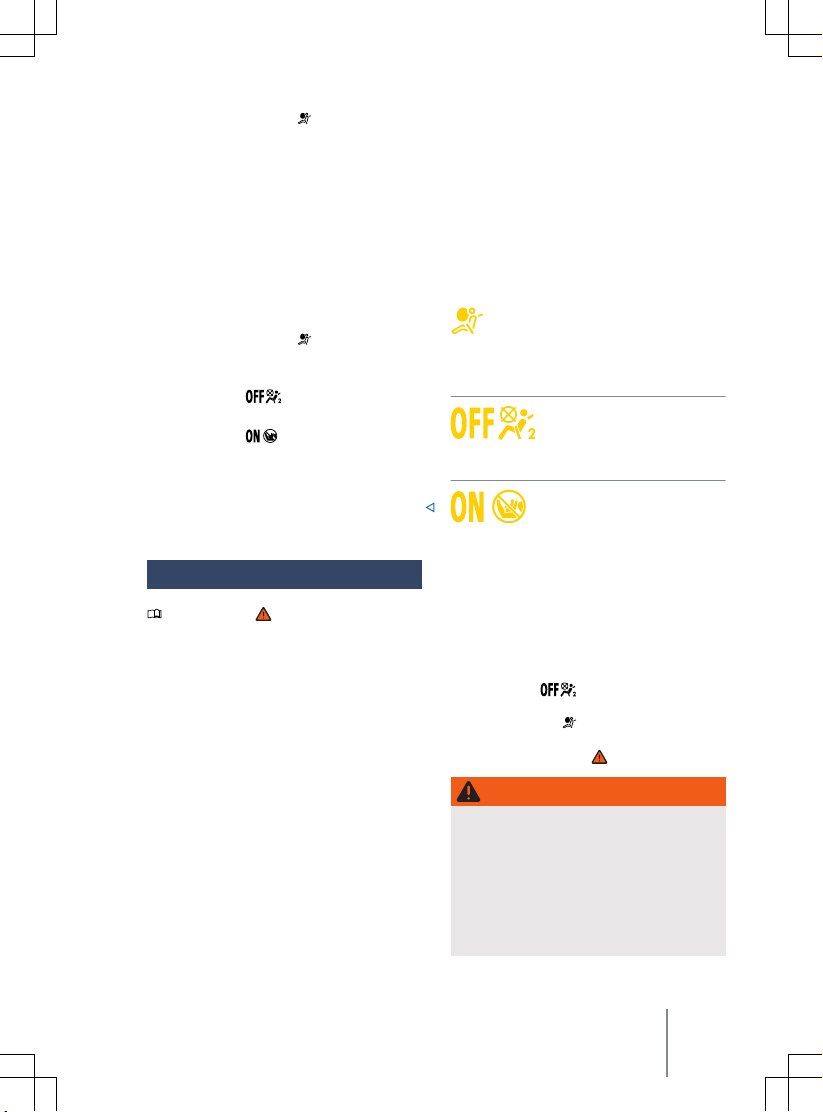
— Yellow indicator lamp in the instrument
cluster display.
Airbag system with front passenger front
airbag deactiv
The front passenger front airbag can be deactivated manually by means of a key-operated
switch → page 53.
Characteristics of the airbag system with
front passenger front airbag deactivation:
— Front passenger front airbag in the dash
panel.
— Yellow indicator lamp
cluster display.
—
Yellow indicator lamp PASSENGER AIR BAG
—
Yellow indicator lamp PASSENGER AIR BAG
—
Key-operated switch in the side of the
dash panel on the passenger side (only
visible when the front passenger door is
open).
ation
in the instrument
in the roof console.
in the roof console.
Indicator lamp
Please refer to at the start of the chap-
ter on page 47.
Fig. 31 In the roof console: indicator lamp
schematic diagram) for deactivated front pas-
(
senger front airbag.
11A012720AB
Fig. 32 In the roof console: indicator lamp
schematic diagram) for activated front passen-
(
ger front airbag.
The yellow indicator lamp in the instrument cluster display lights up
briefly as a functional check when the
ignition is switched on and goes out
after a few seconds.
Front passenger front airbag
switched off
cator lamp in the roof console
lights up continuously → Fig. 31.
Front passenger front airbag
switched on. The yellow indica-
tor lamp in the roof console
will go out automatically appro
mately 60 seconds after the ignition
is switched on or after the front passenger front airbag is switched on using the key-operated switch
→ Fig. 32.
If the front passenger front airbag is switch-
ed off and the yellow PASSENGER AIR BAG
indicator lamp
not light up continuously or lights up together with the yellow indicator lamp in the instrument cluster display, there may be a fault
in the airbag system → .
. The yellow indi-
xi-
in the roof console does
WARNING
If there is a fault in the airbag system, the
airbag may not trigger correctly, may not
trigger at all or may trigger une
This can cause severe or fatal injuries.
The airbag system should be checked by
·
a qualified workshop as soon as possible.
Never fit a child seat on the front pas-
·
senger seat. Remove a fitted child seat!
xpectedly.
Airbag system 49
Page 52
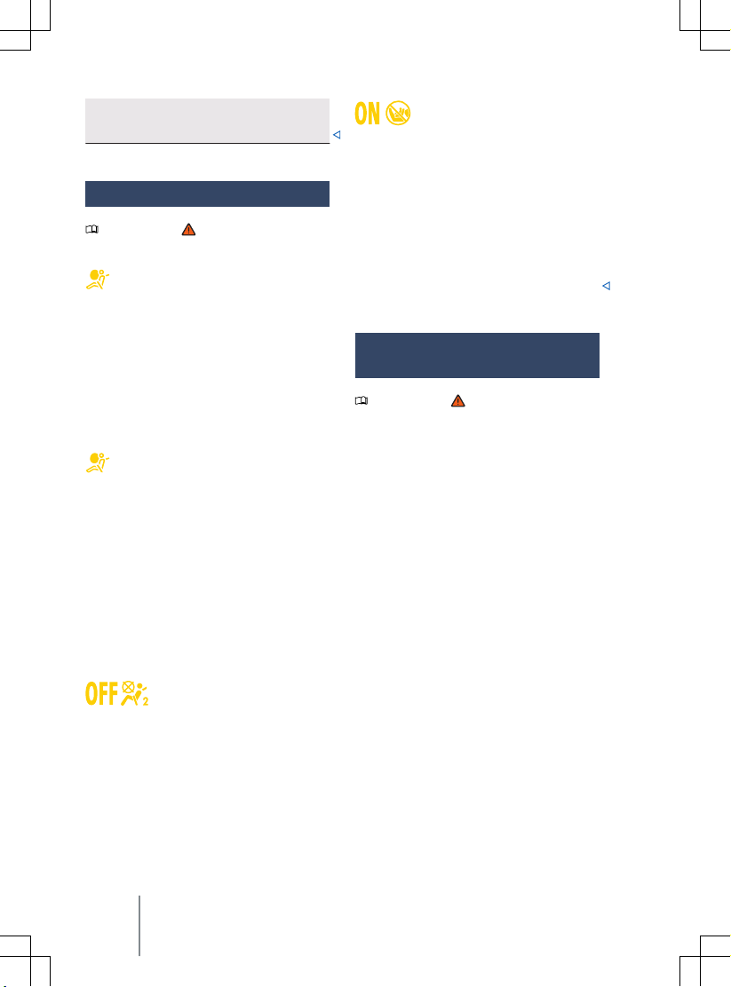
The front passenger front airbag may
trigger during an accident in spite of the
fault.
Troubleshooting
Please refer to at the start of the chap-
ter on page 47.
Fault in airbag or belt tensioner system
The yellow indicator lamp lights up continuously. In addition, a message may be displayed in the instrument cluster.
A malfunction has been detected in at least
one airbag or belt tensioner.
Go to a qualified workshop.
—
— Have the airbag system and belt tensioner
system checked.
Airbag system or belt tensioner system
ated with diagnostic tool
deactiv
The yellow indicator lamp lights up for
around four seconds when the ignition is
switched on and then flashes for around
twelve seconds. In addition, a message may
be displayed in the instrument cluster.
At least one airbag or belt tensioner was deactivated with a diagnostic tool.
— Go to a qualified workshop.
— Have a check carried out to establish
whether the airbag or belt tensioner system must remain switched off.
Front passenger front airbag
switched off
The yellow indicator lamp for the deactivated
front passenger front airbag lights up continuously.
The front passenger front airbag has been
switched off
— Check whether the front passenger front
.
airbag must remain switched off, e.g.
when using a child seat on the front passenger seat.
Front passenger front airbag
switched on
The yellow indicator lamp for the activated
front passenger front airbag lights up f
around 60 seconds after the ignition has
been switched on or after switching on the
front passenger front airbag with the key-operated switch.
The front passenger front airbag has been
switched on.
— Check whether the front passenger front
airbag must remain switched on.
or
Description and function of
the airbags
Please refer to at the start of the chap-
ter on page 47.
The airbags can protect v
during frontal and side collisions by reducing
their movement in the direction of the collision.
When an airbag is triggered, it is inflated by
a gas generator. This causes the airbag covers
to break, and the airbags inflate forcefully to
cover their deployment zones within milliseconds. Once a vehicle occupant wearing a seat
belt starts to sink into the inflated airbag, the
gas inside the airbag starts to escape to
cushion the occupant and slow down their
movement. This can reduce the risk of severe
and fatal injuries. A triggered airbag will not
always prevent other injuries from occurring,
such as swelling, bruising, burning and grazing. The deployment of the airbag can also
produce frictional heat.
Airbags provide no protection for the arms or
lower body.
The most important factors for triggering the
airbag are the type of accident, the angle of
impact, the vehicle speed and the type of object with which the vehicle collides. Therefore, visible damage to the vehicle does not
always mean that the airbag should have
been triggered.
ehicle occupants
50
Safety
Page 53

Whether or not the airbag triggers is determined by the v
ehicle deceleration rate
caused by the collision and registered by the
electronic control unit. If this rate is below
the reference value programmed into the
control unit, the airbags will not be triggered,
even though the vehicle may be badly damaged as a result of the collision. Vehicle damage, repair costs or even the lack of vehicle
damage in an accident do not necessarily
give an indication of whether an airbag
should inflate or not. It is not possible to define a range of vehicle speeds and reference
values, since the circumstances will vary considerably between one collision and another.
It is therefore impossible to cover every possible kind and angle of impact that would
trigger the airbags. Important factors in the
triggering of the airbag include the nature
(hard or soft) of the object that the vehicle
hits, the angle of impact, and the vehicle
speed.
Airbags only serve as a supplement to the
three-point seat belt in some accident situations when the vehicle deceleration is sufficient to trigger the airbags. Airbags can only
be triggered once and only in certain situations. The seat belts are always there to provide protection in situations where airbags
are not normally triggered or where they
have already been triggered, for example if
the vehicle collides with another vehicle after
the first collision or is hit by another vehicle.
The airbag system is part of the vehicle's
overall passive safety concept. The airbag
system can only work effectively when the
occupants are wearing their seat belts correctly and have assumed a proper sitting position
→ page 34.
Components of the v
ehicle safety concept
The following vehicle safety equipment
makes up the vehicle's safety concept to reduce the risk of severe and fatal injuries.
Some of this equipment may not be fitted in
your particular vehicle. It may not be available at all in some countries.
— Optimised seat belts for all seats.
11A012720AB
— Belt tensioners for the driver and front
passenger and also on the rear outer seats
if in conjunction with side airbags.
Belt tension limiter for the driver, front
—
passenger and, if applicable, for the rear
outer seats.
— Red warning lamp
and, where applica-
ble, belt status display.
Front airbags for driver and front passen-
—
ger.
— Side airbags for driver and front passen-
ger.
— Curtain airbags on the left and right.
— Central airbag between driver and front
passenger.
— Yellow airbag indicator lamp
—
Yellow indicator lamp PASSEN-
GER AIR BAG
—
Yellow indicator lamp PASSEN-
GER AIR BAG
—
Control units and sensors.
in the roof console.
in the roof console.
.
— Safety-optimised and height-adjustable
head restraints.
— Adjustable steering column.
— If applicable, anchor points for child seats
on the rear outer seats and on the front
passenger seat.
— If fitted, mounting points for the top teth-
er for child seats.
Situations when the front, side, curtain and
central airbags will not be triggered:
— When the ignition is switched off during
a collision.
— If the level of deceleration measured by
the control unit is too low during a colli-
sion at the front of the vehicle.
— During a slight side collision.
— During a rear-end collision.
— If the dynamics measured by the control
unit are too low in the event of a vehicle
rollover.
Airbag system
51
Page 54
— If the impact speed in a collision is lower
than the ref
control unit.
erence value specified in the
Front airbags
Please refer to at the start of the chap-
ter on page 47.
Fig. 33 Location and deployment zone of the
er front airbag.
driv
Fig. 34 Location and deployment zone of the
front passenger front airbag.
In conjunction with the seat belts, the front
airbag system giv
tional protection for the head and chest in
the event of a severe frontal collision. The
curtain airbags on both sides are also triggered in the event of certain types of frontal
collision.
es the front occupants addi-
Always keep as far away from the front airbag as possible → page 34. This allows the
front airbags to inflate fully when triggered,
thus pro
viding maximum protection.
The front airbag for the driver is located in
the steering wheel → Fig. 33 and the front
airbag for the front passenger is located in
the dash panel → Fig. 34. The airbag locations are identified by the text “AIRBAG”.
The areas inside the red lines are covered by
the front airbags when deployed (deployment
zone). You must never leave or attach any objects in these areas →
accessories will not be struck if the driv
front passenger front airbags are deployed.
. Any factory-fitted
er and
DANGER
Once triggered, the airbag inflates in fractions of a second at v
Always leave the deployment zones of
·
the front airbags clear.
Never attach any objects, such as drink
·
or telephone holders, to the covers of
the airbags or anywhere in the airbag
deployment zone.
There must be no other people, animals
·
or objects between the occupants of the
front seats and the airbag deployment
zones. Ensure that children and adults
keep to this rule.
Do not attach any objects, e.g. mobile
·
navigation devices, to the windscreen
above the front airbag on the front passenger side.
Do not stick things to, cover or other-
·
wise alter the airbag unit in the steering
wheel and the surface of the dash panel
in the deployment zone of the front passenger's airbag.
ery high speed.
WARNING
The front airbags are deployed in front of
the steering wheel → Fig. 33 and dash panel → Fig. 34.
When driving, always hold the steering
·
wheel with both hands on the outside of
Safety
52
Page 55
the ring at the 9 o'clock and 3 o'clock
positions.
Adjust the driv
·
least 25 cm (approximately 10 inches)
between your rib cage and the hub of
the steering wheel. Contact a qualified
workshop if your physical build makes
this impracticable.
Adjust the front passenger seat so that
·
the distance between the passenger and
the dash panel is as large as possible.
er seat so that there is at
Switching the front passenger
front airbag on and off
Please refer to at the start of the chap-
ter on page 47.
Fig. 35 In the dash panel on the front passen-
ger side: key-operated switch f
and activating the front airbag on the front passenger side
The front passenger front airbag must be deactivated if you fit a rear-facing child seat on
the front passenger seat.
Switching on the front passenger front airbag
— Deactivate the vehicle’s drive system.
— Open the door on the front passenger side.
— Remove the spare key from the vehicle
key.
— Insert the key bit of the spare key into the
key-operated switch on the dash panel un-
11A012720AB
til you feel the second point of resistance
or deactivating
→ Fig. 35. Around three quarters of the
key bit should be inserted in the key
switch at this point →
Turn the spare key without using force to
—
the position
Remove the spare key from the key-oper-
—
ated switch and insert it back into the ve-
hicle key →
The yellow P
lamp
goes out after appro
→ page 49.
— Close the door on the front passenger
side.
— Check that the yellow PASSEN-
GER AIR BAG
roof console does not light up when the
ignition is switched on → page 49.
Deactiv
bag
— Switch off the ignition.
— Open the door on the front passenger side.
— Remove the spare key from the vehicle
key.
— Insert the key bit of the spare key into the
key-operated switch on the dash panel un-
til you feel the second point of resistance
→ Fig. 35. Around three quarters of the
key bit should be inserted in the key
switch at this point →
—
Turn the spare key without using force to
the position
Remove the spare key from the key-oper-
—
ated switch and insert it back into the ve-
hicle key →
Close the door on the front passenger
—
side.
The yellow PASSENGER AIR BAG
cator lamp in the roof console lights up continuously when the ignition is switched on
→ page 49.
.
ASSENGER AIR BAG indicator
in the roof console lights up and
ating the front passenger front air-
.
.
.
ximately 60 seconds
indicator lamp in the
.
.
indi-
Airbag system 53
Page 56
Confirmation that the front passenger front
airbag has been deactiv
A deactivated front passenger front airbag is
indicated only by a continuously lit PASSENGER AIR BAG
lights up yellow continuously) → page 49.
If the yellow P
cator lamp does not light up continuously or
lights up together with the yellow indicator lamp in the instrument cluster display, no
child restraint system must be fitted on the
front passenger seat f
front passenger front airbag may trigger during an accident.
ated
indicator lamp (
ASSENGER AIR BAG
or safety reasons. The
indi-
WARNING
The front passenger front airbag should only be switched off in e
stances.
To prevent damage to the airbag sys-
·
tem, only switch the front passenger
front airbag on and off when the ignition
is switched off.
It is the driver's responsibility to ensure
·
that the key-operated switch is set to
the correct position.
Only switch the front passenger front
·
airbag off if, in exceptional circumstances, a child seat has to be attached to
the front passenger seat.
Switch the front passenger front airbag
·
back on again as soon as the child seat
on the front passenger seat is no longer
being used.
xceptional circum-
NOTICE
If the key bit is not inserted far enough, the
key switch could be damaged when the key is
turned.
NOTICE
Do not leave the spare key in the key switch,
as this could result in damage to the door
trim, dash panel, key switch or vehicle key
when the front passenger door is closed.
Side airbags
Please refer to at the start of the chap-
ter on page 47.
Fig. 36 In the interior on the left-hand side of
the vehicle: side airbag deployment zone.
WARNING
Do not leave the spare key inserted in the
key-operated switch while the vehicle is in
motion.
Vibrations in the vehicle could cause the
·
spare key to turn in the key-operated
switch, which could then activate the
front passenger front airbag.
The front passenger front airbag could
·
then accidentally inflate, leading to serious or fatal injuries.
54
Safety
Fig. 37 On the side of the front seat: location
and deployment zone of the side airbag.
Page 57
Side airbags are installed for the front seats
→ Fig. 36. The side airbags are located in the
outer seat backrest cushions of the driv
seat and front passenger seat → Fig. 37.
The locations of the side airbags are indicated by the “AIRBAG” label.
The areas outlined in red are inside the deployment area of the side airbags → Fig. 36
and → Fig. 37. You must never leave or attach
any objects in these areas →
vent of a side collision, the side air-
In the e
bags will be deployed on the side of the vehicle which is impacted, thus reducing the risk
of injury to the areas of the occupants' bodies
facing the impact. The curtain airbags on
both sides are also triggered.
WARNING
Once triggered, the airbag inflates in fractions of a second at v
Always leave the deployment zones of
·
the side airbags clear.
There must be no other people, animals
·
or objects between the occupants of the
front seats and the airbag deployment
zones. Ensure that children and passengers keep to this rule.
The coat hooks in the vehicle should on-
·
ly be used for lightweight clothing. Do
not leave any heavy or sharp objects in
the pockets.
Do not fit any accessories to the doors.
·
Do not fit seat covers or protective cov-
·
ers over the seats unless they have been
expressly approved for use in the vehicle. Otherwise the side airbag may not
be able to inflate once triggered.
ery high speed.
WARNING
Incorrect use of the driver and front passenger seat could hinder the proper function of the side airbag and cause serious injury.
Never remove the front seats from the
·
vehicle or alter any components of these
11A012720AB
seats.
If too much pressure is applied to the
·
er
.
backrest side bolsters, the side airbags
may not be triggered correctly, may not
trigger at all, or may trigger accidentally.
Any damage to the original seat uphols-
·
tery or around the seams of the side airbag units must be repaired immediately
by a qualified workshop.
Curtain airbags
Please refer to at the start of the chap-
ter on page 47.
Fig. 38 On the left-hand side of the v
cation and deployment zone of the curtain airbag.
Curtain airbags are installed in the vehicle interior above the doors on the driver and front
passenger sides → Fig. 38.
The locations of the curtain airbags are indicated by the “AIRBAG” label.
The area in the red frame is covered by the
curtain airbag when triggered (deployment
zone) → Fig. 38. For this reason, you must
never leave or attach any items in this area
→
.
The curtain airbags will be triggered on both
sides if the v
of a frontal or side collision.
In rollovers, side collisions and certain types
of frontal collision, the curtain airbags reduce
the risk of injury for the vehicle occupants on
the front seats and rear outer seats.
ehicle rolls over or in the event
ehicle: lo-
Airbag system
55
Page 58

WARNING
Once triggered, the airbag inflates in fractions of a second at v
Always leave the deployment zones of
·
the curtain airbags clear.
Never secure any items to the cover or in
·
the deployment zone of the curtain airbag.
There must be no other persons, animals
·
or objects between the vehicle occupants sitting on the front seats and rear
outer seats and the deployment zones of
the airbags. Ensure that children and
passengers keep to this rule.
The coat hooks in the vehicle should on-
·
ly be used for lightweight clothing. Do
not leave any heavy or sharp objects in
the pockets.
Do not fit any accessories to the doors.
·
Do not install any sun blinds onto the
·
side windows unless they have been expressly approved for use in your vehicle.
Only push the sun visors over to the side
·
windows if no items are attached to the
visors (e.g. pens or a garage door opener).
ery high speed.
Central airbag
Please refer to at the start of the chap-
ter on page 47.
Fig. 39 In the inner backrest padding of the
er seat: central airbag.
driv
The central airbag is installed for the front
seats and is located in the inner backrest
padding of the driver seat.
The location of the central airbag is indicated
by the “AIRBAG” label → Fig. 39.
The area in the red frame is covered by the
central airbag when triggered (deployment
zone) → Fig. 39. For this reason, you must
never leave or attach any items in this area
→
.
The central airbag is triggered in the e
a side collision and vehicle rollover and thus
reduces the risk of injury to the vehicle occupants.
vent of
WARNING
Once triggered, the airbag inflates in fractions of a second at v
Always leave the deployment zones of
·
the central airbag clear.
Never secure any items on the cover or
·
in the deployment zone of the central
airbag.
There must be no other people, animals
·
or objects between the occupants of the
front seats and the airbag deployment
56
Safety
ery high speed.
Page 59
zones. Ensure that children and passengers keep to this rule.
Do not fit seat co
·
ers over the seats unless they have been
expressly approved for use in the vehicle. Otherwise the central airbag may
not be able to inflate once triggered.
vers or protective cov-
WARNING
Incorrect use of the driver and front passenger seat could hinder the proper function of the central airbag and cause serious
injury.
ver remove the front seats from the
Ne
·
vehicle or alter any components of these
seats.
If too much pressure is applied to the
·
backrest side bolsters, the central airbag
may not be triggered correctly, may not
trigger at all, or may trigger accidentally.
Any damage to the original seat covers
·
or around the seams of the central airbag unit must be repaired immediately
by a qualified workshop.
Safe transport of children
Introduction to the topic
Using child seats can reduce the risk of injury
to the child if there is an accident. Always use
child seats when driving with children.
Note the f
— Child seats are classified into groups de-
— Various securing systems are used to se-
For safety reasons, child seats must always
be fitted to the rear seats → page 59.
Volkswagen recommends child seats from
the Volkswagen range of accessories. These
11A012720AB
ollowing:
pending on the size, age and weight of
child for which they are designed.
cure child seats in the vehicle.
child seats have been developed and appro
ved for use in Volkswagen vehicles.
For further information on the child seats
from the range of accessories, contact
a Volkswagen dealership or visit the Volkswagen website.
WARNING
If children are not secured or are inadequately secured, they are at greater risk of
serious or e
following:
·
·
·
·
·
·
·
ven fatal injury. Please note the
Children who are either under 12 years
of age or less than 150 cm (approximately 59 inches) tall must not be carried in the vehicle unless they are secured in a suitable child seat while the
vehicle is in motion. Regulations in some
countries may differ and must be complied with.
Always secure children in the vehicle in
a suitable child seat. The seat used must
be appropriate to the child's height,
weight and age.
Never fasten more than one child into
one child seat.
Under no circumstances should children
or babies be held in a passenger's or
drivers lap while driving.
Never leave a child unsupervised in
a child seat.
Never allow a child to be carried in a vehicle without being properly secured,
and never allow a child to stand up or to
kneel on a seat, or to sit incorrectly
while the car is in motion. This is particularly important for children carried on
the front passenger seat. In an accident,
children may sustain serious injuries to
themselves and others.
The child seat can only provide maximum protection if the seat belt is routed
correctly around it. Always ensure that
the seat belt is routed as specified in the
instructions provided by the child seat
manufacturer. If the seat belt is routed
Safe transport of children
57
Page 60
incorrectly it may cause injuries even in
a minor accident.
After an accident, it is vital to replace
·
any child seats that were in use during
the accident, as they could ha
tained non-visible damage.
ve sus-
NOTICE
Please observe the notes and information for
ehicles with N1 approval → page 373, Infor-
v
mation about vehicles with N1 approval (light
commercial vehicle).
Types of child seat
Please refer to and at the start of
the chapter on page 57.
Only use child seats that have been officially
approved and are suitable for the child.
Standards for child seats
In the user states, child seats are subject to
the regulations ECE R 44 or ECE
R 129→ page 58, Standards for child seats.
Both regulations apply simultaneously. Child
seats which have been tested in accordance
with these standards carry an orange ECE approval label. This ECE approval label may include the following information on the child
seat:
— Weight class.
— Size class.
— Approval category (universal, semi-univer-
sal, vehicle-specific or i-Size).
— Approval number.
On child seats that are approved under regulation ECE R 44, the eight-digit approval
number on the ECE approval label must begin
with 03 or 04. This shows that the seat is admissible for use. Older child seats with an approval number beginning with 01 or 02 are
not admissible.
Child seat weight classes
Fig. 40 Example illustrations of child seats.
Class Child's weight
Group 0 up to 10 kg
Group 0+ up to 13 kg
Group 1 9 to 18 kg
Group 2 15 to 25 kg
Group 3 22 to 36 kg
— Weight class 0/0+: group 0/0+ or 0/1 rear-
facing infant carriers → Fig. 40 are the
best option f
about 18 months.
— Weight class 1: group 1 (up to about
four years old) and group 1/2 (up to about
seven years old) with an integral belt system are best for children over the relevant
weight limit.
— Weight classes 2/3: groups 2 and 3 in-
clude child seats with a backrest, and
booster seats with no backrest. Child seats
with a backrest have integrated seat routing and side padding, and so provide better protection than booster seats with no
backrest. Volkswagen therefore recommends the use of child seats with a backrest. Group 2 child seats are for children
up to the age of about seven, group 3 child
seats for those older than seven.
Not every child will fit in the child seat specified for their weight group. Likewise, not every seat will fit in every vehicle. Therefore it
is vital to check that the child fits properly in
their child seat and that the child seat can be
securely fastened in the vehicle.
or the period from birth to
58
Safety
Page 61
Child seat approval categories
Child seats can be classified as “univ
“semi-universal” “or vehicle-specific” (all in
accordance with regulation ECE R 44) or “iSize” (in accordance with regulation ECE
R 129).
— Universal: child seats with “universal” ap-
proval are approved for use in all vehicles.
No type list is required. ISOFIX child seats
with universal approval must be additionally secured using a strap over the top of
the vehicle seat (top tether).
— Semi-universal: “semi-universal” approval
requires other safety devices for attaching
the seat (that require additional testing) in
addition to the standard requirements for
universal approval. Child seats with “semiuniversal” approval come with a type list.
The seats should only be used in vehicles
that are included on this list.
— Vehicle-specific: child seats with vehicle
specific approval must have undergone
dynamic testing in each model of vehicle
for which it is approved. These child seats
also come with a type list.
— i-Size: child seats classified as “i-Size”
must conform to the installation and safety requirements prescribed in regulation
ECE R 129. Contact the child seat manufacturer to find out whether child seats are
approved for this vehicle, and if so which
ones, in accordance with i-Size.
Installing and using child
seats
Please refer to and at the start of
the chapter on page 57.
Country-specific regulations
The standards and regulations go
use of child seats and child seat securing
mechanisms differ from country to country.
Not all countries allow you to transport children on the front passenger seat. Regulations
11A012720AB
ersal”,
verning the
and legal requirements take precedence over
ormation given in this owner's manual.
the inf
Information on fitting a child seat
Observe the following general information
when fitting a child seat. This information is
relevant whatever child seat securing system
is being used.
— Read and follow the instructions provided
by the child seat manufacturer →
Whenever possible, fit the child seat on
—
the rear bench seat behind the front pas-
senger seat so that children can exit the
vehicle on the kerb side.
— Set the seat belt height so that the seat
belt routing follows a natural line and is
adjusted to the child seat without turning
back on itself. For rear-facing child seats,
use the lowest position of the belt height
adjuster.
— Deactivate the front passenger front air-
bag if fitting a rear-facing child seat on the
front passenger seat.
— When fitting on the front passenger seat,
push the front passenger seat back fully
and adjust the seat to the highest position.
Adjust the backrest to an upright position
→ page 34.
— Always ensure that there is enough space
around the child seat. If necessary, adjust
the position of the seat in front. When do-
ing so, ensure that the driver or front pas-
senger can still maintain a correct sitting
position → page 34.
— The backrest of the child seat must lay as
flat as possible against the vehicle seat
backrest. If required, adjust the seat back-
rest angle so that the child seat lies flush
against the backrest. Once it has been in-
stalled, if the child seat is touching the
head restraint and therefore cannot be
positioned flush against the backrest, push
the head restraint all the way up, or re-
move and stow safely in the vehicle
→ page 34.
.
Safe transport of children
59
Page 62
Airbag sticker
Fig. 41 Illustration: airbag label on the sun vi-
sor.
Fig. 42 Illustration: airbag label on the B-pillar.
The v
ehicle may be provided with stickers
giving important information about the front
passenger front airbag. The information on
these stickers may vary from country to
country. The stickers may be found:
— On the driver sun visor and in some cases
on the front passenger sun visor → Fig. 41.
— On the B-pillar on the front passenger side
→ Fig. 42.
It is essential to observe the warning information shown on these stickers before installing a rear-facing child seat →
volved in carrying children on the
Risks in
front passenger seat
If you are using a rear-facing child seat, the
front passenger front airbag can cause critical
or potentially fatal injuries when it inflates
→
.
Rear-facing child seats may be used on the
front passenger seat only if the front passenger front airbag has been deactiv
.
ated
→ page 47. A deactivated front passenger
front airbag is indicated by means of the continuously lit P
lamp
→ page 49.
If using a front-facing child seat, do not deactiv
When fitting the child seat, ensure that it is
as far away as possible from the front passenger front airbag. The front passenger
front airbag can cause severe injuries when it
inflates →
Some child seats are not suitable f
the front passenger seat. The child seat must
be specially authorised by the manufacturer
for use on the front passenger seat in vehicles with front and side airbags. Volkswagen
dealerships keep an up-to-date list of authorised child seats.
ASSENGER AIR BAG indicator
in the driver's field of vision
ate the front passenger front airbag.
.
or use on
DANGER
If you use a rear-facing child seat on the
front passenger seat, the child in it is at increased risk of sustaining critical or fatal injuries in the e
Deactivate the front passenger front air-
·
bag. If the front passenger front airbag
cannot be deactivated no rear-facing
child seat may be used.
Move the front passenger seat as far
·
back and as high as it can be adjusted to
create the largest possible distance between the child seat and the front passenger front airbag.
Move the backrest to the upright posi-
·
tion.
Set the seat belt height so that the seat
·
belt routing follows a natural path adapted to the child seat without excessive
deviations. For rear-facing child seats,
use the lowest position of the belt
height adjuster.
Only use child seats that have been ap-
·
proved by the child seat manufacturer
for use on a front passenger seat with
front and side airbag.
vent of an accident.
60 Safety
Page 63
WARNING
Child seats present a risk of injury if incorrectly installed.
Always read and f
·
instructions and warning information
provided by the child seat manufacturer.
ollow the installation
WARNING
Using a front-facing child seat on the front
passenger seat presents a risk of injury.
Move the front passenger seat as far
·
back and as high as it can be adjusted to
create the largest possible distance between the child seat and the front passenger front airbag.
Move the backrest to the upright posi-
·
tion.
Set the seat belt height so that the seat
·
belt routing follows a natural path adapted to the child seat without excessive
deviations. For rear-facing child seats,
use the lowest position of the belt
height adjuster.
Only use child seats that have been ap-
·
proved by the child seat manufacturer
for use on a front passenger seat with
front and side airbag.
WARNING
To avoid injuries caused by inflation of
a head airbag or side airbag:
Ensure that no children are seated with-
·
in the airbag deployment zones
→ page 47.
Do not place any objects in the side air-
·
bag deployment zones.
11A012720AB
Securing systems
Please refer to and at the start of
the chapter on page 57.
Diff
erent countries use different securing
systems for safely fitting child seats in the
vehicle.
Overview of securing systems
— ISOFIX: ISOFIX is a standardised securing
system for fitting child seats in the vehicle
quickly and safely. The ISOFIX attachment
system creates a rigid connection between
the child seat and the car body.
The seat has two rigid attachment arms. The
attachment arms engage in ISOFIX attachment points between the seat and the backrest→ page 62. Atop tether or a support
bracket may sometimes be used in addition
to the ISOFIX anchor points described above.
— Three-point automatic seat belt. It is bet-
ter to secure child seats using the ISOFIX
system, if available, rather than with
a three-point automatic seat belt
→ page 65.
Additional securing points:
— Top tether: the strap at the top of the
child seat is routed over the rear seat
backrest and hooked to an anchor ring on
the back of the rear seats → page 64. Top
tether anchor points are marked with an
anchor symbol.
— Support foot: some child seats are suppor-
ted by a support foot resting on the floor
of the vehicle. This support foot helps prevent the child seat tipping forward in
a crash. Child seats with a support foot can
only be used on the front passenger seat
and the outer rear seats →
Recommended child seat securing systems
V
olkswagen recommends that child seats are
secured as follows:
— Infant carrier or rear-facing child seat:
ISOFIX and support foot.
.
Safe transport of children
61
Page 64
ront-facing child seat: ISOFIX and top
— F
tether and possibly also support foot.
Applies only in Australia:
WARNING
WARNING
Incorrect use of the support foot can cause
vere or fatal injuries.
se
Ensure that the support foot is always
·
correctly and safely installed.
Child restraint anchorages are designed to
withstand only those loads imposed by correctly fitted child restraints. Under no circumstances are they to be used f
seatbelts, harnesses, or for attaching other
items or equipment to the vehicle.
Securing a child seat with ISOFIX/i-Size
Please refer to and at the start of the chapter on page 57.
Quick guide to ISOFIX and i-Size installation
The identification marking of the ISOFIX or iSize anchorage points is equipment and
country dependent.
The following table shows the installation
or ISOFIX or i-Size child seats at the
options f
ISOFIX or i-Size anchorage points of the individual vehicle locations.
or adult
Group
Group 0: up to
10 kg
Group 0+: up to
13 kg
Group 1: 9 to 18 kg
Group 2: 15 to
25 kg
Group 3: 22 to
36 kg
i-Size child restraint system
Booster seat
62 Safety
Orienta-
tion of
the child
seat
Rear facing
Rear facing
Rear facing
Forward
facing
Forward
facing
Forward
facing
Rear facing
Forward
facing
Forward
facing
Front passenger seat
Size
Front pas-
class /
ISOFIX
class
E/R1 X IL-SU IL-SU X
E/R1
C/R3
D/R2
C/R3
B/F2X
A/F3
–/R2 X i-U i-U X
–/B2,
F2X
–/B2, B3 i-B X i-B X
senger
front air-
bag activ
IL-SU, IUF X IL-SU, IUF XB1/F2X
– IL-SU X IL-SU X
– IL-SU X IL-SU X
Front pas-
senger
front air-
a-
bag deacti-
ted
X IL-SU IL-SU XD/R2
X IL-SU IL-SU X
i-U X i-U X
vated
Outer seats
on the rear
bench seat
Centre
seat on
the rear
bench
seat
Page 65

— Size class: the size class shown corre-
sponds to the permissible weight range of
the child using the seat. The size class is
indicated on the ECE appro
val label for
child seats with “universal” or “semi-universal” approval. A size class indication is
affixed to the child seat.
— X: seat not suitable for securing an ISOFIX
or i-Size child seat in this group.
— IL-SU: seat suitable for installing an ISOFIX
child seat with “semi-universal” approval.
Refer to the vehicle list supplied by the
child seat manufacturer.
— IUF: seat suitable for installing an ISOFIX
child seat with “universal” approval.
— i-U: seat suitable for installing a front-fac-
ing or rear-facing i-Size child seat with
“universal” approval.
— i-UF: seat suitable for installing a front-
facing i-Size child seat with “universal” approval.
— i-B: seat suitable for installing a forward-
facing ISOFIX booster seat of Group 2/3 as
well as a forward-facing i-Size child seat
for children with a height of 100 – 150 cm
(approximately 39 – 59 inches).
Installing child seats with ISOFIX/i-Size
Fig. 44 Markings identifying the i-Size anchor-
age points f
bench seat.
Fig. 45 Markings identifying the i-Size anchorage points f
seat.
or child seats on the seats of the rear
or child seats on the front passenger
Fig. 43 Markings identifying the ISOFIX anchorage points f
bench seat.
11A012720AB
or child seats on the seats of the rear
Fig. 46 Illustration: fitting a child seat with the
attachment arms.
The location of the ISOFIX or i-Size anchorage
points is indicated by a symbol → Fig. 43,
→ Fig. 44 or → Fig. 45.
—
Observe the instructions → page 59.
Safe transport of children
63
Page 66

— Fold down any protective caps that may
be fitted on the ISOFIX or i-Size anchor
points.
Push the attachment arms of the child
—
seat in the direction of the arrow onto the
ISOFIX or i-Size anchorages → Fig. 46. The
child seat must click and audibly securely
into place.
Securing child seats with the
top tether
Please refer to and at the start of
the chapter on page 57.
— Perform a pull test on both sides of the
child seat to check that the child seat is
properly engaged.
If the child seat is fitted with a support foot,
the foot must stand firmly on the floor of the
vehicle.
Fig. 47 In the luggage compartment: attached
top tether.
64 Safety
Fig. 48 On the rear of the front passenger seat:
attached top tether.
Page 67
Fig. 49 In the backrest of the Top sports seat
on the passenger side: opening for the top tether
(schematic diagram).
1
Opening for the top tether.
ISOFIX child seats with “universal” approval
must be secured with an upper strap (
tether) in addition to the ISOFIX anchor
points.
Only secure the strap to the top tether anchor rings provided for this purpose. Anchor
rings for use with the top tether are marked
by a symbol and sometimes also with “TOP
TETHER”.
— Observe the instructions → page 59.
— Push the head restraint on the vehicle seat
all the way up or remove it.
— Position the child seat in the centre of the
seat cushion.
top
— Push the attachment arms on the child
seat into the ISOFIX anchor points as
shown by the arrows→ page 62. The child
seat must click and audibly securely into
place.
—
Remove the luggage compartment cover if
necessary.
— Only applies to the Top sports seat: Feed
the top tether through the opening in the
backrest → Fig. 49
—
Guide the top tether of the child seat to
the rear over the seat and hook it into the
corresponding anchor ring labelled “top
tether” .
— Tighten the upper strap so that the top of
the child seat rests against the rear seat
backrest.
1 .
WARNING
Only secure the strap to the top tether anchor rings pro
to do this could lead to severe injuries.
Each anchor ring can hold only one child
·
seat restraining strap.
Never fasten the strap on a child seat to
·
any other fastening rings.
in the luggage compartment behind the rear
seat backrest.
vided for this purpose. Failure
Depending on the market and model,
there may be two or three anchor rings
Securing a child seat using the seat belt
Please refer to and at the start of the chapter on page 57.
If you want to fit a child seat from the “uni-
ersal” (u) approval category in your vehicle,
v
you must first ensure that it is approved for
the seat position in question. Relevant infor-
11A012720AB
mation is given on the orange ECE approval
label of the child seat. Installation options are
shown in the table below.
Safe transport of children
65
Page 68

Front passenger seat
Group
Group 0 up to 10 kg x u u
Group 0+ up to 13 kg x u u
Rear facing 9 to 18 kg x u u
Group 1
Forward facing 9 to 18 kg u x u
Group 2 15 to 25 kg u x u
Group 3 22 to 36 kg u x u
u: universal; x: seat not suitable for securing a child seat of this group.
Securing a child seat using the seat belt
Observe the instructions → page 59.
—
— Set the seat belt height so that the seat
belt routing follows a natural line and is
adjusted to the child seat without turning
back on itself. For rear-facing child seats,
use the lowest position of the belt height
adjuster.
— Fasten the seat belt and guide it through
the child seat as described in the child seat
manufacturer's instructions.
— Ensure that the seat belt is not twisted.
Child's
weight
Front passenger
front airbag acti-
ated
v
— Insert the latch plate into the buckle for
Child seats with the approval category “semiuniversal” that are secured using a seat belt
and support foot must not be fitted on the
middle seat of the rear bench seat.
If a child seat of Group 2/3 with backrest is
used, additionally use the fourth anchorage
point of the child seat for the seat belt. Observe the instructions for use of the child
seat.
Front passenger
front airbag deac-
tivated
the appropriate seat and push it down until it audibly engages.
Seats on the
rear bench
seat
In an emergency
Making you and your vehicle
saf
e
Observe any legislation concerning the safety
of a broken-down vehicle. For example, many
countries stipulate that you have to switch on
the hazard warning lights and wear a highvisibility waistcoat → page 68.
Checklist
To ensure your own safety and that of your
passengers, observ
the specified order →
Stop the vehicle at a safe distance away
1.
from moving traffic and on a suitable
surface.
2. Depress and hold the brake pedal.
66
e the following points in
:
Safety
3. Switch on the hazard warning lights
→ page 10.
Switch on the electronic parking brake
4.
→ page 177. The vehicle’s drive system
is deactivated.
5. Deactivate the vehicle’s drive system
→ page 138. The red indicator
lights up in the digital instru-
lamp
ment cluster.
6.
Take your foot off the brake pedal.
7. Ensure that all occupants exit the vehicle
and go to a safe place away from moving
traffic, e.g. behind the safety barrier.
Take all vehicle keys with you. Observe
the country-specific regulations concerning high-visibility waistcoats.
8. Set up the warning triangle to draw the
attention of other road users to your vehicle.
Page 69
9. Seek expert assistance if necessary.
When the hazard warning lights are switched
or example if you are being towed, you
on, f
can still indicate a change in direction or lane
change by operating the turn signal. The hazard warning lights will be interrupted temporarily.
Comply with the important information on
towing → page 304.
Switch on the hazard warning lights, e.g. in
the following situations:
— When traffic ahead suddenly slows down
or you reach the tail end of a traffic jam to
warn vehicles behind you.
— When there is an emergency.
— If the vehicle breaks down.
— When the vehicle is being towed.
Always follow local regulations for the use of
the hazard warning lights.
If the hazard warning lights are not working,
you must use an alternative method of drawing attention to the broken-down vehicle.
This method must comply with traffic legislation.
WARNING
Any broken-down vehicle poses a high accident risk f
other road users.
·
·
·
·
11A012720AB
or the vehicle occupants and
Stop the vehicle as soon as possible and
when safe to do so.
Park the vehicle at a safe distance from
moving traffic.
Switch on the hazard warning lights.
Never leave other persons alone in the
vehicle, particularly children or people
requiring assistance. This applies in particular when the doors are locked. People locked in the vehicle may be subjected to very high or very low temperatures.
WARNING
Ignoring any of the items on this important
ety checklist can lead to accidents and
saf
severe injuries.
Follow the actions in the checklist and
·
observe the general safety procedures.
NOTICE
When pushing the vehicle by hand, do not
press on the rear lights, the rear spoiler or
large panels. This could damage the vehicle
and loosen the rear spoiler.
The 12-volt vehicle battery will discharge if the hazard warning lights are
ver a long period of time – even
left on o
when the ignition is switched off.
Depending on the vehicle equipment,
the brake lights flash in quick succession if you brake sharply or initiate full braking at a speed of more than 80 km/h (about
50 mph). This provides an especially conspicuous warning for the following traffic. If you
then continue to brake, the hazard warning
lights will be switched on automatically at
speeds under approximately 10 km/
h (6 mph). Once the vehicle starts to accelerate, the hazard warning lights will switch off
again.
What to do in the event of an
accident or a fire
Checklist of what to do after an accident
To ensure your own safety and that of your
passengers in an accident, observ
lowing actions in the specified order →
✓ Deactiv
✓ Switch on the hazard warning lights
✓ Set up the warning triangle to draw the
ate the vehicle’s drive system.
→ page 13.
attention of other road users to your vehicle.
e the fol-
:
In an emergency 67
Page 70

✓ If necessary, remo
the hazard area and provide first aid.
✓ Report the accident to the fire service.
Inform the fire service that the vehicle in
question has an electric drive.
✓ Wait for the emergency services at the
scene of the accident.
✓ Inform the emergency services and the
persons involved at the scene of the accident that it is an electric vehicle.
Checklist of what to do in the event of a fire
To ensure your own safety and that of your
passengers in the e
serve the following actions in the specified
order →
✓ Deactiv
✓ Switch on the hazard warning lights if
✓ If possible, place the warning triangle in
✓ If necessary, remove all persons from
✓ Report the fire to the fire service. Inform
✓ Wait for the emergency services at
✓ Inform the emergency services and the
✓ Do not attempt to extinguish the fire
✓ Do not remain near the burning vehicle.
:
ate the vehicle’s drive system.
possible → page 13.
position to draw the attention of other
road users to your vehicle.
the hazard area and provide first aid.
the fire service that the vehicle in question has an electric drive.
a safe distance.
persons involved at the scene of the accident that it is an electric vehicle.
yourself.
ve all persons from
vent of a vehicle fire, ob-
WARNING
In the event of a fire, an explosion and
leaking hazardous substances can cause serious injuries.
ver remain near the burning vehicle.
Ne
·
If the system detects that an accident
has happened, the high-
tery is automatically deactivated.
— When the high-voltage battery is deacti-
vated, go to a qualified workshop to have
the high-voltage battery serviced.
voltage bat-
Emergency equipment
First-aid kit
Depending on the v
first-aid kit may be located in a stowage
compartment or a holder in the luggage compartment, under the luggage compartment
floor or in the vehicle interior.
The first-aid kit must comply with legal requirements. Please observe the use-by date
of the contents.
After use, renew contents if necessary and
stow the first-aid kit safely again.
Warning triangle
ehicle equipment, the
WARNING
Ignoring any of the items on this important
ety checklist can lead to accidents and
saf
severe injuries.
Follow the actions in the checklist and
·
observe the general safety procedures.
68 Safety
Fig. 50 In the boot lid: holder f
triangle.
Depending on the equipment, the warning
triangle may be located in the boot lid. With
or the warning
Page 71

the boot lid open, grasp the warning triangle
at the recess and turn by 90° towards the
front of the v
ing triangle through the opening.
The warning triangle must comply with legal
requirements.
Return the warning triangle to its holder after
use.
High-visibility waistcoat
Depending on the vehicle equipment, the
high-visibility waistcoat may be located in
a stowage compartment in the front door
trim or in the glove box → page 9, → page 14.
The high-visibility waistcoat must comply
with legal requirements.
Fire extinguisher
Depending on the vehicle equipment, a fire
extinguisher may be located in a holder in the
footwell under the front passenger seat.
The fire extinguisher must comply with legal
regulations, must always be ready for use and
must be checked regularly (see inspection
seal on the fire extinguisher).
ehicle. Then remove the warn-
WARNING
In the event of a sudden driving or braking
manoeuvre or accident, loose objects could
be flung though the v
vere injuries.
Always secure the first-aid kit, warning
·
triangle and fire extinguisher safely in
the holders in the vehicle.
Stow the high-visibility waistcoat in
·
a stowage compartment so that it is
easily accessible.
11A012720AB
ehicle and cause se-
Legally required eCall Emergency System
Fig. 51 In the roof console: control f
required eCall Emergency System (behind button
cover).
Statutory eCall emergency call system.
Fig. 52 Control f
lamp and button.
1
Indicator lamp.
2
Button for legally required eCall Emergency System.
Depending on the equipment and country,
the vehicle may be equipped with an emergency call system. In some countries, the free
legally required eCall Emergency System is
activated as standard. The control unit is in
the roof console.
The emergency call function enables help to
be organised as quickly as possible in danger-
or emergency call: indicator
or legally
In an emergency 69
Page 72
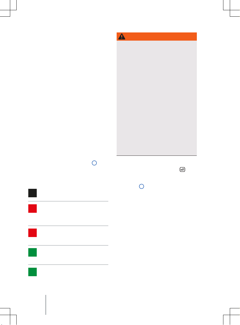
ous situations. A voice connection is established with a public emergency call centre.
The call centre communicates in the language of the country in which the v
located. In addition, legally required data relevant for the emergency call are transmitted
automatically to the public emergency call
centre, such as the current vehicle position.
The legal basis for data processing by the legally required eCall Emergency System corresponds to the country-specific legislation
such as the EU Regulation 2015/758. Please
also observe the information on data storage
and services → page 366.
The required connection is established by
a factory-fitted control unit. Additional components are required in order to ensure that
the function is still possible even after a serious accident, e.g. emergency call microphone, emergency loudspeaker and an integrated battery that is independent of the vehicle electrical system.
Indicator lamp for the statutory eCall Emergency System
There is an indicator lamp → Fig. 52
control. Depending on the operational status
of the emergency call system in the v
the indicator lamp lights up in different colours and light sequences:
Indicator lamp does not light up:
emergency call is not available.
Indicator lamp flashes red for about
20 seconds after the ignition has been
switched on: emergency call is deactiv
ated.
Indicator lamp lights up red continuously: system error. Emergency call is
restricted or not a
Indicator lamp lights up green: emergency call is a
for operation in the vehicle.
Indicator lamp flashes green: emergency call is activ
vailable, system is ready
e.
ehicle is
1 in the
ehicle,
vailable.
WARNING
The following conditions may limit or pre-
ent the execution of a manual or automat-
v
ic emergency call:
Your current emergency call location is
·
in an area with no or insufficient mobile
communications and GPS reception.
No 2G/3G mobile communications net-
·
work of telecommunication providers is
available in areas with sufficient mobile
communications and GPS reception.
The emergency call system is not availa-
·
ble in some countries.
The public emergency call centre is
·
technically not able to receive emergency call data.
The components in the vehicle required
·
for the manual or automatic emergency
call are damaged or do not have sufficient electrical power.
The ignition of the vehicle is not switch-
·
ed on.
Initiating an emergency call manually
Briefly press on the button cover
—
old open the button cover.
f
— Press and hold the emergency call button
→ Fig. 52
emergency call is now initiated and a v
connection is established to the public
emergency call centre.
If you have accidentally pressed the emergency call button, cancel the emergency call
immediately.
— Press the emergency call button again un-
til the indicator lamp lights up green continuously.
Automatic emergency call
An automatic emergency call is initiated only
when the ignition is switched on.
A connection to the public emergency call
centre is established when the airbags or belt
tensioners have been triggered. The automatic emergency call cannot be cancelled by
2 for several seconds. The
and
oice
70
Safety
Page 73
pressing the emergency call button
→ Fig. 52 2 .
Rescue measures will be initiated automatically if there is no response to questions from
the public emergency call centre.
Integrated battery
The integrated battery ensures that the legally required eCall Emergency System remains
vailable for some time if the 12-volt vehicle
a
battery is disconnected or faulty.
A corresponding message will be displayed in
the instrument cluster display if the integrated battery is discharged or faulty. If this
message is displayed, immediately go to
a qualified workshop and have the integrated
battery replaced.
Have the integrated battery checked
by a qualified workshop after about
3 years and replaced if necessary.
Data transmission
In the event of an emergency call, the legally
prescribed data are transmitted to the public
emergency call centre in order to determine
necessary rescue measures.
The data on the vehicle location are continuously overwritten so that only the last three
stored locations required for correct functioning of the legally required eCall Emergency System are available. The vehicle is therefore not permanently tracked.
The data relating to the emergency call are
processed exclusively in order to ensure correct functioning of the legally required eCall
Emergency System. The data related to the
emergency call are automatically deleted
from the system 13 hours after the emergency call was triggered.
The transmitted data include the following:
— Current position of the vehicle when the
emergency call was triggered.
— Two other positions shortly before the
emergency call was triggered (route driven, a few 100 m or around 328 ft).
— Vehicle identification number (VIN).
11A012720AB
— Type of vehicle drive.
—
Vehicle type.
— Type of trigger (automatic or manual)
— Type of call.
— Direction in which the vehicle was moving
when the emergency call was triggered.
— Time of collision.
— Reliability of positioning data.
— Data record version.
— Counter of data strings transferred per
call.
— Estimated number of passengers.
The function of the legally required
eCall Emergency System may be restricted if Infotainment systems have been
retrofitted.
Troubleshooting
Fault in legally required eCall Emergency System
The indicator lamp in the emergency call button lights up red continuously . In addition,
the message
visit workshop.
ment cluster display.
There is a system fault in the legally required
eCall Emergency System. It is not possible to
make an emergency call.
— Drive immediately to a qualified workshop.
— Have the fault rectified.
Legally required eCall Emergency System restricted
The indicator lamp in the emergency call button lights up red continuously . In addition,
the message
Please visit workshop.
strument cluster display.
The function of the legal emergency call system eCall is only available to a limited extent.
It is not possible to make an emergency call.
Error: Emergency call function. Please
may be displayed in the instru-
Emergency call function restricted.
may be displayed in the in-
In an emergency 71
Page 74

— Drive immediately to a qualified workshop.
Have the fault rectified.
—
72 Safety
Page 75
Opening and closing
ehicle key
V
high or very low temperatures depending on the season. This can cause serious
injuries and illness or fatalities, especially among small children.
Functions of the vehicle key
Fig. 53 Vehicle key.
1
Unlock the vehicle. All turn signals flash
twice.
2
Unlock only the boot lid. All turn signals
flash twice. To do this, press and hold
the button briefly.
3
Lock the vehicle. All turn signals flash
once.
4
The indicator lamp flashes when the
button is pressed if all doors and the
boot lid are closed.
WARNING
Careless or unsupervised use of the vehicle
key can lead to accidents or injuries.
ehicle keys with you when you
Take all v
·
leave the vehicle. Children or unauthorised persons could otherwise lock the
doors and boot lid, activate the vehicle’s
drive system or switch on the ignition
and thus operate electrical equipment,
such as the electric windows.
Never leave children or people requiring
·
assistance alone in the vehicle. They
could become trapped in the vehicle in
an emergency and may not be able to
get themselves to safety. For example,
11A012720AB
locked vehicles may be subjected to very
NOTICE
Protect the key from moisture and excessive
vibration.
Spare key
Fig. 54 Vehicle key: releasing the spare key.
1
Press the release button briefly. The key-
olds open.
ring f
2
Press the release button and pull the
spare key out in the direction of the arrow.
3
Spare key.
A spare key → Fig. 54 3 is located in the vehicle key which can be used to lock and unlock the v
ehicle manually → page 73.
Vehicle key 73
Page 76

Changing the button cell
Fig. 55 V
ehicle key: opening battery compart-
ment cover.
ehicle key: replacing the button cell.
Fig. 56 V
Volkswagen recommends having the button
cell changed at a Volkswagen dealership or
by a qualified workshop →
—
Remove the spare key → Fig. 55 1
→ page 73.
— Insert the spare key in the slot → Fig. 55
2 , press in the direction of the arrow and
lever off the cover.
— Lever the button cell out of the battery
compartment → Fig. 56.
— Press the new button cell into the battery
compartment → .
— Press the cover onto the housing
→ Fig. 55.
— Put the spare key back → page 73.
— Dispose of discharged batteries in an envi-
ronmentally responsible way.
.
DANGER
If button cell batteries are swallowed or get
into the wind pipe, this can lead to serious
ven fatal injuries due to suffocation or
or e
internal burns within a very short space of
time.
Call for medical help immediately if you
·
suspect that someone has swallowed
a button cell battery.
If the battery cover cannot be closed, do
·
not use the remote control.
Always keep the remote control and key
·
fob with button cells out of the reach of
children.
NOTICE
ehicle key can be damaged if the
The v
·
button cell is not changed properly.
Unsuitable batteries can damage the vehi-
·
cle key. Replace discharged batteries only
with new batteries of the same voltage
rating, size and specification.
Pay attention to the correct polarity when
·
inserting the battery.
The type of batteries used in the re-
mote control of your v
contain perchlorate. This may require special
handling. Please observe all the legal requirements regarding the handling and disposal of
these batteries. We recommend that you
have this service carried out by a Volkswagen
dealership or a qualified workshop.
ehicle key may
Synchronising the vehicle key
If you cannot lock or unlock the v
the vehicle key, synchronise the vehicle key
or replace the button cell → page 74.
Synchronising the vehicle key:
— Stand beside the vehicle.
— Press the
twice in quick succession.
button on the vehicle key
ehicle with
74 Opening and closing
Page 77

OR:
Remove the spare key → page 73.
—
— If necessary, remove the cover of the driv-
er door handle→ page 80.
— Press the
Unlock the vehicle using the spare key.
—
— Open the driver door. If the vehicle has an
anti-theft alarm, this will be triggered immediately → page 83.
— Switch on the ignition. Please note: to
switch on the ignition, place the vehicle
key in the drink holder or the stowage
compartment in the centre console
→ page 139.
The synchronisation process is complete.
button on the vehicle key.
Troubleshooting
Vehicle cannot be locked or unlocked
The remote control is subject to interference
caused by obstacles, adverse weather conditions or other transmitters operating in the
same frequency range in the vicinity of the
vehicle, e.g. mobile devices, or due to a weak
or flat button cell.
OR: the central locking system has switched
itself off temporarily to protect itself against
overloading.
— Close the driver door.
— OR: synchronise the vehicle key
→ page 74.
— OR: change the button cell in the vehicle
key → page 74.
Indicator lamp does not flash
If the indicator lamp in the vehicle key does
not flash when pressing the button, the button cell in the vehicle key has to be replaced
→ page 74.
Additional or replacement vehicle keys
can be obtained from a Volkswagen
dealership.
11A012720AB
Keyless locking and starting system “Keyless Access”
Introduction to the topic
The Keyless Access function allows the v
cle to be unlocked and locked without actively using the vehicle key. For this purpose,
a valid vehicle key must be within close range
of the vehicle.
Unlocking or locking the vehicle with Keyless Access
Fig. 57 In the door handle: sensors.
Fig. 58 Keyless Access: operating ranges.
Configuring Keyless Access
viour of the keyless access locking
The beha
and starting system Keyless Access can be
ehi-
Keyless locking and starting system “Keyless Access”
75
Page 78
Vehicle
set in the
system.
If the Keyless Access function is deactivated,
the functions of the system may be restricted.
Unlocking the vehicle
—
Touch the sensor → Fig. 57
side of the door handle. All turn signals
flash twice.
The entire v
is touched twice.
Unlocking the vehicle when approaching
The vehicle can be unlocked as you approach
it. For this, the function must be activated in
the Infotainment system and the vehicle key
must be located in the operating range of the
vehicle.
— The vehicle is unlocked if the vehicle key is
detected within the operating range
→ Fig. 58. All turn signals flash twice.
The “Unlock vehicle when approaching” function is deactivated if the vehicle is not unlocked for a longer period of time. The function is re-activated with the next locking action.
If single door unlocking is activated in the
central locking settings in the Infotainment
system, there may be restrictions with
the“Unlock vehicle when approaching” function.
Locking the vehicle
— Park the vehicle.
—
Touch the sensor → Fig. 57
side of the door handle. All turn signals
flash once.
The unlocking function is deactiv
a few seconds so that you can check that
the vehicle has been locked successfully.
Unlocking the boot lid
When the vehicle is locked, the boot lid will
be unlocked automatically if you open it
when a vehicle key is located within the op-
menu in the Infotainment
A on the in-
ehicle is unlocked if the sensor
B on the out-
ated for
erating range of the boot lid. The boot lid will
be locked again after closing.
Please note: When "Central locking, all doors"
and "Keyless Access unlocking when approaching" are activated in the Infotainment
system, the vehicle remains unlocked after
the boot lid has been opened and closed . The
vehicle must be actively locked.
Temporarily deactivating Keyless Access
The Keyless Access unlocking function can be
deactivated temporarily:
— Lock the vehicle with the
v
ehicle key.
— Touch the sensor on the outside of the
door handle once within five seconds
→ Fig. 57
the door handle when doing this. Keyless
Access is now temporarily deactiv
— You can check that it is deactivated by
waiting for at least ten seconds and then
pulling the door handle. It should not be
possible to open the door.
When the vehicle is next unlocked, it can be
unlocked electronically with the vehicle key
only. Keyless Access is reactivated the next
time the vehicle is unlocked →
P
ermanently deactivating Keyless Access
Keyless Access can be permanently deactivated in the Infotainment system →
B . Do not put your hand around
button on the
ated.
.
.
NOTICE
When Keyless Access is deactivated, depending on equipment, the sensor-controlled
opening and closing of the boot lid
→ page 87 is also deactiv
function is active in the vehicle menu.
ated even it the
Troubleshooting
Keyless Access does not work
The function of the door handle sensors may
be restricted if they become v
— Clean the sensors.
ery dirty.
Opening and closing
76
Page 79
All turn signals flash four times
ehicle key used last is still in the vehicle.
The v
— Remove the key and lock the vehicle.
Automatic deactivation of the sensors
The sensors will be deactivated in the following circumstances:
— The vehicle is not unlocked or locked for
an extended period.
— A sensor has been triggered an excessive
number of times.
Activating sensors again:
— Unlock the vehicle with the
the v
ehicle key.
button in
NOTICE
Please note that the sensors in the handles
could be activ
or steam if a valid remote control key is within the operating range. If at least one window
is open and the sensors in a door handle are
continuously activated, all windows will
close. All windows could open if the jet of
water or steam is moved away from the door
handle sensor surfaces briefly and then
moved back again → page 75.
tions can occur in the Keyless Access system.
Go to a qualified workshop.
message will be shown in the ID. Cockpit . This may occur if the vehicle key is disrupted by another radio signal or is covered
by another item such as an aluminium suitcase.
ated by a powerful jet of water
If the message
appears in the ID. Cockpit , malfunc-
If there is no vehicle key in the vehicle
or if it is not detected, a corresponding
Error: Keyless Access system
Doors and central locking button
Introduction to the topic
The doors can be locked manually and, in
some cases, also unlocked manually, if the
v
ehicle key or central locking fails, for exam-
ple.
The central locking system enables you to
centrally lock and unlock all the doors, the
boot lid and the charging socket flap of the
vehicle.
The vehicle can be locked if the ignition has
been switched off or the driver has deactivated the vehicle’s drive system before leaving
the vehicle.
A symbol in the ID. Cockpit indicates if one or
more doors are not closed properly.
driv
e on! Open the door in question and then
close it again.
This symbol is also visible when the ignition
is switched off and will go out a few seconds
after the vehicle has been locked when all
doors are closed.
WARNING
Any door that is not properly closed could
open suddenly while the v
tion. This could lead to severe injuries.
Stop as soon as possible and close the
·
door.
Ensure that the door is closed properly
·
and that the lock has engaged. The
closed door must be flush with the surrounding body panels.
Doors should only be opened or closed
·
when you are sure there is no-one in
their path.
ehicle is in mo-
Do not
11A012720AB
WARNING
Any door being held open by the door arrester could close une
Doors and central locking button
xpectedly in strong
77
Page 80
winds or if the vehicle is on a slope. This
could lead to injuries.
Always keep a good grip on the handle
·
when opening and closing doors.
WARNING
The opening and closing paths of the doors
and boot lid are potential danger areas
where injury can occur.
The doors and the boot lid should there-
·
ore only be opened or closed when you
f
are sure that nobody is in their path.
WARNING
Careless locking of the doors can cause serious injuries.
ehicle is locked from the outside,
If the v
·
the doors and electric windows cannot
be opened from the inside.
The central locking system locks all
·
doors. Locking the vehicle from the inside can prevent accidental opening of
the doors and unauthorised persons
from entering the vehicle. However,
locked doors can delay assistance to
passengers inside the vehicle in the
event of an accident or emergency.
Never leave children or people requiring
·
assistance alone in the vehicle. All doors
can be locked from the inside using the
central locking button. This may mean
that people lock themselves in the vehicle. People locked in the vehicle may be
subjected to very high or very low temperatures.
Temperatures inside a locked vehicle
·
may be extremely hot or cold depending
on the season. This can cause serious injuries and illness or fatalities, especially
among small children.
Never leave anyone inside a locked vehi-
·
cle. People in the vehicle could become
trapped in an emergency and may not
be able to get themselves to safety.
NOTICE
People who are locked in the vehicle can unlock the doors in an emergency by pulling the
door release le
must be pulled beyond a noticeable resistance in this case.
ver forcefully twice. The lever
NOTICE
When carrying out manual opening or closing, remove parts carefully and install them
again correctly in order to avoid damage to
the vehicle.
Opening doors
Please refer to and at the start of
the chapter on page 77.
Opening doors from outside
There is a button behind the door handles.
—
Unlock the vehicle using the vehicle key
→ page 73.
— Press the button behind the door handle.
Opening doors from inside
Pull the door release lever only slightly. Do
not pull the door release lever beyond the resistance.
Indicator lamp in the driver
door
Please refer to and at the start of
the chapter on page 77.
The central locking system indicator lamp is
located in the driv
Vehicle locked: red LED flashes at short intervals for approximately two seconds, and then
more slowly. The indicator lamp does not
flash if the vehicle was locked with the central locking button in the driver door
→ page 79.
er door.
78 Opening and closing
Page 81

Automatic locking and unlocking
Please refer to and at the start of
the chapter on page 77.
Automatic locking (Auto Lock)
The v
ehicle locks itself automatically at
speeds above approximately 15 km/h
(9 mph). The indicator lamp
locking button will light up yellow when the
vehicle is locked.
Automatic unlocking (Auto Unlock)
All vehicle doors and the boot lid are automatically unlocked if one of the following
conditions applies:
— The electronic parking brake is engaged
and the ignition is switched off.
— OR: the door release lever has been oper-
ated. This applies at speeds up to 15 km/h
(9 mph).
— OR: in an accident where the airbags have
been triggered → page 82.
Automatic unlocking gives emergency
responders access to the vehicle.
in the central
Central locking touch control
Please refer to and at the start of
the chapter on page 77.
Fig. 59 In the driv
control.
Depending on the market, the touch panel for
the central locking can also be found in the
front passenger door.
If the vehicle has been locked from outside
with the vehicle key, the central locking
touch control is not activated.
Please note the following if the vehicle was
locked from inside using the central locking
touch control:
— The indicator lamp
lights up yellow when all doors are closed
and locked → Fig. 59.
—
The anti-theft alarm will not be activated
→ page 83.
The doors can be opened from the inside by
pulling the door release handle. The indicator
in the touch control goes out. The
lamp
unopened doors and boot lid remain locked
and cannot be opened from the outside.
If the driv
locked.
er door: central locking touch
in the touch control
er door is open, it will not be
11A012720AB
Doors and central locking button 79
Page 82

Opening and closing the driver door manually
Please refer to and at the start of
the chapter on page 77.
Fig. 60 Handle on the driv
the cover.
er door: levering off
driver door is unlocked. Observe the information about the anti-theft alarm → page 83.
—
The alarm is triggered when the driver
door is opened → page 83.
— The vehicle must be started manually once
unlocked → page 139.
— Activate the vehicle’s drive system to
switch off the alarm.
The electronic immobiliser recognises a valid
vehicle key.
The anti-theft alarm is activated when
the vehicle is locked manually using
the key bit → page 83.
Manually closing the front
passenger door and rear
doors
Please refer to and at the start of
the chapter on page 77.
Fig. 61 Locking the driv
— Lever the cap off with the vehicle key in
the direction of the arrow → Fig. 60.
— Insert the key bit into the lock cylinder.
— Turn the spare key clockwise to lock the
vehicle → Fig. 61.
— Turn the spare key anticlockwise to unlock
the vehicle.
— Pull the driver door handle forcefully to
open the door.
— Fit the cap again.
Things to note when unlocking manually
When manual locking takes place, all doors
are locked. With manual unlocking, only the
80 Opening and closing
er door manually.
Fig. 62 In the end face of the right-hand door:
locking the v
The front passenger door and the rear doors
can be locked manually. The anti-theft alarm
is not activated in this case → page 83.
— Open the door.
— Remove the rubber seal
ehicle manually with the spare key.
from the end
face of the door.
Page 83
— Insert the spare key in the vertical slot and
turn → Fig. 62.
Secure the rubber seal again.
—
— Ensure that the door is locked.
— The vehicle should be checked by a quali-
fied workshop as soon as possible.
A door that has been locked manually will be
unlocked again if the vehicle is unlocked or
the door in question is opened from the inside.
The doors can be unlocked and opened
from the inside by pulling the door re-
lease handle.
Electric childproof lock
Please refer to and at the start of
the chapter on page 77.
Fig. 63 In the driv
electric childproof lock.
The electric childproof lock stops the doors
from being opened and the electric windows
in the doors from being operated.
To switch the electric childproof lock on or
off:
— Switching on: press the touch control.
— Switching off: press the touch control
again.
11A012720AB
er door: touch control for
The
indicator lamp in the touch control
lights up yellow when the childproof lock is
e → Fig. 63.
activ
WARNING
When the electric childproof lock is activated, the rear doors cannot be opened from
the inside.
ver leave children or people requiring
Ne
·
assistance alone in the vehicle when the
doors are locked. This may mean that
these people lock themselves in the vehicle. They could become trapped in the
vehicle in an emergency and may not be
able to get themselves to safety. People
locked in the vehicle may be subjected
to very high or very low temperatures.
Temperatures inside a locked vehicle
·
may be extremely hot or cold depending
on the season. This can cause serious injuries and illness or fatalities, especially
among small children.
SAFELOCK
Please refer to and at the start of
the chapter on page 77.
Depending on the v
the vehicle may have a SAFELOCK mechanism.
The SAFELOCK deactivates the door release
levers if the vehicle has been locked. This
makes it more difficult to break into the vehicle. The doors can no longer be opened from
the inside →
Deactivating SAFELOCK
The SAFELOCK can be deactivated in one of
the f
ollowing ways:
— Press the
again within 2 seconds.
—
Touch the sensor on the outside of the
door handle again within 2 seconds
→ page 75.
ehicle equipment level,
.
button on the vehicle key
Doors and central locking button
81
Page 84
— Switch on the ignition.
— OR: deactiv
the anti-tow alarm → page 83.
Depending on the equipment level, temporarily deactivate the interior monitoring and the
anti-tow alarm in the
the Infotainment system before locking the
vehicle → page 83.
A message may be displayed in the ID. Cockpit indicating that SAFELOCK is active.
The following applies when SAFELOCK is deactivated:
— The vehicle can be unlocked and opened
from the inside using the door release lev-
er.
— The anti-theft alarm is active → page 83.
— The interior monitoring and anti-tow
alarm are deactivated → page 83.
ate the interior monitor and
Vehicle Settings
menu in
WARNING
Always take care when using the SAFELOCK
as you could cause serious injuries.
ver leave anybody in the vehicle if the
Ne
·
vehicle has been locked using the vehicle key. The doors can no longer be
opened from the inside once the SAFELOCK is activated.
If you unlock the driver door mechani-
cally using the v
driver door is unlocked, and not the whole
vehicle. The doors are released (but not unlocked) and the central locking button is activated only when you switch on the ignition.
ehicle key, only the
Troubleshooting
Please refer to and at the start of
the chapter on page 77.
Indicator lamp lights up continuously
The red LED in the v
short intervals and then lights up continuously.
ehicle door flashes at
There is a fault in the locking system.
Go to a qualified workshop. Volkswagen
—
recommends using a Volkswagen dealership for this purpose.
Turn signals do not flash
If the turn signals do not flash as confirmation when you lock the vehicle:
— At least one of the doors or the boot lid is
not closed or
— The bonnet is not closed
Vehicle locks itself automatically
The vehicle locks again automatically after
approximately 45 seconds if one of the following conditions applies:
— The vehicle was unlocked but not opened.
— The ignition was not switched on.
— The boot lid was not opened.
— The vehicle was unlocked by means of the
lock cylinder.
— The vehicle was locked with the control
button in the vehicle interior.
Response when locking the vehicle with
a second vehicle key
The vehicle key inside the vehicle is disabled
for activating the vehicle’s drive system as
soon as the vehicle is locked from outside
with a second vehicle key. Press the
ton on the inside v
lease it for activating the vehicle's drive system → page 138.
Locking the vehicle after airbags have been
triggered
The entire vehicle is unlocked if the airbags
are activated during an accident. Depending
on the extent of the damage, the vehicle can
be locked as follows after an accident.
— Switch off the ignition.
— Open the driver's door and close it again.
— Lock the vehicle.
It may not be possible to lock or unlock the vehicle using the Keyless Ac-
ehicle key in order to re-
but-
82 Opening and closing
Page 85

cess if the 12-volt vehicle battery or button
cell in the v
The vehicle can be locked or unlocked manually → page 77.
message will be shown in the ID. Cockpit.
This may occur if the vehicle key is disrupted
by another radio signal or is covered by another item such as an aluminium suitcase
→ page 137.
ehicle key is weak or discharged.
If there is no vehicle key in the vehicle
or if it is not detected, a corresponding
Anti-theft alarm
Depending on the v
the vehicle may have an anti-theft alarm.
The anti-theft alarm monitors the doors,
bonnet and the boot lid.
The anti-theft alarm is automatically activated when the vehicle is locked.
If the vehicle is not opened electronically
with a valid vehicle key, the anti-theft alarm
is triggered and emits acoustic and visual
warning signals for up to five minutes.
When does the system trigger an alarm?
— When a door that was unlocked mechani-
cally with the vehicle key is opened.
— When the bonnet is opened.
— When the boot lid is opened.
— When an invalid vehicle key is used.
— If there is movement inside the vehicle (in
vehicles with interior monitoring)
→ page 83.
— If the vehicle is lifted or towed (vehicles
with anti-tow alarm) → page 83.
— If the vehicle is transported on a car ferry
or by rail (vehicles with anti-tow alarm or
interior monitoring) → page 83.
— If a bicycle carrier that is connected to the
anti-theft alarm system is removed.
— If a trailer that is connected to the anti-
11A012720AB
theft alarm system is removed.
ehicle equipment level,
— If the 12-volt vehicle battery is disconnec-
ted.
If the rear window is broken.
—
Switching off the alarm
— Unlock the vehicle using the unlocking
button
on the vehicle key.
Grip the door handle → page 75.
—
— Switch on the ignition. Please note: To
switch on the ignition, place the vehicle
key in the area provided for the vehicle key
when performing an emergency start
→ page 139.
The anti-theft alarm will not function
correctly if the 12-volt vehicle battery
is weak or discharged.
Interior monitoring system and anti-tow alarm
Fig. 64 In the roof console: sensors f
terior monitoring system (arrows).
The interior monitoring triggers an alarm if
movement is detected in the interior of
a locked vehicle → Fig. 64.
The anti-tow alarm will be triggered if the
vehicle is lifted.
Switching on the interior monitoring system
and anti-tow alarm
Lock the vehicle. When the anti-theft alarm is
switched on, interior monitoring and the anti-tow alarm are also active.
or the in-
Anti-theft alarm 83
Page 86
Depending on the equipment, the function of
interior monitoring may be impaired if a load
guard is used.
Temporarily switching off the interior monitoring system and anti-tow alarm
The interior monitoring system and anti-tow
alarm can be switched off temporarily in the
Opening and closing
system → page 31. The interior monitoring
system and anti-tow alarm remain deactivated until the next time the vehicle is locked.
The interior monitoring system and anti-tow
alarm can be switched off in the exit menu.
The ignition must be switched off for this
purpose → page 137.
To avoid false alarms, deactivate interior
monitoring and the anti-tow alarm in the following situations:
— If any people or animals are to remain in
the vehicle interior for a short period.
— If the vehicle is to be loaded onto another
vehicle, transported or towed away.
— If the vehicle is to be parked in a car wash
or a two-storey garage.
Risk of false alarms for the interior monitoring system
Interior monitoring can only work properly if
the vehicle is completely closed. Observe the
legal requirements. A false alarm can be triggered in the following situations:
— If one or more windows are fully or parti-
ally open.
— If lightweight items such as loose pieces
of paper or items hung from the interior
mirror are left in the vehicle.
— If the vibration alarm of a mobile tele-
phone is switched on.
not possible.
only the anti-theft alarm is activated. Interior
monitoring and the anti-tow alarm are not
submenu in the Infotainment
Permanent deactivation of interior
monitoring and the anti-tow alarm is
If doors or the boot lid are still open
when the anti-theft alarm is activated,
activated until all doors and the boot lid are
closed.
SAFELOCK is also deactiv
the interior monitoring system and an-
ti-tow alarm are switched off → page 81.
ated when
Boot lid
Introduction to the topic
The boot lid is unlocked and locked together
with the doors.
ehicles with Keyless Access, the boot lid is
In v
automatically unlocked upon opening
→ page 75.
If single door or vehicle side opening is activated in the opening and closing settings in
the Infotainment system, the
the v
ehicle key must be pressed twice to re-
lease the boot lid.
On vehicles with Keyless Access, it is necessary to operate the sensor on the inside of
the driver or front passenger door handle
twice for this.
WARNING
Incorrect and unsupervised unlocking,
opening or closing of the boot lid can cause
accidents and serious injuries.
ore the boot lid should only be
Theref
·
opened or closed when you are sure that
nobody is in its path.
Always check that the boot lid is proper-
·
ly closed after closing it. The closed boot
lid must be flush with the surrounding
body panels.
Always keep the boot lid closed while
·
the vehicle is in motion.
Never open the boot lid when loads, e.g.
·
bicycles, are secured to it. The boot lid
may close under its own weight due to
the additional load. Support the boot lid
as necessary or remove the load from
the surface.
button on
84 Opening and closing
Page 87
Close and lock the boot lid and all v
·
cle doors when the vehicle is not in use.
Ensure that no one remains in the vehicle.
Never leave children playing unattended
·
in or around the vehicle, especially when
the boot lid is open. Children could climb
into the luggage compartment and shut
the boot lid, thereby trapping themselves inside. Temperatures inside
a locked vehicle may be extremely hot or
cold depending on the season. This can
cause serious injuries and illness or fatalities, especially among small children.
ehi-
WARNING
Serious injuries can occur if the boot lid is
unlocked or opened incorrectly or without
due care and attention.
It may not always be apparent that the
·
boot lid is unlocked, f
a loaded luggage carrier is attached to it.
If unlocked, the boot lid may open suddenly while the vehicle is in motion.
or example when
WARNING
If there is a large amount of snow or
vy load on the boot lid, the boot lid
a hea
may lower by itself and cause serious injuries due to the additional weight.
Never open the boot lid if it is covered
·
by a large amount of snow or a load is
attached to it, e.g. a luggage carrier.
Remove the snow or load before open-
·
ing the boot lid.
NOTICE
Never use the rear window wiper or the rear
spoiler to fix or hold a load. This may result in
damage that causes the rear wiper or rear
spoiler to be torn off
.
Opening and closing the boot
lid
Please refer to and at the start of
the chapter on page 84.
Fig. 65 In the boot lid: button f
boot lid.
or opening the
WARNING
Do not close the boot lid by pushing it
down with your hand on the window. The
rear window may shatter and cause injuries.
NOTICE
Never use the opening mechanism to fix or
hold a load. This could lead to damage that
makes it impossible to close the boot lid.
11A012720AB
Fig. 66 In the open boot lid: handle f
the boot lid.
Opening the boot lid
— To unlock the boot lid, press the
button on the vehicle key.
—
Lift the boot lid by the button → Fig. 65.
Boot lid
or closing
or
85
Page 88
Closing the boot lid
Pull the boot lid down with force by the
—
handle in the interior trim so that it engages in the lock → Fig. 66, →
A symbol in the instrument cluster display indicates that the boot lid is opened or not
properly closed.
The boot lid is locked automatically when the
ehicle is moving.
v
.
WARNING
Serious injuries can occur if the boot lid is
closed incorrectly or without due care and
attention.
When closing the boot lid, please ensure
·
that no one has their hands in the direct
path of the boot lid as it mo
If the boot lid is not opened within
ew minutes after unlocking, it auto-
a f
matically locks again.
ves.
Electrically opening and closing the boot lid
Please refer to and at the start of
the chapter on page 84.
Fig. 67 In the driv
the boot lid electrically.
er door: button for opening
Fig. 68 In the open tailgate: button f
boot lid electrically.
Electrically opening the boot lid
— To unlock the boot lid, briefly press the
or button on the vehicle key.
— OR: pull the button in the driver door
upwards → Fig. 67.
— OR: press the button for opening the boot
lid → page 85.
The boot lid will then open.
Electrically closing the boot lid
— Press the button in the open boot lid
→ Fig. 68.
— OR: with the ignition on, pull the but-
ton in the driv
is closed.
— OR: briefly press and hold the
on the v
also be within the operating range.
— OR: close the tailgate by moving it man-
ually until the tailgate closes by itself.
The boot lid is closed.
Interrupting the opening or closing procedure
— Press the
tons whilst opening or closing.
— OR: press the button on the boot lid dur-
ing the opening or closing process
→ Fig. 68.
The boot lid can not be mo
will need to use more force than usual.
er door up until the boot lid
ehicle key. The vehicle key must
button or one of the but-
or closing
button
ved by hand. You
Opening and closing
86
Page 89
Pressing the button again will move the
boot lid back to its starting position.
Signal tones
If the boot lid is opened or closed from the
ehicle interior or with the vehicle key,
v
acoustic signals will sound.
Changing and storing the opening angle
If the area behind or above the vehicle is
smaller than the path of the boot lid, the
opening angle of the boot lid can be changed.
— Stop the opening procedure at the desired
open position (at least half open).
— In the boot lid, press and hold the
ton until the hazard warning lights flash
→ Fig. 68.
The changed opening angle will be stored.
The hazard warning lights flash and an acoustic signal sounds to confirm that the changed
opening angle has been stored.
NOTICE
Before opening or closing the boot lid, check
whether there is enough clearance to open or
close the boot lid, e.g. in garages.
Boot lid with Easy Open motion sensor
Please refer to and at the start of
the chapter on page 84.
Fig. 69 Sensor-controlled luggage compart-
ment opener (Easy Open).
11A012720AB
but-
The boot lid can be unlocked and opened
oot movement if there is a valid vehi-
with a f
cle key within the operating range of the
boot lid.
— Stand centrally behind the bumper.
— Move your foot and shin quickly towards
the bumper. The shin must be located in
the upper sensor area and the foot in the
lower area → Fig. 69.
— Then quickly move your foot and shin
away from the sensor area again. Visual
feedback is provided via the turn signals.
The boot lid opens.
The boot lid will lock again automatically,
provided that the vehicle had been locked beforehand and as long as there is no valid vehicle key inside the vehicle.
Activating or deactivating Easy Open
Easy Open can be activated and deactivated
in the Infotainment system:
Vehicle
— Select the
— Swipe to the side to reach the
menu item, OR Swipe to the side to reach
the
Central locking
— Select menu item and scroll down to
Open
.
If Easy Open is activated, Easy Close is also
active → page 88.
menu.
Easy Open
menu item.
Easy
CAUTION
If a valid vehicle key is located close to the
boot lid, the Easy Open function can sometimes be operated accidentally, causing the
boot lid to open, e.g. when sweeping underneath the rear bumper, if a powerful jet
of water or steam is directed at the bumper, or if maintenance and repair work is carried out in the area around the rear bumper. If the boot lid is opened by mistake it
can cause damage to anyone in the path of
the boot lid and material damage.
Always make sure that there are no v
·
vehicle keys left unattended in the operating range of the boot lid.
alid
Boot lid
87
Page 90

Always switch off the Easy Open func-
·
tion via the Inf
carrying out any maintenance and repair
work.
Always switch off the Easy Open func-
·
tion via the Infotainment system before
washing the vehicle.
Always switch off the Easy Open/
·
Easy Close function via the Infotainment
system before fitting a bicycle carrier or
attaching a trailer → page 264.
otainment system before
Easy Close allows a maximum of one vehicle
key to be locked into the boot.
The closing operation will be interrupted as
soon as a v
ating range again. The boot lid will then open
again.
Activating or deactivating Easy Close
The Easy Close function can be activated and
deactivated together with the Easy Open
function in the
ment system → page 87.
ehicle key comes within the oper-
Vehicle
menu in the Infotain-
Closing the boot lid automatically Easy Close
Please refer to and at the start of
the chapter on page 84.
Fig. 70 Boot lid with sensor-controlled closing
(Easy Close).
The Easy Close function can be activ
if there is a valid vehicle key in the operating
range of the boot lid.
— Move your foot and shin quickly towards
the bumper. The shin must be located in
the upper sensor area and the foot in the
lower area → Fig. 70.
Then quickly move your foot and shin
away from the sensor area again.
Easy Close is activated for around 20 sec-
onds. An acoustic signal confirms activation.
The boot lid will be closed as soon as all valid
vehicle keys have been removed from the operating range of the boot lid.
ated only
CAUTION
If a valid vehicle key is located close to the
boot lid, the Easy Close function can sometimes be operated accidentally, causing the
boot lid to close, f
ing underneath the rear bumper or if maintenance and repair work is carried out in
the area around the rear bumper. If the
boot lid is closed by mistake, this can cause
injuries to persons in the path of the boot
lid and material damage.
Always make sure that there are no valid
·
vehicle keys left unattended in the operating range of the boot lid.
Always switch off the Easy Close func-
·
tion via the Infotainment system before
carrying out any maintenance and repair
work.
Always switch off the Easy Close/
·
Easy Open function via the Infotainment
system before fitting a bicycle carrier or
attaching a trailer → page 264.
The closing operation will be automat-
ically interrupted if another boot lid
function is activ
jects are detected in the area of the boot lid.
The boot lid locks automatically after
closing if the vehicle is locked and the
Easy Close function is started. If the vehicle is
completely unlocked and the Easy Close
function is started, the boot lid will not lock
automatically after closing.
or example when sweep-
ated during closing or if ob-
88 Opening and closing
Page 91
Troubleshooting
Please refer to and at the start of
the chapter on page 84.
Boot lid cannot be opened or closed
—
Check whether the boot lid is blocked by
an obstacle. The boot lid can be moved by
hand. You will need to use more force than
usual.
— The drive switches off automatically in or-
der to prevent overheating if the boot lid
is operated too frequently within a short
space of time. Until the drive has cooled
off, increased effort may be required to
open and closed the boot lid by hand.
— When towing a trailer, the electric rear lid
can only be opened and closed at the boot
lid → page 264.
— The boot lid must be closed by hand if the
12-volt vehicle battery or fuse is disconnected or faulty.
All turn signals flash four times
The vehicle key used last is still in the vehicle.
— Remove the key and lock the vehicle.
Boot lid is stiff
At outside temperatures around freezing
point, the opening mechanism cannot always
lift the partially opened boot lid automatically.
— Guide the boot lid further upwards by
hand.
The Easy Open sensor-controlled luggage
compartment opener is not working
— Easy Open works only when the ignition is
switched off.
— Clean the sensors in the rear bumper.
— The towing bracket is swivelled out
→ page 264.
— A towing bracket has been retrofitted to
the vehicle → page 264.
11A012720AB
— During heavy rain, Easy Open may be de-
activ
ated in order to prevent accidental
activation.
Windows
Opening and closing windows
Fig. 71 In the driv
and rear electric windows
1
Buttons for electric windows.
2
Touch control REAR f
ation of the rear electric windows and
convenience opening and closing.
3
Touch control for deactivating the electric window buttons in the rear doors
and switching on the electric childproof
lock.
As the default setting, electric windows in
the front doors can be operated with the but-
tons → Fig. 71 1 .
Open windows: press the button.
Close windows: pull the button.
REAR
Press the touch control → Fig. 71 2
briefly to activate operation of the
electric windows in the rear doors.
The touch control function light lights
up when operation of the electric
windows in the rear doors is activ
ted.
Press the REAR touch control briefly
again to activate operation of the
electric windows in the front doors.
er door: buttons for the front
or activating oper-
a-
Windows 89
Page 92
If the electric windows in the rear
windows are not operated after operation has been activ
the electric windows in the front
doors will be activated again after
around ten seconds.
Press the → Fig. 71
to deactiv
buttons in the rear doors. The electric
childproof lock is switched on at the
same time. The indicator lamp in the
touch control lights up yellow when
the electric window buttons in the
rear doors are deactivated and the
childproof lock is switched on.
The windows can still be operated using the
buttons several minutes after the ignition has
been switched off, provided that the driver
door and front passenger door are not
opened.
One-touch opening and closing
One-touch opening and closing makes it possible to fully open and close the windows.
The individual buttons do not have to be held
down to do this.
One-touch closing: pull the button for the appropriate window up briefly into the second
position.
One-touch opening: press the button for the
appropriate window down briefly into the
second position.
Stopping the one-touch function: press or
pull the button for the appropriate window
again.
Convenience opening and closing
Press and hold the REAR touch control to activate convenience opening and closing of
the electric windows in all doors. The touch
control function light flashes when the function is activated. All four windows can now
be simultaneously opened or closed with
each of the two buttons
If the electric windows are not operated after
venience opening and closing has been
con
activated, operation of the electric windows
ated, operation of
3 touch control
ate the electric window
.
in the front doors will be activated again after around ten seconds.
Press and hold the REAR touch control briefly
again to deactiv
The windows can be opened and closed from
outside the vehicle using the vehicle key
when the ignition is switched off:
— Press and hold the locking or unlocking
button on the vehicle key.
— Hold your finger on the locking sensor in
the door handle for several seconds until
the windows are closed → page 75. The
vehicle key must also be within the operating range.
— To interrupt this function, release the lock-
ing or unlocking button OR remove your
finger from the sensor.
A valid vehicle key must be located within
close range. All turn signals will flash once as
confirmation that all the windows have been
closed.
Settings for convenience opening can be adjusted in the
system.
ate the function.
Vehicle
menu in the Infotainment
WARNING
Careless or unsupervised use of the electric
windows can cause serious injuries.
The electric windows should only be
·
opened or closed when you are sure that
nobody is in their operating area.
ver leave children or people requiring
Ne
·
assistance alone in the vehicle when the
vehicle is locked. The windows can no
longer be opened in an emergency.
Always take all vehicle keys with you ev-
·
ery time you leave the vehicle. The windows can still be operated using the buttons several minutes after the ignition
has been switched off, provided that the
driver door and front passenger door are
not opened.
When transporting children on the rear
·
bench seat, the rear electric windows
should always be deactivated using the
90
Opening and closing
Page 93
safety button so that they cannot be
opened or closed.
NOTICE
During sudden rain showers, water can enter
ehicle interior via open windows and
the v
cause damage to the vehicle. Correct operation of the controls also cannot be guaranteed.
One-touch opening and closing and
the roll-back function will not work if
there is a fault in the electric windows. Go to
a qualified workshop.
venience opening and closing
Con
works only when one-touch opening
and closing is activated for all electric windows.
Electric window roll-back
function
The roll-back function f
dows can reduce the risk of injuries when the
windows are closing.
If the window is not able to close because it
is stiff or because of an obstruction, the window will immediately open again →
Check to see why the window has not
—
closed.
— Try to close the window again.
— If the window closing process is interrup-
ted again, the roll-back function will be
disabled for a few seconds.
— If the window still cannot be closed, the
window stops where it is. To close the
window without the roll-back function,
press the button again within a few sec-
onds →
Closing windows without roll-back function
—
Attempt to close the window again within
a few seconds by holding the button. The
roll-back function is deactivated in the
11A012720AB
process.
.
or the electric win-
— If the closing procedure takes longer than
veral seconds, the roll-back function will
se
be reactivated. If it is still stiff or obstructed, the window will stop and open again
automatically.
— Please go to a qualified workshop if the
window still cannot be closed.
WARNING
Closing the electric windows without the
roll-back function can lead to se
ries.
Always close the window carefully.
·
Ensure that nobody obstructs the path
·
of the window, especially if a window is
being closed when the roll-back function
is not active.
The roll-back function does not prevent
·
fingers or other body parts from being
pressed against the window frame and
sustaining injury.
The roll-back function is also activated
venience closing function on
if the con
the vehicle key is used to close the windows.
vere inju-
Troubleshooting
.
One-touch opening and closing does not
work
One-touch opening and closing is deactiv
if the 12-volt vehicle battery has been disconnected or discharged while the windows
were not fully closed. The function will have
to be reset.
— Switch on the ignition.
— Close all windows and doors.
— Pull up the button for the window and
hold it in this position for a few seconds.
— Let go of the button, then pull it up again
and hold it in this position. One-touch
opening and closing is now ready for operation.
ated
Windows 91
Page 94

The one-touch function can be restored for
individual windows or f
the same time.
Touch panels do not react as expected
Moisture, dirt, grease etc. can restrict functioning of the touch panel. Make sure that
the touch panels are always clean and dry.
or several windows at
Steering wheel
Adjusting the steering wheel position
92
Steering wheel
Fig. 72 Below the steering wheel in the steering column trim: le
of the steering wheel position.
Fig. 73 On the steering wheel: 9 o'clock and
3 o'clock position.
Adjust the steering wheel position bef
setting off and only when the vehicle is stationary →
—
Push down the le
—
Adjust the steering wheel so that you can
hold it with both hands at its outer edge at
the 9 o'clock and 3 o'clock positions with
your arms slightly bent → Fig. 73.
ver for mechanical adjustment
.
ver → Fig. 72
ore
1 .
Page 95
— Push the lever up firmly until it is flush
with the steering column trim → .
WARNING
Incorrect use of the steering wheel position
adjustment and incorrect adjustment of the
steering wheel can cause serious or fatal
injuries.
After adjusting the steering wheel, al-
·
·
·
·
·
11A012720AB
ve the lever → Fig. 72
ways mo
firmly. This pre
from moving accidentally while the vehicle is in motion.
Never adjust the steering wheel when
the vehicle is in motion. If you determine
that adjustment is necessary when driving, stop the vehicle safely and adjust
the steering wheel to the correct position.
The steering wheel must always point
towards the chest and not towards the
face. This ensures that the driver front
airbag provides maximum protection in
the event of an accident.
While driving, always keep both hands
on the outside of the steering wheel at
the 9 o'clock and 3 o'clock posi-
tions.→ Fig. 73This reduces the risk of
injury if the driver front airbag is triggered.
Never hold the steering wheel at the
12 o'clock position, or in any other manner, e.g. at the hub of the steering
wheel. If the driver front airbag is triggered, you could receive severe injuries
to the arms, hands and head.
vents the steering wheel
1 up
Seats and head restraints
ront seats
F
Introduction to the topic
The f
ollowing section describes the options
for adjusting the front seats. Always ensure
that your sitting position is correct
→ page 34.
WARNING
Always adjust the front seats to their correct position bef
that all passengers have fastened their seat
belts.
Push the front passenger seat as far
·
back as possible.
Adjust the driver seat so that there is at
·
least 25 cm between your breastbone
and the hub of the steering wheel. Adjust the driver seat by moving it forwards or backwards so that you are able
to press the pedals to the floor with your
knees still slightly angled and the distance to the dash panel in the knee area
is at least 10 cm. If your build makes it
impossible to fulfil this requirement
then you must contact a qualified workshop so they can make any necessary
modifications.
Never travel with the backrest tilted far
·
back. The further back the backrest is tilted, the greater the risk of injury caused
by incorrect seat belt routing or an incorrect sitting position.
Never travel with the backrest tilted far
·
forwards. When a front airbag is triggered it could force the seat backrest
backwards and injure vehicle occupants
on the back seats.
You should always sit upright with your
·
back against the seat backrest with the
front seats properly adjusted. Do not po-
ore any journey and ensure
Front seats
93
Page 96
sition any body part directly against or
too close to where the airbags are fitted.
WARNING
Incorrect adjustment of the seats can cause
accidents and serious injuries.
Only adjust the seats when the v
·
stationary. The seats could change position unexpectedly if you attempt to reposition them while the vehicle is in motion, leading to a loss of control of the
vehicle. Furthermore, an incorrect sitting
position is adopted while adjusting the
seat.
Only adjust the height and tilt of the
·
seat or move it forwards and backwards
when the area around the seat is clear.
The adjustment range of the seats must
·
not be restricted by any items.
Only adjust the angle of the rear seats or
·
move the seats forwards and backwards
when there is no-one in the adjustment
range of the seats.
The areas for adjusting and locking the
·
seats must not be soiled.
ehicle is
WARNING
Improper use of seat covers or protective
vers may lead to the electrical seat con-
co
trols being operated accidentally and the
front seats moving unexpectedly while the
vehicle is moving. You could lose control
over the vehicle. This could result in serious
injury and accidents. Furthermore, this may
result in damage to the electrical components in the front seats.
Never attach or secure seat covers or
·
protective covers to the electrical controls.
Do not fit seat covers or protective cov-
·
ers over the seats unless they have been
expressly approved for use in the vehicle.
WARNING
Any lighters in the vehicle could be damaged or accidentally lit. This could lead to
serious burns and other injuries.
ore adjusting the seats, always en-
Bef
·
sure that there is no lighter on or near
the movable parts of the seat.
NOTICE
Sharp edges can damage the seats.
Do not touch the seats with sharp-edged
·
objects. Sharp objects, such as zips, rivets
on clothing or belts, may damage surfaces.
Open Velcro fasteners may also cause
damage.
Mechanically adjusting the
front seat
Please refer to and at the start of
the chapter on page 93.
The f
ollowing section contains a description
of all possible controls. The number of controls may vary depending on the version of
the seat.
The controls are mirrored for the right-hand
front seat.
Seats and head restraints
94
Page 97
Fig. 74 On the left front seat: controls.
1
Take your weight off the backrest and
turn the handwheel to adjust it.
2
Move the lever up or down, several times
if necessary, to adjust the seat height.
3
Pull the lever to push the front seat forwards or backwards. The front seat must
engage after you release the le
4
Press the button to adjust the armrest
up or down.
If the armrest is not in use, it can be f
ded up without pressing the button.
5
Only for electric seats:
Raise the handle to slide the seat cush-
orwards or backwards.
ion f
Electrically adjusting the
front seat
Please refer to and at the start of
the chapter on page 93.
The controls are mirrored f
front seat.
The seat may have a combination of mechanical and electrical controls.
11A012720AB
or the right-hand
ver!
Fig. 75 Switches on the front left seat, adjusting the front seat f
ing the backrest and the seat cushion height and
tilt.
1
A Slides the seat forwards or back-
orwards or backwards, adjust-
wards.
B Adjusts the angle of the seat cushion.
C Raises or lowers the seat.
2
D Adjusts the angle of the backrest.
ol-
Fig. 76 Switch on the front left seat: adjusting
the lumbar support.
1
Adjust the curve of the lumbar support
f
orwards.
2
Adjust the curve of the lumbar support
backwards.
3
Adjust the curve of the lumbar support
upwards.
4
Moves the curve of the lumbar support
down.
Front seats 95
Page 98
WARNING
Careless or unsupervised use of the electric
front seats can result in se
The electrical front seat adjustment also
·
works when the ignition is switched off.
Never leave children or people requiring
assistance alone in the vehicle.
In the event of an emergency, stop elec-
·
trical adjustment by pressing another
switch.
vere injuries.
NOTICE
To avoid damaging the electrical components
in the front seats, do not kneel on the seats
or apply sharp pressure at a single point on
the seat cushion and backrest.
It may not be possible to adjust the
seat electrically if the charge le
the 12-volt vehicle battery is too low.
Activating the electric drive will interrupt the seat adjustment procedure.
vel of
Rear seats
Introduction to the topic
The f
ollowing section describes the options
for adjusting the rear seats. Always ensure
that your sitting position is correct
→ page 35.
WARNING
Always adjust the rear seats to their correct
position or f
starting any journey and make sure that all
passengers have fastened their seat belts.
·
old to upright position before
The rear seat should be adjusted or folded down only when the vehicle is stationary as the rear seat could otherwise
move unexpectedly while the vehicle is
in motion. Furthermore, an incorrect sitting position is adopted while adjusting
or folding down the seat.
The risk of serious injury is increased f
·
passengers on the rear seats if they are
not sitting upright because the seat
belts are incorrectly positioned.
The rear seat should be adjusted or fol-
·
ded down only when there is no one in
the adjustment area or folding path.
WARNING
Any lighters in the vehicle could be damaged or accidentally lit. This could lead to
serious burns and other injuries.
ore adjusting or folding down the
Bef
·
seats, always ensure that there is no
lighter on or near the movable parts of
the seat.
WARNING
The centre armrest must always be folded
up while the v
reduce the risk of injury.
The centre seat on the rear bench seat
·
must never be used when the centre
armrest is folded down – neither by
adults nor children. An incorrect sitting
position can cause severe injuries.
Never transport an adult or child on the
·
centre armrest.
ehicle is in motion in order to
NOTICE
Items in the luggage compartment could
·
cause damage when f
seat or moving it forwards or backwards.
When the rear seat is in forward position
·
or folded down, objects could move into
the space between the seat and luggage
compartment floor. Remove any items or
objects from this space before pushing the
rear seat back.
olding down the rear
NOTICE
Sharp edges can damage the seats.
Do not touch the seats with sharp-edged
·
objects. Sharp objects, such as zips, riv
on clothing or belts, may damage surfaces.
or
ets
96
Seats and head restraints
Page 99
Open Velcro fasteners may also cause
damage.
Folding the backrest of the
rear bench seat forwards and
backwards
Please refer to and at the start of
the chapter on page 96.
The rear seat backrest is split. Each part of
the rear seat backrest can be f
increase the size of the luggage compartment.
Fig. 77 In the rear seat backrest: release button.
Folding the rear seat backrest forwards
— Push the head restraint all the way down.
—
Pull the release button → Fig. 77
wards and f
wards at the same time.
The respective section of the rear seat backrest is unlocked when you can see the red
marking → Fig. 77
olding back the rear seat backrest
F
— Fold back the rear seat backrest and push
it firmly into the catch until it engages securely into place →
11A012720AB
old the rear seat backrest for-
2 .
.
olded down to
1 for-
The red marking → Fig. 77 2 should no longer be visible.
WARNING
Injuries can be caused if the rear seat back-
olded forwards and backwards
rest is f
without due care and attention.
While folding the rear seat backrest for-
·
ward, always make sure that no people
or animals are in its path.
Never fold the rear seat backrest for-
·
wards or backwards while the vehicle is
in motion.
Ensure that the seat belt is not trapped
·
or damaged when folding back the rear
seat backrest.
Always keep hands, fingers, feet or other
·
body parts away from the swivel area
when folding the rear seat backrest forwards and backwards.
Ensure that each rear seat backrest en-
·
gages securely, otherwise the seat belts
for the rear seats will not offer maximum protection. This applies to the centre seat of the rear bench seat in particular. If a seat is occupied and the corresponding rear seat backrest has not
clicked securely into place, the seat occupant and rear seat backrest may move
forwards in the event of a sudden braking or driving manoeuvre or during accidents.
The rear seat backrest has not engaged
·
properly if you can see a red marking
→ Fig. 77
marking is ne
seat backrest is in the upright position.
Passengers (adults and children) must
·
not use seats if the rear seat backrest is
folded forwards or is not engaged securely into place.
2 . Always ensure that the red
ver visible when the rear
NOTICE
Damage to the vehicle or to other objects
could be caused if the rear seat backrest is
folded forwards and backwards in an uncontrolled way or without due care.
Rear seats 97
Page 100
ore folding the rear seat backrest for-
Bef
·
wards, always adjust the front seats so
that the rear head restraints or rear seat
cushions do impact the front seats.
Before folding down the rear seat back-
·
rest, always make sure that there are no
objects located in its path.
Head restraints
Introduction to the topic
The following section describes the options
for adjusting and removing the head restraints. Always ensure that your sitting position is correct → page 35.
Every seat is fitted with a head restraint. The
rear centre head restraint (depending on vehicle equipment) is designed solely for use
with the centre seat on the rear bench seat.
Therefore you should not install this head restraint in any of the other positions.
There are notches in the rods of the head restraints which enable them to engage in different positions. Only correctly mounted
head restraints can engage in the notches in
the adjustment area. To prevent accidental
removal of the head restraints after installation, stops are fitted at the top and bottom of
the adjustment area.
Correct head restraint adjustment
Adjust the head restraint so that its upper
edge is at the same height as the top of the
head, but not lower than eye level. Position
the back of your head as close to the head restraint as possible.
Head restraint adjustment for shorter people
Push the head restraint all the way down,
even if the head is then underneath the top
edge of the head restraint. There may be
a small gap between the head restraint and
backrest in the lowest position.
Head restraint adjustment for taller people
Push the head restraint up as far as it will go.
WARNING
Driving without head restraints or with incorrectly adjusted head restraints increases
the risk of se
event of an accident or sudden driving or
braking manoeuvre.
If a seat is occupied, the head restraint
·
for that seat must be fitted and adjusted
correctly.
Each vehicle occupant must adjust the
·
head restraint to suit their body size in
order to help reduce the risk of neck injuries in an accident. As far as possible,
the upper edge of the head restraint
must be level with the top of the head,
but not lower than eye level. Position
the back of your head in the middle and
as close to the head restraint as possible.
Never adjust the head restraint when
·
the vehicle is in motion.
vere or fatal injuries in the
NOTICE
When removing or fitting head restraints,
make sure that they do not hit the roof
front seat backrest or other parts of the vehicle. This will prevent damage from occurring.
, the
98 Seats and head restraints
 Loading...