

Water Heater Unit
Thermo Top E Additional Heater
Thermo Top C Additional Heater
Thermo Top P Additional Heater
e1
00 0003
e1
00 0002
e1
00 0104
Installation Instructions
VW Golf V, Golf Plus, Touran
Gasoline
from Model Year 2006
Left-hand drive vehicle
Feel the drive
WARNING!
Hazard warning:
Incorrect installation or repair of Webasto heating systems may cause a fire or result in the
emission of carbon monoxide, which can be fatal. Serious or fatal injuries can be caused as
a result.
Specialist company training, technical documentation, specialized tool s and equipment are
required to install and repair Webasto heating and cooling systems.
NEVER attempt to install or repair Webasto heating or cooling systems if you have not
successfully completed the company training and thereby acquired the required technical
skills, or if you do not have access to the required technical documentation, tools and
equipment needed to carry out correct installation and repairs.
ALWAYS follow all Webasto installation and repair instructions and observe all warnings.
Webasto does not accept any liability for defects and damage that are attributable to
installation by untrained staff.
Ident. No.:1312760A_EN Fee Euro 10.00 © Webasto AG
VW Golf V, Golf Plus, Touran
Table of Contents
Validity 2
Heater Unit/Installation Kit 3
Foreword 3
General Instructions 3
Special Tools 3
Explanatory Notes on Document 4
Preliminary Work 5
Heater unit installation location 5
Electrical system 6
Fuse holder and relay K3 7
Climatic fan controller 8
Climatronic fan controller 10
Digital timer, summer/winter switch option 14
Remote option (Telestart) 14
Premounting heater unit 17
Installing heater unit 19
Fuel Connection 21
Coolant on 1.4 TSI 25
Coolant on 1.6 FSI 29
Final Work 34
Operating Instructions for End Customer 35
Validity
Manufacturer Model Type EG-BE No./ABE
VW Golf V 1K e1 * 2001/116 * 0242 * ...
VW Golf Plus 1KP e1 * 2001/116 * 0304 * ...
VW Touran 1T e1 * 2001/116 * 0211 * ...
VW Golf V and Golf Plus
Engine type Engine model Output in kW Displacement in cm³
BMY Gasoline/TSI 103 1390
BLG Gasoline/TSI 125 1390
VW Touran
Engine type Engine model Output in kW Displacement in cm³
BMY Gasoline/TSI 103 1390
BLG Gasoline/TSI 125 1390
BLF Gasoline/FSI 85 1598
Vehicle and en gine types, equipment variant s and national specifications not listed in these inst allation
instructions have not been tested. However , installation according to these installation instructions may
be possible.
The installation location of a digital timer and summer/winter switch sho uld be co nfirm ed with th e end
customer before installation.
1312760A_EN
2
VW Golf V, Golf Plus, Touran
Heater Unit/Installation Kit
Quantity Description Order No.:
1 Retail accessories with desired heater control See price list
1 Installation kit for VW Golf V, Golf Plus, Touran Gasoline 1312759A
Also required with Climatronic
Quantity Description Order No.:
1 IPCU Kit for Climatronic 9013645A
Heater unit recommended for the respective vehicle class:
Vehicle Heater unit
Compact car Thermo Top E
Mid-size car, station wagon Thermo Top C
Full-size car, van, offroader Thermo Top P
The selection of the heater unit is based on the passenger compartment size of the vehicle and the
level of comfort required by the customer!
Foreword
These installation instructions apply to VW Golf V, Golf Plus, Touran Gasoline vehicles - for validity,
see page 2 - from model year 2006 and later, assuming technical modifications to the vehicle do not
affect installation, any liability claims excluded. Depending on the vehicle version and equipment,
modifications may be necessary during installation with respect to these installation instructions.
However, the stipulations in the "installation instructions" and "operating and maintenance instructions"
for the Thermo Top C/P/E must always be observed.
The corresponding rules of technology and any information from the vehicle manufacturer should be
observed during the installation work.
General Instructions
Installation should be carried out according to the general, standard rules of technology. Unless
specified otherwise, fasten hoses, lines and wiring harnesses to original vehicle lines and wiring
harnesses using cable ties.
Sharp edges should be fitted with edge protectors (split-open plastic hose).
Spray unfinished body areas, e.g. drilled holes, with anti-corrosion wax (Tectyl 100K, Order No.
111329).
Special Tools
- Torque wrench for 2.0 - 10 Nm
- Hose clamping pliers
- Metric thread-setter kit
1312760A_EN
3
VW Golf V, Golf Plus, Touran
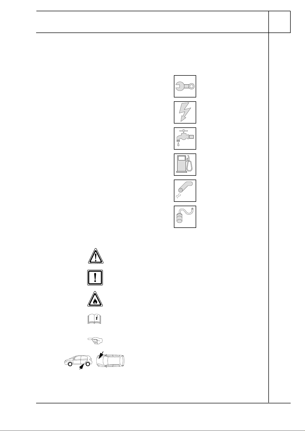
Explanatory Notes on Document
T o provide you with a quick overview of the individual working steps, you will find an identification mark
on the outside top right corner of the page in question.
Mechanical system
Electrical system
Water
Fuel
Exhaust gas
Combustion air
Special features are highlighted using the following symbols:
Specific risk of injury or fatal accidents.
Specific risk of damage to components.
Specific risk of fire or explosion.
Reference to general installation instructions of
Webasto components or to the manufacturer' s vehiclespecific documents.
Reference to a special technical feature.
The arrow in the vehicle icon indicates the position on
the vehicle and the
All dimensions are in mm!
Tightening torque of hose clamps = 2.0 + 0.5 Nm!
Tightening torque of Ejot screws, Ejot studs = 10 Nm!
1312760A_EN
viewing angle.
4
VW Golf V, Golf Plus, Touran
Preliminary Work
WARNING!
- Open the fuel tank cap, ventilate the tank.
- Close the tank cap again.
- Depressurize the cooling system.
- Copy the factory number from the original type label to the duplicate type label.
- Remove years that do not apply from the duplicate label.
- Attach the duplicate label (type label) in the appropriate place.
- Disconnect the battery "earth" or "ground" connection.
- Remove the battery
- Remove the battery carrier.
- Remove the engine cover
- Remove the left front wheel
- Remove the front section of the left front wheel well trim
- Remove the left-hand front fog light or, on vehicles without front fog lights, the left-hand cover
- Remove the underride protection
- Remove the right-hand underbody trim
- Golf only: Remove the rear bench seat
- Golf Plus only: Remove the right rear seat
- Open the right-hand fuel sender service lid.
- Remove the footwell trim on the driver's side
- Remove the lower instrument panel trim on the driver's side
- Only vehicles with Climatronic: Remove the footwell trim on the front passenger side
Remove page 35 "Operating Instructions for End Customer" and add to the vehicle operating
instructions.
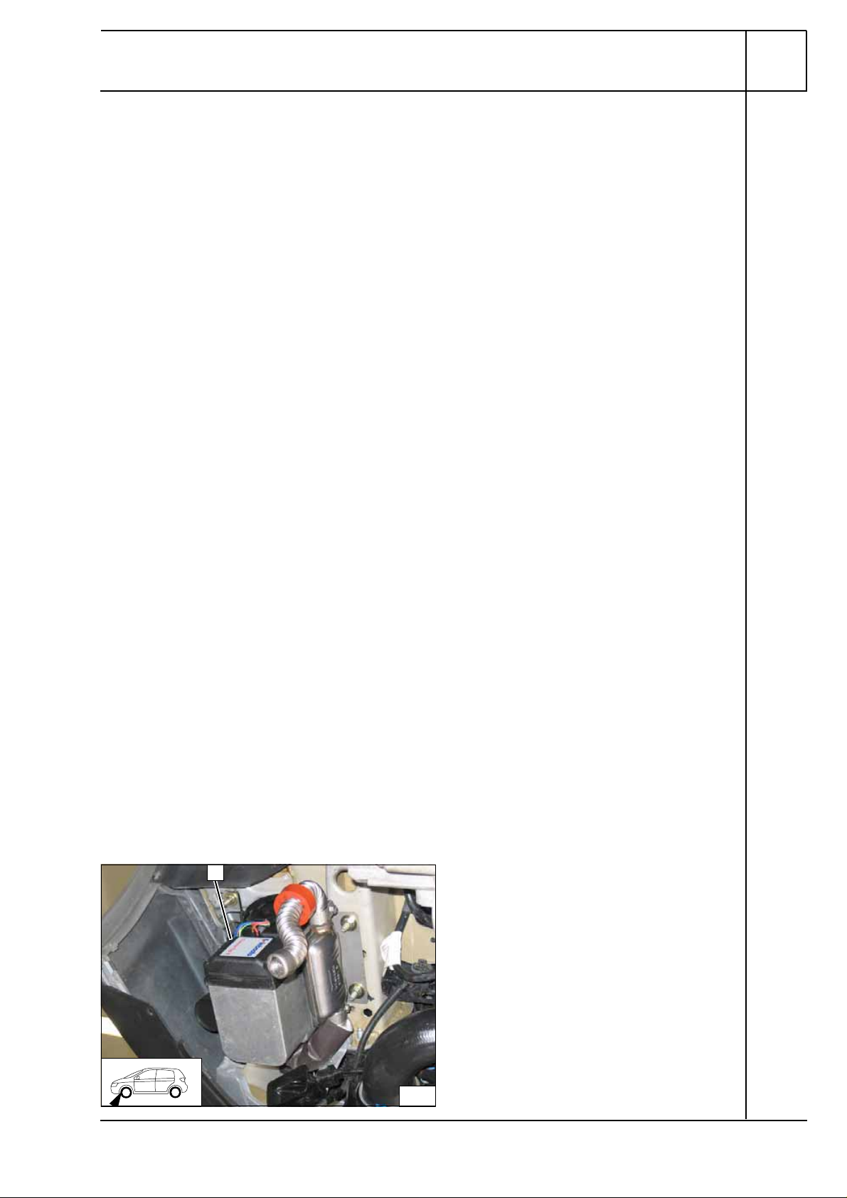
1
Heater unit installation location
1 Heater unit
1312760A_EN
Installation
location
1
5
VW Golf V, Golf Plus, Touran
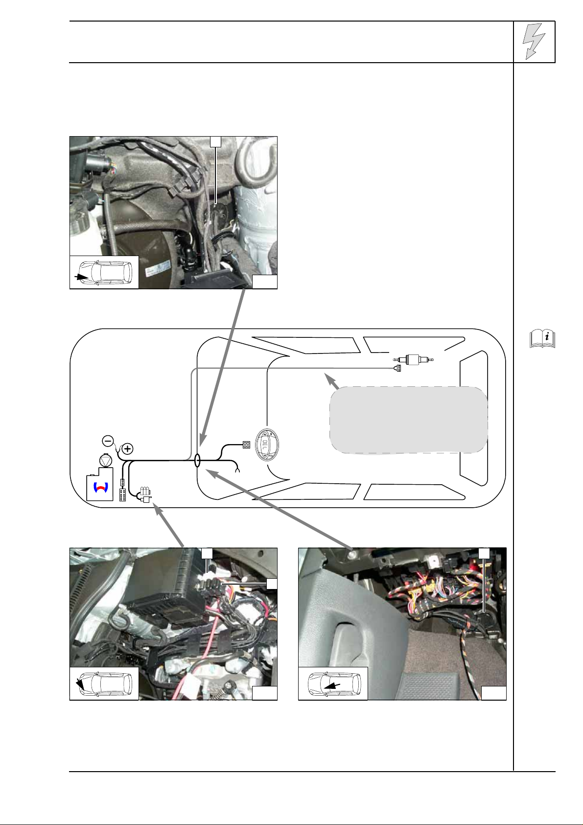
Electrical system
Wiring harness pass through
1 Original vehicle wiring harness pass through
1
2
Do not install the metering pump
cable harness until later together
with fuel pipe along the original
vehicle fuel lines on the
underbody
1
2
1
Wiring
harness
installation
diagram
3
Fuse holder, relay K3
Description of installation for K3 relay 1 and fuse
carrier 2 on Page 7
1312760A_EN
4
Wiring harness pass through
1 Original vehicle wiring harness pass through
6
VW Golf V, Golf Plus, Touran
40
1
2
99
20
3
3
11
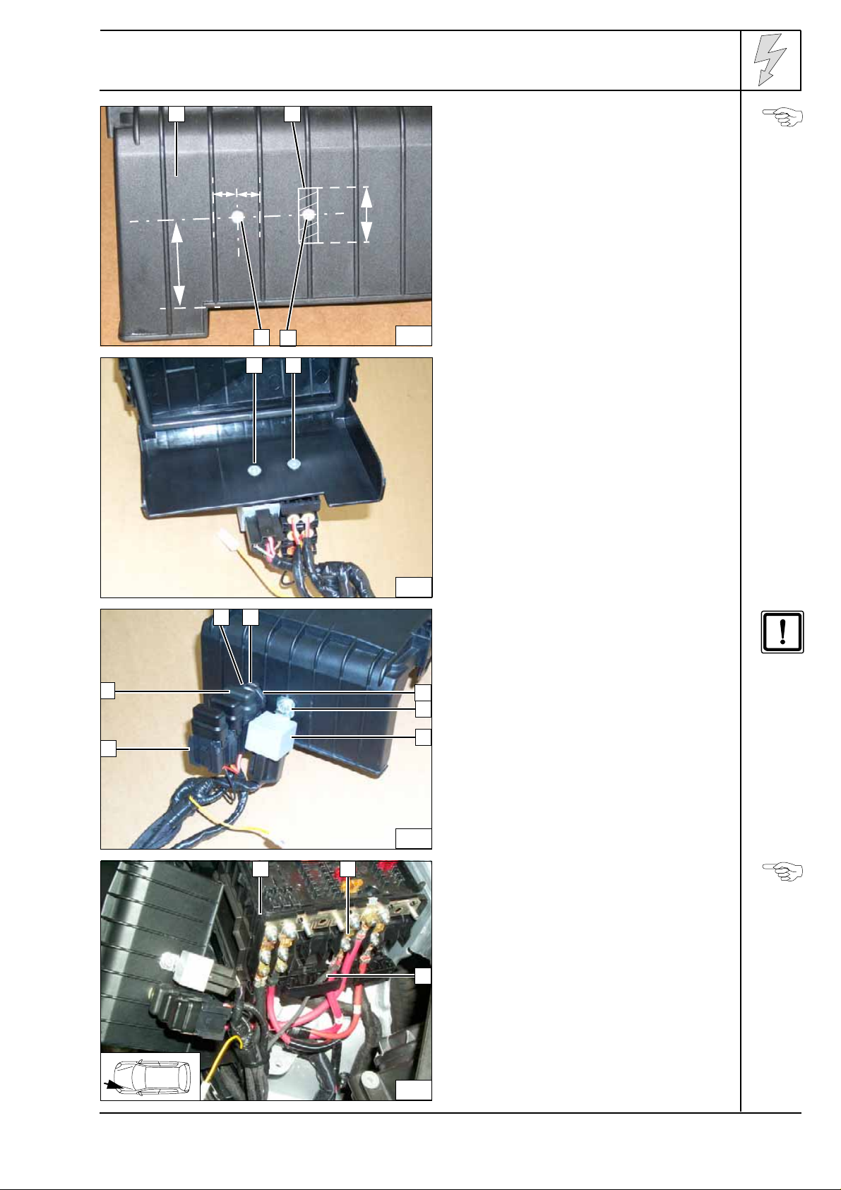
Fuse holder and relay K3
Countersink holes 3 from behind for M5
countersunk head screws.
1 Cover of fuse/relay carrier in engine
compartment
2 Cut away bar in shaded area
3 5.0 mm dia. hole [2x]
5
1 M5x12 countersunk head screw [2x]
Holes in
cover
Installing
fuse holder
and K3
relay
6
2
1
7
6
21
On vehicles with Climatronic, replace 25 A
fuse F3 7 with 3 A fuse provided.
1 M5 flanged nut
2 Large diameter washer (between cover
3
4
5
7
3
and retaining plate)
3 Retaining plate
4 M5 flanged nut
5 Relay K3
6 Fuse holder
Route brown (br) ground wire to original
vehicle ground support point below headlight
and connect.
1 Fuse/relay carrier
2 Original main vehicle fuse
3 Red (rt) positive wire
Installing
fuse holder
and K3
relay
Connecting
positive
and
ground
wire
1312760A_EN
8
7
VW Golf V, Golf Plus, Touran
2
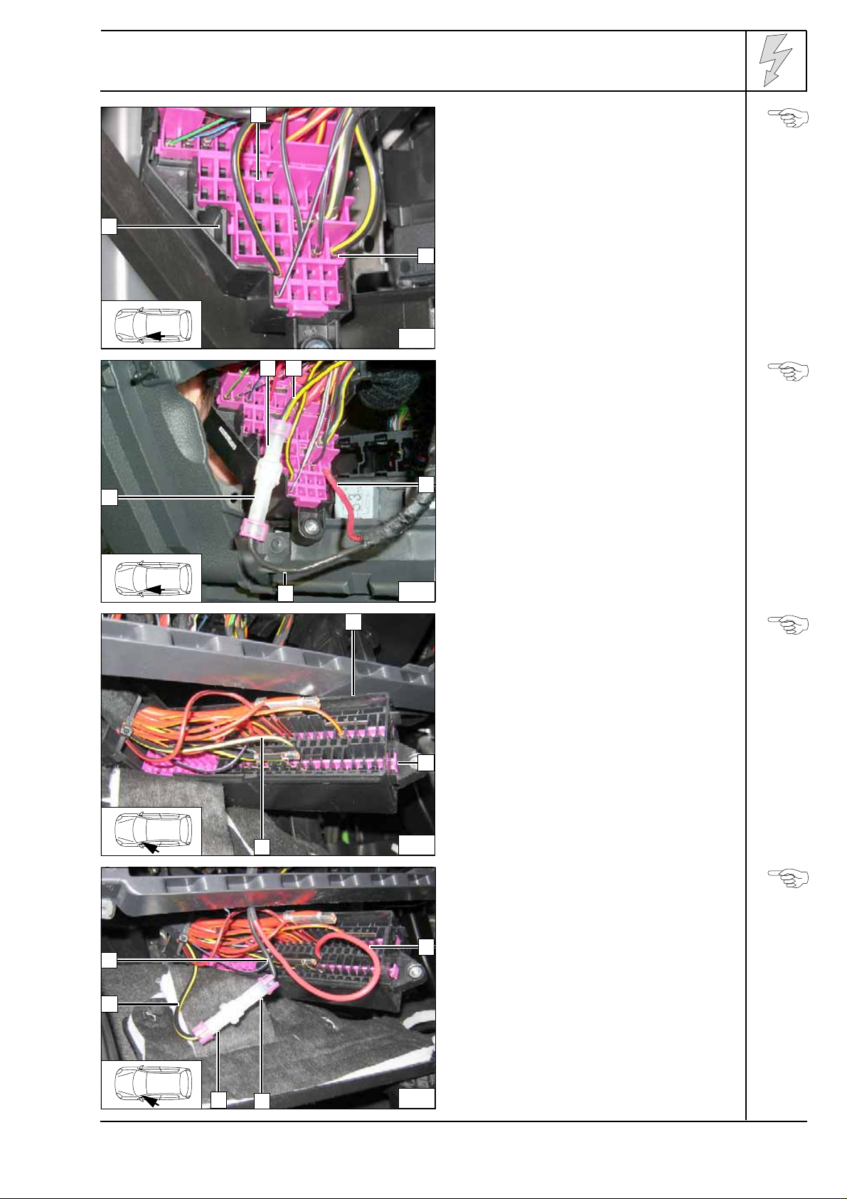
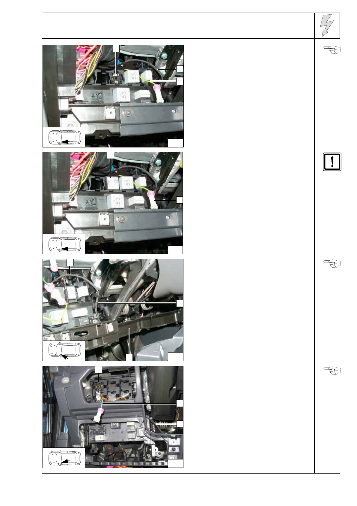
Climatic fan controller
Golf V
Detach original vehicle fuse carrier 1
(instrument panel at upper left) and unlock
contact lock 2.
1
2
1
5
Uncrimp 4² black/yellow (sw/ge) wire 3 on
fuse output SC40
3
9
Produce connections as shown in wiring
diagram.
1 AMP housing
3 Red (rt) wire from K3/87a with crimped-on
standard power timer engaged in fuse
output SC40
2 Black/yellow (sw /ge) wire with original
3
standard power timer
4 Black (sw) wire K3/30 with crimped-on tab
connector
5 AMP housing
Uncrimping
wire
Connecting
wires
4
1
3
5
4
10
11
Lock contact lock again.
Golf Plus and Touran
Fuse socket dependent on vehicle equipm ent
SC33 or SC 35; wire color black (sw) or
black/yellow (sw/ge)
Detach original vehicle fuse carrier 1
(instrument panel at lower left) and unlock
contact lock 2.
Uncrimp 4² black (sw) or black/yellow ( sw/ge)
2
wire 3 on fuse output SC33 or SC35
Produce connections as shown in wiring
diagram.
1 Red (rt) wire from K3/87a with crimped-on
1
standard power timer engaged in fuse
output SC33 or SC35
2 AMP housing
3 AMP housing
4 Black (sw) or black/yellow (sw/ge) wire
11/3 with original standard power timer
5 Black (sw) wire K3/30 with crimped-on tab
connector
Uncrimping
wire
Connecting
wires
1312760A_EN
3
2
12
Lock contact lock again.
8
VW Golf V, Golf Plus, Touran
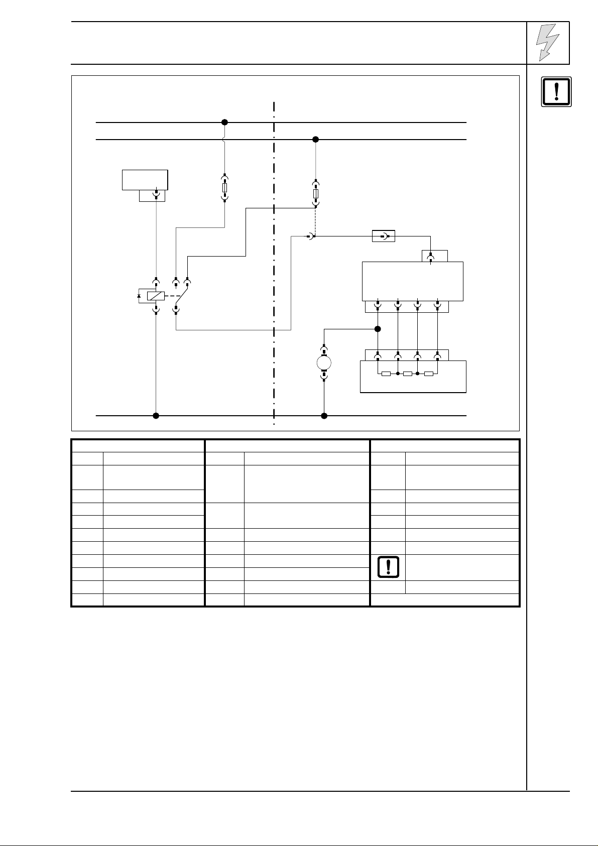
HG
4
X1
86
85 30
Webasto
87a87
K3
VW
30
15
F3
4²
rt
F1
4²
sw
(sw/ge)
T10k
5
T5
KB
31 24
T5
sw
4²
+
M
GM
-
34 21
T4r
WG
Wiring
diagram
Webasto components Vehicle components Colors and symbols
HG Heater unit TT-C/E GM Fan motor rt red
X1 6-pin heater unit
F1 Fuse SC33 or SC35 with 40 Aws white
connector
F3 Fuse, 25 A sw black
K3 Fan relay KB Air-conditioning control unit
or heater switch E16
br brown
gn green
WG Resistor group N24 bl blue
T10k Connector ge yellow
Insulate wire ends and
tie back
X Cutting point
Wiring colors may vary.
31
Legend
1312760A_EN
9
VW Golf V, Golf Plus, Touran
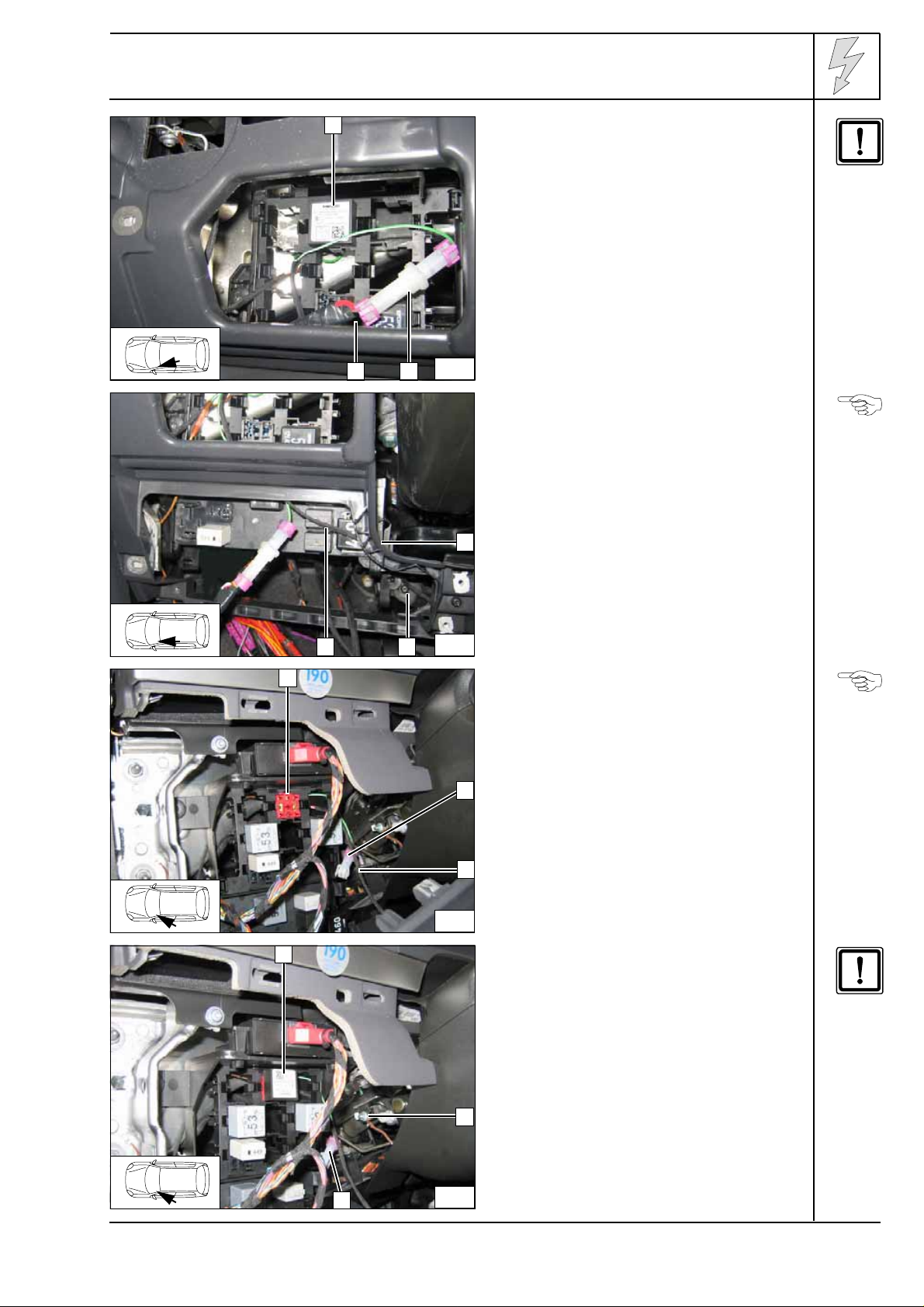
1
Climatronic fan controller
Golf V
2
Produce connections as shown in wiring
3
diagram.
Position of free sockets dependent on vehicle
equipment.
1 IPCU socket
2 Red (rt) and black/white (sw/ws) wires from
IPCU
3 Green/white (gn/ws) wire to IPCU/86 with
13
1
2
AMP connector
Brown (br) wire from IPCU/85 to original
vehicle ground point.
Insulate and tie back red (rt) wire from
K3/87a.
Connect black (sw) wire from K3/30 to
green/white (gn/ws) wire (AMP connector)
1 IPCU
Installing
wiring
harness of
Climatronic
2.
Connecting
wires
14
1
2
1
15
Route wiring harness IPCU 1 along cross
member
1
2 to center console
Golf Plus
Produce connections as shown in wiring
diagram.
Position of free sockets dependent on vehicle
equipment.
2
1 IPCU socket
2 Green/white (gn/ws) wire to IPCU/86 with
3
AMP connector
3 Red (rt) and black/white (sw/ws) wires from
IPCU
Routing
wiring
harness
from IPCU
Installing
wiring
harness of
Climatronic
1312760A_EN
16
10
VW Golf V, Golf Plus, Touran
1
17
23
Brown (br) wire from IPCU/85 to original
vehicle ground point.
Insulate and tie back red (rt) wire from
K3/87a.
Connect black (sw) wire from K3/30
green/white (gn/ws) wire (AMP connector)
1 IPCU
Route wiring harness IPCU 2 along cross
member
1
1 to center console.
3 to
2.
Connecting
wires
Routing
wiring
harness
from IPCU
18
2
1
1
2
Touran
Produce connections as shown in wiring
diagram.
Position of free sockets dependent on vehicle
19
equipment.
2
1 IPCU socket
2 Green/white (gn/ws) wire to IPCU/86 with
AMP connector
3 Red (rt) and black/white (sw/ws) wires from
3
IPCU
Fasten brown (br) wire from IPCU/85 to
original vehicle ground point
Insulate and tie back red (rt) wire from
K3/87a.
Connect black (sw) wire from K3/30 to
green/white (gn/ws) wire (AMP connector)
1 IPCU
2.
Installing
wiring
harness of
Climatronic
3.
Connecting
wires
1312760A_EN
2
3
20
11

VW Golf V, Golf Plus, Touran
Route wiring harness from IPCU 1 to fan unit.
Routing
wiring
harness
from IPCU
1
21
1 2
1
3 42
Golf V, Golf Plus, Touran
1 Wiring harness with red (rt) wire from
IPCU/E and black/white (sw/ws) wire from
IPCU/A
2 Fan unit
22
Position of connector T6t is dependent on
vehicle. If necessary, disconnect fan unit in
accordance with manufacturer's instructions.
Produce connections as shown in wiring
diagram.
1 Wiring harness from IPCU
2 Black/white (sw/ws) wire from IPCU/A
3 Red (rt) wire from IPCU/E
5
4 Black/white (sw/ws) wire from Climatronic
control unit
5 Connector T6t
6 Black/white (sw/ws) wire to connector
T6t/2
6
23
Routing
wiring
harness
from IPCU
Connecting
wires
6
1312760A_EN
1 2
5
24
Picture shows version without having to
disconnect fan unit.
1 Black/white (sw/ws) wire from IPCU/A
2 Black/white (sw/ws) wire to connector
3
4
T6t/2
3 Connector T6t
4 Black/white (sw/ws) wire from Climatronic
control unit
5 Red (rt) wire from IPCU/E
6 Wiring harness from IPCU
Connecting
wires
12

VW Golf V, Golf Plus, Touran
1
Kabelbaum
Hg
HG
4
X1
rt
86
85 30
87a87
K3
2
If previously removed, reinstall fan unit.
Fasten wiring harness on original vehicle
wires with cable ties.
1 Wiring harness from IPCU
2 Fan unit
25
Kabelbaum
Climatronic
F3
! 0,75²
IPCU
86 85
gn/
ws
E
rt
A
sw/ws
0,75²
0,75²
0,75²
KB
15 16
sw/
bl/
ws
ws
sw/
ws
VW
T16f
ge
rt/ws
Installing
fan unit
30
Wiring
15
diagram
F1
rt/
T10k
31 42
sw
M
T6t
GE
br
br
31
Webasto components Vehicle components Colors and symbols
HG Heater unit TT-C/E F1 Fuse SC22 or SC56 with 40 A rt red
X1
6-pin heater unit connector
K3 Fan relay KB Climatronic control unit - J255 sw black
F3 Fuse (25 A replaced
with 3 A!)
IPCU Pulse width modulator ge yellow
T10k Plug connections br brown
ge Fan control unit - J126 and fan
motor - V2
IPCU adjustment values bl blue
Voltage: 8 V
Frequency: 400 Hz Insulate wire end
Duty cycle: 30 %
Function: High-side
1312760A_EN
ws white
gn green
and tie back
X Cutting point
Legend
13

VW Golf V, Golf Plus, Touran
1
Digital timer, summer/winter switch option
Golf V
Do not press on display!
1 Digital timer
2
2 Summer/winter switch
26
1
Golf Plus
Do not press on display!
1 Summer/winter switch
2 Digital timer
2
Digital
timer
Digital
timer
1 2
1
27
Touran
1 Digital timer
2 Summer/winter switch
Summer/
winter
switch
option
28
2
Remote option (Telestart)
Golf V
If M6 screw 2 is not present, then use suitable
M6 screw with spring lockwasher.
Drill out upper hole of bracket to 6.5 mm dia.
3
1 Receiver
2 M6 bolt
3 Bracket
Installing
receiver
1312760A_EN
29
14

VW Golf V, Golf Plus, Touran
1
30
1
1 Antenna
Golf Plus
Bend down lower tab of bracket by 90° and
drill out hole to 6.5 mm dia. as shown.
1 Receiver
2 Bracket
3 M6 bolt, large diameter washer (between
2
bracket instrument carrier), large diameter
washer (from outside), flanged nut
4 Instrument carrier, existing hole
3
Installing
antenna
Installing
receiver
4
31
1
1
32
1
Antenna
Touran
1 Instrument carrier
2 Existing hole, M6x20 bolt, large diameter
washer, flanged nut
3 Bracket, drill out hole to 6.5 mm dia.
4 Receiver
Installing
antenna
Installing
receiver
1312760A_EN
234
33
15

VW Golf V, Golf Plus, Touran
1
34
1 Antenna
Installing
antenna
1312760A_EN
16

VW Golf V, Golf Plus, Touran
1
a
X
1
Premounting heater unit
1 Combustion air pipe
a = 250
Discard section
Ejot stud, tightening torque 10 Nm.
1 Ejot stud
X
Cutting
combustion air
pipe to
length
Premounting
heater unit
152 3
2
2
1
3 3
35
4
36
Insert one washer each between heater unit
and bracket at positions
1
M6x30 spacer nut
2 Washer, Ejot screw [2x]
3 Hose clamp
4 Prepared combustion air pipe (slotted side
on heater unit)
5 Bracket
Hose section
1
2 Strut
3 Ejot screw [2x]
4 Combustion-air intake muffler
5 Retaining clip in hole of heater unit
6 Combustion air pipe
7 10 mm dia. hose clamp [2x]
8 Mecanyl line
4
2
Premounting
heater unit
Premounting
heater unit
1312760A_EN
5
6778
37
17

VW Golf V, Golf Plus, Touran
1 2
a b
X
21
2
1 Exhaust pipe
a = 190
2 Exhaust end section
b = 240
Discard section
M6x16 bolt, spring lockwasher
1
2 Hose clamp [2x]
3 Red (rt) rubber isolator, without groove
4 Exhaust pipe with insulation
5 Muffler
X
Cutting
exhaust
pipe to
length
Premounting
exhaust
system
5
1
4
1
3
38
Hose clamp
1
2 Red (rt) rubber isolator, without groove
3 Exhaust end section
2
3
39
12
Preparing installation location
Secure large diameter washer against falling
with putty etc.
1 Large diameter washer on original vehicle
stud bolt [3x]
2 Edge protection section
1
Premounting
exhaust
system
Preparing
installation
location
1312760A_EN
40
18

VW Golf V, Golf Plus, Touran
1
41
3 1
Installing heater unit
1 Large diameter washer, flanged nut M8
1
1
1
2
[3x]
Ensure freedom of movement of exhaust
system relative to original vehicle component
and lines.
1 Original vehicle wiring harnesses (secured
with cable ties)
2 Horn
3 Exhaust pipe
Installing
heater unit
Aligning
exhaust
system
42
Ensure freedom of movement of exhaust
system relative to original vehicle component
and lines.
1
Position rubber isolator
(Picture shows Golf Plus with headlight
washer system)
1 Headlight washer system (Golf Plus)
4
1
3
43
2
3 Horn
4 Horn bracket
3
Watch routing of wiring harness. Dang er of
rubbing!
1 Wiring harness of heater unit
2 Clip cab le tie in pr e-perforated hole of
heater unit cover
3 Cable tie
2
2 as shown.
Aligning
exhaust
system
Mounting
and
routing
wiring
harness
1312760A_EN
44
19

VW Golf V, Golf Plus, Touran
Watch routing of wiring harness. Dang er of
1
rubbing!
Route excess lengths from wiring harness
in cable duct
cable ties.
1 Wiring harness from heater unit
2 Cable duct
22
45
2 below battery and secure with
1
Routing
wiring
harness
1312760A_EN
20

VW Golf V, Golf Plus, Touran
Fuel Connection
CAUTION!
Open the vehicle's fuel tank cap, ventilate the tank and then re-close the tank lock.
Catch any fuel running off with an appropriate cont ainer.
Install fuel line and metering-pump wiring harness so that they are protected against stone impact.
Unless specified otherwise, always fasten using cable ties.
Mount the fuel line and wiring harness with rub protection on sharp edges.
WARNING!
The fuel line and wiring harness are routed to the metering pump in as shown in the wir i ng harness
routing diagram.
1 1 1
1 2
46
47
1 Mecanyl line
Coolant reservoir cap detached
1
2 Existing pass through
3 Mecanyl line and wiring harness of
metering pump
3
Routing
mecanyl
line to
firewall
Routing
mecanyl
line and
wiring
harness of
metering
pump into
coolant
reservoir
1 1
1312760A_EN
48
Fasten mecanyl line and wiring harness of
metering pump
original vehicle lines with cable tie.
Pay particular attention to freedom of
movement of wiper linkage.
1 in coolant reservoir on
Routing
mecanyl
line and
wiring
harness of
metering
pump to
right
21

VW Golf V, Golf Plus, Touran
1
1
2
2
49
1 Metering pump wiring harness
2 Existing pass through
3 Mecanyl line
3
Route mecanyl line and wiring harness of
metering pump along original vehicle fuel
2 to fuel tank.
lines
1 Line duct
Routing
mecanyl
line and
wiring
harness of
metering
pump
Routing
mecanyl
line and
wiring
harness of
metering
pump
50
1
Silentblock, large diameter washer, M6
flanged nut
2 Remove sealing plug
Installing
1
2
2
1 364
8
6
51
Metering pump wiring harness
1
2 Connector housing, single-wire seals,
plug-in contacts
3 Secure rubber-coated p-clamp on silent
block with flanged nut
4 Metering pump
5 Plug remounted
6 10 mm dia. hose clamp [2x]
7 Hose section
8 Mecanyl line
noise
isolation
mount
Mounting
metering
pump and
connecting
pressure
side
1312760A_EN
7
5
52
22

VW Golf V, Golf Plus, Touran
.
1 2
0
1
7.5 mm dia.
235
1
7.5 mm dia.
4.5 mm dia
53
3
2
4.5 mm dia.
1 Standpipe
2 Molded hose
Caillau clamp 2 in center between beads on
end of standpipe.
1 Standpipe
2 10 mm dia. Caillau clamp
3 Molded hose
Cutting
standpipe
and
molded
hose to
length
Premounting
standpipe
and
molded
hose
54
1
1
2
55
Cut 3 mm off blind plug.
1 Tip cut off blind plug
2 Fuel sender
Should the standpipe be slightly curved on
delivery, then it must be aligned so that the
end points toward the rear right.
Otherwise there is a danger of the fuel gauge
being impaired.
1 13.5 mm dia. Caillau clamp
2 Preassembled molded hose with
2
3
standpipe
3 10 mm dia. Caillau clamp
4 Remaining piece of mecanyl line
Cutting off
blind plug
Connection to
fuel-tank
sending
unit
1312760A_EN
4
56
23

VW Golf V, Golf Plus, Touran
1
3
3
57
1 Hose section
2 Mecanyl line from fuel-tank sending unit
3 10 mm dia. hose clamp [2x]
2
Connecting
intake side
of metering
pump
1312760A_EN
24

VW Golf V, Golf Plus, Touran
Coolant on 1.4 TSI
WARNING!
Any coolant running off should be collected using an appropr i ate container. Install hoses so that they
are kink-free. Unless specified otherwise, always fasten using cable ties. Position clamps so that no
other hose can be damaged! When installing the coolant hose, the heater unit must be filled with
coolant.
The connection should be "inline" based on the following diagram:
Coolant
routing
diagram
1
C
A
B
All spring clips without a specific designation = 27 mm dia. 1 = Original vehicle spring clip .
All hose clamps = 20-27 mm dia.!
All connecting pipes = 20x20 dia..
1312760A_EN
25

VW Golf V, Golf Plus, Touran
a = 600
b = 50
c = 770
CA
1 1
C
X
B
Discard section
X
Push braided protection hoses onto hose A
C, cut to length and shrink.
and
1 Heat shrink plastic tubing [4x]
1
Cutting
coolant
hoses to
length
Premounting
coolant
hoses
B
1
A
11
58
1
Cable ties with clip [2x]
2 Bracket for coolant hoses
Preparing
bracket for
coolant
hoses
2
1
2
59
Loosen original vehicle bolt 2 and position
bracket for coolant hoses
carrier
1 and body 3.
5 between battery
4 M6x20 bolt, original vehicle hole, flanged
nut
Installing
bracket for
coolant
5
hoses
1312760A_EN
4 3
26

VW Golf V, Golf Plus, Touran
1
2
1
60
1 Pull hose off heat exchanger inlet
2 Original spring clip will be reused
Cutting
point
Ensure sufficient distance to neighboring
components.
1 Hose on heat exchanger inlet
Connecting
heat
exchanger
inlet
C
61
Routing in
engine
compartment
C
B
62
C
Connection to
heater unit
1312760A_EN
63
27

VW Golf V, Golf Plus, Touran
A
64
3
2
1
A
4
Install hose A with 180° elbow on connection
piece of engine outlet.
C
Drill out perforated bracket 2 to 8.5 mm dia. at
position 3.
1 M6x20 bolt, flanged nut
3 Original vehicle bolt
4 29 mm dia. rubber-coated p-clamp [2x]
Connecting
engine
outlet
Fastening
hoses
C
4
A
C
A
1 1
65
66
Ensure sufficient distance to neighboring
components.
C
Fix hose A and C in place with clip-type cable
1 [2x].
ties
Aligning
hoses
Fastening
hoses
1312760A_EN
67
28

VW Golf V, Golf Plus, Touran
Coolant on 1.6 FSI
WARNING!
Any coolant running off should be collected using an appropr i ate container. Install hoses so that they
are kink-free. Unless specified otherwise, always fasten using cable ties. Position clamps so that no
other hose can be damaged! When installing the coolant hose, the heater unit must be filled with
coolant.
The connection should be "inline" based on the following diagram:
Coolant
routing
diagram
1
2
B
A
All spring clips without a specific designation = 27 mm dia. 1 = Original vehicle spring clip .
All hose clamps = 20-27 mm dia.! Connecting pipe = 20x20 dia.
2 = Black (sw) rubber isolator .
1312760A_EN
29

VW Golf V, Golf Plus, Touran
a = 1000
b = 1050
A
1 1
B
3
Discard section
B
X
Cutting
coolant
hoses to
length
Push braided protection hoses onto hose A
B, cut to length and shrink.
and
1 Heat shrink plastic tubing [4x]
Premounting
coolant
hoses
1
2
A
2
1
68
1
Pull off hose on engine outlet to heat
exchanger inlet
exchanger inlet
3 on connection piece of heat
2. Spring clip 1 will be reused.
Install battery carrier.
Cutting
point
3
69
Connection piece of heat exchanger inlet
1
B
1
Connecting
heat
exchanger
inlet
1312760A_EN
70
30

VW Golf V, Golf Plus, Touran
B
Routing in
engine
compartment
71
B
C
Connection to
heater unit
72
Routing in
engine
compartment
A
B
1
A
1312760A_EN
73
74
Engine-outlet hose section
1
2 Alig n ru bb er profile
2
Connecting
engine
outlet
31

VW Golf V, Golf Plus, Touran
1
2
2
A
B
75
1 M6x20 screw, spring lockwasher on
existing thread
2 29 mm dia. rubber-coated p-clamp [2x]
Fastening
hoses
1312760A_EN
32

VW Golf V, Golf Plus, Touran
1
76
Exhaust gas
Align exhaust end section and rubber isolator
as shown.
Ensure sufficient spacing of exhaust end
1
section to transmission and to wheel well
trim.
(Picture shows vehicle with direct shift
transmission)
1 Wheel well trim
Underride protection
1
2 42 mm dia. hole
Installing
wheel well
trim
Hole in
underride
protection
2
77
1
1 2
2
78
Picture shows Golf V!
Align exhaust end section
rubber isolator
3 Un de r rid e protection
3
Cut off section
1
2 Front fog light trim piece (depending on
equipment)
2.
3 flush on red
Mounting
rubber
isolator
1312760A_EN
Cutting
front fog
light trim
piece to
size
79
33

VW Golf V, Golf Plus, Touran
Final Work
WARNING!
Reassemble the disassembled components in reverse order.
Check all hoses, spring and Caillau clamps, as well as all electrical connections for firm seating.
Secure all loose cables using cable ties.
Spray heater unit components with anti-corrosion wax (Tectyl 100K, Order No. 111 329).
- Connect the battery
- Fill and bleed the coolant circuit according to the vehicle manufacturer’s specifications.
- Set the digital timer.
- Adjust vehicle heater in accordance with "Operating Instructions for End Customer"
- Check the proper operation of the additional heater, see the operating instructions/installation
instructions.
- File included vehicle-specific "Operating Instructions for End Customer“ in vehicle logbook
- Attach the "Switch off additional heater before refueling" sticker to the left-hand B-pillar.
Adjust the sensitivity of the passenger compartment monitoring
WARNING!
This can only be carried out at an authorized workshop! Observe the applicable repair manual of the
respective vehicle.
- Connect the VAS tester.
- Open Item 46 (Central Module of Comfort System)
- Go to Item 10 (Adjustment)
- Follow the request for the code entry and enter the code 15
- Reduce the sensitivity of the passenger compartment monitoring to 50 %
- Save this setting
- The adjustment of the sensitivity of the passenger compartment monitoring is completed.
1312760A_EN
Feel the drive
Webasto AG
Postfach 80 - 82132 Stockdorf
Hotline 01805 / 932278 - Hotfax 0395 / 5592-353
http://www.webasto.de
Printed in Germany 09/2007 Printing:
Steffen

VW Golf V, Golf Plus, Touran
Operating Instructions for End Customer
Please remove page and add to the vehicle operating instructions.
Note:
We recommend matching the heating time to the driving time.
Heating time = driving time
Example:
For a driving time of approx. 20 min. (in one direction), we recomme nd not exceeding a switch- on time
of 20 min.
If the summer/winter switch option has been installed, this must be switched in accordance with the
time of year. The heater unit will then only switch on the vehicle fan to ventilate the vehicle interior in
the position Winter heat and in the position Summer .
Before parking the vehicle, make the following settings:
1 2
3
1 2 1
80
1 Set temperature to "max."
2 Air outlet to winds hield
3 Set fan to level "1", or possibly "2"
Set temperature to "HI“ [2x]
1
2 Air outlet fac es upward
Climatic
Climatronic
1312760A_EN
81
35
 Loading...