

Page 1
Service Training
Self-study programme 560
The Caddy 2016
Commercial
Vehicles
Page 2
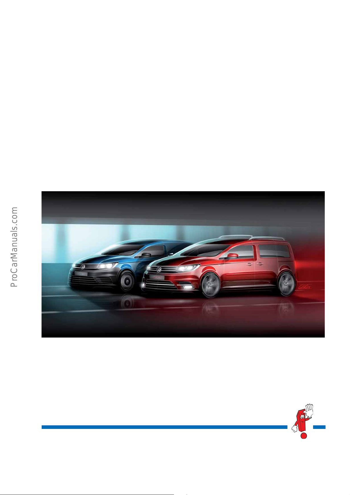
Worldwide, about 1.5 million Caddy vehicles of the previous generations have been sold over an 11 year period.
S560_002
We intend to continue this success story with the new Caddy 2016. This is because the award winning urban
livery van has been perfected and sharpened up in all areas. The same goes for its privately used brother. With
de
a total of 4 equipment variants, the compact van will appeal to a
wide range of customers. And not forgetting the
leisure automobile, the Caddy Beach. It goes without saying that the new generation is once again available with
wheel drive (4MOTION).
4-
Volkswagen Commercial Vehicles is responding to individu
powertrains. In total, there are 4 TDI engines, 3 TSI engines and one TGI engine, optionally available with 5 or
6-speed manual gearboxes, 6 or 7-speed dual clutch gearbox. In addition, the four-wheel drive can be combined
ith 2 engines and gearboxes.
w
al requirements with a diverse range of engines and
Self-Study Programme presents the
design and function of new
developments!
The content will not be updated.
Current testing, setting and repair instructions
n be found in the service literature provided.
ca
Important
Note
2
Page 3

At a glance
Introduction . . . . . . . . . . . . . . . . . . . . . . . . . . . . . . . . . . . . . . . . . . . . . . . . . . . . . 4
Body . . . . . . . . . . . . . . . . . . . . . . . . . . . . . . . . . . . . . . . . . . . . . . . . . . . . . . . . . . 8
Power units . . . . . . . . . . . . . . . . . . . . . . . . . . . . . . . . . . . . . . . . . . . . . . . . . . . . 14
Power transmission . . . . . . . . . . . . . . . . . . . . . . . . . . . . . . . . . . . . . . . . . . . . . 30
Running gear . . . . . . . . . . . . . . . . . . . . . . . . . . . . . . . . . . . . . . . . . . . . . . . . . . 32
Heating and air conditioning . . . . . . . . . . . . . . . . . . . . . . . . . . . . . . . . . . . . . 43
Electrical system . . . . . . . . . . . . . . . . . . . . . . . . . . . . . . . . . . . . . . . . . . . . . . . . 46
Radio, telephone and navigation . . . . . . . . . . . . . . . . . . . . . . . . . . . . . . . . . . 54
3
Page 4
S560_005
S560_004
Introduction
The product features of the Caddy 2016
The overview lists new and striking product characteristics of the Caddy 2016. Deviations are possible depending
on the country.
• Roof rails
• 360° parking system
• Heated windscreen
• Multicollision brake
• Petrol engines of the
EA211 series
• Front Assist with
Automatic Emergency Braking
• Diesel engines of the
EA288 series
• 4MOTION with dual clutch gearbox and
generation V 4WD coupling
• Cruise control system (CCS) including speed limiter
• New range of colours
4
Page 5
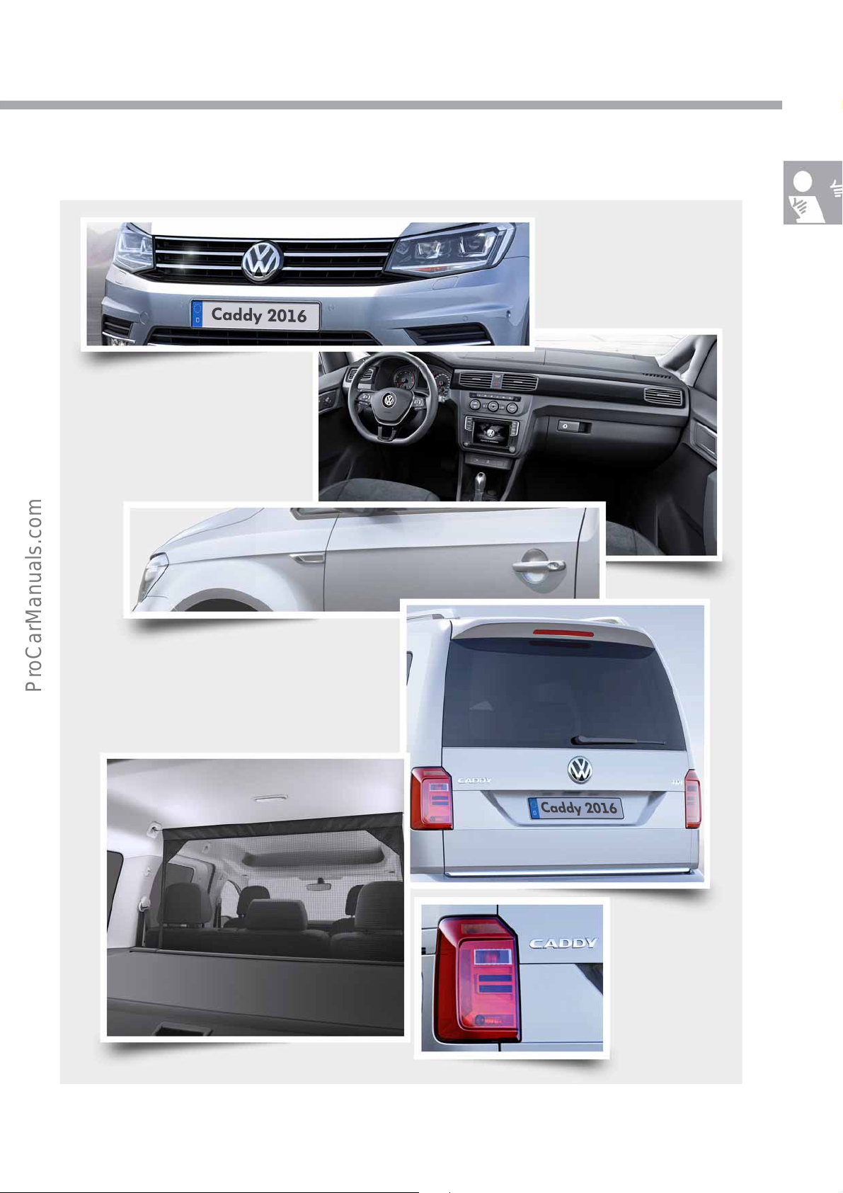
The recognition features of the Caddy 2016
S560_006
Newly designed headlights
and front bumper
Dash panel with numerous
storage possibilities
Striking side profile line with cut-in, rectangular
turn signal repeater
Tailgate with larger number plate
panel and continuous rear window
Moulded headliner and roll-up
tonneau cover
Newly designed tail
light clusters
5
Page 6
S560_007
879 8472682
4408
Introduction
S560_061
1536
1793
2065
166
S560_062
1534
1823
577
Technical data
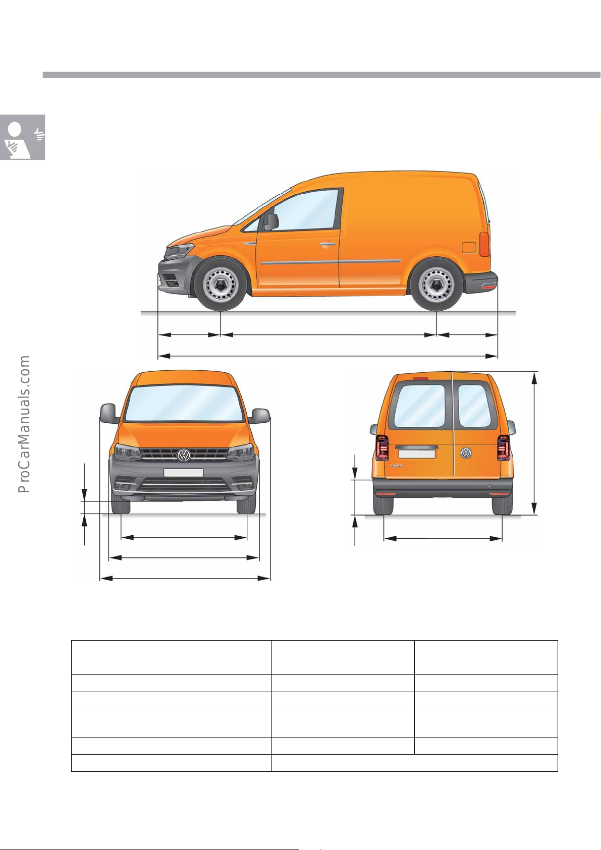
Caddy panel van
View and dimensions taking the example
of a panel van with front-wheel drive and
short wheelbase
Weights (examples)*
Unladen weight including driver* 1398 - 1603 kg 1537 - 1818 kg
Gross vehicle weight rating* 2045 - 2160 kg 2345 kg
Braked trailer load on 12% / 8% incline
6
Payload/load capacity 557 - 647 kg 527 - 808 kg
Roof load 100 kg for all Caddy versions
* Depending on engine and equipment
Caddy panel van
Short wheelbase
1300 - 1500 kg / 1500 kg
Caddy Comfortline
Long wheelbase (Maxi)
7-seater
1100 - 1500 kg /
1400 - 1500 kg
Page 7
S560_063
1537
1793
2065
158
S560_008
879 9933006
4878
S560_064
1544
1868
581
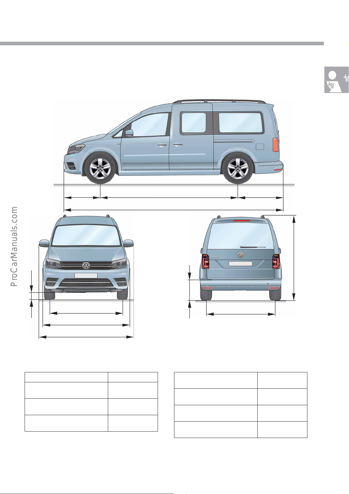
Caddy window van, Trendline, Comfortline, Comfortline Edition, Beach
View and dimensions taking the example
of a Caddy Comfortline with front-wheel
drive and long wheelbase (Maxi)
Additional dimensions
Turning circle, short wheelbase 11.1 m
Turning circle, long wheelbase
(Maxi)
Fuel tank volume front/4-wheel
drive
Vehicle length with tow hitch 4506 mm
12.2 m
55 l / 60 l
4976 mm (Maxi)
Loading volume taking example
of a Caddy Maxi Comfortline
With upright 3rd seat row to top
edge of backrest
Behind 2nd seat row in passenger
compartment with cover
With double-folded 2nd seat row
in the passenger compartment
Without seats in the passenger
compartment
530 l
1350 l
3700 l
3880 l
7
Page 8
Body
S560_112
S560_154
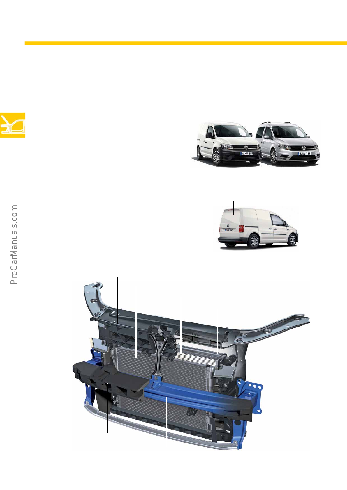
Tailgate with metal panel
S560_111
Cooler for power steering
Foam insert
Impact beam
Condenser
Water radiator for charge air cooling circuit
Assembly mount
The body
To a large extent, the body has been taken from the previous model. The front and rear ends are new – they have
been adapted to the current family face at Volkswagen and are the same for the can and commercial vehicles.
New features on the body:
•Engine lid
•Wing
• Radiator grille with Volkswagen badge
•Front bumper
•Rear bumper
•Tailgate
• Exterior mirror (car variant)
The newly designed tailgate has a continuous
window. The panel van also has the option of a
tailgate with a complete metal panel.
Front end
8
Page 9
S560_107
1
1
1
3
4
2
5
9
8
7
7
6
8
10
1
6
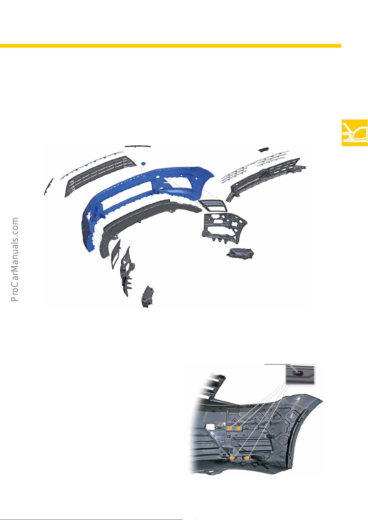
Bumper cover
S560_155
Bonded connection
The newly designed bumper cover is stabilised by 2 support inserts fitted at the sides. The support inserts
additionally serve as carriers for the fog lights. In bumpers in the painted version, the support inserts are
exclusively connected to the bumper cover using clip connections.
The illustration shows the painted version
Legend
Trim strip
1
Radiator grille centre
2
Cap for towing eye
3
Bumper cover
4
Spoiler
5
Bumper cover and radiator grille form one structural
unit in the non-painted, grained version. The support
inserts are connected to the bumper cover using clips
and 4 additional bonded connections. The bonded
connections provide spot connections for the
thermoplastic materials of the bumper cover and the
support insert. The air intake grilles with the openings
for the fog lights are covered by the support inserts.
To be able to remove the air intake grilles, it is first
necessary to remove the relevant support insert.
Air intake grille with opening for fog light
6
Trim for fog light
7
Fog light
8
Radiator grille
9
Lettering
10
9
Page 10
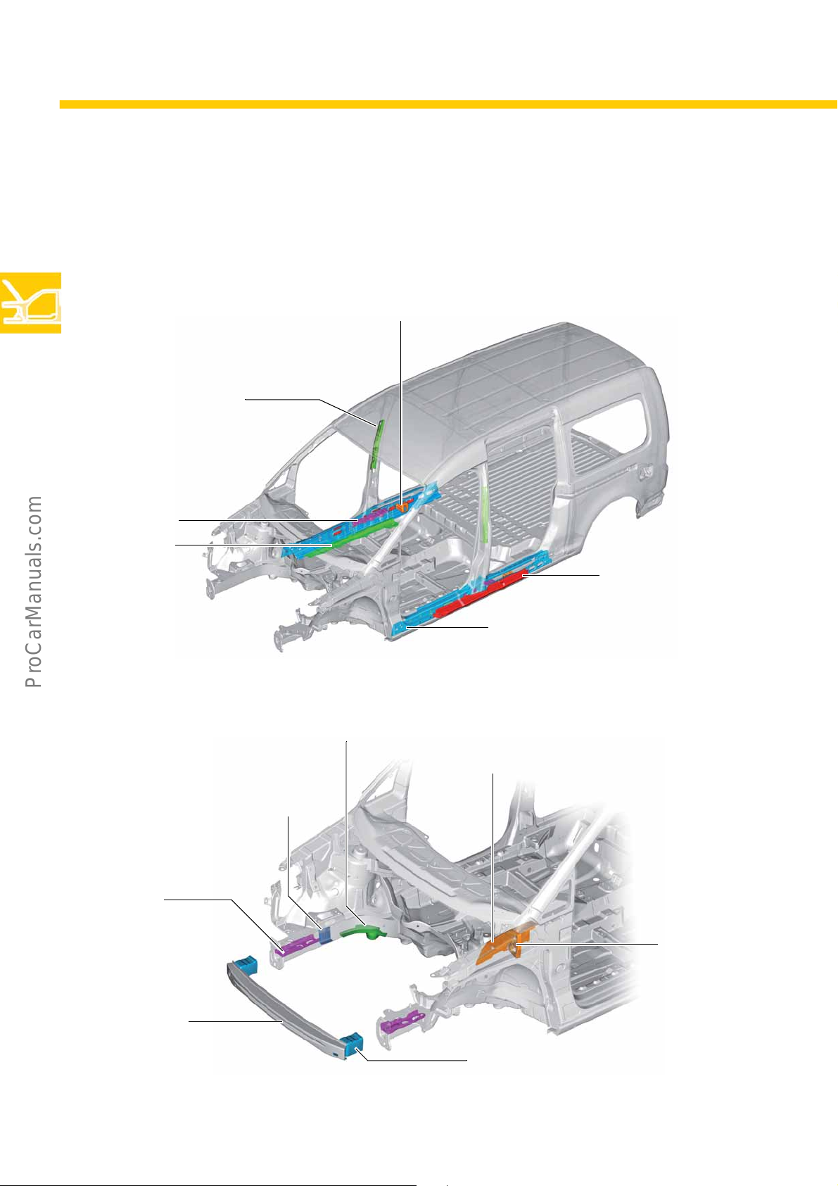
Body
S560_137
Sill panel reinforcement
(sill panel doubler)
Web plate of the sill panel
(optimised)
Web plate on sill panel
Insert for reinforcement
of the B-pillar
Web plate,
checker plate
Cover plate
floor
(on both sides)
S560_138
Reinforced mounting bracket
Web plate
Reinforcement side member
Reinforcement side member top
(in LHD vehicles installed on left and in RHD vehicles
installed on both sides)
Deformation element
(optimised)
Impact beam
Web plate
The body structure
To improve body stability in an accident, corresponding reinforcements have additionally been integrated into the
body structure.
Reinforcements for side-on collision
Reinforcements for front-end collision
10
Page 11
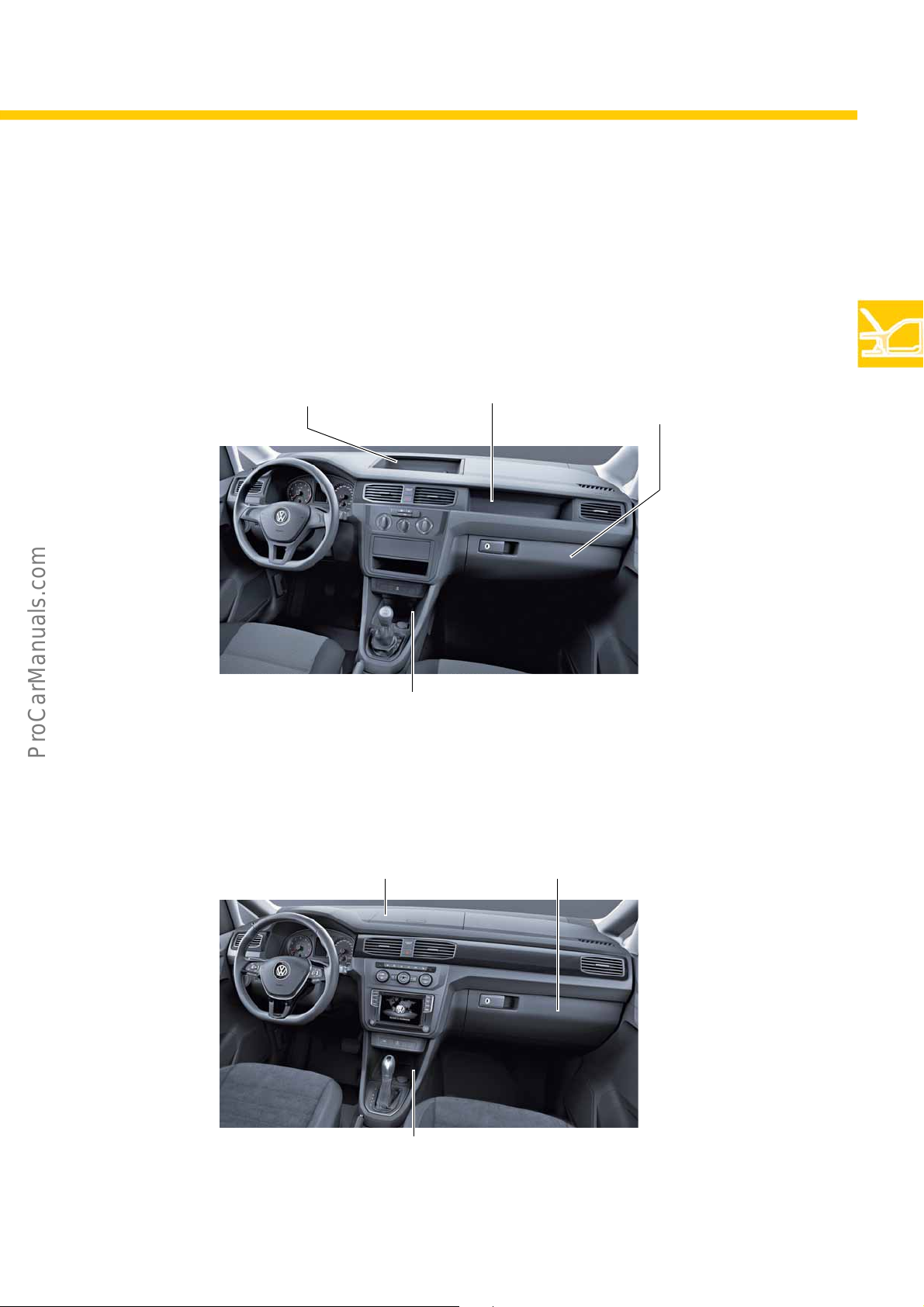
S560_060
Upper central storage compartment Open storage compartment Glove box,
lockable
Open storage compartment with 12 volt socket and
USB/Aux interface (depending on equipment)
The interior
Glove box,
lockable
Upper centre storage
compartment with flap
S560_059
Open storage compartment with 12 volt socket and
USB/Aux interface (depending on equipment)
Depending on equipment, there are two different dash panels in the Caddy 2016. Both variants appear in a new
design and offer numerous storage possibilities with a wider range of options. The convenience dash panel is
visually upgraded by decorative inlays and trims in different structures, colours and surface composition.
Convenience dash panel
11
Page 12
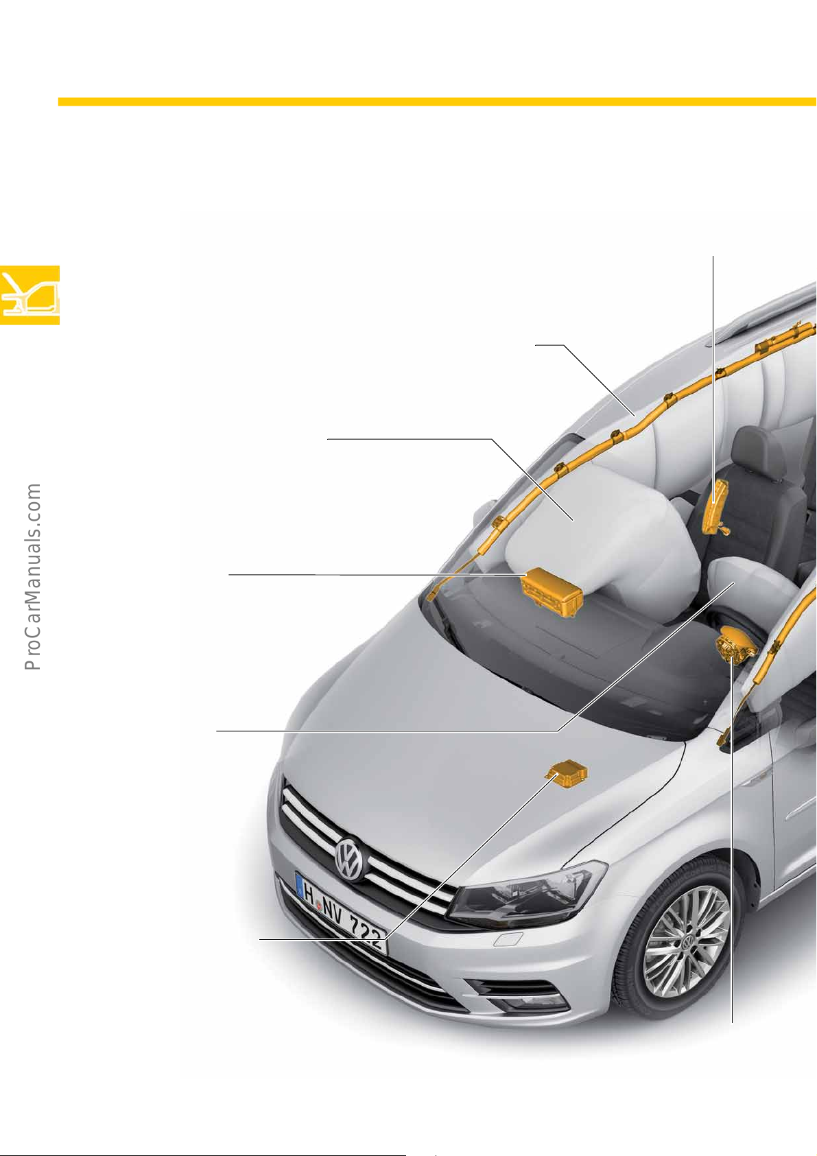
Body
Front passenger airbag
Module
Side airbag on front passenger side
Module
Front passenger airbag
Module
Driver's airbag
Driver's airbag
Airbag control unit with
crash sensor for front
airbags
Head airbag
Front passenger's side
(Front passenger and passenger
compartment)
Occupant protection
In vehicles without head curtain airbags for the driver
and passenger compartments, the side airbag on the
driver and front passenger sides is configured as a
head/thorax airbag.
12
Page 13
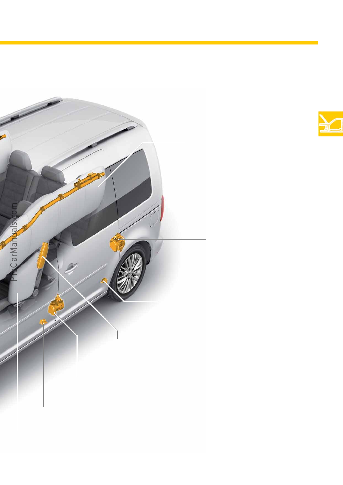
S560_152
Crash sensor, in B-pillar at bottom
(driver and FP sides)
Three-point seat belt with belt tensioner,
attached to the body
(driver and FP sides)
Crash sensor
in C-pillar at bottom
(driver and FP sides)
Head airbag
Driver side
(Driver and passenger compartment)
Module
Side airbag on driver side for vehicles with head curtain airbags
(Driver and passenger compartment)
Side airbag on driver side
Three-point seat belt with belt tensioner,
attached to the body
(driver and FP sides)
13
Page 14
Power units
The Caddy 2016 uses the most economical engines, and with the lowest emissions, that Volkswagen Commercial
Vehicles has ever offered.
TSI engines
The TSI engines (engine series EA211) from Volkswagen Commercial Vehicles combine low displacement,
turbocharging and direct injection to deliver a very even application of power. The maximum torque is available at
low engine speeds.
TGI engine
As the successor of the "Caddy EcoFuel" (with 2.0 l natural gas engine), the Caddy 2016 features a new 1.4 l TGI
engine. The turbocharged 4-cylinder inline engine has been further optimised for natural gas operation. Due to its
increased power and turbocharging, the engine delivers significantly improved acceleration and in-gear
acceleration values.
TDI engines
On the basis of a 2.0 l TDI engine (EA288 engine series) with common rail direct injection, customers can select
from 4 performance stages to meet their requirements. Each version will attract customers by extremely low
consumption and emissions values.
Emission standard EU6
All new engines in the Caddy 2016 meet the EU6 emission standard. As a result, exhaust post treatment to reduce
nitrous oxides is required for all diesel engines. An SCR system (Selective Catalytic Reduction system) is used for this
purpose.
TDI engines with emission standard EU5
Until further notice, the new "Caddy panel van" (except "Caddy panel van BlueMotion") and "Caddy Maxi panel
van" are also available with the corresponding EU5 TDI engines of the previous series (except 125 kW or 170 HP).
14
For more information about these engines, please refer to the Self-Study Programme no. 472
"The Caddy 2011".
Page 15
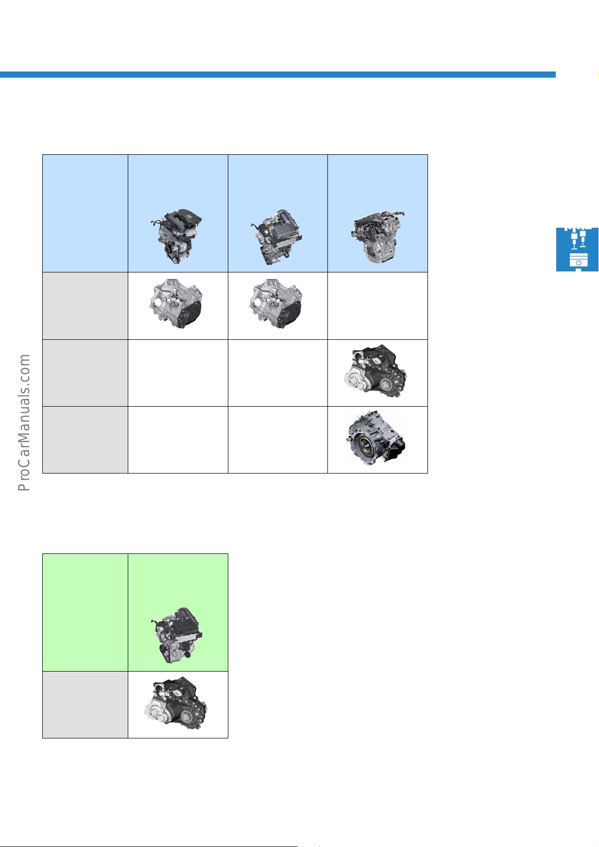
The TSI engines
5-speed
manual gearbox
0AF
6-speed
manual gearbox
02S
7-speed
dual clutch
gearbox
0CW
1.0 l 75 kW TSI engine
CHZG
1.2 l 62 kW TSI engine
CYVC
1.4 l 92 kW TSI engine
CZCB
The TGI engine (natural gas)
1.4 l 81 kW TGI engine
CPWA
6-speed
manual gearbox
02S
15
Page 16
Power units
S560_083
S560_133
40
20
1000 2000603000
160
120
80
40
80
Power [kW]
Torque [Nm]
0
Engine speed [rpm]
4000 5000
0
6000
200
100
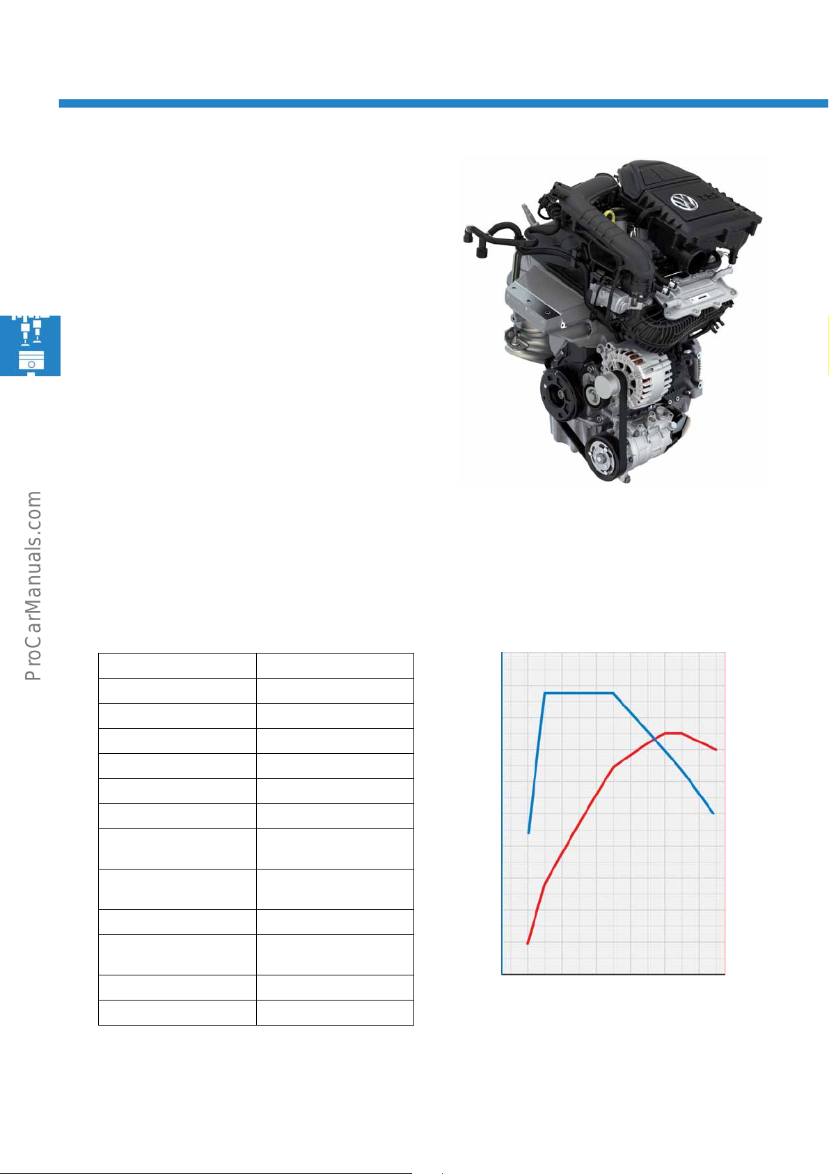
The 1.0 l 75 kW TSI engine
The 1.0 l 75 kW TSI engine comes from the EA211
engine series.
Technical features
• Exhaust turbocharger module with electric boost
pressure actuator
• Camshaft drive via a toothed belt
• Cylinder head with integrated exhaust manifold
• Coolant regulator housing with integrated coolant
pump
• Oil vane pump with drive directly from the
crankshaft
Technical data
Engine code CHZG
Cubic capacity 999 cm
Design 3-cylinder inline engine
Valves per cylinder 4
Bore 74.5 mm
Stroke 76.4 mm
Compression ratio 10.5 : 1
Max. power 75 kW at
Max. torque 175 Nm at
Engine management Bosch Motronic
Fuel Regular unleaded with
Turbocharger Wastegate turbocharger
Emissions standard EU6
3
5000 rpm
1500 – 3500 rpm
RON 95
Torque and power diagram
16
Page 17
The 1.2 l 62 kW TSI engine
S560_108
S560_082
40
20
1000 2000603000
160
120
80
40
80
Power [kW]
Torque [Nm]
0
Engine speed [rpm]
4000
5000
0
6000
200
100
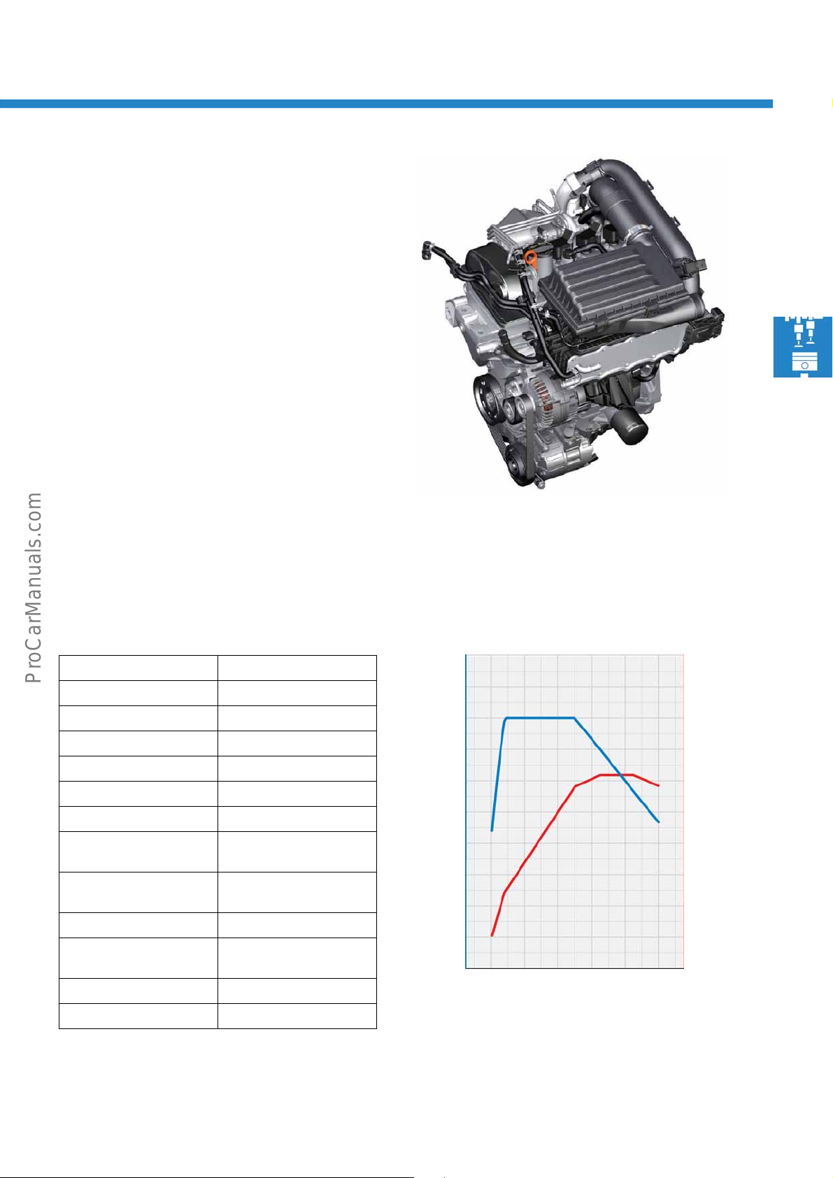
The 1.2 l 62 kW TSI engine also belongs to
the EA211 engine series.
Technical features
• Exhaust turbocharger module with electric boost
pressure actuator
• Camshaft drive via a toothed belt
• Cylinder head with integrated exhaust manifold
• Coolant regulator housing with integrated coolant
pump
• Duo-centric oil pump with drive directly from the
crankshaft
• Variable intake valve timing
Technical data
Engine code CYVC
Cubic capacity 1197 cm
Design 4-cylinder inline engine
Valves per cylinder 4
Bore 71 mm
Stroke 75.6 mm
Compression ratio 10.5 : 1
Max. power 62 kW at
Max. torque 160 Nm at
Engine management Bosch Motronic
Fuel Regular unleaded with
Turbocharger Wastegate turbocharger
Emissions standard EU6
3
4300 – 5300 rpm
1400 – 3500 rpm
RON 93
Torque and power diagram
17
Page 18
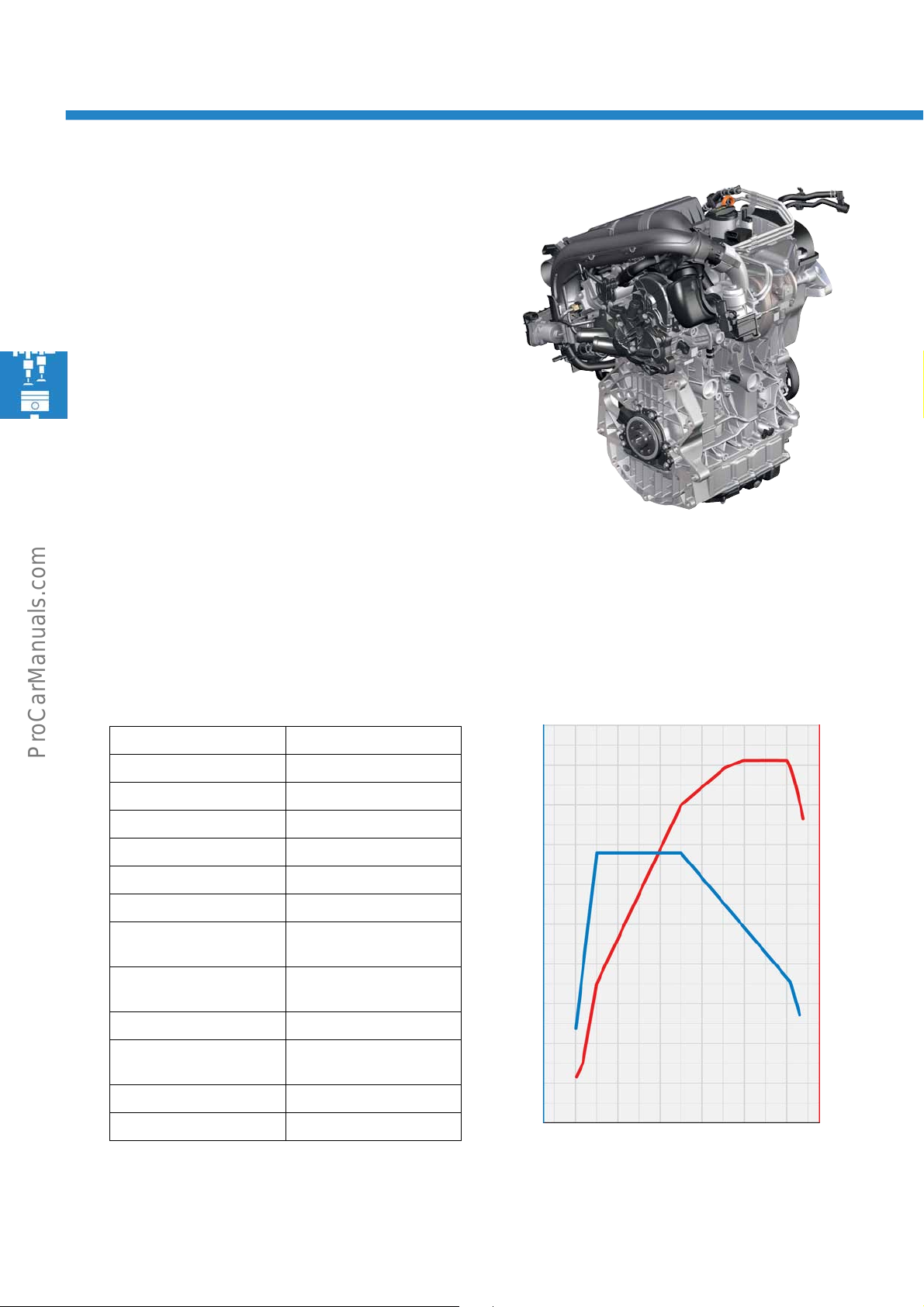
Power units
S560_010
40
20
1000 2000603000
250
200
150
100
80
Power [kW]
Torque [Nm]
0
Engine speed [rpm]
4000
5000
50
6000
S560_084
300
100
The 1.4 l 92 kW TSI engine
The 1.4 l 92 kW TSI engine also belongs to
the EA211 engine series.
Technical features
• Exhaust turbocharger module with electric boost
pressure actuator
• Camshaft drive via a toothed belt
• Cylinder head with integrated exhaust manifold
• Externally geared oil pump
• Variable intake valve timing
Technical data
Engine code CZCB
Cubic capacity 1395 cm
Design 4-cylinder inline engine
Valves per cylinder 4
Bore 74.5 mm
Stroke 80 mm
Compression ratio 10.5 : 1
Max. power 92 kW at
Max. torque 220 Nm at
Engine management Bosch Motronic
Fuel Regular unleaded with
Turbocharger Wastegate turbocharger
Emissions standard EU6
3
5000 – 6000 rpm
1500 – 3500 rpm
RON 95
Torque and power diagram
18
Page 19
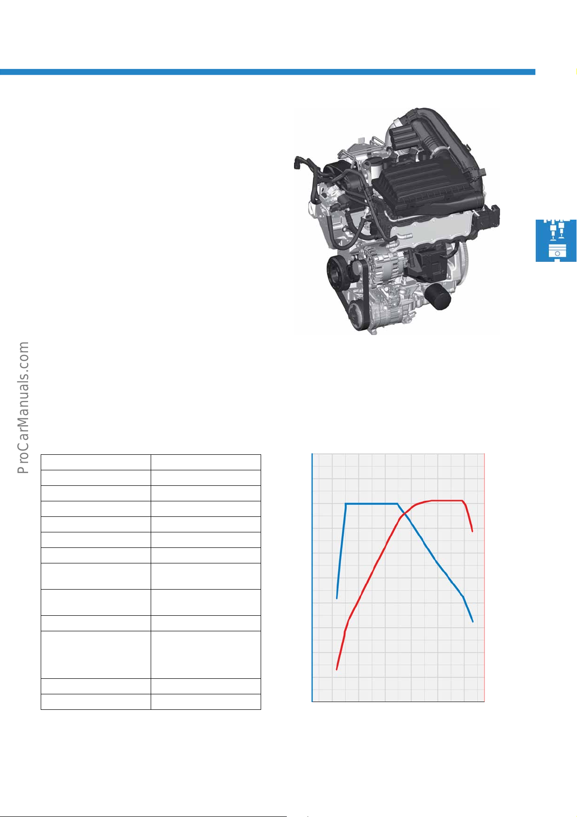
The 1.4 l 81 kW TGI engine
S560_012
60
80
Power [kW]
Torque [Nm]
40
20
0
160
120
40
200
80
1000 2000 3000
Engine speed [rpm]
4000 5000
6000
S560_076
(natural gas)
This engine was launched in the 2014 model year for
the Golf and Golf Variant. It differs from the 1.4 l
90 kW TSI engine only in that its components are
apted for natural gas drive.
ad
Technical features
• One engine control unit for natural gas and petrol
mode
• Electronic gas pressure regulator with a
mechanical and electronic pressure reduction
stage
• Gas rail with temperature and pressure sensor
Technical data
Engine code CPWA
Cubic capacity 1395 cm
Design 4-cylinder inline engine
Valves per cylinder 4
Bore 74.5 mm
Stroke 80.0 mm
Compression ratio 10.5 : 1
Max. power 81 kW at
Max. torque 200 Nm at
Engine management Bosch Motronic
Fuel Natural gas H
Turbocharger Wastegate turbocharger
Emissions standard EU6
3
4800 – 6000 rpm
1500 – 3500 rpm
Natural gas L with reduced
range
Regular unleaded RON 95
Torque and power diagram
19
Page 20
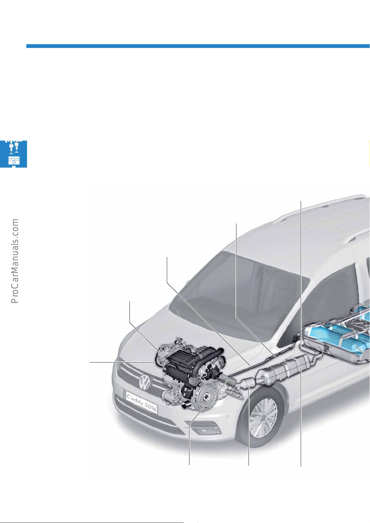
Power units
High-pressure
Natural gas line
Fuel line
Petrol
Gas pressure regulator with sensor for tank
pressure G400
Hydraulic valve for gas mode N372
Low-pressure
Natural gas line
SilencerUnderbody
Catalytic
Decoupling element
Tailpipe
in front of the rear axle
Running on natural gas
In the Caddy 2016, a new natural gas engine is being launched with the 1.4 l TGI engine of the EA211 engine
series. It differs from the purely petrol-operated variant in that its components have been adapted for running on
natural gas. The adaptations have been made because natural gas not only burns more cleanly than petrol but
also has a higher knock resistance. For example, the octane number of natural gas H is up to RON 130. This
its an earlier ignition time without engine knock during combustion. The efficiency increases, and so does the
perm
combustion pressure and combustion temperature in the combustion chamber.
Furthermore, natural gas is very dry and does not have lubricating properties such as petrol.
20
Page 21
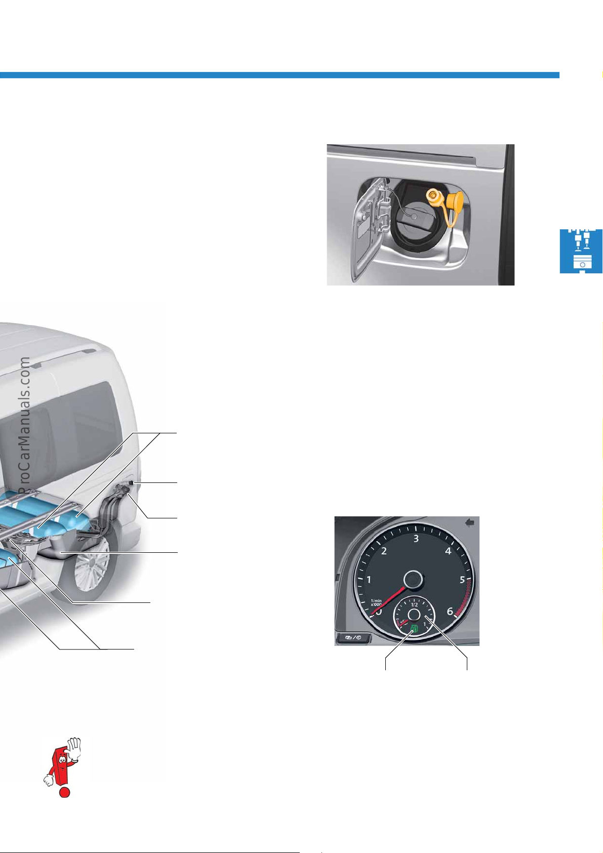
Refuelling natural gas
S560_104
S560_103
Warning light for
natural gas mode
K192
Natural gas gauge
G411
S560_100
Natural gas fuel tank
(rear rack)
Filler pipe
Natural gas
Filler pipe
Petrol
Plastic cover
Petrol fuel tank
Natural gas fuel tank
(front rack)
The gas filler pipe is located on the left side of the
vehicle behind the tank flap next to the petrol filler
pipe. The Caddy 2016 has 4 or 5 natural gas tanks
addy Maxi), which are arranged in 2 racks on the
(C
floor of the vehicle. Between these is located the
petrol tank with a capacity of about 13 litres. The
natural gas fill quantity in the Caddy is about 26 kg
in the Caddy Maxi about 37 kg.
and
Natural gas gauge G411
The dash panel insert contains the natural gas gauge
G411 in the left round instrument, with the warning
light for natural gas mode K192. This lights yellow
when both fuel types have been consumed down to
the reserve level. The warning light illuminates green
if the vehicle is in natural gas mode. The green warning light goes out when the natural gas supply has
en used up. The engine switches over to petrol
be
mode.
For more information about natural gas technology, please refer to the Self-Study Programme no. 528
"Running on natural gas in the Golf/Golf Variant TGI BlueMotion".
21
Page 22
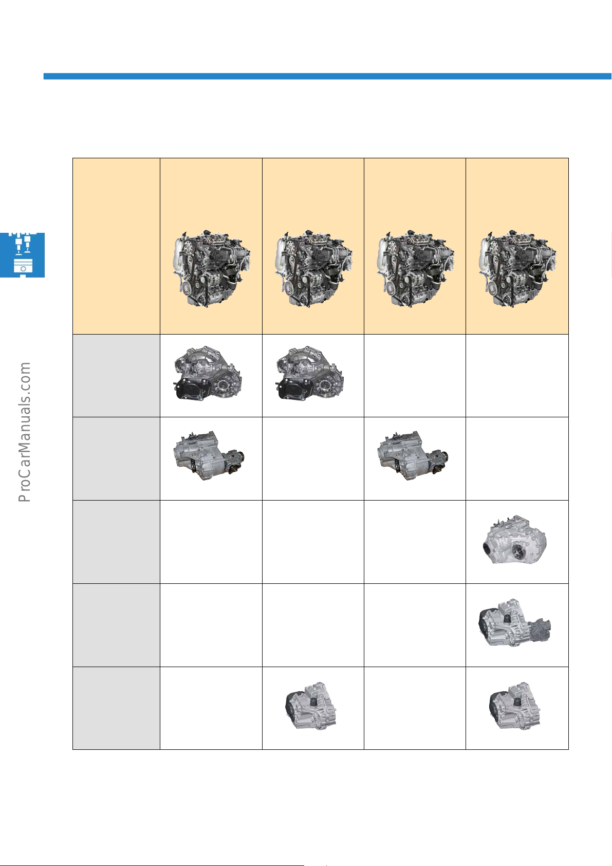
Power units
The TDI engines
5-speed
manual gearbox
0A4
6-speed
manual gearbox
02Q-A
2.0 l 55 kW
TDI engine
CUUF
2.0 l 75 kW
TDI engine
CUUD
2.0 l 90 kW
TDI engine
CUUE
2.0 l 110 kW
TDI engine
CUUB
6-speed
manual gearbox
02Q-F
6-speed
dual clutch
gearbox
02E-A
6-speed
dual clutch
gearbox
02E-F
22
Page 23
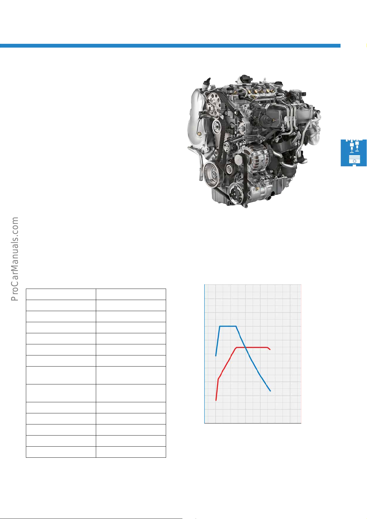
The 2.0 l 55 kW TDI engine
S560_011
S560_078
40
20
1000 2000603000
250
200
150
100
80
Power [kW]
Torque [Nm]
0
Engine speed [rpm]
4000 5000
50
6000
300
100
A new 2.0 l TDI engine is used in the Caddy 2016.
The engine is in the EA288 engine series.
Technical features
• Exhaust purification module with SCR system
• High and low-pressure exhaust gas recirculation
• Thermal management with coolant pump with on/
off function
• Suction pipe module with water-cooled charge air
cooler
• Bosch common rail injection system
Technical data
Engine code CUUF
Cubic capacity 1968 cm
Design 4-cylinder inline engine
Valves per cylinder 4
Bore 81 mm
Stroke 95.5 mm
Compression ratio 16.2 : 1
Max. power 55 kW at
Max. torque 225 Nm at
Engine management Bosch EDC 17
Fuel Diesel acc. to DIN EN 590
Turbocharger VTG turbocharger
Exhaust gas recirculation Yes
Emissions standard EU6 with SCR system
3
2400 – 4500 rpm
1200 – 2300 rpm
Torque and power diagram
23
Page 24
Power units
S560_011
S560_079
40
20
1000 2000603000
250
200
150
100
80
Power [kW]
Torque [Nm]
0
Engine speed [rpm]
4000 5000
50
6000
300
100
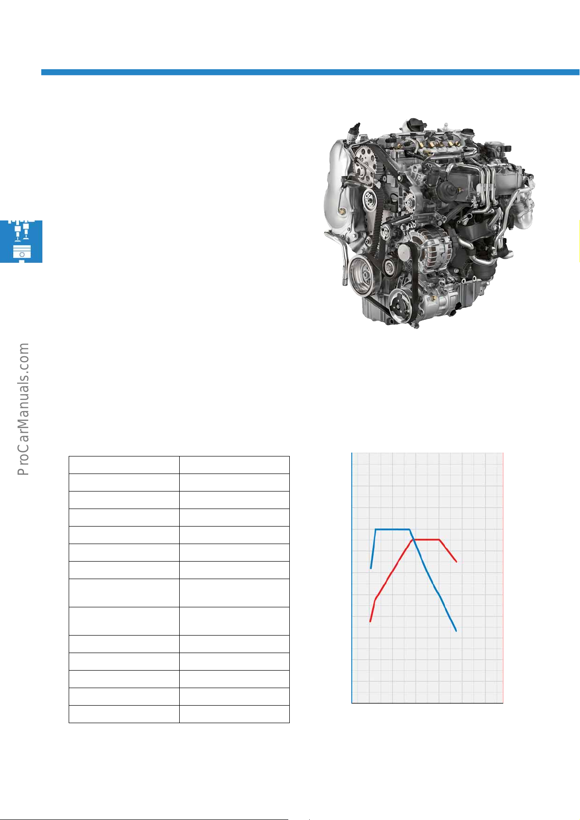
The 2.0 l 75 kW TDI engine
This engine also belongs to the EA288 engine series.
The power and torque are controlled by the engine
management system.
Technical features
• Exhaust purification module with SCR system
• High and low-pressure exhaust gas recirculation
• Thermal management with coolant pump with on/
off function
• Suction pipe module with water-cooled charge air
cooler
• Bosch common rail injection system
Technical data
Engine code CUUD
Cubic capacity 1968 cm
Design 4-cylinder inline engine
Valves per cylinder 4
Bore 81 mm
Stroke 95.5 mm
Compression ratio 16.2 : 1
Max. power 75 kW at
Max. torque 250 Nm at
Engine management Bosch EDC 17
Fuel Diesel acc. to DIN EN 590
Turbocharger VTG turbocharger
Exhaust gas recirculation Yes
Emissions standard EU6 with SCR system
3
2900 – 4000 rpm
1300 – 2800 rpm
Torque and power diagram
24
Page 25
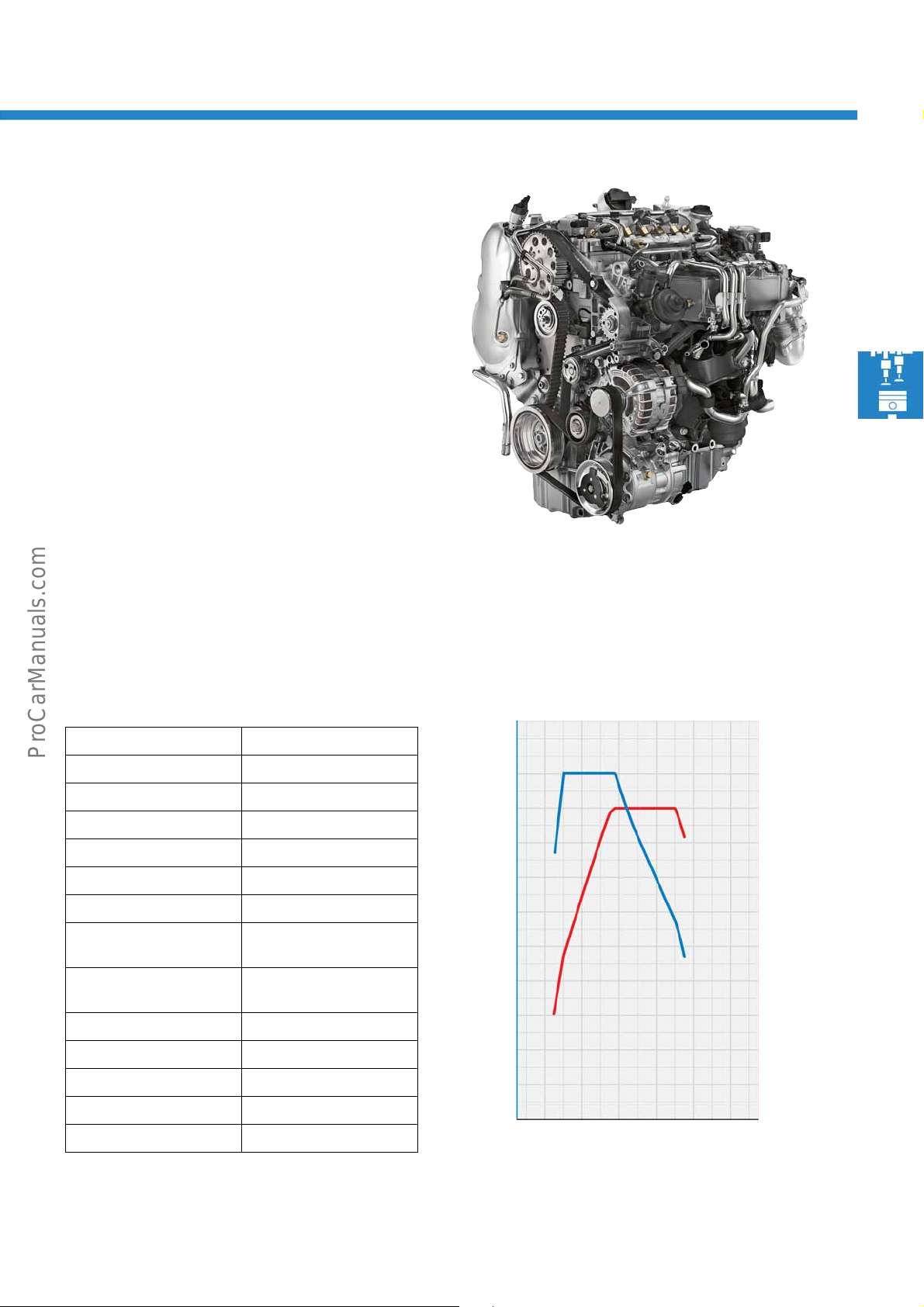
The 2.0 l 90 kW TDI engine
S560_011
S560_080
40
20
1000 2000603000
250
200
150
100
80
Power [kW]
Torque [Nm]
0
Engine speed [rpm]
4000 5000
50
6000
300
100
This engine also belongs to the EA288 engine series.
The power and torque are controlled by the engine
management system.
Technical features
• Exhaust purification module with SCR system
• High and low-pressure exhaust gas recirculation
• Thermal management with coolant pump with on/
off function
• Suction pipe module with water-cooled charge air
cooler
• Bosch common rail injection system
Technical data
Engine code CUUE
Cubic capacity 1968 cm
Design 4-cylinder inline engine
Valves per cylinder 4
Bore 81 mm
Stroke 95.5 mm
Compression ratio 16.2 : 1
Max. power 90 kW at
Max. torque 300 Nm at
Engine management Bosch EDC 17
Fuel Diesel acc. to DIN EN 590
Turbocharger VTG turbocharger
Exhaust gas recirculation Yes
Emissions standard EU6 with SCR system
3
2900 – 4500 rpm
1500 – 2800 rpm
Torque and power diagram
25
Page 26

Power units
S560_011
S560_081
40
20
1000 2000603000
250
200
150
100
80
Power [kW]
Torque [Nm]
0
Engine speed [rpm]
4000 5000
50
6000
300
350
100
120
The 2.0 l 110 kW TDI engine
This engine also belongs to the EA288 engine series.
At the moment, it is the most powerful diesel engine in
the Caddy 2016.
Technical features
• Exhaust purification module with SCR system
• High and low-pressure exhaust gas recirculation
• Thermal management with coolant pump with on/
off function
• Suction pipe module with water-cooled charge air
cooler
• Bosch common rail injection system
Technical data
Engine code CUUB
Cubic capacity 1968 cm
Design 4-cylinder inline engine
Valves per cylinder 4
Bore 81 mm
Stroke 95.5 mm
Compression ratio 16.2 : 1
Max. power 110 kW at
Max. torque 340 Nm at
Engine management Bosch EDC 17
Fuel Diesel acc. to DIN EN 590
Turbocharger VTG turbocharger
Exhaust gas recirculation Yes
Emissions standard EU6 with SCR system
3
3500 – 4000 rpm
1750 – 3000 rpm
Torque and power diagram
26
Page 27
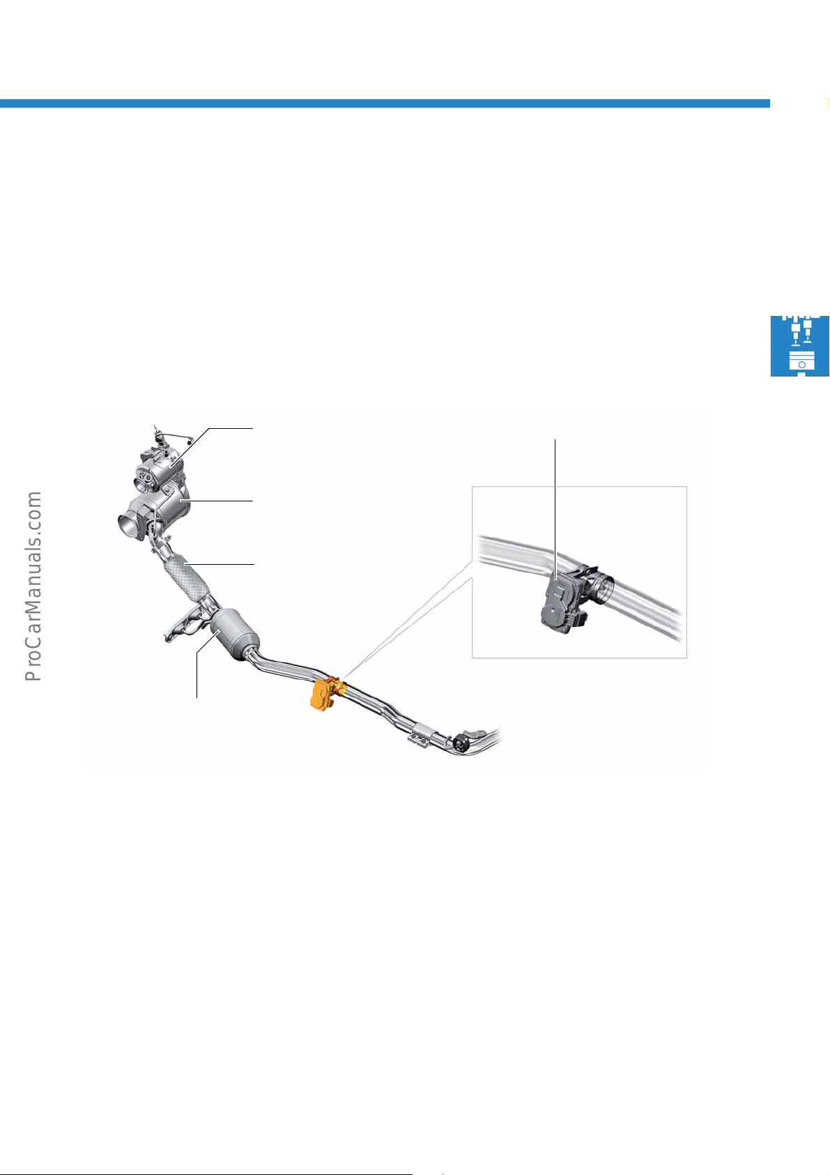
The exhaust flap control unit J883
S560_136
Oxidising catalytic converter
Diesel particulate filter
Flex tube
Exhaust flap control unit J883
Trap catalytic converter
The task of the control unit is to generate a slight back
pressure after the diesel particulate filter, using an
exhaust flap operated by an electric motor. The
resulting positive pressure of 30 – 40 mbar above
haust gas pressure produces a positive flow
ex
gradient (purge rate) in the exhaust gas recirculation
cooler and the exhaust gas recirculation valve
arranged after it.
The exhaust gas recirculation valve controls the
ount of returned exhaust gases depending on the
am
characteristic map. This back pressure is measured by
the pressure sensor 1 for exhaust gas G450.
Trap catalytic converter
The combined diesel particulate filter with SCR
catalytic converter is followed by a trap catalytic
converter which carries out two tasks:
The carbon monoxide (CO) resulting from soot
generation is oxidised by the coating containing
re
precious metals, to produce carbon dioxide (CO
As its 2nd task, the trap catalytic converter ensures
t no ammonia (NH
tha
under any circumstances. NH
nitrogen (N
) and water (H2O).
2
) leaves the exhaust system
3
is oxidised into
3
2
).
27
Page 28
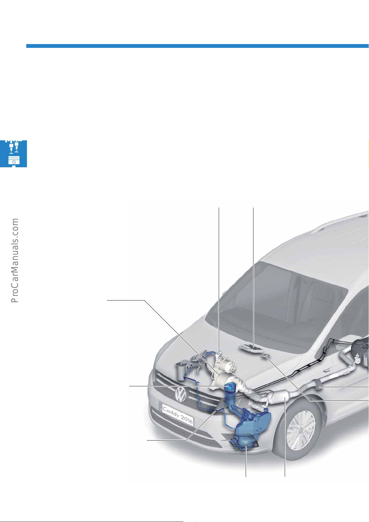
Power units
Injector for reducing agent N474 Engine control unit J623
Exhaust purification
module
Filler neck for reducing agent
Heated metering line to the injector for
reducing agent N474
Reducing agent tank with pump module Trap catalytic converter
The exhaust post-treatment with SCR system
In order to achieve the EU6 emissions limits, a Selective Catalytic Reduction system (SCR system) is used in the
Caddy 2016. This means only the nitrogen oxides specifically
The nitrogen oxides (NO
To do this, a reducing agent is continuously injected into the exhaust gas stream.
) are converted in the reduction catalytic converter into nitrogen (N2) and water (H2O).
x
Overview
are reduced amongst the exhaust gas constituents.
28
Page 29
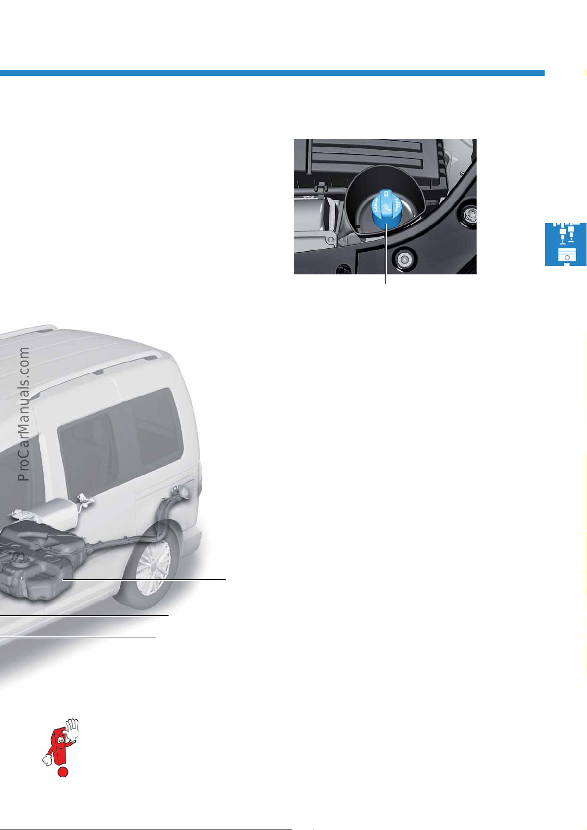
Control unit for reducing agent heating J891
Exhaust flap control unit J883
Diesel fuel tank
S560_015
Filling the tank for reducing agent
S560_024
Filler neck for reducing agent
In addition to the fuel tank with a capacity of about
55 litres (front-wheel drive), there is also a reducing
agent tank with a capacity of about 9 litres in the
engine compartment. This capacity achieves a range
of about 6000 km.
The tank for reducing agent is replenished via a filler
ction in the engine compartment at the front left
conne
out of replenishment containers, and is closed by a
blue tank cap.
For more information about exhaust post-treatment, please refer to the Self-Study Programme no. 446
"The 2.5 l TDI EURO V engines with SCR system in the Crafter - design and function".
29
Page 30
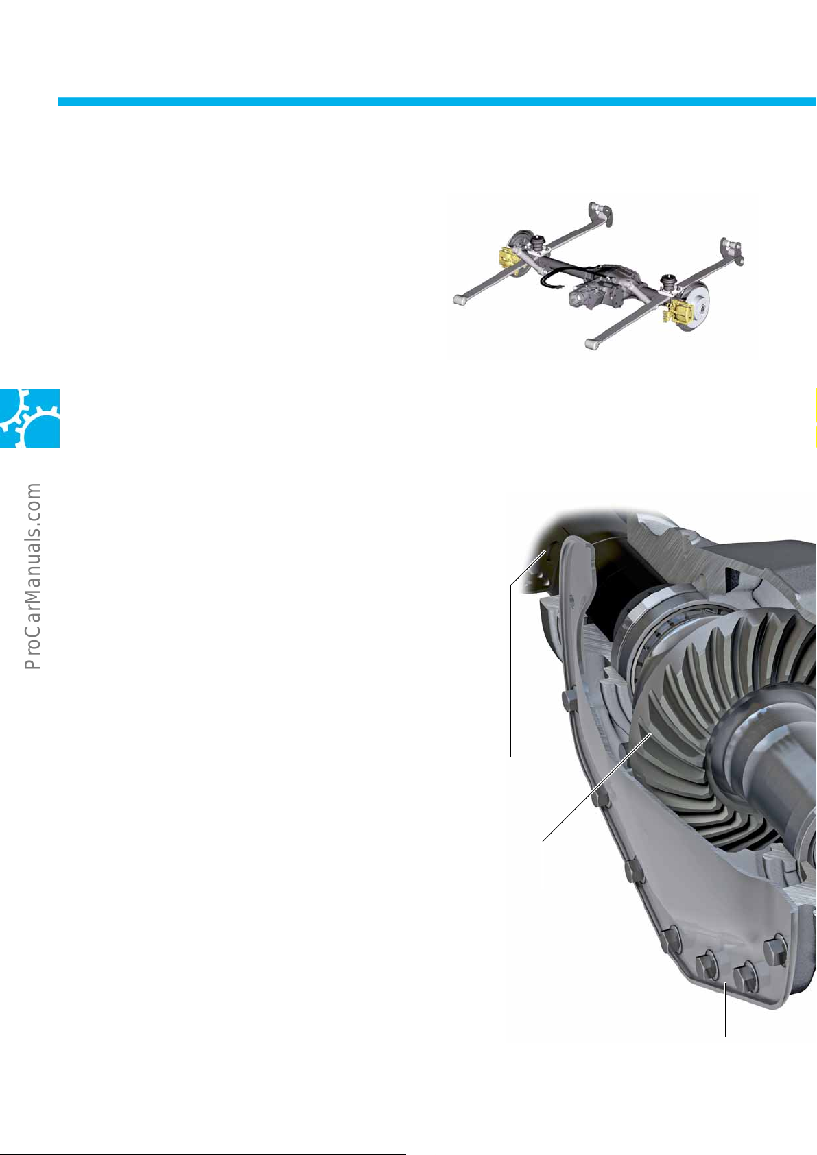
Power transmission
S560_054
Crown wheel with hypoid
gearing
Left drive shaft
Rear end cover
The 4WD coupling generation V
In the Caddy 2016, 4-wheel drive is offered in all
vehicle variants with the following engines:
• 2.0 l 90 kW TDI engine
•
2.0 l 110 kW TDI engine
The 4WD coupling is integrated into the rear final
d
rive. The 4WD coupling between the front and rear
final drives controls the drive torque to the rear axle.
It directs the required torque to the rear axle
depending on the pressure in the multi-plate clutch.
Structure and function
The Haldex coupling of generation V is characterised
primarily by a new pressure control. The hydraulic
pressure required for the 4WD coupling is generated
by a pump with centrifugal force controller. This
technology has allowed the weight to be reduced
compared to generation IV of the 4WD coupling
ldex) by 1.7 kg.
(Ha
The control logic in the various driving situations has
b
een taken from generation IV of the 4WD coupling
ldex), see Self-Study Programme no. 414
(Ha
MOTION with 4WD coupling generation IV".
"4
30
Page 31
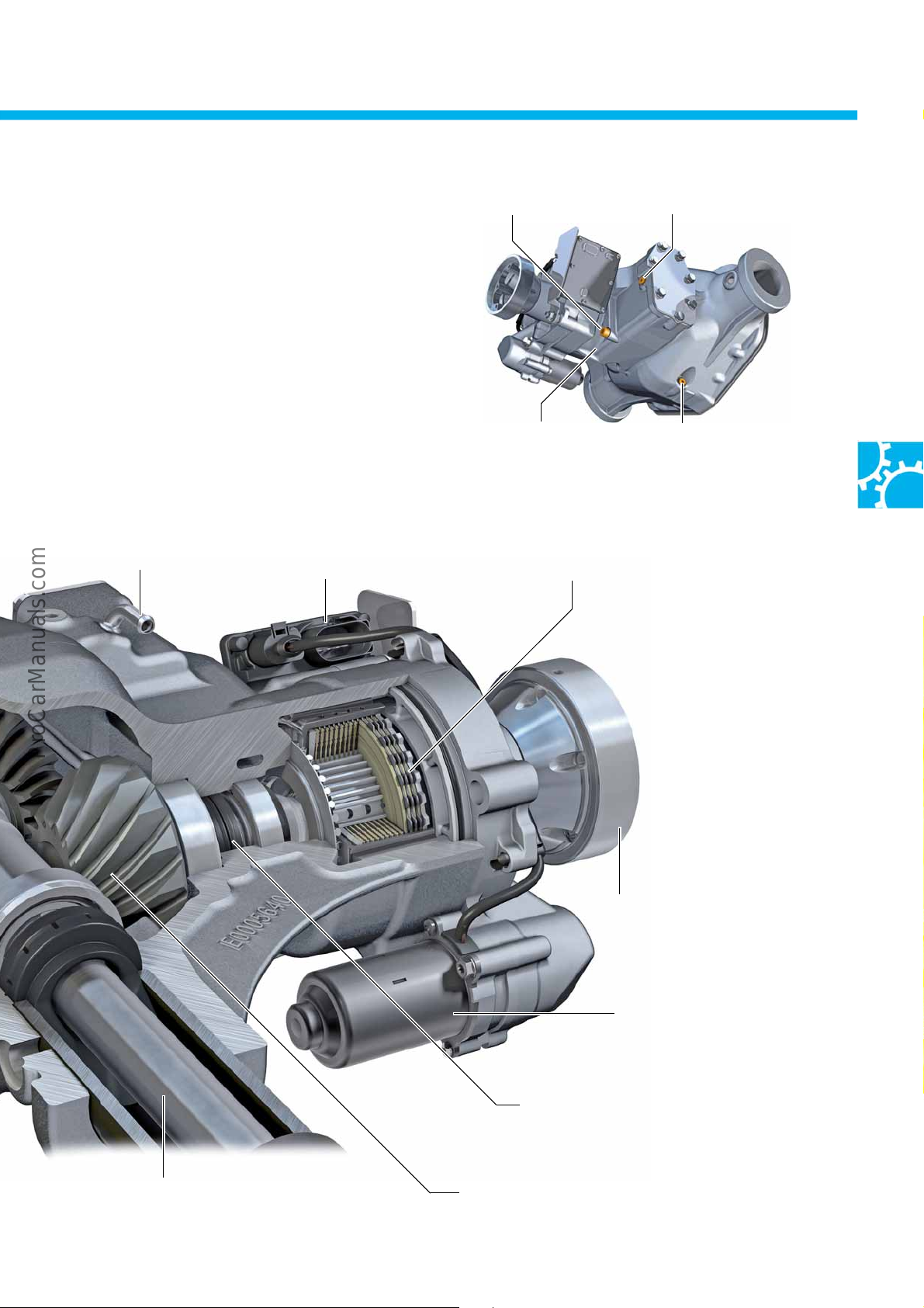
Oil fill
S560_094
Final drive oil drain plug
Haldex oil drain plug Haldex oil filler plug
Final drive oil filler plug
(concealed)
Drive pinion
Right drive shaft
Control unit for 4WD
coupling J492
Clutch cage with clutch pack
(Haldex coupling)
Rear final drive breather
Pump for
Haldex coupling V181
Double oil seal
Flange for holding the propshaft
S560_086
The oil is changed every 3 years in the Caddy, without
any limitation in terms of mileage. Please use the
correct oil filler and drain plug! For more information,
refer to the electronic service information system
(ElsaPro).
31
Page 32

Running gear
Brake system of the
modular transverse matrix
Behind the Volkswagen badge:
Control unit for distance control J428
Overview of the running gear and driver assist systems
The overview shows important running gear equipment of the Caddy 2016 that is fitted as standard and
optionally. It can be equipped with standard running gear, spor
Running gear
The design of the running gear and brake system is
based on the technology of the previous model:
• Suspension strut front axle according to the
herson principle with double wishbones and
McP
anti-roll bar
• Rigid rear axle on leaf springs with load-
dependent dampers and anti-roll bar as well as
4WD coupling generation V (Haldex) depending
on engine and model
• Electromechanical power steering
• Brake system of the modular transverse matrix
• ABS/ESC Continental MK 100
ts running gear or reinforced suspension.
The ESP unit is fitted on the right longitudinal member
the engine compartment. It comprises the control
in
unit for ABS J104 and the hydraulic unit.
32
Page 33
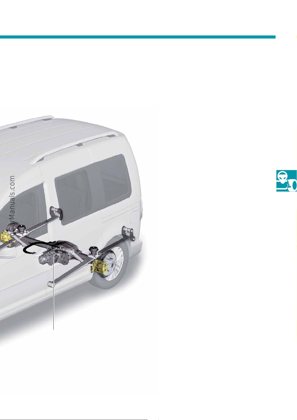
S560_052
Rear axle with 4WD coupling
(Haldex V)
Driver assistance systems
• Cruise control system (CCS)
• Speed limiter
• Adaptive cruise control (ACC)
• Front scan system (Front Assist) with
automatic emergency braking (AEB)
• Multicollision brake
• Main beam assistant (FLA)
• Parking distance control
• Optical 360° parking system (OPS)
• Park Assist system 2.0 (Park Assist)
•Rear view camera
• Tyre pressure monitor (TPM+)
• Fatigue detection (MKE)
Control unit for ABS J104
The yaw rate sender G202, the lateral acceleration
sender G200 and the longitudinal acceleration
sender G251 are integrated in the ABS control unit
J104. In addition to the familiar functions from the
previous model, the ABS control unit additionally
provides assistance systems such as the tyre pressure
monitoring display RKA+ and the multicollision brake.
33
Page 34
Running gear
S560_055
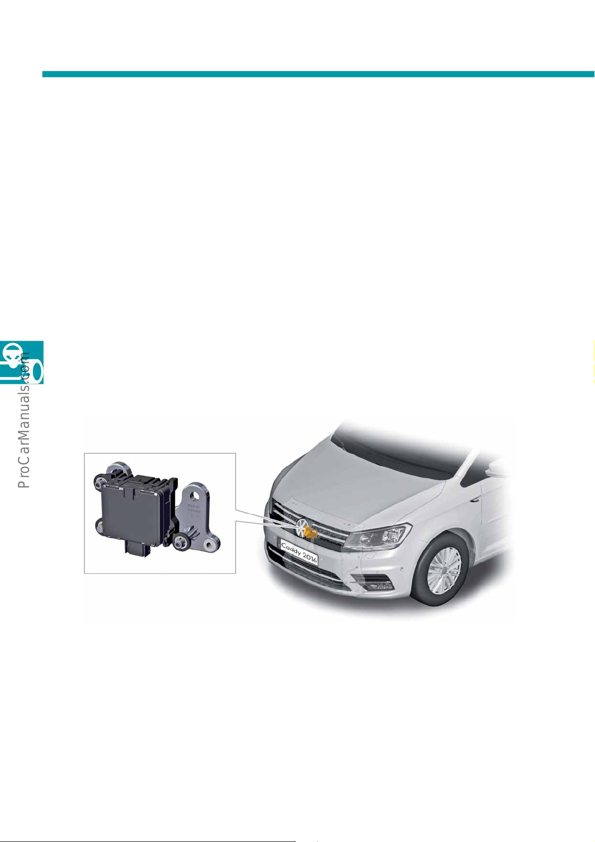
Control unit for distance control J428
Adaptive cruise control ACC
Adaptive cruise control ACC is a speed control system with intelligent control of the vehicle speed. The system
accelerates and decelerates comfortably.
Function
If there is no vehicle in front, ACC operates like a cruise control system. If the radar sensor detects a vehicle driving
in front in the same lane, ACC decelerates the vehicle if necessary and keeps it at the preselected following
distance. In combination with a dual clutch gearbox (DSG), the vehicle can be decelerated automatically to a
standstill and stopped.
In vehicles with a manual gearbox, the vehicle is automati
system switches off automatically at speeds less than 20 km/h.
cally accelerated or braked to the desired speed. The
Control unit for distance control J428
The control unit for distance control J428 is fitted behind the Volkswagen badge so as to detect the traffic situation
in front of the vehicle. The control unit is connected to the Extended CAN in the Caddy 2016. A radar sensor is
integrated in the control unit.
34
Page 35
Operation
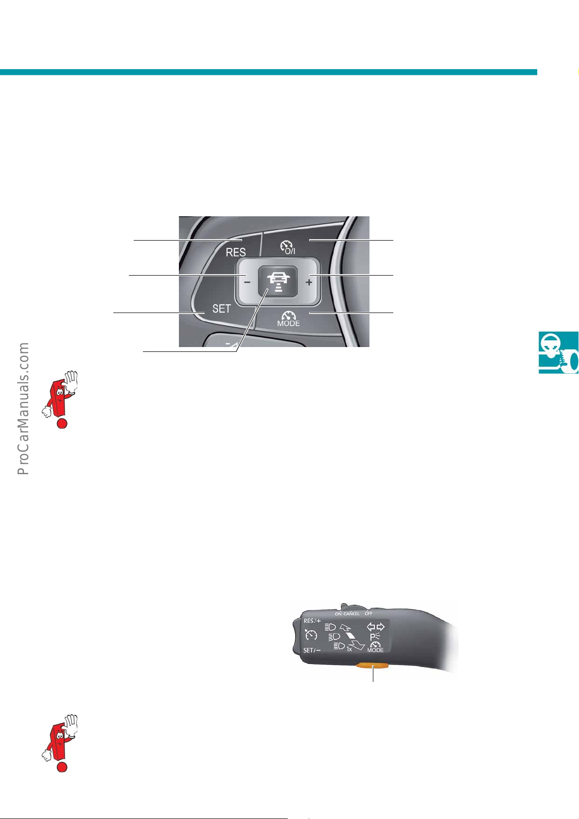
S560_057
Resume ACC control
Decelerating during
ACC control
Activating ACC
Set the distance level
Switching ACC on/off/
cancelling
Accelerating during ACC
control
Change between ACC and
speed limiter
S560_093
Change between cruise control
system and speed limiter
The radar sensor continuously measures the distance and speed of the vehicle driving in front. Using the ACC
controls on the multifunction steering wheel, the system can be activated and deactivated, and the required speed
and following distance can be set. The dash panel insert displays all relevant information about the system such as
the required speed and warning messages.
For more information about the driver assist systems, refer to Self-Study Programme no. 516
"The Golf 2013 driver assist systems".
Speed limiter
The speed limiter has the task of limiting the vehicle's speed to a preset maximum speed, even if the driver presses
the accelerator pedal to demand a higher speed. The function is implemented by precise interventions in the
engine management system. Automatic brake interventions are not carried out by the speed limiter.
Operation
The speed limiter can be operated using the left steering column lever or the buttons on the multifunction steering
wheel, depending on the equipment.
It is possible to temporarily overrule the preset limit
peed using kickdown. There is a visual warning for
s
the period during which the limit value is exceeded,
as well as a one-time audible warning each time the
vehicle is driven faster than the limit value.
For detailed information about operating the speed limiter, refer to the owner's manual of the vehicle.
35
Page 36

S560_098
Front camera for driver
assist systems R242
Control unit for main
beam assist J844
Running gear
S560_097
The high beam assistant (FLA)
The high-beam assistant permits the high beams to be
switched on and off automatically depending on the
traffic situation. The "eye" of the system is an RGB
camera with a resolution of about 0.5 megapixels
that is accommodated in the mirror base.
The main beam assist is integrated in the data bus
twork via the powertrain CAN bus for the dash
ne
panel insert.
For more information about the main beam assist, please refer to the Self-Study Programme no. 498
"The Golf convertible 2012".
36
Page 37
The Park Assist system 2.0
S560_085
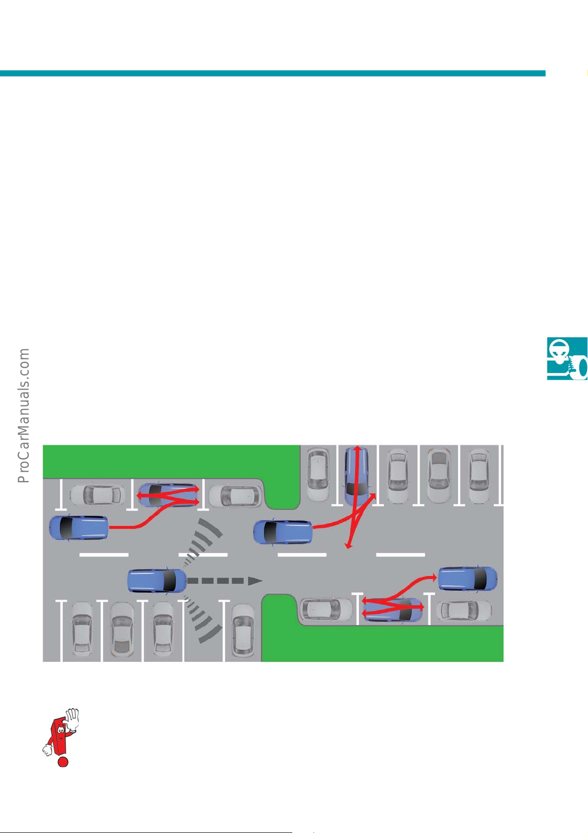
The Park Assist system assists the driver when entering and exiting parking spaces, and during manoeuvring. It
carries out the steering movements automatically. The driver only needs to engage the corresponding gear, press
the accelerator and the brake. The driver can terminate the function of the Park Assist system at any time, and take
over control. 6 sensors are mounted on the front of the vehicle and 6 on the rear for the Park Assist system. This
also enables the 360° OPS function.
The functions of the Park Assist system are:
• The park pilot, also referred to as parking distance control (PDC). This is also available without Park Assist
system and must also be activated in vehicles with Park Assist system, e.g. when parking forwards.
• The park steering function for the active parking process.
• Perpendicular parking
• Parking on bends
• Parallel parking
- with two or all wheels on pavements
- between other obstacles (trees, bushes or motorcycles)
• Driving out of a parallel parking space
• ESP intervention when parking if the speed is too fast or there is a risk of collision to reduce damage
For more information about 360° OPS, please refer to Self-Study Programme no. 517 "The Golf 2013
electric". For more information about the Park Assist system 2.0 with all components, refer to the SelfStudy Programme no. 494 "The Park Assist system 2.0".
37
Page 38
Running gear
S560_116
The tyre pressure monitoring display (RKA+)
Task
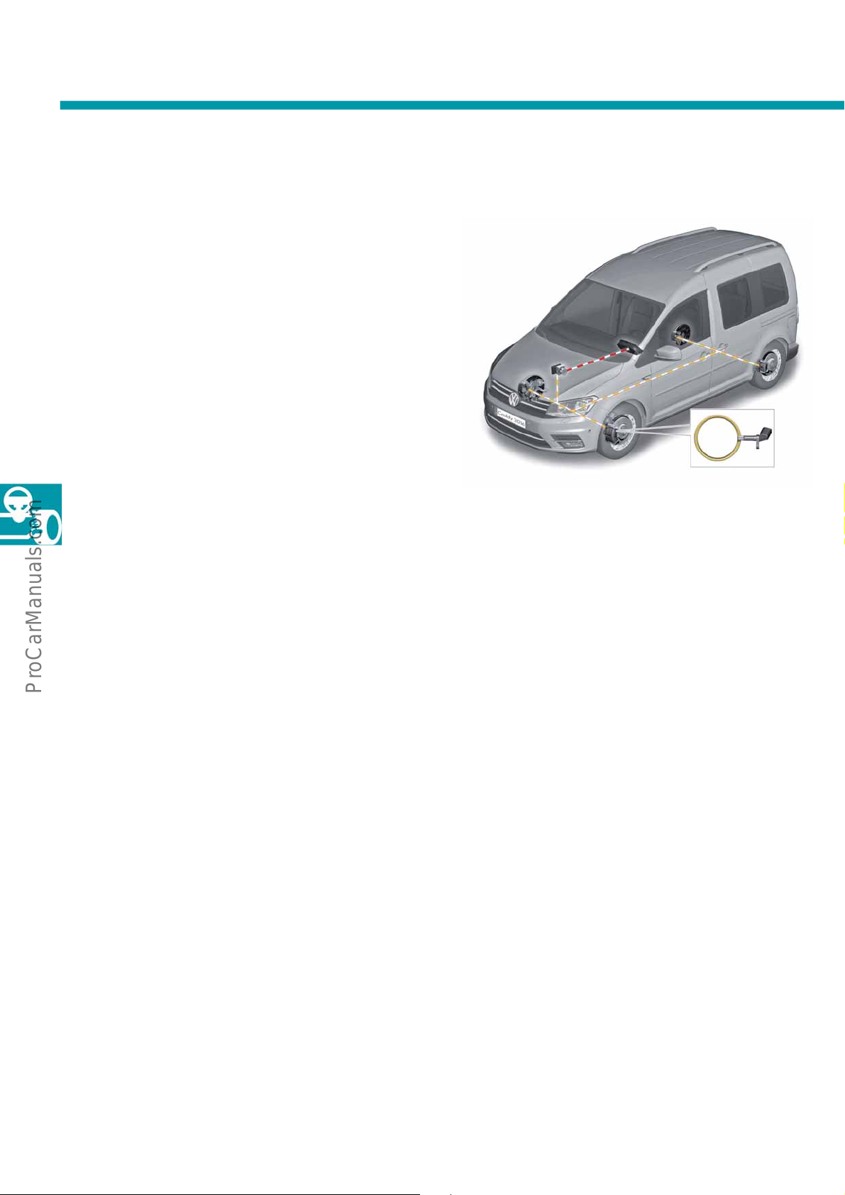
The tyre pressure monitoring display (TPM+) uses the
wheel speed sensors G44 – G47 to compare the
rolling circumference and vibration behaviour of the
individual wheels.
The vibration behaviour and the rolling circumference
the wheels change when the tyre pressure changes.
of
A change in the tyre pressure at one or more wheels
is i
ndicated on the tyre pressure monitoring display in
the multifunction display on the dash panel insert. No
additional sensors are required in the tyres. The
change in the tyre pressure is detected by a
calculation model in the ABS control unit J104.
Function
The tyre pressure monitor display system is part of the
software in the ABS control unit J104.
Event memory entries for the tyre pressure monitoring
splay are stored in the ABS control unit.
di
The tyre monitor display must have its teach-in
pr
ocess repeated after the following work:
• Change of tyre pressure
•
Changing one or more wheels
• Interchanging wheels, e.g. from front to rear
After the teach-in process, the system learns the
racteristic parameters of the new pressure and
cha
tyre conditions at various speed intervals and stores
them.
Changes to the rolling circumference and the
ration behaviour of a wheel are displayed on the
vib
dash panel insert by the tyre pressure monitoring
display warning lamp K220 lighting up.
The rolling circumference and the vibration behaviour
can change due to:
• Insufficient tyre pressure
• Damage to the tyre
• One-sided loading of vehicle
• Influence of snow chains
• Changing a wheel
• Increased load on one axle, e.g. when towing a
trailer
• Operation with temporary spare wheel
38
Page 39
The multicollision brake
S560_135
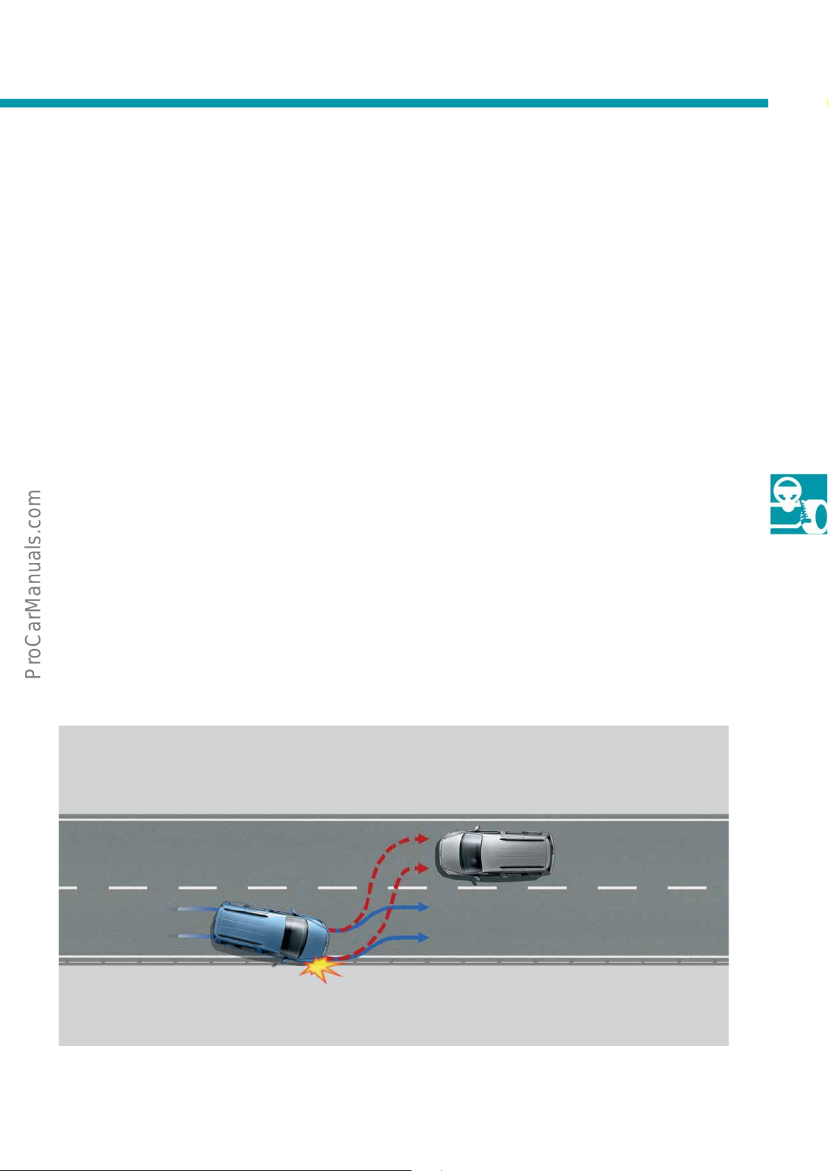
About 22 % of all accidents involving personal injury are multicollisions. Multicollisions are collisions in which the
first impact is followed by further collisions, e.g. with side barriers or oncoming traffic.
Function
The multicollision brake triggers automatic brake
intervention when a first collision is detected. This
automatic braking should prevent follow-on collisions,
or at least reduce the impact energy of a follow-on
collision. The multicollision brake decelerates the
2
vehicle at maximum 6 m/s
activating the emergency brake light and the hazard
warning lights.
The ESP lamp in the instrument cluster informs the
river about the brake intervention. In all cases, the
d
multicollision brake performs braking down to a
vehicle speed of 10 km/h. In this way, the vehicle
can remain under the driver's control even after a
ollision, depending on the accident situation.
c
, at the same time as
To trigger the multicollision brake, the airbag control
uni
t sends a corresponding message to the ABS
control unit. Exclusively the sensors of the airbag
control unit are used for activating the multicollision
brake.
The multicollision brake can be overridden by the
iver at any time. If the driver accelerates or presses
dr
the brake pedal for an even higher deceleration, the
system is overridden.
39
Page 40
Running gear
Fatigue
detected.
Please take a
break.
S560_134
The Driver Alert System (DAS)
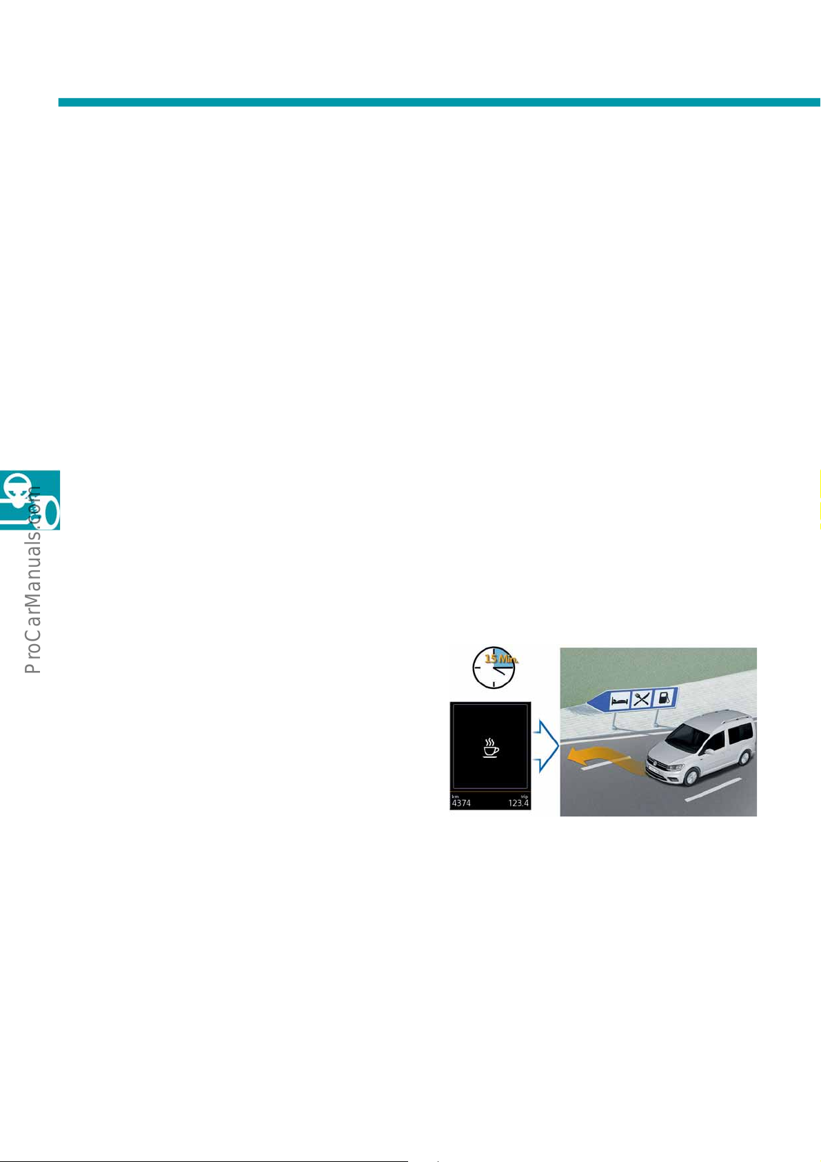
Between and 5 and 25 % of all accidents are caused by fatigue. Driving when fatigued is a cause of more severe
accidents than other accident causes.
The driver alert system (DAS) is a convenience function that supports the driver and has a preventative effect by
etecting the driver's fatigue level.
d
Function
Fatigue is detected by evaluating the steering
behaviour. If the system detects that the driver is at
risk of falling asleep, there is an acoustic warning as
well as a text prompt to take a break displayed on the
multifunction display of the dash panel insert.
Operation and display
Operation
Activation and deactivation is via the dash panel
insert. The function is available from a speed of
65 km/h onwards. Following activation, the system
quires about 15 minutes to collect sufficient data on
re
which to draw a conclusion about the driver's fatigue
as driving continues.
In addition to the steering behaviour, data regarding
he driving situation (vehicle speed, accelerator pedal
t
operation, use of turn indicators, time of day, duration
of driving, etc.) and the driver's activity operating the
settings and comfort elements (air conditioning
system, use of telephone, etc.) are recorded and sent
via the CAN data bus to the diagnostic interface for
the data bus where the data is evaluated. The
software is integrated in the gateway.
40
Display
If driver fatigue is detected, a message is displayed in the dash panel insert and a gong sounds for 5 seconds. The
message and gong are repeated if the driver does not take a break within the next 15 minutes. After this repetition
there is no further warning.
Page 41
The area monitoring system (Front Assist)
S560_143
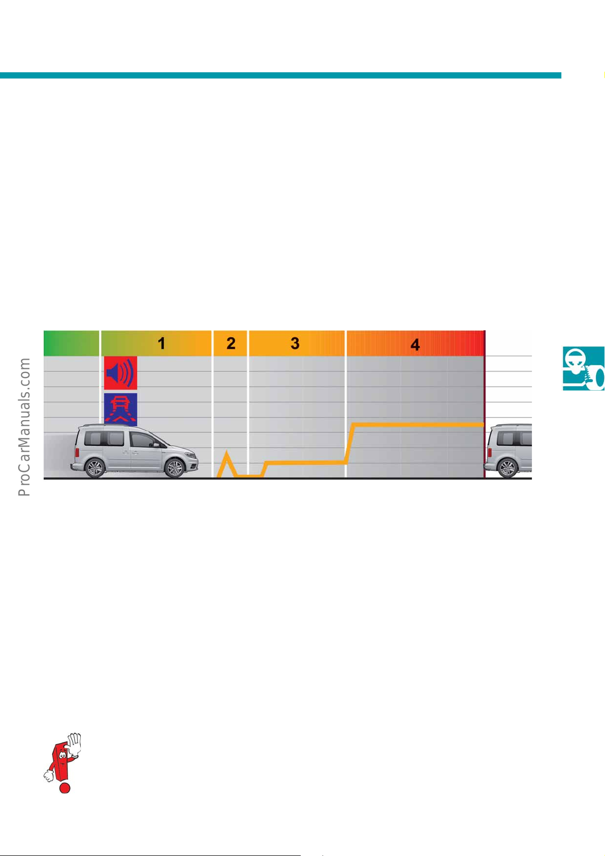
If the risk of a collision is detected, the brake system is
pre-filled. The hydraulic brake assist system is
reduced to a lower triggering threshold and the driver
is given a visual and audible warning. In addition, an
automatic brake jolt alerts the driver to the danger.
If the driver responds with insufficiently powerful
raking, the vehicle automatically generates the
b
brake pressure required by the situation.
At a speed of more than 30 km/h, the automatic
2
celeration is up to 6 m/s
de
If the driver does not respond to the brake jolt either,
ront Assist brakes automatically in order to avoid a
F
collision in the most favourable case, or at least
reduce the severity of the accident.
.
1. Advance warning
• Reduction in stopping distance 1:
- Prefill of the brake, hydraulic
brake assist system threshold changeover
• Reduction in stopping distance 2:
- Visual and audible warning
2. Main warning
• Reduction in stopping distance 1:
Hydraulic brake assist system
Threshold changeover highest level
• Reduction in stopping distance 2:
-Brake jolt
For more information about Front Assist, refer to the Self-Study Programmes no. 470
"The Touareg 2011 – electric/electronic systems" and no. 488 "The Passat 2011".
3. Automatic partial braking
• Reduction in stopping distance 3 (5 – 210 km/h):
Automatic deceleration,
-
2
if the driver does not respond (up to 6 m/s
• Reduction in stopping distance 3 (less than or
equal to 30 km/h):
- Automatic deceleration,
if the driver does not respond (up to 8 m/s
4. Target braking
• Reduction in stopping distance 3:
- Boosting of the driver's braking
to avoid a collision or
reduce the consequences of an accident.
).
2
).
41
Page 42
Running gear
S560_142
S560_144
Automatic emergency braking (AEB)
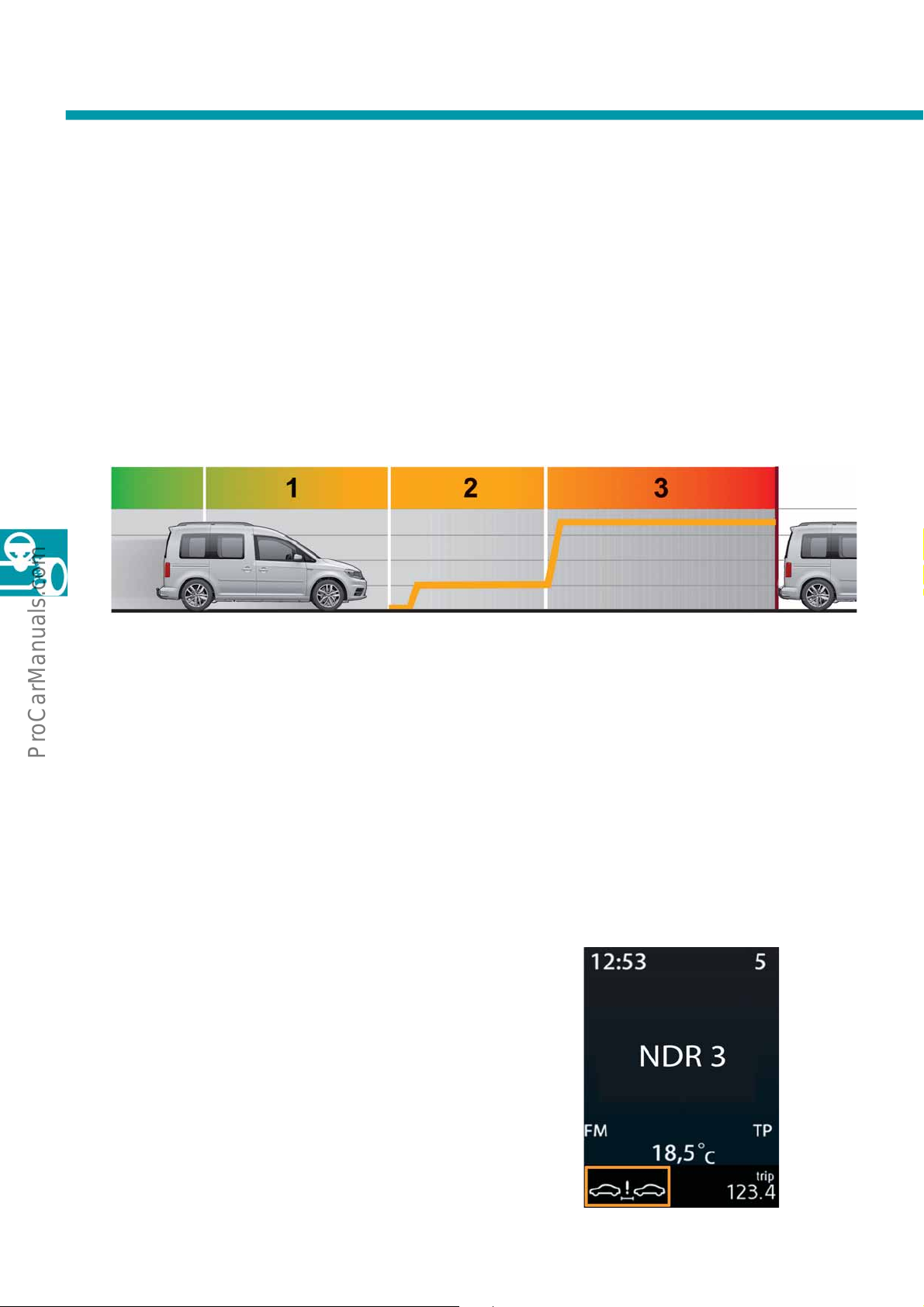
Automatic emergency braking is an expansion to the
Front Assist system, and uses the radar sensor to
monitor the area in front of the vehicle. The system
operates in the speed range below 30 km/h. If the
iver does not respond when there is a risk of a rear-
dr
end collision with a vehicle driving or parked in front,
the brake system is brought to an increased level of
braking readiness, in the same way as with Front
Assist. If required, automatic emergency braking
1. No driver warning
• Reduction in stopping distance 1:
- Prefill of the brake, hydraulic
brake assist system threshold changeover
2. Automatic partial braking
• Reduction in stopping distance 3
ss than or equal to 30 km/h):
(le
- Automatic deceleration,
if the driver does not respond (up to 8 m/s
automatically triggers full braking to a standstill, in
order to reduce the accident severity. The system
provides support by applying maximum braking
effort if the driver does not press the pedal firmly
enough. Like all of these systems, automatic
emergency braking cannot release the driver from
his/her responsibility for driving the vehicle, and thus
cannot be guaranteed to prevent an accident from
occurring.
3. Target braking
• Reduction in stopping distance 3:
Boosting of the driver's braking
to avoid a collision or
reduce the consequences of an accident.
2
).
42
The proximity alarm
The proximity alarm gives the driver a visual
notification if the distance from the vehicle in front is
critical (less than 0.9 s). The proximity alarm function
ses the radar sensor behind the Volkswagen badge
u
measure the distance to the vehicle driving in front.
to
If the system detects that there is a safety risk, the
driver is warned by a corresponding display.
The proximity alarm is active in the speed range from
0 – 210 km/h.
7
Page 43
Heating and air conditioning
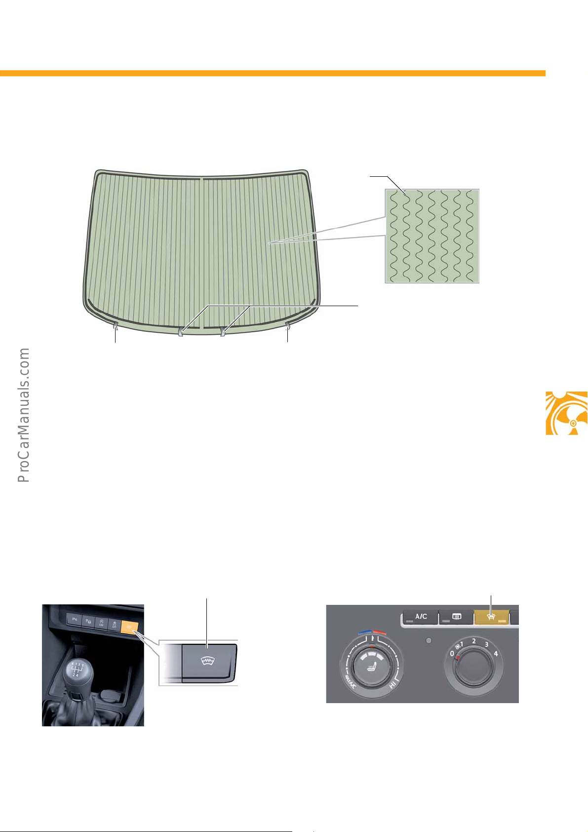
Earth connections
Connection of right heating panel
Connection of left heating panel
Heating wires
S560_091
Windscreen heating switch E180
in the switch module on the centre console
S560_153
Windscreen heating switch E180
in the air conditioning control unit
S560_092
The heated windscreen Z2
The heated windscreen helps with de-icing the windscreen and only functions when the engine is running.
Switching on/off
Windscreen heating switch E180 is located in the control unit of the air conditioning system or the Climatronic or is
located in the switch module in the centre console, depending on which variant is fitted. A CAN message is sent to
the onboard supply control unit to switch the heated windscreen on and off. This then controls the relay of the
heated windscreen. Intervention by the energy management is possible. The windscreen heating remains switched
on for about 4 minutes. It can be switched off early by pressing the switch again.
The windscreen heating is switched off when the engine is stopped.
43
Page 44
Heating and air conditioning
S560_028
321
654
S560_029
5
6
4
892
1
7
3
Air conditioning
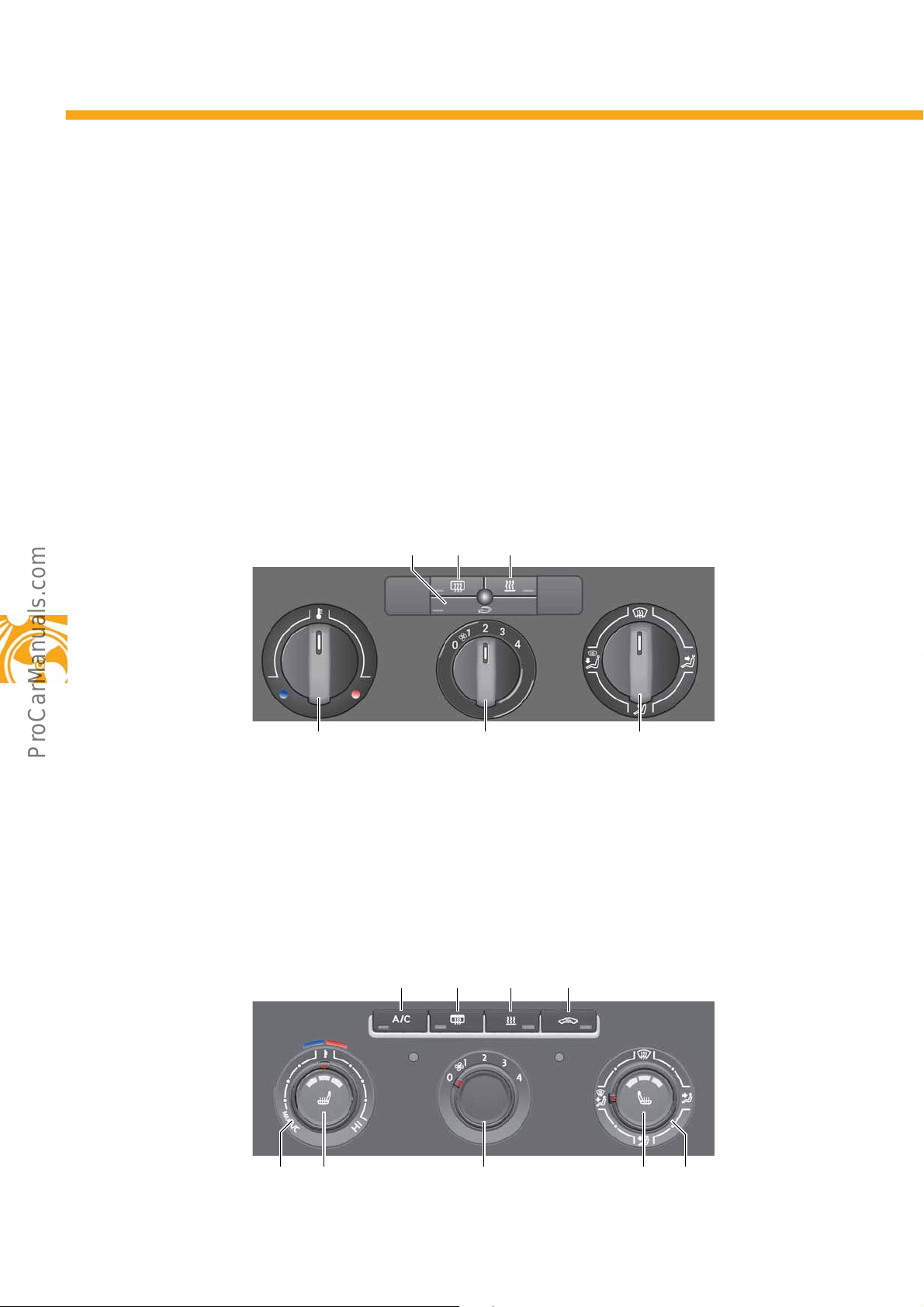
In addition to the manual heating and ventilation system, the Caddy 2016 is also available with an air conditioning
system. 2 versions of the air conditioning system are used:
• Air conditioning system
•
Fully automatic 2-zone Climatronic
Controls
Heating and ventilation system
The heating and ventilation system operates manually using Bowden cables. The temperature flap and air flaps
are adjusted mechanically. The fresh air blower has 5 stages.
Air conditioning system
The climate control system operates manually/electrically. The temperature flap and air flaps are adjusted using
control motors.
All settings are made manually and adjusted manually if required. Like in the heating and ventilation system, the
esh air blower has 4 stages.
fr
44
Page 45
2-zone Climatronic
S560_030
3
4
9
5
11
10
12
2
13
14815
16
7
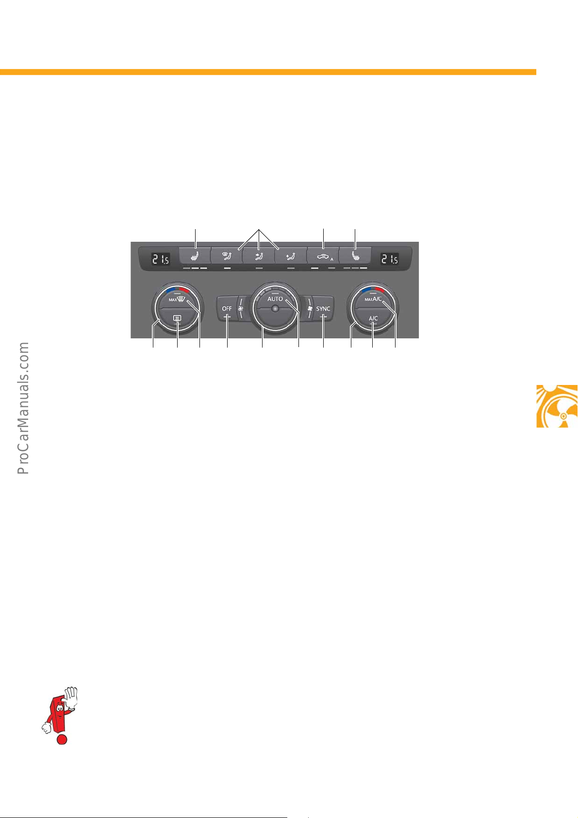
In this climate control system, different temperatures can be set on the driver and front passenger sides, depending
on requirements. The blower stages and flap position are controlled fully automatically, as is the control of the air
blowing out of the nozzles and the interior temperature.
Key to the figures
Blower speed
2
Air distribution
3
Air recirculation mode
4
Rear window heating
5
Immediate heat button of the auxiliary heater
6
Air conditioning system operation
7
Seat heating left
8
Seat heating right
9
Temperature left
10
Temperature
1
Depending on the engine load or the load on the electrical system, the power of the air conditioning
system/Climatronic can be reduced or switched off.
Defrost, defined blower setting and air distribution
11
to
wards the windows
Air conditioning system and blower switched off
12
Automatic control of the blower, temperature and air
13
distribution depending on the sunshine intensity,
outside and inside temperatures
Synchronisation of the climate zones to the driver's
14
value
Temperature right
15
Temperature setting to "LO", maximum blower
16
output, air distribution to the nozzles
45
Page 46

Electrical system
a
The networking concept
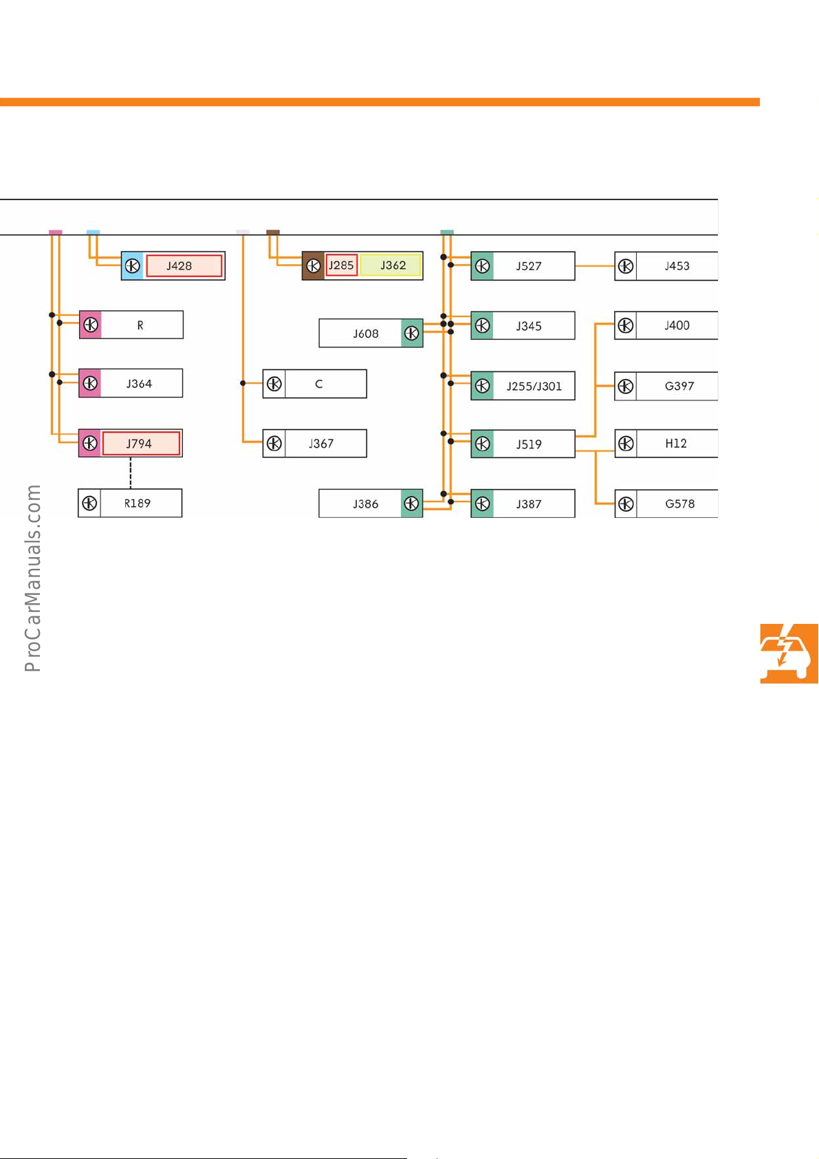
The overview shows all control units that can be
connected to the bus systems. Some of the control
units shown here are optional or vehicle-specific
equipment.
Legend
Powertrain CAN bus
Convenience CAN bus
CAN bus extended
LIN bus
Infotainment CAN bus
Dash panel insert CAN bus
CAN bus line
LIN bus line
Immobiliser participant
Component protection participant
a CAN bus diagnosis
b FBAS (colour image muting signal)
46
Page 47
S560_053
b
C Three-phase generator
E313 Selector lever
G85 Steering angle sender
G397 Sensor for rain and light detection
G578 Anti-theft alarm sensor
H12 Alarm horn
J104 ABS control unit
J234 Airbag control unit
J255 Climatronic control unit
J285 Control unit in dash panel insert
J301 Air conditioning control unit
J345 Trailer detection control unit
J362 Immobilizer control unit
J364 Auxiliary heater control unit
J367 Battery monitor control unit
J386 Driver side door control unit
J387 Front passenger side door control unit
J400 Wiper motor control unit
J428 Control unit for distance control
J446 Control unit for park distance control
J453 Control unit for multifunction steering wheel, in
steering wheel
J492 Four-wheel drive control unit
J500 Power steering control unit
J519 Vehicle electrical system control unit
J527 Steering column electronics control unit
J533 Data bus diagnostic interface
J608 Control unit for special vehicles
J623 Engine control unit
J743 Mechatronic unit for dual clutch gearbox
J791 Park Assist control unit
J794 Control unit 1 for information electronics
J844 Control unit for main beam assist
RRadio
R189 Reversing camera
47
Page 48
Electrical system
S560_034
S560_035
S560_056
Natural gas
gauge G411
Fuel gauge G1
Warning light for natural
gas mode K192
Warning light for fuel
reserve K105
The dash panel insert
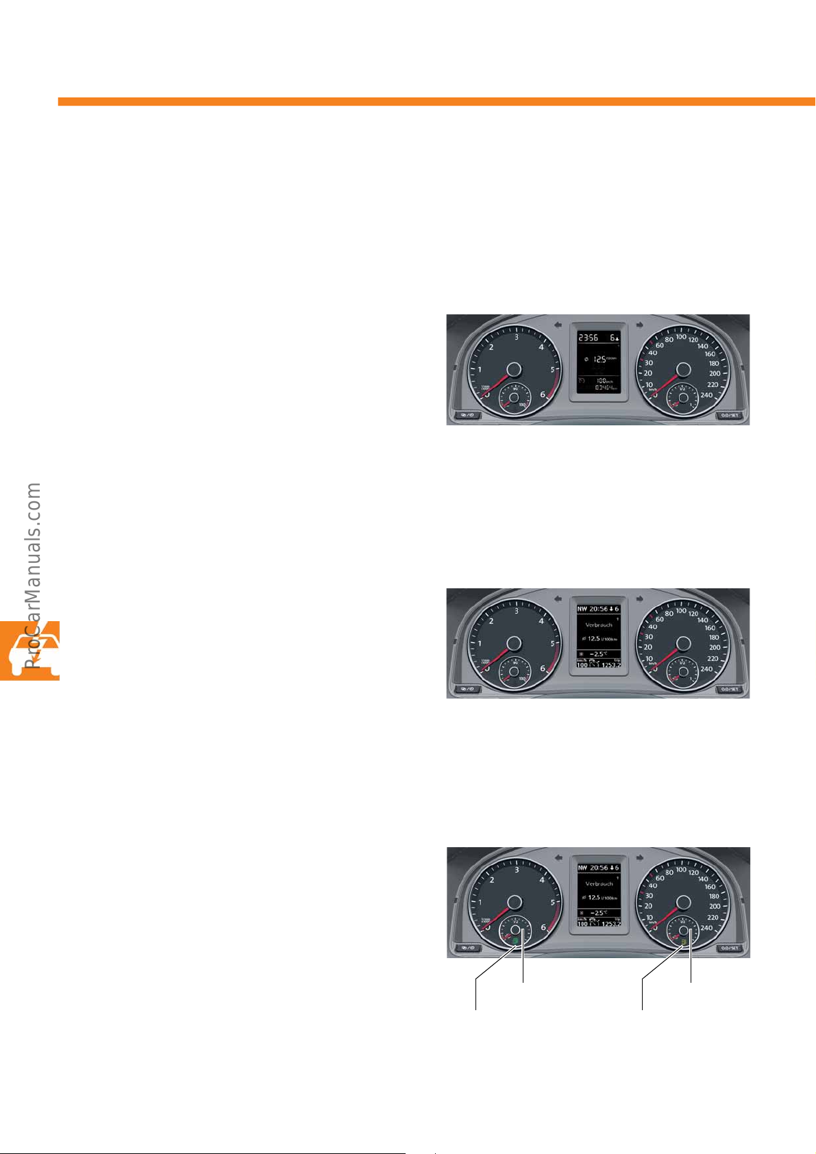
A new generation of dash panel inserts is fitted in the Caddy 2016. These contain the immobiliser control unit
J362. In addition to the displayed variants, there is also a variant without multifunction display (MFD) available.
With MFD
This variant has a black/white segment display with a
maximum of 240 display segments.
A loudspeaker for outputting warning signals is
egrated. The time can be set or the trip recorder
int
reset using adjustment buttons.
With MFD Plus
This variant has a black/white TFT display as MFD,
with a dot matrix of 110 x166 pixels.
Compared to the instrument cluster with MFD, it has
advanced display possibility as a precondition for
an
fitting various equipment items such as driver assist
systems.
Vehicles with natural gas engine
In this variant, there are displays and warning lights
for natural gas and petrol operation. In this case, the
coolant temperature gauge is replaced by the natural
gas tank gauge.
48
Page 49
The multifunction steering wheel
S560_037
S560_038
S560_039
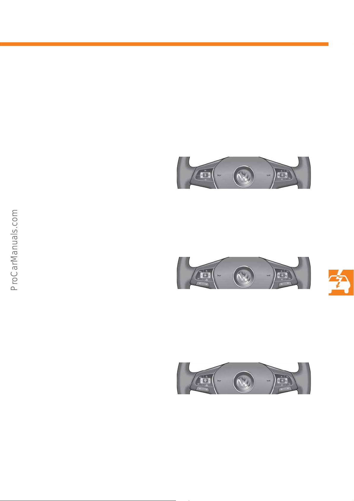
Depending on the equipment variant of the vehicle, the optionally available multifunction steering wheel is available in three variants for the market launch of the Caddy 2016. If no multifunction steering wheel is fitted in the
ehicle, the available functions are operated using buttons on the left and right steering column levers.
v
Depending on the equipment an engine, the buttons and switches for operating the cruise control system (CCS) and
speed limiter may be fitted in the turn indicator and main beam levers.
the
Variant 1
This variant has the controls for the MFD, audio and
telephone. The left-hand steering wheel spoke carries
the control buttons for controlling the audio output,
while the right-hand spoke carries the buttons for
controlling the MFD in the dash panel insert and the
telephone. If this multifunction steering wheel is fitted,
the corresponding buttons are not fitted on the
steering column lever for the MFD operation.
Variant 2
This variant has the controls for MFD, audio,
telephone, cruise control or speed limiter. The lefthand steering wheel spoke carries the control buttons
for controlling the cruise control system, while the
right-hand spoke carries the buttons for controlling
the MFD in the dash panel insert and the telephone.
Audio output is controlled using the buttons recessed
downwards on both steering wheel spokes.
Variant 3
In this variant, the controls for MFD, audio, telephone,
cruise control system or speed limiter and ACC are
included. The left-hand steering column spoke carries
the operating buttons for controlling the cruise control
and ACC. Changing over between the two driver assist
systems is performed using the MODE button. The
right-hand steering wheel spoke carries the operating
buttons for controlling the MFD in the dash panel
insert and the telephone. Audio output is controlled
using the buttons recessed downwards on both
steering wheel spokes.
49
Page 50
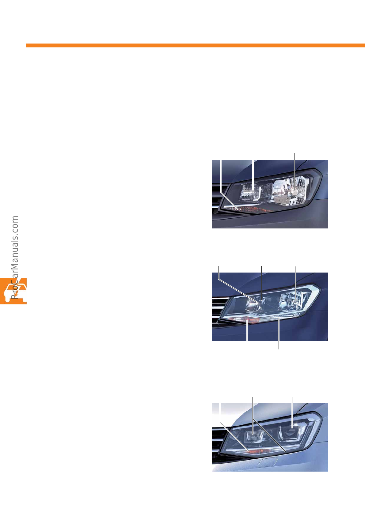
Electrical system
S560_016
Daytime running/
side lights
W, 21/5 W
Turn signal
H, 21 W
Dipped beam/
main beam
H4, 60/55 W
S560_017
Turn signal
H, 21 W
Daytime running
lights H, 21 W
Dipped beam
H7, 55 W
Main beam
H7, 55 W
Side lights
W, 5 W
S560_018
Turn signal
H, 21 W
Daytime running/
side lights LED
Dipped beam/
main beam Xenon
D8S, 25 W, 42 V
The headlights
The exterior design and internal structure of the Caddy 2016 headlight unit has been adapted to the current
design language at Volkswagen Commercial Vehicles. The headlight units have a clear glass structure and are
fitted in the H4, H7 and bi-xenon headlight variants depending on equipment.
Headlight module H4
This headlight module has an H4 bulb for the dipped
and main beams.
As standard, the headlights are equipped with a
aytime running light.
d
Headlight module H7
This headlight module has one H7 bulb each for the
dipped beam and main beam headlights.
As standard, the headlights are equipped with a
aytime running light.
d
Headlight module bi-xenon
A D8S 25 W xenon bulb is used for the dipped and
main beams. The luminous flux is less than
2000 lumen. Headlight washer system and automatic
ght range control are thus not required. The
headli
headlight range is set using the headlight range
control (potentiometer) in the dashboard, like with
halogen headlights.
50
Page 51
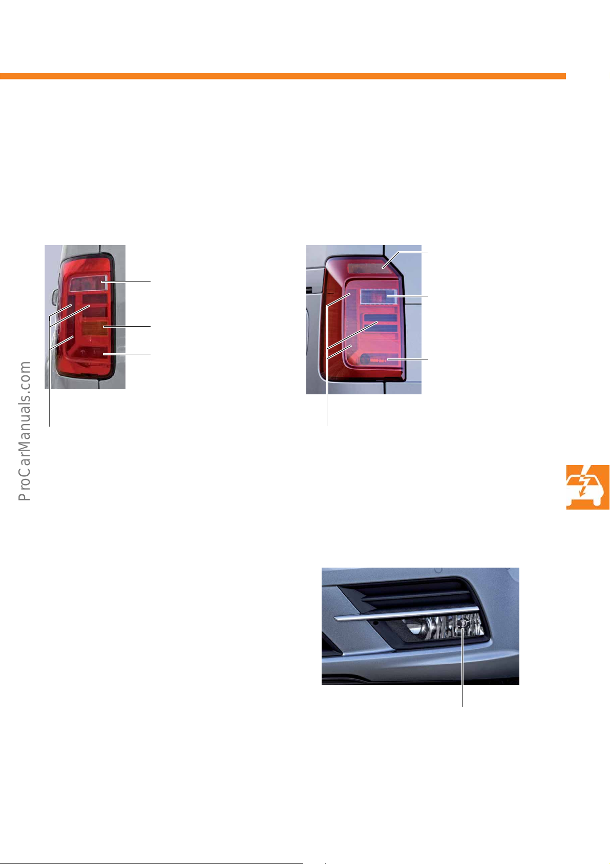
The tail light clusters
S560_113
Brake
Tail light
P, 21 W
Rear fog light or
reversing light
P, 21 W
Turn signal
P, 21 W
Tail light
3x W, 5 W
S560_019
Turn signal
P, 21 W
Rear fog light or
reversing light
P, 21 W
Brake
Tail light
P, 21 W
Tail light
3 x W, 5 W
S560_020
Fog lights/cornering light
H11, 55 W
The tail light cluster is configured as a multi-chamber light. All tail light cluster versions are also available tinted as
an option.
Vehicles with wing doors
Vehicle with tailgate
Fog lights/cornering light
The fog lights are each equipped with one H11-55 W
bulb. As an option, fog lights with static cornering
light can be fitted.
If a static cornering light is fitted, the fog light on the
side of the corner is switched on depending on the
in
speed, up to 40 km/h, and if the lighting system is
witched on and the steering wheel is turned or a turn
s
signal is activated. This provides better illumination of
the edge of the road on the inside of the corner.
51
Page 52
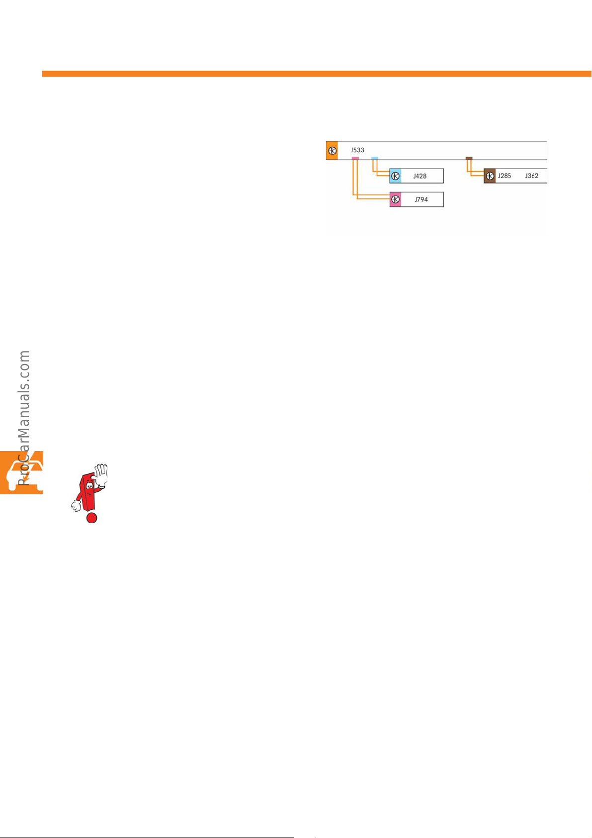
Electrical system
S560_110
The component protection
The Caddy 2016 has component protection for
various control units. This is intended to prevent an
unauthorised exchange of components. The control
unit in the dash panel insert J285 is the master for
compone
In addition to the stated control unit, the control unit
or distance control J428 and the control unit 1 for
f
inf
compone
The participants in the component protection are
check
omparison result is negative, the corresponding
c
component blocks its function partially or entirely and
stores this in the event memory. The component
protection function must then be enabled online with
the vehicle diagnostic tester.
nt protection.
ormation electronics J794 also participate in
nt protection.
ed when terminal 15 is switched on. If the
For more information about component protection, refer to Self-Study Programme ho. 517
"The Golf 2013 electrics".
52
Page 53
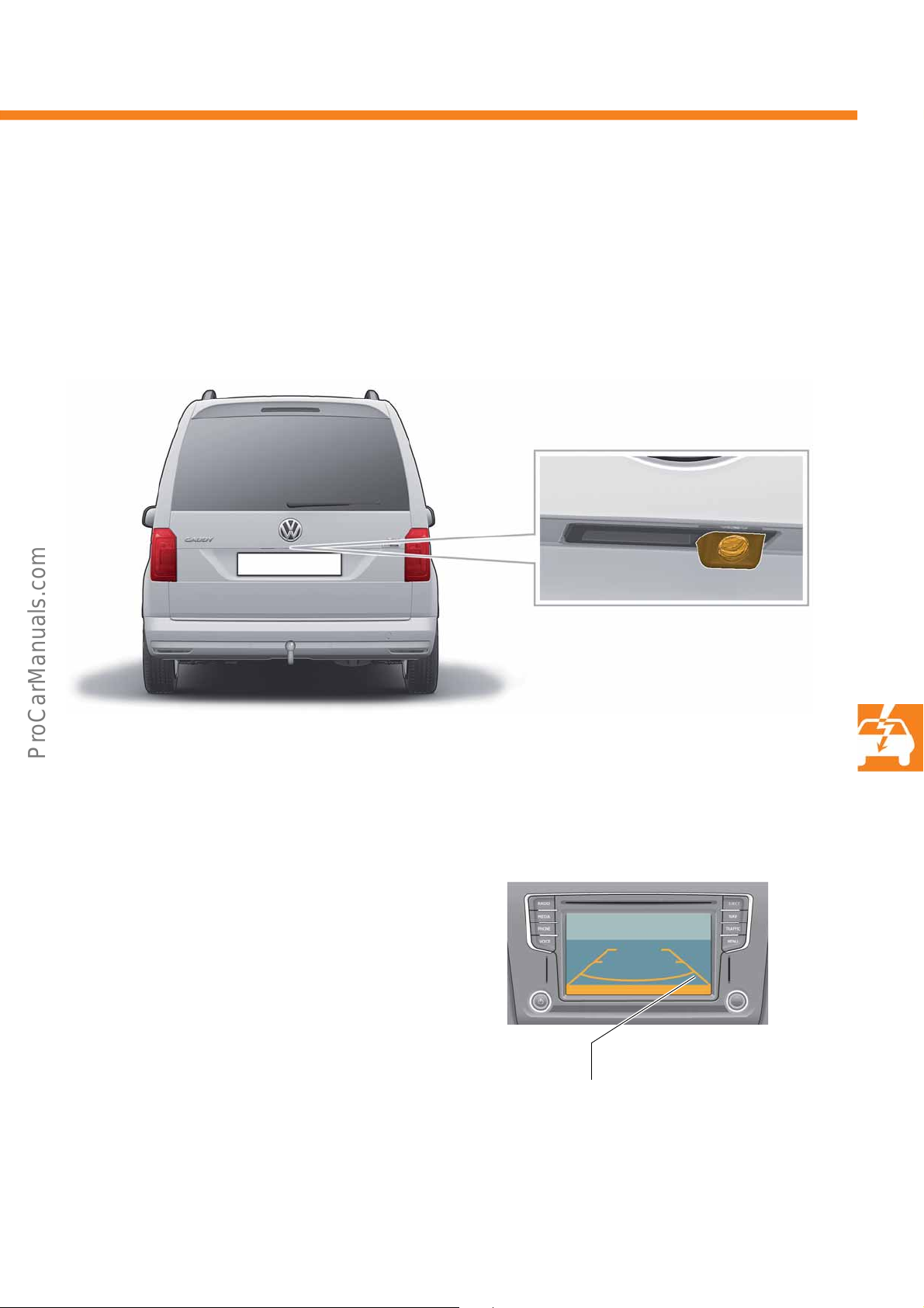
The reversing camera R189
S560_058
Reversing camera R189
S560_067
Static lines
Discover Media display example
The reversing camera R189 is used in the Caddy 2016, and improves visibility to the rear when reversing. It is
attached to the tailgate above the number plate, and supplies a real video image of the area behind the vehicle.
The reversing camera can be combined with the Composition Colour, Composition Media and Discover Media.
Radio display
When terminal 15 is on and reverse gear engaged,
the video signal from the camera is shown on the
screen.
The screen shows the real video image. The static help
nes that overlay the surrounding picture in the colour
li
display are applied by the screen and are used for
gauging distances better. The reversing camera R189
does not require calibration.
53
Page 54
Radio, telephone and navigation
S560_140
S560_141
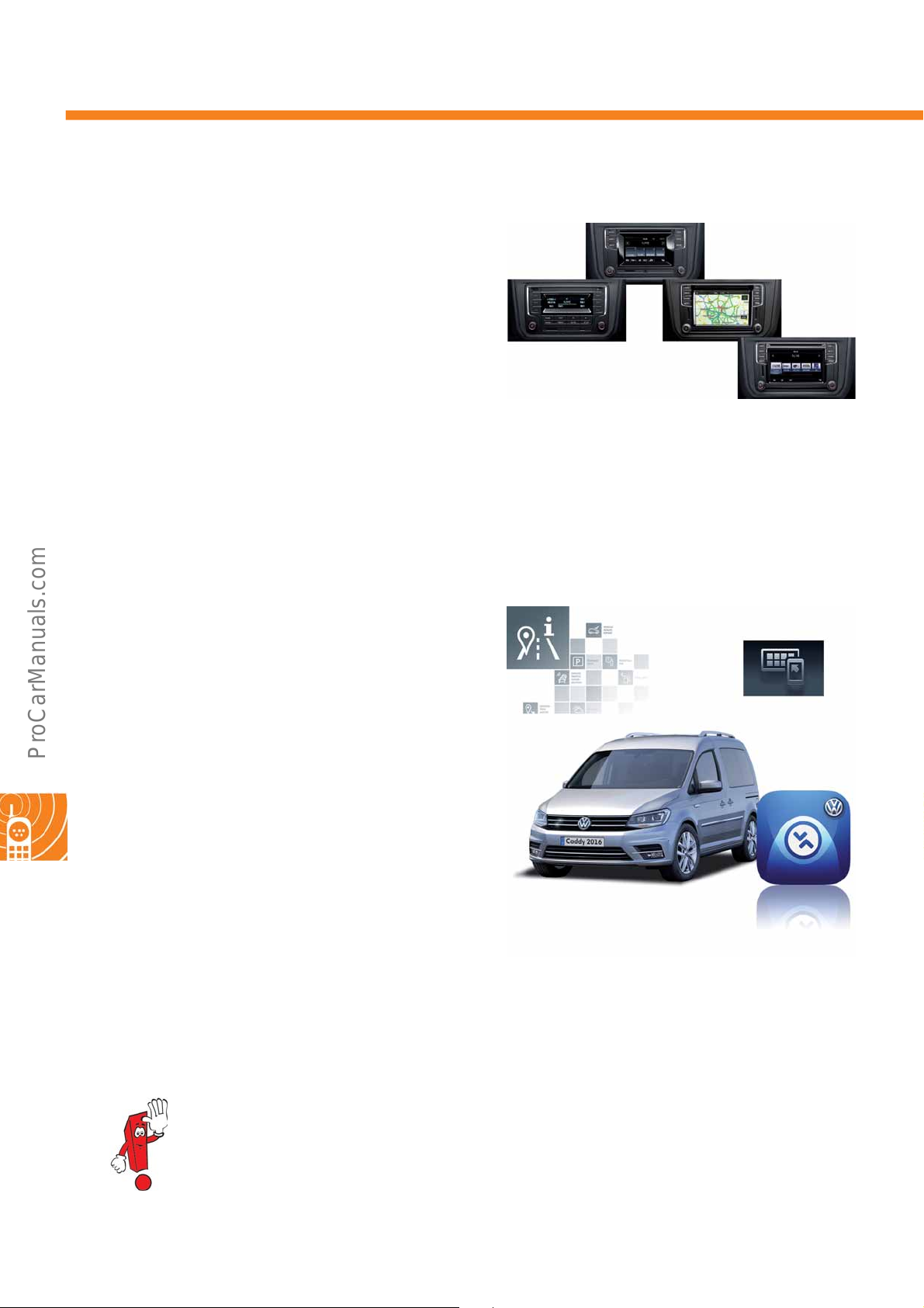
The radios and navigation systems
A new generation of radios and navigation systems is
launching in the Caddy 2016 and T6 2016 for
olkswagen Commercial Vehicles. They set new
V
standards in terms of operation and connection
possibilities for external devices. All devices can be
combined with a provision for mobile telephone.
The following devices are available:
• Composition Audio radio
•Composition Colour radio
• Composition Media radio
• Discover Media navigation system
The Car-Net
For the first time, Volkswagen Commercial Vehicles is
presenting mobile online services, also referred to as
Car-Net. This involves using online data for certain
applications, which are referred to as services. These
can be provided for various application areas.
The following services are currently available:
• Guide & Inform (improved navigation and
infotainment)
• App Connect (smartphone connections and apps)
• Media Control (infotainment expansions via app)
54
For more information about the radios and navigation systems as well as Car-Net, refer to Self-Study
Programme no. 562 "Infotainment and Car-Net in T6 2016 and Caddy 2016".
Page 55

Notes
55
Page 56
560
560
© VOLKSWAGEN AG, Wolfsburg
All rights reserved. Subject to technical modifications.
000.2813.17.20 Technical status 07/2015
Volkswagen AG
Volkswagen Commercial Vehicles, After Sales
After Sales Technology NV-K/K
Brieffach 2940
D-30405 Hannover
❀ This paper was manufactured using pulp bleached without the use of chlorine.
 Loading...