


Free Download Manual ManualsBooks.com
Service Manual
Model S 962-2

Free Download Manual ManualsBooks.com
Hyperlinks
Hyperlinks are cross-references in the text. They are marked with the symbol. The entries in the Table of contents also have hyperlink functionality.
•Clicking takes you to the relevant page.
•Clicking  in the Acrobat navigation bar takes you back to the start page.
Full-text search for a term
•Clicking  opens the "Search" window.
You can search for any term in this Acrobat document or optionally search all of the Acrobat files stored on your computer or those that are accessible.
Other interactive functions
The Adobe Reader and all Adobe Acrobat program versions offer the experienced user a whole range of highly useful functions for interactive working with documents. For more information, see the relevant user manuals or online help.
|
Display table of contents |
Jump to Help page (this page) |
|
||
|
|
|
|
|
|
|
|
|

Version, Imprint, Type label |
Free Download Manual ManualsBooks.com |
Service Manual S33 Version 1.01 (09.08.2012)
for Völker Bed Model S 962-2
from year of construction May 2009
© by Völker GmbH 2010-2012
Völker GmbH
Wullener Feld 79
58454 Witten
GERMANY
Tel.: |
+49 2302 96096-62 |
Fax: |
+49 2302 96096-66 |
E-mail: service@voelker.de
Internet: www.voelker.de
All rights reserved. Reproduction - even in part - is not permitted.
We reserve the right to make changes to reflect technical advances.
The contents of this document are subject to change without prior notification.
Customers are advised to contact the responsible area sales manager before placing an order.
Type label
The type label is located on the inside of the head panel.
Raise the back section to read the type label.
For further information on the type label, see Appendix 162.
Content |
3 of 180 |
Help |
|
|
|
Völker bed model S 962-2 built after May 2009 – Service manual S33 |
V1.01 (09.08.2012) |
Free Download Manual ManualsBooks.com
Help 2 |
Initial startup 27 |
back section 57 |
|
||
Version, Imprint, Type label |
General operating instructions 28 |
|
3 |
Preparation 29 |
|
Table of contents 4 |
Electrical activation 30 |
|
|
Using the battery pack 31 |
|
Notes 7 |
Taking out of service 32 |
|
General information 8 |
|
|
Warning indications 9 |
Lower frame UG4 33 |
|
|
Lower frame 34 |
|
Functional description 11 |
Lifting column long 35 |
|
Overview 12 |
Replacing the spindle cartridge |
|
Hand control with hook 13 |
36 |
|
Transverse hand control (option) 15 |
Lifting head cross-member, head 38 |
|
Nurse keypad 17 |
Lifting head cross-member, foot 39 |
|
with complete lock 18 |
Replacing the lift motor 40 |
|
with individual lock (option) 19 |
Mechanical brake 42 |
|
with individual lock/automatic |
Castor set 43 |
|
functions (option) 20 |
Replacing the castor 44 |
|
with individual lock/automatic/ |
|
|
lower leg section functions (option) |
Frame 45 |
|
21 |
Frame 46 |
|
Trapeze bar and accessory holders, |
Panel set 47 |
|
accessory rail 22 |
Head panel 51 |
|
Versions and options 23 |
Foot panel 53 |
|
Accessories 25 |
CPR 55 |
|
|
Motor frame fitting set 56 |
|
|
Motor frame fitting, |
|

Table of contents 1/3
Motor frame fitting, upper leg section 58
Fasteners DA01 59 Dynamic bed extension (option) 60
Foot section extension (option) 64
Lying surface 66
Lying surface frame
67 Back section
68
Upper leg/Seat section 70 Lower leg section 72 Hydrolift adjustment 76
MiS lying surface 77 Back section 78 Seat section 79 Upper leg section 80 Lower leg section 81
HPL lying surface (variant) 83 Back section 84 Seat section 85 Upper leg section
Content
Free Download Manual ManualsBooks.com
86 Lower leg section 87
5 of 180 |
Help |
Völker bed model S 962-2 built after May 2009 – Service manual S33 |
V1.01 (09.08.2012) |
Free Download Manual ManualsBooks.com
Side rails from year of construction 03/2010 89 |
Mattress holder, lower leg section |
Bed linen storage area to year of |
Side rail set 90 |
117 |
construction 03/2010 134 |
Back section 91 |
Clamp 118 |
|
Lower leg section 92 |
|
Electronics 135 |
Mattress holder, back section 94 |
Bumper set 119 |
Electronic dual drive DA01 |
Mattress holder, lower leg section |
Bumper set 120 |
136 |
95 |
Bumper set 121 |
Variants 137 |
Side rail set (raised) 96 |
Replacing the bumpers 122 |
Spare parts 138 |
Back section 98 |
|
Replacing the dual drive DA01 |
Lower leg section 99 |
Head and foot section 123 |
139 |
Mattress holder,back section 101 |
Head and foot section design variant S |
Replacing the battery pack 141 |
Mattress holder, lower leg section |
124 |
Hand control and nurse keypads |
102 |
Aluminium corner tube 126 |
142 |
Clamp 103 |
HeadandfootsectiondesignvariantMA |
|
|
(variant) 127 |
Maintenance 143 |
Side rails to year of construction 02/2010 104 |
HeadandfootsectiondesignvariantMB |
Staff training 144 |
Side rail set 105 |
(variant) 128 |
Safety notes 145 |
Back section 106 |
|
Maintenance schedule 146 |
Lower leg section 107 |
Bed linen storage area 129 |
|
Mattress holder, back section |
Bed linen storage area from year of |
Technical check 147 |
109 |
construction 04/2010 130 |
Visual inspection 148 |
Mattress holder, lower leg section |
Bed linen storage area |
Functional check of the side rails |
110 |
from year of construction 03/2011 131 |
148 |
Side rail set (raised) 111 |
Guide 132 |
Functional check of the brakes 150 |
Back section 113 |
Bed linen storage area |
Functional check of the motors |
Lower leg section 114 |
from year of construction 04/2010 - |
150 |
Mattress holder, back section 116 |
02/2011 133 |
Mains connection cable 150 |

Table of contents 3/3
Cabling 150
Housing 150 Mechanical check 150
Measuring in accordance with DIN EN 62353 (formerly VDE 0751-1) 151 Checking the trapeze bar grab handle 151
Further accessories 151
Troubleshooting 152
Table of faults 153
Appendix 156
Spare part order 157 Tool list 157
Service points 157 Symbols used 158 Technical data 159 Classification 161 Type label 162
Dimension print S 962-2 164 Service life/disposal 165 Manufacturer's declarations, forms, electronic service manual
166
Content
Free Download Manual ManualsBooks.com
7 of 180 |
Help |
Völker bed model S 962-2 built after May 2009 – Service manual S33 |
V1.01 (09.08.2012) |
The Notes section contains general notes and warning notes.
Free Download Manual ManualsBooks.com
CONTENTS
General information 8
Warning indications 9

Notes | General information
General notes
You have purchased a bed from Völker AG. This bed has been built in accordance with the applicable national and international standards and the regulations reflecting the current state of technology.
Völker beds satisfy requirements in terms of safety and functionality. They are tested in accordance with international standards and bear the CE mark, which documents the beds' compliance with essential requirements for medical products.
However, please read the fundamental safety provisions (see also instructions for use). Please also note (with particular attention to any warranty claims) the further notes on the following pages.
This service manual is intended to give service technicians relevant information and ensure they work correctly.
Every person involved with maintenance or servicing must at least
•have taken part in service training by Völker,
•have read the safety notes and
•the service manual
and be qualified in accordance with MPBetreibV sections 4 and 6.
To avoid errors and ensure that our beds work properly, these documents must always be accessible to service personnel. (Please also refer to page 142 in regard to staff training).
Copyright protection
This service manual may only be transferred to third parties with the written consent of Völker GmbH. All documents are protected under copyright.
Warranty and liability
Völker GmbH is liable for any faults or failures, not including further claims arising in the context of the warranty obligations detailed in the main agreement. Claims for compensation, for whatever legal reason such claims may be raised, will not be entertained.
We reserve the right to make technical modifications without notice as part of the further development of the beds which form the subject of this service manual. All specifications are non binding. Printing errors excepted.
We accept no liability for damage and operational faults caused as a result of misuse and/or non-observance of this service manual.
The portrayal of the accessories does not necessarily match the actual product.
Content |
9 of 180 |
Help |
|
|
|
Völker bed model S 962-2 built after May 2009 – Service manual S33 |
V1.01 (09.08.2012) |

Warning symbols Information marked with this symbol must always be read and strictly observed!
DANGER represents an immediate threat of danger that can cause serious physical injury or death.
WARNING represents potentially dangerous situations that can lead to serious physical injury or death.
CAUTION represents potentially dangerous situations that can cause slight physical injuries.
NOTE warns of potential damage to objects or property.
Free Download Manual ManualsBooks.com
Before commencing maintenance work
The service manual must be read in full by the person responsible for carrying out the servicing before starting the work.
Before commencing maintenance or repair work, the personnel responsible must be familiarised in detail with how to handle the bed and their attention must be drawn to the individual hazards described in this manual during assembly and disassembly of the bed's components.
The bed is not protected against explosion and must therefore only be serviced in an environment free from flammable substances and materials.
WARNING Before carrying out repair work, always pull out the mains plug and disconnect the bed from the battery pack by pressing the green reset button on the dual drive!
WARNING Maintenance and repair work should only be carried out after the bed has been disinfected.
WARNING Maintenance and repair work should only be carried out on an unoccupied bed. The patient may also have to be transferred to another bed before the work.
General regulations
The bed must only be operated and used in accordance with its designated purpose, in line with the conditions of the Medical Products Directive (MPG) and approved legislation pursuant to this, the generally-acknowledged rules of technology and the stipulations
of occupational safety and accident protection guidelines. The bed may not be operated in a faulty state that could endanger the patient, care staff or third parties.
Notes | Warning indications 2/2
Before first activation
Before the bed is activated for the first time, care personnel must be instructed in the handling of the bed using the instructions for use. The potential dangers that can arise despite correct operation of the bed must also be pointed out in full.
Transporting the bed
CAUTION When moving the bed, it must always be ensured that the mains connection cable does not touch the ground.
The bed should only be moved on a solid floor. Never attempt to push it over obstacles of over 2 cm in height. The maximum angle of inclination of the floor must not exceed 10°.
Cleaning and disinfection
In order to maintain consistent functioning, the bed should be cleaned, disinfected and tested as soon as possible following each use, so that it can be reused immediately without risk.
Incorrect cleaning/disinfection of the bed can cause danger.
Maintenance and repair
Anyone responsible for carrying out maintenance and repair work must at least have received service training from Völker, have read the safety notes and the service manual and be qualified in accordance with MPBetreibV sections 4 and 6.
After maintenance work or repairs have been carried out, a technical check
145 must be carried out on the affected parts and/or functions. During this check, it must be determined that the bed can be used in accordance with the specifications without risk to patients, users or third parties.
The technical check 145 must be carried out at least once a year and after every lengthy period of non-use.
Any discernible damage, such as signs of wear and tear, loose screws or breaks/fractures must be eliminated immediately.
Electromagnetic and electrostatic faults
The beds in model series S 962-2 satisfy the EMC requirements in accordance with the law on medical products (MPG). The basis for testing is standard EN 60601-1-2.
Content |
11 of 180 |
Help |
|
|
|
Völker bed model S 962-2 built after May 2009 – Service manual S33 |
V1.01 (09.08.2012) |
The features of the Völker care bed and its function are set out in the section Functional description.
Free Download Manual ManualsBooks.com
CONTENTS
Overview 12
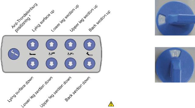
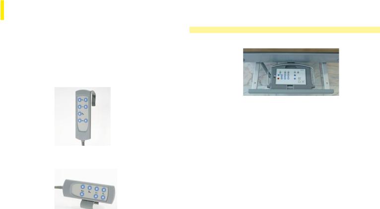
Hand control with hook 13
Transverse hand control (option) 15
Nurse keypad 17
with complete lock 18
with individual lock (option) 19 with individual lock/automatic functions (option) 20
with individual lock/automatic/ lower leg section functions (option) 21
Trapeze bar and accessory holders, accessory rail 22
Versions and options 23
Accessories 25

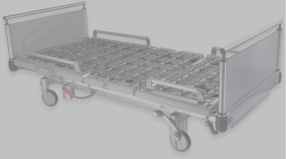
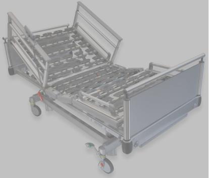
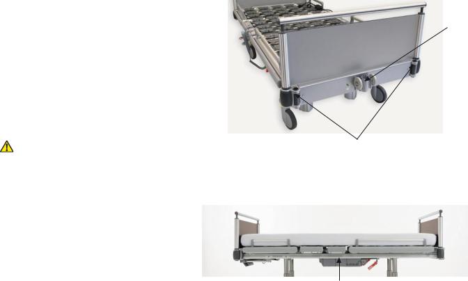
Functional description | Overview
Head section (Quick release, see Fig. on right)
Hand control
Trapeze bar holder on frame (concealed by head section)
Accessory holder,  on both sides,
head and foot end (concealed by head section)
Seat section, fixed
CPR adjustment (mechanical quick release of the back section for cardiopulmonary resuscitation)
Adjustable upper leg section
Adjustable |
Adjustable side rails |
back section |
for back section, both sides |
Accessory rail for holding accessories (urine bottle basket, universal hook, etc.) on both sides
Double foot pedal, both sides
Content |
13 of 180 |
Adjustable lower leg section
Foot section (Quick release, see Fig. on right)
Nurse keypad in bed linen storage area, can be pulled out
Adjustable side rails for lower leg section, both sides
4-column height adjustment
Help
Völker bed model S 962-2 built after May 2009 – Service manual S33 |
V1.01 (09.08.2012) |
Free Download Manual ManualsBooks.com
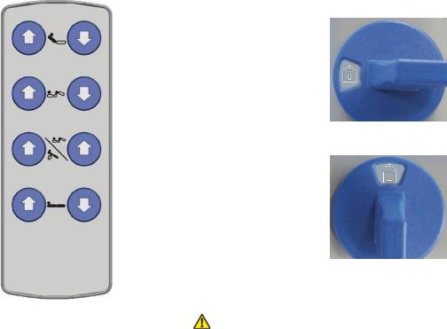
Back section up |
Back section down |
|
Upper leg section up |
Upper leg section down |
Hand control |
|
|
|
|
|
locked |
Anti-Trendelenburg |
Auto-Contour 2 |
|
positioning 1 |
(optional) |
|
Lying surface up |
Lying surface down |
|
|
|
Hand control |
|
|
unlocked |
1Head end raised
2Back and upper leg section raised simultaneously
WARNING When actuating motorised adjustments with the side rails raised, it must be ensured that nobody has any contact with the side rails, and that no body parts are sticking through the side rails or are trapped between the lying surface and the lower frame and/or floor!
|
Free Download Manual ManualsBooks.com |
|
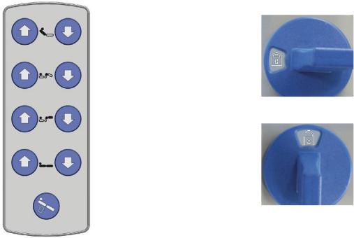
Back section up |
Back section down |
|
Upper leg section up |
Upper leg section down |
Hand control |
|
|
|
|
|
locked |
Lower leg section up |
Lower leg section down |
|
Lying surface up |
Lying surface down |
|
|
|
Hand control |
Anti-Trendelenburg |
|
unlocked |
positioning 1 |
|
|
WARNING When actuating motorised adjustments with the side rails raised, it must be ensured that nobody has any contact with the side rails, and that no body parts are sticking through the side rails or are trapped between the lying

Functional description | Transverse hand control (option) 1/2
1Back and upper leg section raised simultaneously
2Head end raised
Content
Reverse:
Hand control locked
Hand control unlocked
WARNING When actuating motorised adjustments with the side rails raised, it must be ensured that nobody has any contact with the side rails, and that no body parts are sticking through the side rails or are trapped between the lying surface and the lower frame and/or floor!
15 of 180 |
Help |
Völker bed model S 962-2 built after May 2009 – Service manual S33 |
V1.01 (09.08.2012) |
Free Download Manual ManualsBooks.com
Hand control locked
Hand control unlocked
|
WARNING When actuating motorised adjustments with the |
|
side rails raised, it must be ensured that nobody has any |
|
contact with the side rails, and that no body parts are stick- |
|
ing through the side rails or are trapped between the lying |
1 Head end raised |
surface and the lower frame and/or floor! |
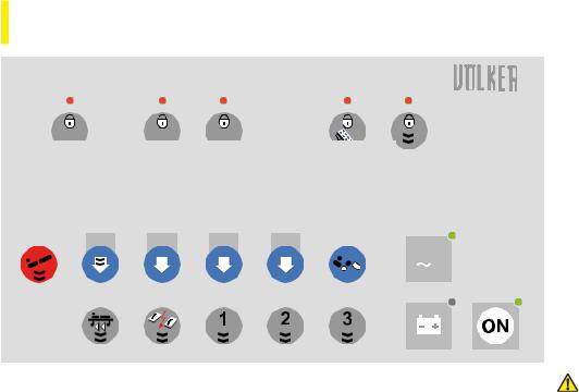
Functional description | Nurse keypad 1/5
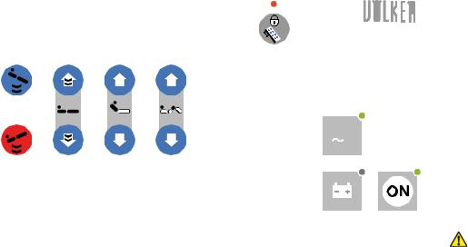
NOTE Please note that to operate the bed, the nurse keypad must be switched on by pressing the on switch.
If no electric function can be activated, press the green reset button on the dual drive. Then press the green button on the mains isolation after 10 seconds in order to reactivate the bed.
Never press both green buttons at the same time.
NOTE The mains voltage is connected for the duration of the active time of the nurse keypad (120 sec.), so that the LED of the mains voltage display also lights up whenever the nurse keypad is active. If the keypad switches over to the inactive state, the mains power is switched off.
Double-click function
The nurse keypad can be equipped with an automatic function (doubleclick) on a country-by-country basis. Keys that can be assigned this function are marked with a double black arrow
symbol  .
.
With a double-click on the "Lying surface up" or "Lying surface down" button, for example, the lying surface moves to the highest or lowest position, respectively. This function can be stopped at any time by pressing any button (except the "ON" switch).
Content |
17 of 180 |
The automatic function can be deactivated by pressing the "Lock auto-
matic function"  key. If the function is locked, the LED above the key will light up red. If the double click function is permanently locked by at the factory, the LED will always light up red when the nurse keypad is switched on.
DANGER "Risk of entrapment between the lower frame or floor and the bed frame when the bed is being lowered"
It must be ensured that: no people, limbs, pets,
bed linen or other objects are trapped between the bed frame and lower frame or floor during adjustment manoeuvres.
CAUTION The functions
-Automatic washing system position
-Manual washing
-Bed preparation
are purely service functions and may only be executed if the bed is unoccupied.
Help
Völker bed model S 962-2 built after May 2009 – Service manual S33 |
V1.01 (09.08.2012) |
Free Download Manual ManualsBooks.com
|
|
|
|
9 |
|
1 |
3 |
5 |
7 |
|
|
|
|
|
|
10 |
V |
2 |
4 |
6 |
8 |
|
|
|
|
||||
|
|
|
|
11 |
12 |
|
|
|
|
|
|
1 |
Anti-Trendelenburg positioning 1, 6 |
7 |
Upper leg section up |
|
|
2 |
Trendelenburg positioning 2, 6 |
8 |
Upper leg section down |
|
|
3 |
Lying surface up 6 |
|
9 |
Lock hand control |
|
4 |
Lying surface down 6 |
|
10 |
Mains voltage display 3 |
|
5 |
Back section up |
|
11 |
Battery display 4 |
|
6 |
Back section down |
|
12 |
"ON" switch 5 |
|
1Head end raised
2Head end lowered
3Green: mains voltage is on
4Green: >80% charged; yellow: 30-80% charged; red: discharged; flashing: charging
5After pressing the "ON" button, the keypad is available for up to 120 sec. after the last action, then it goes into stand-by mode
6Automatic function with double click possible on a country-by-country basis
WARNING When actuating motorised adjustments with the side rails raised, it must be ensured that nobody has any contact with the side rails, and that no body parts are sticking through the side rails or are trapped between the lying surface and the lower frame
Functional description | Nurse keypad with individual lock (option) 3/5
|
|
|
|
|
|
1 |
Head end raised |
|
|
|
|
|
|
|
|
2 |
Head end lowered |
|
|
|
|
|
|
|
|
|
|
|
|
|
|
|
3 |
Back and upper leg section raised simultaneously |
|
|
|
|
|
|
|
|||
|
|
|
|
|
|
4 |
Green: mains voltage is on |
|
|
|
|
|
|
|
5 |
Green: >80% charged; yellow: 30-80% charged; |
|
|
|
|
|
|
|
|
|
Red: discharged; flashing: charging |
11 |
|
12 |
13 |
14 |
15 |
6 |
After pressing the "ON" button, the keypad is |
|
|
|
|
|
|
|
|
|
available for up to 120 sec. after the last action, |
|
|
|
|
|
|
|
|
then it goes into stand-by mode |
|
|
|
|
|
|
7 |
Automatic function with double click possible on |
|
1 |
3 |
5 |
7 |
9 |
|
|
|
a country-by-country basis |
|
|
|
|
|||||
|
|
|
|
|
16 |
V |
2 |
4 |
6 |
8 |
10 |
|
|
|
|
|||||
|
|
|
|
|
17 |
18 |
1 |
Anti-Trendelenburg positioning 1, 7 |
11 |
Lock lying surface lift and |
2 |
Trendelenburg positioning 2, 7 |
|
Anti-Trendelenburg positioning |
3 |
Lying surface up 7 |
12 |
Lock back section |
4 |
Lying surface down 7 |
13 |
Lock upper leg section |
5 |
Back section up |
14 |
Lock hand control |
6 |
Back section down |
15 |
Lock automatic function |
7 |
Upper leg section up |
16 |
Mains voltage display 4 |
8 |
Upper leg section down |
17 |
Battery display 5 |
9 |
Cardiac chair position 7 |
18 |
"ON" switch 6 |
10 |
Auto-Contour 3 |
|
|
Content |
19 of 180 |
WARNING When actuating motorised adjustments with the side rails raised, it must be ensured that nobody has any contact with the side rails, and that no body parts are sticking through the side rails or are trapped between the lying surface and the lower frame and/or floor!
Help
Völker bed model S 962-2 built after May 2009 – Service manual S33 |
V1.01 (09.08.2012) |
Free Download Manual ManualsBooks.com
|
11 |
12 |
13 |
|
14 |
15 |
|
1 |
3 |
5 |
7 |
|
9 |
|
|
|
|
|
|
|
|
21 |
V |
2 |
4 |
6 |
8 |
|
10 |
|
|
|
|
|
|||||
|
16 |
17 |
18 |
19 |
20 |
22 |
23 |
|
|
|
|
|
|
|
|
1 |
Anti-Trendelenburg positioning 1, 10 |
12 |
Lock back section |
2 |
Trendelenburg positioning 2, 10 |
13 |
Lock upper leg section |
3 |
Lying surface up 10 |
14 |
Lock hand control |
4 |
Lying surface down 10 |
15 |
Lock automatic function |
5 |
Back section up |
16 |
Transport position 10 |
6 |
Back section down |
17 |
Resuscitation position 10 |
7 |
Upper leg section up |
18 |
Automatic washing system position 4, 10 |
8 |
Upper leg section down |
19 |
Manual washing 5, 10 |
9 |
Cardiac chair position 10 |
20 |
Bed preparation 6, 10 |
10 |
Auto-Contour 3 |
21 |
Mains voltage display 7 |
11 |
Lock lying surface lift and |
22 |
Battery display 8 |
|
Anti-Trendelenburg positioning |
23 |
"ON" switch 9 |
1Head end raised
2Head end lowered
3Back and upper leg section raised simultaneously
4Height 80 cm, Anti-Trendelenburg positioning 5°, back section 25°
5Height 80 cm, back and upper leg section max. engaged
6Height 80 cm, back and upper leg section in zero position
7Green: mains voltage is on
8Green: >80% charged; yellow: 30-80% charged; red: discharged; flashing: charging
9After pressing the "ON" button, the keypad is available for up to 120 sec. after the last action, then it goes into stand-by mode
10Automatic function with double click possible on a country-by-country basis
WARNING When actuating motorised adjustments with the side rails raised, it must be ensured that nobody has any contact with the side rails, and that no body parts are sticking through the side rails or are trapped between the lying surface and the lower frame and/or floor!
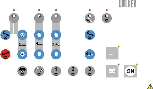
Description of function | Nurse keypad with individual lock/automatic/low leg section functions (option) 5/5
|
13 |
14 |
15 |
|
16 |
17 |
|
1 |
3 |
5 |
7 |
9 |
11 |
|
|
|
|
|
|
|
|
23 |
V |
2 |
4 |
6 |
8 |
10 |
12 |
|
|
|
|
||||||
|
18 |
19 |
20 |
21 |
22 |
24 |
25 |
1Head end raised
2Head end lowered
3Back and upper leg section raised simultaneously
4Height 80 cm, Anti-Trendelenburg positioning 5°, back section 25°
5Height 80 cm, back and leg sections max. engaged
6Height 80 cm, back and leg sections in zero position
7Green: mains voltage is on
8Green: >80% charged; yellow: 30-80% charged;
red: discharged; flashing: charging
9After pressing the "ON" button, the keypad is available for up to 120 sec. after the last action, then it goes into stand-by mode
10Automatic function with double click possible on a country-by-country basis
1 |
Anti-Trendelenburg positioning 1, 10 |
|
Anti-Trendelenburg positioning |
2 |
Trendelenburg positioning 2, 10 |
14 |
Lock back section |
3 |
Lying surface up 10 |
15 |
Lock upper and lower leg sections |
4 |
Lying surface down 10 |
16 |
Lock hand control |
5 |
Back section up |
17 |
Lock automatic function |
6 |
Back section down |
18 |
Transport position 10 |
7 |
Upper leg section up |
19 |
Resuscitation position 10 |
8 |
Upper leg section down |
20 |
Automatic washing system position 4, 10 |
9 |
Lower leg section up |
21 |
Manual washing 5, 10 |
10 |
Lower leg section down |
22 |
Bed preparation 6, 10 |
11 |
Cardiac chair position 10 |
23 |
Mains voltage display 7 |
12 |
Auto-Contour 3 |
24 |
Battery display 8 |
13 |
Lock lying surface lift and |
25 |
"ON" switch 9 |
WARNING When actuating motorised adjustments with the side rails raised, it must be ensured that nobody has any contact with the side rails, and that no body parts are sticking through the side rails or are trapped between the lying surface and the lower frame and/or floor!
Content |
21 of 180 |
Help |
|
|
|
Völker bed model S 962-2 built after May 2009 – Service manual S33 |
V1.01 (09.08.2012) |
Holders for single trapeze bars (only head end) and accessories are located on the outside of the head and foot panels. A double trapeze holder on the inside of the head panel is also optionally available.
The trapeze bar and other accessories must be slotted into the holders until they audibly engage.
The safe working load of the trapeze bar is 75 kg.
WARNING Only original Völker trapeze bars should be used!
Free Download Manual ManualsBooks.com
Trapeze bar holder
Accessory holders (e.g. for drip stands etc.)
There is an accessory rail on either side of the bed to accommodate accessories.
Accessories rail
(e.g. for urine bottle basket, universal hook, etc.)
Functional description | Versions and Options 1/2
The standard design of the bed can be supplied with various versions and options.
Independent of the fastening option, there are optional hand control and nurse keypads with different function keys.
Version/option |
Description |
Hand control |
1. With hook (standard): |
(versions) |
|
2. Transverse on the side rail with clip (option):
Version/option |
Description |
Nurse |
In bed linen storage area: |
keypad |
|
Castors |
The standard design has 150 mm castors. |
|
Different types of castors are available as |
|
an option. The design and the diameter are |
|
variable. This can lead to the a variation in the |
|
lifting adjustment area of around 20 mm. |
Bed extension |
The bed can be extended by 28 cm via a |
(option) |
dynamic bed extension (20 cm on beds |
|
before year of construction 04/2010). |
Content |
23 of 180 |
Help |
|
|
|
Völker bed model S 962-2 built after May 2009 – Service manual S33 |
V1.01 (09.08.2012) |

|
Free Download Manual ManualsBooks.com |
|
|
|
|
Version/option |
Description |
|
Side rails |
The bed (except for design versions MA and |
|
(versions) |
MB) can be equipped with various side rail |
|
|
versions: |
|
Back/lower leg section*:
1.Can be pulled out up to 34* cm (standard)
2.Can be pulled out to 40* cm (version)
*Measured from the top edge of the side rail to the lying surface (without the mattress).
This service manual covers all variants and options listed.
Precise details of the supplied bed designs can be found in the order specifications for your beds. If the original bed specification is no longer available, please contact Völker Customer Services. Make a note of the Völker serial number (ID No.) on the type label 160 before you call.
Functional description | Accessories 1/2
To offer the greatest possible degree of flexibility, Völker offers a wide range of easy-to-attach accessories. The beds are equipped as standard with holder devices for accessories, such as drip stands and trapeze bars. Urine bottle baskets, universal hooks, standard bars, etc., can be mounted on the accessory rails provided on both sides of the bed.
Further information about accessories can be found in our current information brochure or on the Internet at www.voelker.de . Our staff will gladly provide you with more details on the accessories that are available for your bed model.
Mattresses |
|
|
|
|
|
Mattress size |
Mattress frame size |
Density |
88 x 190/200/210 x 12 cm |
90 x 190/200/210 cm |
40-50 kg/m3 |
98 x 190/200/210 x 12 cm |
100 x 190/200/210 cm |
40-50 kg/m3 |
108 x 200 x 12 cm |
110 x 200 cm |
40-50 kg/m3 |
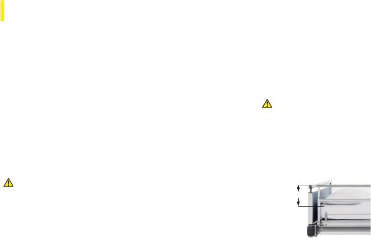
To minimise the risk of injury, only use mattresses with the dimensions and properties detailed above. If you do not use Völker mattresses, please contact a dealer in whom you have confidence.
DANGER The height of the raised side rail above the mattress must always be greater than or equal to 220 mm; otherwise the patient may accidentally fall out of bed. Please note that the height of the mattress has a direct influence on this.
WARNING Only original Völker
accessories should be used!
≥ 220 mm!
Content |
25 of 180 |
Help |
|
|
|
Völker bed model S 962-2 built after May 2009 – Service manual S33 |
V1.01 (09.08.2012) |
Use of securing systems
Securing systems such as belts or straps should only be used exactly as specified by the manufacturer.
If securing systems in the form of abdominal belts are used, then it must be ensured that the side rails are completely raised. In this case, the gap in the middle of the rails must be closed using a rail spacer.
Free Download Manual ManualsBooks.com
DANGER When using securing systems and rail spacers, please note the separate instructions for use pertaining to these accessories.
If the patient is restrained with the help of restraint holders, the lying surfaces must never be adjusted while the patient is restrained and must always be in the lowest position!
The lying surface adjustment functions must be locked when a patient is secured, and the hand control must be kept out of the patient's reach!
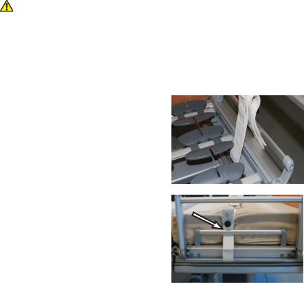
Restraints may be fastened directly onto beds built after 08/2009.
To do this, fasten the restraints on the corresponding longitudinal section of the lying surface frame. Make sure that the restraint is passed between the mattress holder and the mattress.
Initial startup
The lnitial startup section describes how the bed is first set up.
CONTENTS
General operating instructions 28
Preparation 29
Electrical activation 30
Using the battery pack 31
Taking out of service 32
Content |
27 of 180 |
Help |
|
|
|
Völker bed model S 962-2 built after May 2009 – Service manual S33 |
V1.01 (09.08.2012) |
On-time
The maximum On-time for the electromotive bed functions is specified on the bed (type label 160) or in the technical data sheet.
4 min./10 min. means that each electromotive adjustment may be operated for a maximum of 4 minutes, after which a pause of 10 minutes is necessary (protection against overheating).
NOTE Should the maximum Ontime of 4 minutes be exceeded repeatedly or for longer periods, safety cut-out devices on the bed may cause the electromechanical motor system to shut down. The bed must not be manoeuvred using the motors until it has cooled down sufficiently!
Free Download Manual ManualsBooks.com
Battery pack
The battery pack integrated in the double drive has a charge capacity that allows in theory a constant operation of 10 lifting and lying surface adjustments with a working load of 250 kg.
NOTE If the bed is parked at its location and the mains plug is not connected, this will cause the battery pack to discharge due
to the buffering of the electronic components!
Deep-discharged battery packs can be damaged to the extent that premature replacement is needed!
To increase the stand-by time, it is recommended to activate the reset button on the housing when storing the bed and to disconnect the bed from the mains. The bed should not be stored for a period longer than 6 months with a fully charged battery pack without recharging it.
Appropriate and correct use of the battery pack is essential for it to have a long service life!
In order to guarantee electrical functionality at all times, the bed should be connected to the mains as much as possible.
Safety cut-out device
The bed is equipped with an electrical, self-resetting safety cut-out device that prevents overloading of the motor systems. In the event of very severe overloading, the bed is automatically switched off.
 Loading...