


Service Manual (Arabic Video Version)
Model S 960-2

Help
Using hyperlinks
Hyperlinks are cross-references in the text (marked by ). Use the hyperlinks to jump to other locations in the same document, to other electronic documents including attachments, or to websites.
•Click to jump to another page, document, or website.
•Click  in the navigation bar to return to the previous location.
Searching for a word
•Click  to open the «Search PDF» window.
Use this to locate a word in the active PDF document. You can also use the advanced search options to search within other PDF documents.
Playing video clips
• Click the Play Video button to start playing the corresponding video clip.
It will take some seconds of loading time until a video clip starts playing. Video clips are available with the CDROM version only.
Additional interactive functions
Adobe Reader and all Adobe Acrobat program versions offer many features built into the normal screen view to assist you while working through PDF documents. For further information please consult the corresponding user manuals or the built-in help.
Jump to Table of Contents |
Jump to Help (for this page) |
Contents |
of 128 |
Help |
|
|
|
Völker Hospital Bed Model S 960-2 since Year of Manufacture April 2005 – Service Manual S25 |
V1.3 (Oct. 20, 2006) |
Version, Imprint, Identification Plate
Service Manual S25
Version 1.3 with Arabic videos (October 20, 2006)
for hospital bed model S 960-2 since year of manufacture April 2005
© by Völker AG 2006
Völker AG Wullener Feld 79 D-58454 Witten
GERMANY
Tel.: |
+49 |
2302 96096-62 |
Fax: |
+49 |
2302 96096-66 |
e-Mail: |
info@voelker.de |
|
Internet: www.voelker.de
All rights reserved. Reprinting in whole or in part is not permitted.
We reserve the right to make technical changes.
The content of this document is subject to change without notice.
Customers are advised to contact their sales representative before placing an order.
Contents
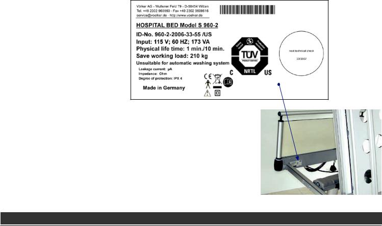
Identification plate
The identification plate is located on the inside, below the head board.
Move the back section up to read the identification plate.
For additional information on the identification plate, please refer to Appendix 109.
of 128 |
Help |
Völker Hospital Bed Model S 960-2 since Year of Manufacture April 2005 – Service Manual S25 |
V1.3 (Oct. 20, 2006) |
Table of Contents 1/2
Help 2
Version, imprint, identification plate
3
Table of contents 4
Notes and precautions 6
General information 7
General safety notes 8
Functional description 10 Overview 11
Nurse control with total lock 12
Nurse control with individual lock 13 Hand control with hook 14 Horizontal hand control 15 Configurations 16
Accessories 18
Initial start-up 19
General operating instructions 20 Preparation 21
Electrical start-up 22 Using the battery pack 23
Chasis UG4 25 Base frame 26 Frame 27
Mechanical brake 28 Castors 29
Castor replacement 30 Stroke head traverse 31
Stroke head traverse head section 31
Stroke head traverse foot section 32
Toothed belt replacement 33 Lifting motor replacement 36
Stroke pillar 37
Stroke pillar head and foot section with rod 37
Stroke pillar head and foot section w/o rod 38
Shaft cartridge replacement 39 Rod replacement 41
Cable looms 42
Cable loom replacement 43 Adjustment 44
Frame 45 Frame 46
Side profile assembly 47 Head profile assembly 48 Foot profile assembly 50 CPR direct mounting 51
CPR release lever replacement 52
Motor frame fitting 53
Motor frame fitting (back section) replacement 54
Bed extension (option) 55 Bed extension replacement 56
Lying Surface 58
Lying surface frame 59 Back section 60
Cross frame replacement 61 Upper leg / sitting section 62 Lower leg section 63
MiS® lying surface 64 Back section 65 Sitting section 66 Upper leg section 67 Lower leg section 68
Contents |
of 128 |
Help |
|
|
|
Völker Hospital Bed Model S 960-2 since Year of Manufacture April 2005 – Service Manual S25 |
V1.3 (Oct. 20, 2006) |

Table of Contents 2/2
HPL lying surface 69
Back section 70
Sitting section 71
Upper leg section 72
Lower leg section 73
Alu-flex lying surface 74
Side rails 75
Side rails back section 76 Side rails lower leg section 77 Side protection hand rail 78
Side protection handrail replacement 79
Telescopic extension replacement 80
Head and foot board 81 Head and foot board 82
Electronics 83 Electronics 84
Double drive replacement 85 Battery pack 87
Line power cut-off and battery replacement 88
Contents
Configurations 89 Drawer nurse control 90
Side holder nurse control 91 Bedding holder 92
Special drawer 93
Maintenance 94
Professional qualification 95 Safety regulations 95 Maintenance schedule 96
Technical check 97 Visual inspection 98
Functional check of side rails 98 Functional check of brakes 99 Functional check of drives 99 Electrical supply 99
Cabling 99
Casing 99
Mechanical inspection 99 Battery replacement 99 Measurement according to VDE 0751-1 100
Hand hold check 100
Troubleshooting 101
Troubleshooting list 102
Appendix 105
Spare part ordering 106 List of tools 106 Service points 106
Technical data (standard version) 107
Classification and symbols 108 Identification plate 109 Dimension sheet S 960-2 111 Product lifetime / disposal 112 Manufacturer‘s declarations, forms, interactive service manual 113
of 128 |
Help |
Völker Hospital Bed Model S 960-2 since Year of Manufacture April 2005 – Service Manual S25 |
V1.3 (Oct. 20, 2006) |

 Notes and Precautions
This chapter describes the intended use and the general precautions and restrictions to be observed when using the Völker hospital bed.
contents
General information 7 General safety notes 8
Contents |
of 128 |
Help |
|
|
|
Völker Hospital Bed Model S 960-2 since Year of Manufacture April 2005 – Service Manual S25 |
V1.3 (Oct. 20, 2006) |
 Notes and Precautions | General Information
General notes
Thank you for purchasing a Völker hospital bed. This hospital bed is manufactured according to national and international norms and standards, and incorporates state-of-the-art technology.
Völker hospital beds meet the demands of both safety and functionality. They have been tested against international norms and are designated with the CE seal, confirming that the basic requirements for medical products are met.
Please read the basic safety regulations (see also Instructions for Use). We also ask you to familiarize yourself with the additional notes given on the following pages, especially with regard to potential warranty claims.
Through this Service Manual, we wish to provide service technicians with appropriate guidelines for carrying out safe and competent work.
Every person who is in charge of carrying out maintenance as well as repair work, must at least have read
•the safety regulations and
•this service manual
and be qualified according to the local requirements.
In order to avoid errors and to ensure trouble-free operation of our hospital beds, these papers must always be available to the service staff (for professional qualification please refer to page 95 also).
Copyright protection
Providing these instructions to a third party for their use is permissible only upon prior written approval by the Völker AG. All of these documents are protected by copyright laws.
Warranty and liability
Within the limits of the warranty obligations specified by the main contract, Völker AG is liable only for potential defects or omissions, to the exclusion of further claims. Compensation claims are excluded, notwithstanding any legal argument upon which they might be based.
We reserve the right to make technical changes in this service manual without notice, in the course of the continuing development of these hospital beds.
We do not accept responsibility for damages and operational breakdowns that are caused by operating errors and noncompliance with these service instructions.
The indicated accessories will not necessarily correspond to the graphic illustrations.
Important information is marked by the following symbol:
Contents |
of 128 |
Help |
|
|
|
Völker Hospital Bed Model S 960-2 since Year of Manufacture April 2005 – Service Manual S25 |
V1.3 (Oct. 20, 2006) |

 Notes and Precautions | General Safety Notes 1/2
Safety alert symbol Information marked by this symbol must be read and strictly adhered to!
DANGER indicates a hazardous situation which, if not avoided, will result in death or serious injury.
WARNING indicates a hazardous situation which, if not avoided, could result in death or serious injury.
CAUTION indicates a hazardous situation which, if not avoided, may result in minor or moderate injury.
NOTICE indicates a property damage message.
Before starting maintenance work
Those persons who are responsible for carrying out maintenance service must read and thoroughly familiarize themselves with the content of this Service Manual prior to beginning any work.
Prior to beginning any warranty or repair work, authorized personnel must become thoroughly familiar with the operation of this bed, and be able to recognize in detail the risks described in this manual while carrying out the assembly and disassembly of the components of this bed.
The hospital beds are not flameproof which is why it is strictly forbidden to service them in an explosive environment, i.e. containing combustible substances.
WARNING Always disconnect the line power plug and the battery from the bed during maintenance.
Regulations
The Völker hospital bed must only be set up, operated and used according to its intended use to be in compliance with the legal regulations for medical products and any relevant issued statutory orders, and to comply with recognized engineering guidelines as well as the industrial regulations for safety and the prevention of accidents.
A hospital bed must not be operated if it is defective or might put patients, nursing staff or any third party at risk.
Contents |
of 128 |
Help |
|
|
|
Völker Hospital Bed Model S 960-2 since Year of Manufacture April 2005 – Service Manual S25 |
V1.3 (Oct. 20, 2006) |

 Notes and Precautions | General Safety Notes 2/2
Before initial start-up
Before putting the hospital bed into operation the first time, the nursing staff must have attended detailed training
in the handling of the bed. In addition, they must be made aware of potential hazards that might occur even when the bed is operated properly.
Moving the bed
Cleaning and disinfection
In order to maintain a consistent functional capability, the clinical bed should be cleaned, disinfected and tested at the soonest possible time following each use, so that it can be reused immediately without risk.
Dangers might occur by improper cleaning/disinfections of the bed.
CAUTION When moving the bed, ensure that the mattress frame is in the lowest position and that the back and leg sections of the mattress frame are completely lowered. Also ensure that the line power cable and power cut-off unit are not dragged along the ground or run over.
Service and Maintenance
Anyone who is responsible for carrying out maintenance or service on the Völker bed must at least have read the Safety Regulations and the Service Manual and be qualified according to the legal requirements.
After any maintenance or repair has been completed, it is absolutely necessary to check the bed for functional safety 98. The bed must be checked to determine whether it can be used without causing damage to the patients, employees or other persons.
A technical check 98 of the bed must be performed at least once per year and after long periods without operation.
If any damage is detected, such as signs of wear and tear, loose bolts and breaks, the damaged portion must be repaired or replaced immediately.
Electromagnetic/electrostatic interferences
The Völker S 960-2 hospital bed fulfils the electromagnetic compatibility requirements according to the EU
Directive 93/42/EEC concerning medical products. It has also been tested for compliance with the EN 60601-1-2 standard.
Contents |
of 128 |
Help |
|
|
|
Völker Hospital Bed Model S 960-2 since Year of Manufacture April 2005 – Service Manual S25 |
V1.3 (Oct. 20, 2006) |
 Functional Description
This chapter describes the functions and features of the Völker hospital bed.
Contents
Overview 11
Nurse control with total lock 12
Nurse control with individual lock 13
Hand control with hook 14 Horizontal hand control 15 Configurations 16 Accessories 18
Contents |
10 of 128 |
Help |
|
|
|
Völker Hospital Bed Model S 960-2 since Year of Manufacture April 2005 – Service Manual S25 |
V1.3 (Oct. 20, 2006) |
 Functional Description | Overview
Adjustable upper leg section
Adjustable lower leg section
Erectable side rails for back |
Adjustable |
section, on both sides |
back section |
Removable foot board
Nurse control,  pull out
Erectable side rails for lower leg section, on both sides
4-column telescopDouble foot brake, ing height adjuston both sides ment
Removable
 head board
CPR lever
(emergency release for back section to prepare the patient for applying cardio-pulmonary reanimation (CPR))
Hand control with hook
Sitting section, fixed
Contents |
11 of 128 |
Help |
|
|
|
Völker Hospital Bed Model S 960-2 since Year of Manufacture April 2005 – Service Manual S25 |
V1.3 (Oct. 20, 2006) |
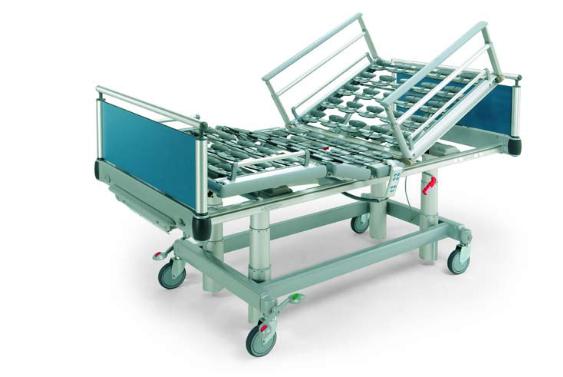
 Functional Description | Nurse Control with Total Lock
Rear side:
Reverse Trendelenburg position 1 |
Height adust- |
Back section |
Leg section |
Trendelenburg position 2 |
ment up/down 3 |
up/down |
up/down |
Nurse control unlocked
WARNING If any of the adjustable sections is raised with the side rails in their full upright position, ensure that no portions of the patient’s or anyone else’s body project through or lie on the side rail!
Contents
1Head elevated
2Head lowered
3The nurse control can be equipped with country-specific automatic functions (double click).
12 of 128
Nurse control and hand control are completely locked.
Help
Völker Hospital Bed Model S 960-2 since Year of Manufacture April 2005 – Service Manual S25 |
V1.3 (Oct. 20, 2006) |

 Functional Description | Nurse Control with Individual Lock (Option)
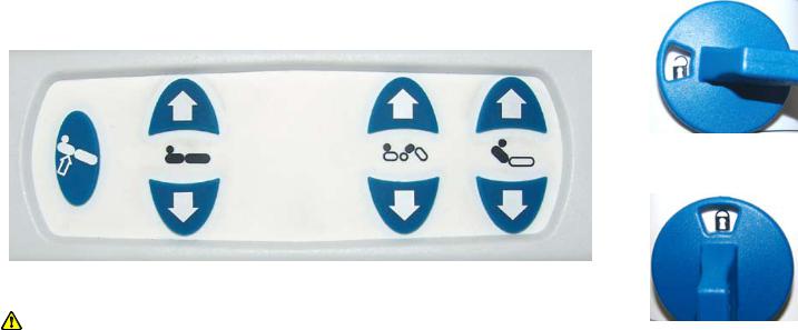
Back section |
Leg section |
Lying surface |
Reverse Trendelenburg position 1 |
up/down |
up/down |
up/down |
Trendelenburg position 2 |
The LED lights up red if the up or down button is pressed while the drive is locked.
Lock corresponding drive.
Unlock corresponding drive.
The LED lights up yellow when lying surface has reached its lowest position.
1 Head elevated; 2 head lowered
Contents |
13 of 128 |
WARNING If any of the adjustable sections is raised with the side rails in their full upright position, ensure that no portions of the patient’s or anyone else’s body project through or lie on the side rail!
Help
Völker Hospital Bed Model S 960-2 since Year of Manufacture April 2005 – Service Manual S25 |
V1.3 (Oct. 20, 2006) |
 Functional Description | Hand Control with Hook
Back section up
Leg section up
Lying surface up
Reverse Trendelenburg position 1
1Head elevated
Contents
Back section down |
|
Leg section down |
Hand control unlocked |
|
Lying surface down
Hand control locked
WARNING If any of the adjustable sections is raised with the side rails in their full upright position, ensure that no portions of the patient’s or anyone else’s body project through or lie on the side rail!
14 of 128 |
Help |
Völker Hospital Bed Model S 960-2 since Year of Manufacture April 2005 – Service Manual S25 |
V1.3 (Oct. 20, 2006) |
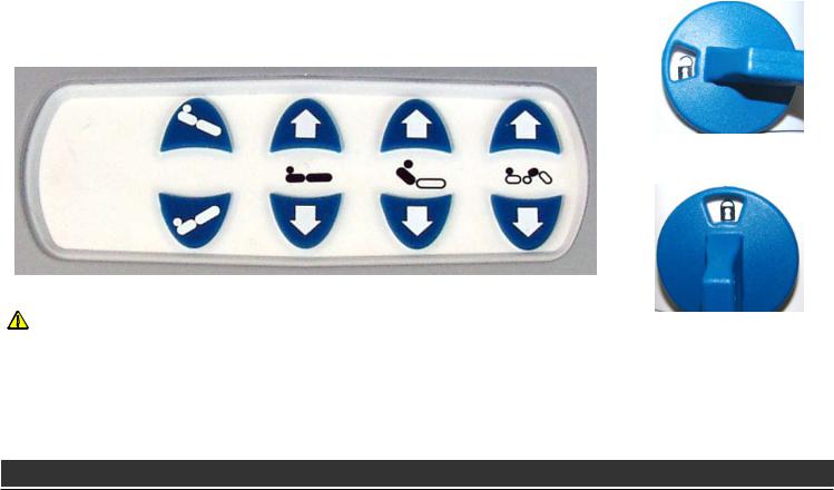
 Functional Description | Horizontal Hand Control (Option)
Rear side:
Reverse Trendelen- |
Lying surface |
Leg section |
Back section |
burg position 1 |
up/down |
up/down |
up/down |
Hand control unlocked
WARNING If any of the adjustable sections is raised with the side rails in their full upright position, ensure that no portions of the patient’s or anyone else’s body project through or lie on the side rail!
Hand control locked
1 Head elevated
Contents |
15 of 128 |
Help |
|
|
|
Völker Hospital Bed Model S 960-2 since Year of Manufacture April 2005 – Service Manual S25 |
V1.3 (Oct. 20, 2006) |
 Functional Description | Configurations 1/2
The S 960-2 standard model can be delivered in several configurations. These configurations are as follows:
Configuration |
Description |
Trapeze bar |
1. Single trapeze bar mounting, external. |
mounting |
The trapeze bar mounting is located in the |
|
middle, attached outside the lying surface |
|
(standard). |
|
2. Double trapeze bar mounting, internal. |
|
The trapeze bar mounting is located at the |
|
left and right inner side of the head board |
|
(option). |
|
The safe working load for the trapeze bar is |
|
75 kg. |
Hand control |
1. With hook (standard): |
Configuration |
Description |
Hand control |
2. Horizontal on side rail (option): |
(cont.) |
|
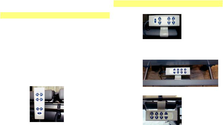
Nurse control 1. In storage drawer (standard) or bedding holder (option):
2. Snapped into the side holder (option):
Contents |
16 of 128 |
Help |
|
|
|
Völker Hospital Bed Model S 960-2 since Year of Manufacture April 2005 – Service Manual S25 |
V1.3 (Oct. 20, 2006) |
 Functional Description | Configurations 2/2
Configuration |
Description |
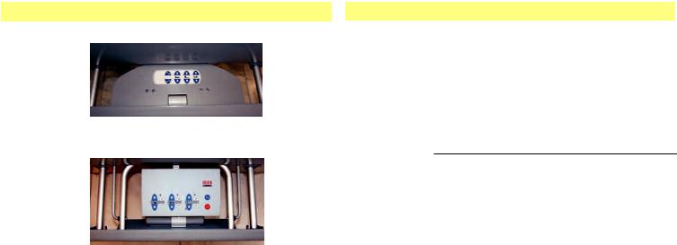
Nurse control |
3. In its special drawer (option): |
(cont.) |
|
4. With individual lock in bedding holder (option):
Castors |
The castors are of standard design |
|
(150 mm), but some types of customized |
|
castors can be delivered. The designs and |
|
the diameters can also be varied. This might |
|
result in a lifting adjustment range that var- |
|
ies by 20 mm. |
Configuration Description
Bed extenUsing the pull-out bed extension piece sion (option), you can extend the length of the
bed by 20 cm.
Side rails |
The S 960-2 bed can be provided in differ- |
|
ent types of side rails: |
Foot part / head part:
1.Extendable side rails 34* cm (standard)
2.Extendable side rails 40* cm (option)
*This dimension refers to the top edge of the side rail up to the lying surface (without mattress).
All the possible configurations are described in these instructions for use. You will find an overview of the configurations delivered in your bed order specification. If the original order specification is no longer available, please contact Völker customer service. Before contacting us, please note down the Völker ID-No. (see identification plate 109).
Contents |
17 of 128 |
Help |
|
|
|
Völker Hospital Bed Model S 960-2 since Year of Manufacture April 2005 – Service Manual S25 |
V1.3 (Oct. 20, 2006) |

 Functional Description | Accessories
Völker supplies an extensive range of easily installed accessories to provide the greatest possible flexibility. The hospital beds are equipped with holders for accessories such as IV holders or trapeze bars. Urine bottle baskets, universal hooks, standard bars, etc., can be mounted on the accessory bars provided on both sides of the bed.
Further information regarding the accessories can be found in our current brochure or on the internet at www.voelker.de . Our staff will gladly provide you with more details on the accessories that are available for your bed model.
Mattresses
To minimize the risk of injury, do not use this bed with mattresses of any size other than those described below. If you decide not to use a Völker mattress, contact a reputable dealer of your choice.
Size of mattress |
Size of mattress frame |
Volume weight |
88 x 200 x 12 cm |
90 x 200 cm |
40-50 kg/m3 |
88 x 220 x 12 cm |
90 x 220 cm |
40-50 kg/m3 |
98 x 200 x 12 cm |
100 x 200 cm |
40-50 kg/m3 |
98 x 220 x 12 cm |
100 x 220 cm |
40-50 kg/m3 |
WARNING The use of mattresses that do not correspond to these specifications will carry a risk of serious injury!
Use of restraint fastening systems
The use of fastening systems like belts is only allowed when these comply with the regulations of the manufacturer.
When using restraint fastening systems, the side rails must be in their full upright position. In this case, for model S 960-2 the gap in the middle must be secured with an side rail spacer.
DANGER Please take attention of the additional instructions for use for the fixation equipment provided for fastening systems.
It is strictly forbidden to move the mattress frame during a fastening process.
The mattress frame must be in the lowest possible position.
Deactivate all functions of the mattress frame during a fastening process, and place the hand control unit out of the patient’s reach.
Contents |
18 of 128 |
Help |
|
|
|
Völker Hospital Bed Model S 960-2 since Year of Manufacture April 2005 – Service Manual S25 |
V1.3 (Oct. 20, 2006) |
 Initial Start-Up
This chapter provides information on the initial start-up of the bed.
Contents
General operating instructions 20 Preparation 21
Electrical start-up 22 Using the battery pack 23
Contents |
19 of 128 |
Help |
|
|
|
Völker Hospital Bed Model S 960-2 since Year of Manufacture April 2005 – Service Manual S25 |
V1.3 (Oct. 20, 2006) |
 Initial Start-Up | General Operating Instructions
Power-on time
The maximum power-on time for the bed motor unit function is indicated on the bed (identification plate 109) and/ or in the technical data sheet, with the notation "1 min/10 min" meaning that when any bed function has been operated for 1 minute without interruption, the operation must be paused for 10 minutes, in order to protect the motor.
NOTICE If the maximum poweron time of 1 minute is exceeded before the 10 minute waiting period is over, either through separate operations or a longer continuous time period, this can lead to a failure of a motor unit due to safety devices being triggered. The bed will then be shut down for a period of 10 minutes.
Rechargeable batteries
The batteries in the bed have an electric charge capacity that is equivalent to 3 lifting and lying space adjustment operations, with a working load of 210 kg.
NOTICE If the bed is set up at its location without connecting it to the battery charger, energy consumption and self-discharge will lead to the discharge of the battery!
If the battery is totally discharged, it may be sufficiently damaged that early replacement becomes necessary.
In order to achieve a long battery life, proper handling of batteries and the battery charger is absolutely necessary!
To ensure operation of the electrical bed functions at any time, the system should preferably be connected to the line power supply.
Safety device
The bed is provided with an electronic safety device that prevents the drives from being overloaded.
Contents |
20 of 128 |
Help |
|
|
|
Völker Hospital Bed Model S 960-2 since Year of Manufacture April 2005 – Service Manual S25 |
V1.3 (Oct. 20, 2006) |
 Initial Start-Up | Preparation
Installation conditions
The bed is approved for operation in dry rooms only (Technical Data Sheet). In order for the bed to be operated, a power supply and, if necessary, a sense potential connection is required in the location where the bed is installed.
The bed is movable without auxiliary transport facilities. Unlock the bed‘s brake if it becomes necessary to move the bed.
The bed can be moved on solid ground only. It is not permissible to drive the bed over an obstacle higher than 2 cm. The maximum permissible angle of inclination for the path of movement is 10°.
Mechanical start-up
The head and foot boards provided must be inserted into the corner joints of the bed frame.
Connecting the hand control
The hand controls must be plugged into the jacks provided. Do not place stress on the coiled cable.
Arrangement of the hand control coiled cable
Contents |
21 of 128 |
Help |
|
|
|
Völker Hospital Bed Model S 960-2 since Year of Manufacture April 2005 – Service Manual S25 |
V1.3 (Oct. 20, 2006) |

 Initial Start-Up | Electrical Start-up
WARNING Make certain that the connection between the line power cut-off and the drive for the lying surface is made correctly!
NOTICE Be aware that improper use of the line power cut-off can damage the unit, with the result that the batteries can no longer be charged.
NOTICE Do not drop the line power cut-off plug. Do not pull or exert excessive strain on any electrical cables or connections. Take care not to run over the line power cable when moving the bed.
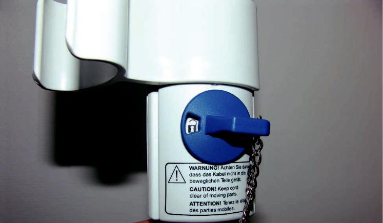
1.Connect the line power cut-off plug to a line outlet.
Line power cut-off plug
2.Unlock the hand control and the nurse control by means of the socket key, in order to activate their electrical functions.
Unlocked padlock icon visible
Socket key
Contents |
22 of 128 |
Help |
|
|
|
Völker Hospital Bed Model S 960-2 since Year of Manufacture April 2005 – Service Manual S25 |
V1.3 (Oct. 20, 2006) |
 Initial Start-Up | Using the Battery Pack 1/2
The rechargeable battery pack enables line power-free operation of the bed for at least 3 switch-on cycles.
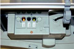
The LED lights up in three colors:
Green |
Battery pack is connected |
|
to the line power. Charg- |
|
ing cycle is on. |
Orange |
Battery pack is cur- |
|
rently being charged. Bed |
|
should not be operated |
|
free of the line power. |
Red |
HAZARDOUS RANGE. |
|
Battery pack must be |
|
charged. Bed cannot be |
|
operated free from the |
|
line power. |
All LEDs |
Battery is completely |
are off |
charged or cut-off and not |
|
connected to power: Line |
|
power cut-off is activated. |
|
No current flow in stand- |
|
by mode. |
If a beeping sound is heard, the battery pack needs to be recharged. The beep sound becomes weaker the further the battery pack has been discharged. The battery pack will switch off shortly before total discharge. After the bed has been connected to the line power, press any button in the hand control in order to make it fully functional again. The battery pack starts a charging cycle when it is connected to the line power after each use, or when the charge has dropped too low.
NOTICE If the bed is not connected to the line power for a longer period, the battery pack can become discharged. The level of discharge is dependent on the ambient conditions.
NOTICE During the charging cycles, the battery pack is connected to the line power and is thus being supplied with electricity. The LED shows the charging status of the battery pack during the charging cycle. The circuit breaker is disabled, with electric current flowing to the bed.
Contents |
23 of 128 |
Help |
|
|
|
Völker Hospital Bed Model S 960-2 since Year of Manufacture April 2005 – Service Manual S25 |
V1.3 (Oct. 20, 2006) |

 Initial Start-Up | Using the Battery Pack 2/2
WARNING If electromagnetic disturbances due to other appliances are produced in the vicinity of the bed, please refrain from operating these appliances.
In case of transport, the device must always be handled carefully and protected from moisture.
NOTICE This equipment is specified for use at an ambient temperature of 10 °C to 40 °C, relative humidity of 30% to 40% and for barometric pressure of 700 to 1,060 hPa.
WARNING The battery pack should only be replaced by trained personnel from Völker AG.
WARNING A faulty battery pack might begin to produce gas emissions. In rare cases this can cause deformations in the battery pack casing. If this occurs, take the bed out of service immediately and move the bed
into a well aired room without any sparking formation (electrical or fire sparks). Contact customer service immediately!
WARNING You should dispose of the battery pack at suitable facilities in order to protect the environment, or you are welcome to return it to the Völker AG.
In order to operate the hand control and the nurse control after switching on the bed, the lock on the function keys must be released.
Contents |
24 of 128 |
Help |
|
|
|
Völker Hospital Bed Model S 960-2 since Year of Manufacture April 2005 – Service Manual S25 |
V1.3 (Oct. 20, 2006) |
 Chassis UG4
This chapter provides the exploded views, the subassembly parts lists and a detailed description of the parts replacement and adjustment procedures.
Contents
Base frame 26 Frame 27 Mechanical brake 28
Castors 29
Castor replacement 30
Stroke head traverse 31
Stroke head traverse head section 31
Stroke head traverse foot section 32
Toothed belt replacement 33 Lifting motor replacement 36
Stroke pillar 37
Stroke pillar head and foot section with rod 37
Stroke pillar head and foot section w/o rod 38
Shaft cartridge replacement 39 Rod replacement 41
Cable looms 42
Cable loom replacement 43 Adjustment 44
Contents |
25 of 128 |
Help |
|
|
|
Völker Hospital Bed Model S 960-2 since Year of Manufacture April 2005 – Service Manual S25 |
V1.3 (Oct. 20, 2006) |

 Chassis UG4 | Base Frame
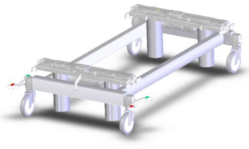
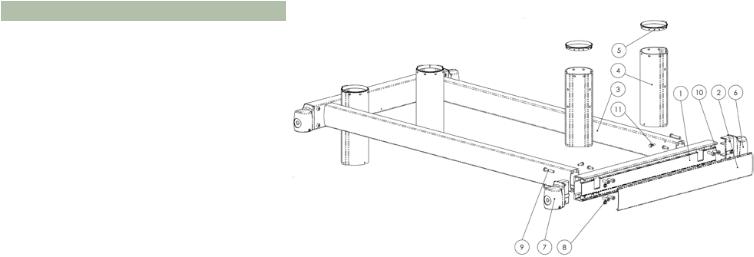
Base frame S 960-2 UG4, BG476
Pos |
Mat. No. |
Item |
No. |
|
|
|
|
1 |
BG470 |
Frame UG4 |
1 |
|
|
|
|
2 |
BG471 |
Mechanical brake UG4 |
1 |
3 |
BG472 |
Castors UG4 |
1 |
|
|
|
|
4 |
BG480 |
Stroke pillar, foot section, |
1 |
|
|
UG4, without rod |
|
5 |
BG479 |
Stroke pillar, foot section, |
1 |
|
|
UG4, with rod |
|
6 |
BG478 |
Stroke pillar, head section, |
1 |
|
|
UG4 without rod |
|
7 |
BG477 |
Stroke pillar, head section, |
1 |
|
|
UG4, with rod |
|
8 |
BG482 |
Stroke head traverse, foot |
1 |
|
|
section, mounted |
|
9 |
BG481 |
Stroke head traverse, head |
1 |
|
|
section, mounted |
|
10 |
K514 |
Cable loom, foot section, |
1 |
|
|
with 3 end switches |
|
11 |
K513 |
Cable loom, head section, |
1 |
|
|
with 5 end switches |
|
Contents |
26 of 128 |
Help |
|
|
|
Völker Hospital Bed Model S 960-2 since Year of Manufacture April 2005 – Service Manual S25 |
V1.3 (Oct. 20, 2006) |
 Chassis UG4 | Frame
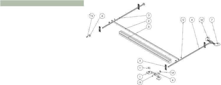
Frame UG4, BG470
Pos |
Mat. No. |
Item |
No. |
1 |
AP2211 |
Cross section UG4 |
2 |
|
|
|
|
2 |
AP2062 |
Face plate, cross bearer |
2 |
3 |
AP2214 |
Lengthwise profile UG4 |
2 |
|
|
|
|
4 |
AP2218 |
Outside foot UG4 150er castor |
4 |
|
|
|
|
5 |
KT2148 |
Slip ring, outside foot |
4 |
6 |
F2062 |
Castor mounting, right |
2 |
|
|
|
|
7 |
F2072 |
Castor mounting, left |
2 |
8 |
SR469 |
Hexagon nut M8 DIN 985 A2 |
8 |
|
|
|
|
9 |
SR739 |
Flat head screw M8x45 ISO |
8 |
|
|
7380 zinc coated |
|
10 |
SR596 |
Cylinder head screw EM8x23 |
16 |
|
|
DIN 7500 Dacro |
|
11 |
SR2110 |
Hexagon screw with collar |
16 |
|
|
M6x20 DIN 7500 zinc coated |
|
Contents |
27 of 128 |
Help |
|
|
|
Völker Hospital Bed Model S 960-2 since Year of Manufacture April 2005 – Service Manual S25 |
V1.3 (Oct. 20, 2006) |
 Chassis UG4 | Mechanical Brake
Mechanical brake, BG471
Pos |
Mat. No. |
Item |
No. |
|
|
|
|
1 |
F2068-02 |
Dual break lever |
2 |
|
|
|
|
2 |
F2279 |
Push rod |
1 |
3 |
F2093 |
Break shaft, head section, UG3 |
1 |
|
|
|
|
4 |
F2095 |
Break shaft, foot section, UG3 |
1 |
5 |
KT216 |
Insulation band 3 |
1 |
|
|
|
|
6 |
KT2035 |
Tread rubber, red, right |
1 |
7 |
KT2036 |
Tread rubber, red, left |
1 |
|
|
|
|
8 |
KT2049 |
Cover for castor mounting |
2 |
9 |
KT2050 |
Shaft guide 2 for hexagonal |
4 |
|
|
shaft 11 mm |
|
10 |
KT2051 |
Tread rubber, green, right |
1 |
|
|
|
|
11 |
KT2052 |
Tread rubber, green, left |
1 |
12 |
SR162 |
Lock washer 6 DIN 6799 A2A |
2 |
|
|
|
|
13 |
SR471 |
Fillister head screw M6x16 |
2 |
|
|
ISO7380 A2 |
|
14 |
SR742 |
Lock washer 28x14.2x1.5 |
2 |
15 |
SR537 |
Cylinder screw with Precote80 |
2 |
|
|
M6x20 DIN7984 A2 |
|
Contents |
28 of 128 |
Help |
|
|
|
Völker Hospital Bed Model S 960-2 since Year of Manufacture April 2005 – Service Manual S25 |
V1.3 (Oct. 20, 2006) |
 Chassis UG4 | Castors
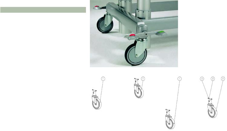
Castors UG4, BG472
Pos |
Mat. No. |
Item |
No. |
|
|
|
|
1 |
R2010 |
Steering castor with direction |
1 |
|
|
adjuster (standard) |
|
2 |
R2011 |
Steering castor with central |
3 |
|
|
adjuster (standard) |
|
3 |
SR537 |
Cylinder head screw with Pre- |
8 |
|
|
cote80 M6x20 DIN 7984 A2 |
|
4 |
SR501 |
Spring lock ring 6 DIN 7980 A4. |
8 |
|
|
|
|
Contents |
29 of 128 |
Help |
|
|
|
Völker Hospital Bed Model S 960-2 since Year of Manufacture April 2005 – Service Manual S25 |
V1.3 (Oct. 20, 2006) |

 Chassis UG4 | Castor Replacement
1.Remove the cylinder head screw in the center of the dual break lever (w/o Fig).
2.Remove the dual break lever from the break shaft. If tight, use rubber mallet (Fig 2.).
3.Remove face blade by means of a screw driver or plastic wedge form the cross section (clamp-connection) (Fig 3.).
4.Remove both fillister screws (Fig 4.).
5.Remove caster mounting from the break shaft (Fig 5.).
6Remove both fit-up aid screws from the caster mounting (Fig 6.).
Important: Both fit-up aid screws are fastened and have to be refastened when rescrewing (Loctite blue).
7.Remove caster mounting from castor pin (Fig 7.).
8.Reassemble in revers sequence (w/o Fig). Important: Observe switch cam during assembly!
|
Fig 3. |
Fig 2. |
Fig 4. |
Fig 5. |
Fig 6. |
Fig 7. |
Contents |
30 of 128 |
Help |
|
|
|
Völker Hospital Bed Model S 960-2 since Year of Manufacture April 2005 – Service Manual S25 |
V1.3 (Oct. 20, 2006) |
 Loading...