


VT-Series
Ice Maker
Model
VT40, VT60, VT80, VT100
Revision Date: 1/04/12
NOTICE
This manual is the property of the owner of this particular Vogt Tube-Ice® machine.
Model #____________________ Serial #____________________.
It is to be left on the premises with this machine at all times. After start-up, it should be stored in a safe place where it can be readily available when needed for future reference in maintaining troubleshooting or servicing.
Failure to comply with this notice will result in unnecessary inconvenience and possible additional expenses.
This manual is intended as an informational tool for the installation, operation, maintenance, troubleshooting, and servicing of this equipment. If an existing situation calls for additional information not found herein, we suggest that you contact your distributor first. If further assistance or information is needed, please feel free to contact the factory at 502-635-3000 or FAX at 502-635-3024.
IMPORTANT: The Warranty Registration/Start-Up Report found in the front of this manual is to be completed and returned to the factory promptly after the official start-up.
Please return to: |
VOGT ICE , LLC |
|
1000 W. Ormsby Ave. |
|
Louisville, KY 40210 |
FOREWORD
Vogt Ice®, LLC, strives to provide a quality product that is time-tested and will provide years of dependable service to its customers.
Skilled craftsmen have carefully assembled your Vogt® VT Series ice maker using material components and parts available from the leading vendors and producers of the highest quality refrigeration equipment in our industry. You have invested in quality equipment, and we pledge to support your needs and requirements after the sale.
This manual is provided to aid the service technician and users in the installation, operation, and maintenance of your equipment. Before attempting to install and start the machine, the installer should read and understand each section of this manual.
If, at any time, you encounter conditions that we have not addressed in this manual, we welcome you to write or call Vogt® Ice, LLC and we will give your questions our immediate attention and reply.
Vogt Ice®, LLC
1000 W. Ormsby Avenue
Suite 19
Louisville, KY 40210
(502)635-3000
(502)634-3024 Fax
TABLE OF CONTENTS
General Information - Section 1
History of Company............................................................................................. |
1-1 |
Receipt of Your Ice Machine ............................................................................... |
1-2 |
Installation Information - Section 2
Important Safety Notice ....................................................................................... |
2-1 |
Machine Dimension............................................................................................. |
2-2 |
Machine Weights & Refrigerant Line Sizes.......................................................... |
2-2 |
Ice Chute Cutout ................................................................................................. |
2-3 |
Water Connections.............................................................................................. |
2-4 |
Water Flow Rates / Water Tank Capacity............................................................ |
2-4 |
Electrical Connections......................................................................................... |
2-5 |
Air Cooled Condenser Electrical Connections .................................................... |
2-6 |
Lowside Electrical Connections .............................................................................. |
2-6 |
Air Cooled Condenser Installation ....................................................................... |
2-7 |
Air Cooled Condenser Wiring ............................................................................. |
2-9 |
Storing Ice – Bin Thermostat Mounting ............................................................. |
2-12 |
Model Specifications and Wiring Diagrams - Section 3
Model Specifications ........................................................................................... |
3-1 |
Model Number Structure .................................................................................... |
3-2 |
Initial Startup - Section 4
Startup Procedure ............................................................................................... |
4-1 |
Circuit Breakers & Lowside Control Panel Front.................................................. |
4-2 |
Service Valve Locations ...................................................................................... |
4-3 |
Adding Refrigerant .............................................................................................. |
4-4 |
Suction Line Access Port..................................................................................... |
4-4 |
Removing Refrigerant ......................................................................................... |
4-5 |
Electrical Controls - Section 5
Explanation of Controls........................................................................................ |
5-1 |
Startup & Standby Mode ..................................................................................... |
5-1 |
Freeze Mode ...................................................................................................... |
5-1 |
PLC & Freezer Timer .......................................................................................... |
5-1 |
Harvest Mode ...................................................................................................... |
5-2 |
Harvest Hold Pressure Switch (Increasing Harvest) ............................................... |
5-2 |
Clean Mode ......................................................................................................... |
5-3 |
Fault Mode & Faults Designations ....................................................................... |
5-3 |
PLC Input / Output Table ..................................................................................... |
5-4 |
Electrical Schematic (Standard) ............................................................................ |
5-5 |
Electrical Schematic (CE)..................................................................................... |
5-6 |
Lowside Electrical Schematic .............................................................................. |
5-7 |
Lowside Control Panel Layout ............................................................................ |
5-8 |
Condensing Unit Electrical Schematic (Standard) ................................................. |
5-9 |
Condensing Unit Control Panel Layout (Standard).............................................. |
5-10 |
Condensing Unit Electrical Schematic (CE) ....................................................... |
5-11 |
Condensing Unit Control Panel Layout (CE) ...................................................... |
5-12 |
Maintenance - Section 6
Preventive Maintenance ..................................................................................... |
6-1 |
Preventive Maintenance Program ....................................................................... |
6-2 |
Air Cooled Condenser Cleaning .......................................................................... |
6-3 |
Compressor Oil ................................................................................................... |
6-3 |
Chopper Gear Reducer Oil .................................................................................. |
6-4 |
Water Distributor ................................................................................................. |
6-4 |
Troubleshooting - Section 7
Machine Fault Light ............................................................................................ |
7-1 |
Control Power Light ............................................................................................ |
7-1 |
PLC ..................................................................................................................... |
7-2 |
Damaged Bin Control Sensor .............................................................................. |
7-2 |
Machine Inoperative ............................................................................................ |
7-3 |
Machine “Freeze-Up”........................................................................................... |
7-4 |
Additional Troubleshooting ................................................................................. |
7-5 |
Service Operations - Section 8
Principle Of Operation ........................................................................................ |
8-1 |
Pressure Switches .............................................................................................. |
8-2 |
CoreSense (Copeland Compressor Protection)........................................................ |
8-3 |
Bin Control (Electronic Temperature Control) ........................................................... |
8-4 |
PLC (Programmable Logic Controller)...................................................................... |
8-5 |
Compressor......................................................................................................... |
8-6 |
TXV & Solenoid Valve ......................................................................................... |
8-7 |
Adjusting TXV...................................................................................................... |
8-8 |
Inlet Pressure Regulator ...................................................................................... |
8-8 |
Water Tank Parts ............................................................................................... |
8-9 |
Chopper Assembly ........................................................................................... |
8-10 |
Evaporator Housing Covers .............................................................................. |
8-11 |
Freeze Cycle Piping Schematic (No Hot Gas Loop) ............................................ |
8-12 |
Harvest Cycle Piping Schematic (No Hot Gas Loop) ........................................... |
8-13 |
Freeze Cycle Piping Schematic (With Hot Gas Loop) .......................................... |
8-14 |
Harvest Cycle Piping Schematic (With Hot Gas Loop) ......................................... |
8-15 |
Freeze Cycle Piping Schematic (With Suction Stop Valve) ...................................... |
8-16 |
Harvest Cycle Piping Schematic (With Suction Stop Valve) ..................................... |
8-17 |
Replacement Parts List .................................................................................... |
8-18 |
Options and Accessories - Section 9
Voltage Monitor (Wagner Model DTP-3) ................................................................... |
9-1 |
Remote Switch (Includes Ice/Off/Clean selector switch, start button & fault light) ........... |
9-3 |
Vogt® VT Service Manual |
1-1 |
|
General Information |
1. General Information
HISTORY OF COMPANY
Henry Vogt Machine Co. was founded as a small machine shop in Louisville, Kentucky in
1880. In 1938, Vogt built the first Tube-Ice® machine and revolutionized the ice-making industry. Our first “sized-ice” machine quickly replaced the old can-ice plants, which required much hard labor and large amounts of floor space for freezing, cutting, and crushing ice by hand.
Today, Vogt Ice , LLC carries on the tradition as one of the world’s leading producers of icemaking equipment.
Preview Vogt VT Series ice machines are built with the skill in engineering and fabrication that we have learned in over a century of ice machine manufacturing.
Furnished with your machine is the “Certificate of Test”--the report of operating data that is a record of the unit’s satisfactory operation on our factory test floor.
This manual is designed to assist you in the installation, start-up, and maintenance of your
unit. Your VT® machine will give you many years of service when you install it, maintain it, and service it properly.
Please read your manual carefully before attempting installation, operation, or servicing of this piece of equipment.
If you have additional questions, please call your distributor. Also, feel free to phone the factory direct at (502) 635-3000 or 1-800-853-8648.

1-2 |
Vogt® VT Service Manual |
General Information |
|
|
Receipt Of Your Ice Machine |
!CAUTION !
Only service personnel experienced in refrigeration and qualified to work on high amperage electrical equipment should be allowed to install or service this VT ice machine.
Eye protection should be worn by all personnel working on or around the VT machine.
It is very important that you are familiar with and adhere to all local, state, and federal, etc. ordinances and laws regarding
the handling, storing, and use of R404A.
!CAUTION !
Inspection. As soon as you receive your machine, inspect it for any damage. If damage is suspected, note it on the shipper’s papers (i.e., the trucker’s Bill of Lading). Immediately make a separate written request for inspection by the freight line’s agent. Any repair work or alteration to the machine without the permission of the Vogt Ice can void the machine’s warranty. You should also notify your Vogt distributor or the factory.
Safety Tags and Labels. Be sure to read and adhere to all special tags and labels attached to valves or applied to various areas of the machine. They provide important information necessary for safe and efficient operation of your equipment.

Vogt® VT Service Manual |
2-1 |
|
Installation Instructions |
2.Installation Information
This information is intended for use by individuals possessing adequate backgrounds of electrical, refrigeration and mechanical experience. Any attempt to repair major equipment may result in personal injury and property damage. The manufacturer or seller cannot be responsible for the interpretation of this information, nor can it assume any liability in connection with its use.
Special Precautions To Be Observed When Charging Refrigeration Systems. Only
technically-qualified persons, experienced and knowledgeable in the handling of refrigerant and operation of refrigeration systems, should perform the operations described in this manual. All local, federal, and EPA regulations must be strictly adhered to when handling refrigerants.
If a refrigeration system is being charged from refrigerant cylinders, disconnect each cylinder when empty or when the system is fully charged. A gage should be installed in the charging line to indicate refrigerant cylinder pressure. The cylinder may be considered empty of liquid R404A refrigerant when the gage pressure is 25 pounds or less, and there is no frost on the cylinder. Close the refrigerant charging valve and cylinder valve before disconnecting the cylinder. Loosen the union in the refrigerant charging line-- carefully to avoid unnecessary and illegal release of refrigerant into the atmosphere.
!CAUTION !
Immediately close system charging valve at commencement of defrost or thawing cycle if refrigerant cylinder is connected. Never leave a refrigerant cylinder connected to system except during charging operation. Failure to observe either of these precautions can result in transferring refrigerant from the system to the refrigerant cylinder, over-filling it, and possibly causing the cylinder to rupture because of pressure from expansion of the liquid refrigerant brought on by an increase in temperature.
!CAUTION !
Always store cylinders containing refrigerant in a cool place. They should never be exposed to temperatures higher than 110°F and should be stored in a manner to prevent abnormal mechanical shocks. Also, transferring refrigerant from a refrigeration system into a cylinder can be very dangerous and is not recommended.
! CAUTION !
It is not recommended that refrigerant be transferred from a refrigeration system directly into a cylinder. If such a transfer is made, the refrigerant cylinder must be an approved, CLEAN cylinder--free of any contaminants or foreign materials--and must be connected to an approved recovery mechanism with a safety shutoff sensor to assure contents do not exceed net weight specified by cylinder manufacturer or any applicable code requirements.
! CAUTION !

2-2 |
Vogt® VT Service Manual |
Installation Instructions |
|
58" - VT40, VT60
& VT80
71" - VT100
FIGURE 2-1
Ice Machine Dimensions
Unit |
"A" |
"B" |
"C" |
"D" |
"E" |
"F" |
VT40 |
72 5/8" |
27" |
24 3/8" |
50 3/4" |
44" |
34" |
VT60 |
89" |
39 1/2" |
30 1/2" |
63 1/4" |
57.5 |
68" |
VT80 & VT100 |
44 7/8" |
|
|
|
N/A |
N/A |
TABLE 2-1
Ice Machine Dimensions
|
Remote Weights |
Skid Mounted Weights |
|
||
Model |
Lowside |
Condensing Unit |
Model |
Skid Mounted |
|
VT40 |
520 lbs. |
975 lbs. |
VT-40 |
1,525 lbs. |
|
VT60 |
650 lbs. |
1330 lbs. |
VT-60 |
2290 lbs. |
|
VT80 |
1,475 lbs. |
375 lbs. (condenser) |
VT-80 |
---------- |
|
VT100 |
1,850 lbs. |
400 lbs. (condenser) |
VT-100 |
---------- |
|
TABLE 2-2
Weight Of Machines
|
Suction |
Hot Gas |
Liquid |
Remote Condenser |
|
|
|
|
|
|
|
Model |
Line |
Line |
Line |
Discharge |
Liquid Return |
VT40 |
1 3/8 OD |
7/8 OD |
5/8 OD |
N/A |
N/A |
VT60 |
|
1 1/8 OD |
7/8 OD |
|
|
VT80 |
1 5/8 OD |
|
|
1 1/8 OD |
7/8 OD |
VT100 |
|
|
|
1 3/8 OD |
|
Note: Split systems will be supplied with Rota-lock adapters to connect the highside to the lowside
TABLE 2-3
Refrigerant Line Sizes
Machine Clearances: A minimum three (3) feet of clearance is recommended around entire ice machine. This will provide sufficient area for service and air flow.
Mount evaporator section (lowside) on storage area capable of sustaining its weight and secure by thru bolting.
Note: Ambient at the lowside should remain between 50ºF–105ºF. Makeup water temperature should not drop below 40ºF.

Vogt® VT Service Manual |
2-3 |
|
Installation Instructions |
Piping Installation: Use ACR refrigeration tubing and nitrogen purge during brazing to prevent formation of copper oxide. For piping runs exceeding 25’, consult a reliable piping manual (Copeland, Heatcraft, or Vilter) for proper pipe sizing. Heat sink all ball valves and remove Schrader valve core prior to brazing. Pressure test piping for leaks. Evacuate lines to 500 microns prior to starting machine.
Using drawing and table below, determine ice machine location so that it is centered on bin. Place ice machine on ice storage unit and bolt in place. Machine must be level front to back and side to side for proper operation.


 27” (VT40)


 39 1/2” (VT60, VT80 & VT100)
Skid Mounted


 27” (VT40)


 39 1/2” (VT60, VT80 & VT100)
Split System
FIGURE 2-2
Ice Chute Cutout Location
2-4 |
|
|
|
|
|
|
|
|
|
|
|
|
|
|
|
|
|
|
|
|
|
|
|
|
|
|
|
|
|
|
|
|
|
|
|
|
|
|
|
|
|
|
|
|
|
|
|
|
|
|
|
|
|
|
|
|
|
|
|
|
|
|
|
|
|
|
|
|
|
|
|
|
|
|
|
|
|
|
|
|
|
|
|
|
|
|
|
|
|
|
|
|
|
|
Vogt® VT Service Manual |
||||||||||||||||||||||||||||||||||||||
Installation Instructions |
|
|
|
|
|
|
|
|
|
|
|
|
|
|
|
|
|
|
|
|
|
|
|
|
|
|
|
|
|
|
|
|
|
|
|
|
|
|
|
|
|
|
|
|
|
|
|
|
|
|
|
|
|
|
|
|
|
|
|
|
|
|
|
|
|
|
|
|
|
|
|
|
|
|
|
|
|
|
|
|
|
|
|
|
|
|
|
||||||||||||||||||||||||||||||||||||||||||||||
|
|
|
|
|
|
|
|
|
|
|
|
|
|
|
|
|
|
|
|
|
|
|
|
|
|
|
|
|
|
|
|
|
|
|
|
|
|
|
|
|
|
|
|
|
|
|
|
|
|
|
|
|
|
|
|
|
|
|
|
|
|
|
|
|
|
|
|
|
|
|
|
|
|
|
|
|
|
|
|
|
|
|
|
|
|
|
|
|
|
|
|
|
|
|
|
|
|
|
|
|
|
|
|
|
|
|
|
|
|
|
|
|
|
|
|
|
|
|
|
|
|
|
|
|
|
|
|
|
|
|
|
|
|
|
|
|
|
|
|
|
|
|
|
|
|
|
|
|
|
|
|
|
|
|
|
|
|
|
|
|
|
|
|
|
|
|
|
|
|
|
|
|
|
|
|
|
|
|
|
|
|
|
|
|
|
|
|
|
|
|
|
|
|
|
|
|
|
|
|
|
|
|
|
|
|
|
|
|
|
|
|
|
|
|
|
|
|
|
|
|
|
|
|
|
|
|
|
|
|
|
|
|
|
|
|
|
|
|
|
|
|
|
|
|
|
|
|
|
|
|
|
|
|
|
|
|
|
|
|
|
|
|
|
|
|
|
|
|
|
|
|
|
|
|
|
|
|
|
|
|
|
|
|
|
|
|
|
|
|
|
|
|
|
|
|
|
|
|
|
|
|
|
|
|
|
|
|
|
|
|
|
|
|
|
|
|
|
|
|
|
|
|
|
|
|
|
|
|
|
|
|
|
|
|
|
|
|
|
|
|
|
|
|
|
|
|
|
|
|
|
|
|
|
|
|
|
|
|
|
|
|
|
|
|
|
|
|
|
|
|
|
|
|
|
|
|
|
|
|
|
|
|
|
|
|
|
|
|
|
|
|
|
|
|
|
|
|
|
|
|
|
|
|
|
|
|
|
|
|
|
|
|
|
|
|
|
|
|
|
|
|
|
|
|
|
|
|
|
|
|
|
|
|
|
|
|
|
|
|
|
|
|
|
|
|
|
|
|
|
|
|
|
|
|
|
|
|
|
|
|
|
|
|
|
|
|
|
|
|
|
|
|
|
|
|
|
|
|
|
|
|
|
|
|
|
|
|
|
|
|
|
|
|
|
|
|
|
|
|
|
|
|
|
|
|
|
|
|
|
|
|
|
|
|
|
|
|
|
|
|
|
|
|
|
|
|
|
|
|
|
|
|
|
|
|
|
|
|
|
|
|
|
|
|
|
|
|
|
|
|
|
|
|
|
|
|
|
|
|
|
|
|
|
|
|
|
|
|
|
|
|
|
|
|
|
|
|
|
|
|
|
|
|
|
|
|
|
|
|
|
|
|
|
|
|
|
|
|
|
|
|
|
|
|
|
|
|
|
|
|
|
|
|
|
|
|
|
|
|
|
|
|
|
|
|
|
|
|
|
|
|
|
|
|
|
|
|
|
|
|
|
|
|
|
|
|
|
|
|
|
|
|
|
|
|
|
|
|
|
|
|
|
|
|
|
|
|
|
|
|
|
|
|
|
|
|
|
|
|
|
|
|
|
|
|
|
|
|
|
|
|
|
|
|
|
|
|
|
|
|
|
|
|
|
|
|
|
|
|
|
|
|
|
|
|
|
|
|
|
|
|
|
|
|
|
|
|
|
|
|
|
|
|
|
|
|
|
|
|
|
|
|
|
|
|
|
|
|
|
|
|
|
|
|
|
|
|
|
|
|
|
|
|
|
|
|
|
|
|
|
|
|
|
|
|
|
|
|
|
|
|
|
|
|
|
|
|
|
|
|
|
|
|
|
|
|
|
|
|
|
|
|
|
|
|
|
|
|
|
|
|
|
|
|
|
|
|
|
|
|
|
|
|
|
|
|
|
|
|
|
|
|
|
|
|
|
|
|
|
|
|
|
|
|
|
|
|
|
|
|
|
|
|
|
|
|
|
|
|
|
|
|
|
|
|
|
|
|
|
|
|
|
|
|
|
|
|
|
|
|
|
|
|
|
|
|
|
|
|
|
|
|
|
|
|
|
|
|
|
|
|
|
|
|
|
|
|
|
|
|
|
|
|
|
|
|
|
|
|
|
|
|
|
|
|
|
|
|
|
|
|
|
|
|
|
|
|
|
|
|
|
|
|
|
|
|
|
|
|
|
|
|
|
|
|
|
|
|
|
|
|
|
|
|
|
|
|
|
|
|
|
|
|
|
|
|
|
|
|
|
|
|
|
|
|
|
|
|
|
|
|
|
|
|
|
|
|
|
|
|
|
|
|
|
|
|
|
|
|
|
|
|
|
|
|
|
|
|
|
|
|
|
|
|
|
|
|
|
|
|
|
|
|
|
|
|
|
|
|
|
|
|
|
|
|
|
|
|
|
|
|
|
|
|
|
|
|
|
|
|
|
|
|
|
|
|
|
|
|
|
|
|
|
|
|
|
|
|
|
|
|
|
|
|
|
|
|
|
|
|
|
|
|
|
|
|
|
|
|
|
|
|
|
|
|
|
|
|
|
|
|
|
|
|
|
|
|
|
|
|
|
|
|
|
|
|
|
|
|
|
|
|
|
|
|
|
|
|
|
|
|
|
|
|
|
|
|
|
|
|
|
|
|
|
|
|
|
|
|
|
|
|
|
|
|
|
|
|
|
|
|
|
|
|
|
|
|
|
|
|
|
|
|
|
|
|
|
|
|
|
|
|
|
|
|
|
|
|
|
|
|
|
|
|
|
|
|
|
|
|
|
|
|
|
|
|
|
|
|
|
|
|
|
|
|
|
|
|
|
|
|
|
|
|
|
|
|
|
|
|
|
|
|
|
|
|
|
|
|
|
|
|
|
|
|
|
|
|
|
|
|
|
|
|
|
|
|
|
|
|
|
|
|
|
|
|
|
|
|
|
|
|
|
|
|
|
|
|
|
|
|
|
|
|
|
|
|
|
|
|
|
|
|
|
|
|
|
|
|
|
|
|
|
|
|
|
|
|
|
|
|
|
|
|
|
|
|
|
|
|
|
|
|
|
|
|
|
|
|
|
|
|
|
|
|
|
|
|
|
|
|
|
|
|
|
|
|
|
|
|
|
|
|
|
|
|
|
|
|
|
|
|
|
|
|
|
|
|
|
|
|
|
|
|
|
|
|
|
|
|
|
|
|
|
|
|
|
|
|
|
|
|
|
|
|
|
|
|
|
|
|
|
|
|
|
|
|
|
|
|
|
|
|
|
|
|
|
|
|
|
|
|
|
|
|
|
|
|
|
|
|
|
|
|
|
|
|
|
|
|
|
|
|
|
|
|
|
|
|
|
|
|
|
|
|
|
|
|
|
|
|
|
|
|
|
|
|
|
|
|
|
|
|
|
|
|
|
|
|
|
|
|
|
|
|
|
|
|
|
|
|
|
|
|
|
|
|
|
|
|
|
|
|
|
|
|
|
|
|
|
|
|
|
|
|
|
|
|
|
|
|
|
|
|
|
|
|
|
|
|
|
|
|
|
|
|
|
|
|
|
|
|
|
|
|
|
|
|
|
|
|
|
|
|
|
|
|
|
|
|
|
|
|
|
|
|
|
|
|
|
|
|
|
|
|
|
|
|
|
|
|
|
|
|
|
|
|
|
|
|
|
|
|
|
|
|
|
|
|
|
|
|
|
|
|
|
|
|
|
|
|
|
|
|
|
|
|
|
|
|
|
|
|
|
|
|
|
|
|
|
|
|
|
|
|
|
|
|
|
|
|
|
|
|
|
|
|
|
|
|
|
|
|
|
|
|
|
|
|
|
|
|
|
|
|
|
|
|
|
|
|
|
|
|
|
|
|
|
|
|
|
|
|
|
|
|
|
|
|
|
|
|
|
|
|
|
|
|
|
|
|
|
|
|
|
|
|
|
|
|
|
|
|
|
|
|
|
|
|
|
|
|
|
|
|
|
|
|
|
|
|
|
|
|
|
|
|
|
|
|
|
|
|
|
|
|
|
|
|
|
|
|
|
|
|
|
|
|
|
|
|
|
|
|
|
|
|
|
|
|
|
|
|
|
|
|
|
|
|
|
|
|
|
|
|
|
|
|
|
|
|
|
|
|
|
|
|
|
|
|
|
|
|
|
|
|
|
|
|
|
|
|
|
|
|
|
|
|
|
|
|
|
|
|
|
|
|
|
|
|
|
|
|
|
|
|
|
|
|
|
|
|
|
|
|
|
|
|
|
|
|
|
|
|
|
|
|
|
|
|
|
|
|
|
|
|
|
|
|
|
|
|
|
|
|
|
|
|
|
|
|
|
|
|
|
|
|
|
|
|
|
|
|
|
|
|
|
|
|
|
|
|
|
|
|
|
|
|
|
|
|
|
|
|
|
|
|
|
|
|
|
|
|
|
|
|
|
|
|
|
|
|
|
|
|
|
|
|
|
|
|
|
|
|
|
|
|
|
|
|
|
|
|
|
|
|
|
|
|
|
|
|
|
|
|
|
|
|
|
|
|
|
|
|
|
|
|
|
|
|
|
|
|
|
|
|
|
|
|
|
|
|
|
|
|
|
|
|
|
|
|
|
|
|
|
|
|
|
|
|
|
|
|
|
|
|
|
|
|
|
|
|
|
|
|
|
|
|
|
|
|
|
|
|
|
|
|
|
|
|
|
|
|
|
|
|
|
|
|
|
|
|
|
|
|
|
|
|
|
|
|
|
|
|
|
|
|
|
|
|
|
|
|
|
|
|
|
|
|
|
|
|
|
|
|
|
|
|
|
|
|
|
|
|
|
|
|
|
|
|
|
|
|
|
|
|
|
|
|
|
|
|
|
|
|
|
|
|
|
|
|
|
|
|
|
|
|
|
|
|
|
|
|
|
|
|
|
|
|
|
|
|
|
|
|
|
|
|
|
|
|
|
|
|
|
|
|
|
|
|
|
|
|
|
|
|
|
|
|
|
|
|
|
|
|
|
|
|
|
|
|
|
|
|
|
|
|
|
|
|
|
|
|
|
|
|
|
|
|
|
|
|
|
|
|
|
|
|
|
|
|
|
|
|
|
|
|
|
|
|
|
|
|
|
|
|
|
|
|
|
|
|
|
|
|
|
|
|
|
|
|
|
|
|
|
|
|
|
|
|
|
|
|
|
|
|
|
|
|
|
|
|
|
|
|
|
|
|
|
|
|
|
|
|
|
|
|
|
|
|
|
|
|
|
|
|
|
|
|
|
|
|
|
|
|
|
|
|
|
|
|
|
|
|
|
|
|
|
|
|
|
|
|
|
|
|
|
|
|
|
|
|
|
|
|
|
|
|
|
|
|
|
|
|
|
|
|
|
|
|
|
|
|
|
|
|
|
|
|
|
|
|
|
|
|
|
|
|
|
|
|
|
|
|
|
|
|
|
|
|
|
|
|
|
|
|
|
|
|
|
|
|
|
|
|
|
|
|
|
|
|
|
|
|
|
|
|
|
|
|
|
|
|
|
|
|
|
|
|
|
|
|
|
|
|
|
|
|
|
|
|
|
|
|
|
|
|
|
|
|
|
|
|
|
|
|
|
|
|
|
|
|
|
|
|
|
|
|
|
|
|
|
|
|
|
|
|
|
|
|
|
|
|
|
|
|
|
|
|
|
|
|
|
|
|
|
|
|
|
|
|
|
|
|
|
|
|
|
|
|
|
|
|
|
|
|
|
|
|
|
|
|
|
|
|
|
|
|
|
|
|
|
|
|
|
|
|
|
|
|
|
|
|
|
|
|
|
|
|
|
|
|
|
|
|
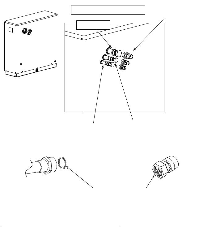
Makeup water, water tank drain and water tank overflow are ½” FPT connections
FIGURE 2-3
VT Lowside Water and Electrical Connections – Rear View
Makeup Water Flow |
VT40 |
VT60 |
VT80 |
VT100 |
Usage - Gallons /100 lbs of Ice |
12 |
12 |
12 |
12 |
Flow rate – Gallons / minute |
0.38 |
0.54 |
0.67 |
0.80 |
Flow rate – Gallons / hour |
22.5 |
32.5 |
40.0 |
48.0 |
Water Tank Capacity – Gallons |
6 |
|
7 |
|
Note: Water usage and flow rates base on 70°F water with no blowdown
TABLE 2-4
MakeUp Water Requirements / Flow Rates

Vogt® VT Service Manual |
2-5 |
|
Installation Instructions |
Wiring And Electrical Connection.
!WARNING !
Only service personnel experienced in refrigeration and qualified to work with high voltage electrical equipment should be allowed to install or work on the Vogt® VT
Series Ice machine.
!WARNING !
Main Power: Power for the entire ice machine will be supplied at the condensing unit.
Refer to the table below to properly size wiring connections. A fused disconnect switch must be provided near the condensing unit of the ice machine. Connect 3 phase power to compressor contactor L1, L2, L3 for operation of the VT ice machine and its controls. If one phase (leg) of the 3 phase power is higher or lower (“Wild”), it should be connected to terminal #L2. Connect the “Ground” wire to the “Ground” terminal provided.
Electrical Data |
VT40 |
VT60 |
VT80 |
|
VT100 |
|
||
Volts/ Phase/ Hertz |
208/230-3-60 |
208/230-3-60 |
208/230-3-60 |
|
460-3-60 |
208/230-3-60 |
460-3-60 |
|
Total F.L.A. |
46.1 |
56.4 |
67.2 |
|
32 |
80.6 |
|
38.7 |
Minimum Circuit Ampacity |
54.0 |
66.9 |
80.4 |
|
38.6 |
97.1 |
|
47 |
Maximum Fuse Size |
85 |
110 |
135 |
|
65 |
165 |
|
80 |
TABLE 2-5
Electrical Requirements
FIGURE 2-4
Main Power Connection
2-6 |
Vogt® VT Service Manual |
Installation Instructions |
|
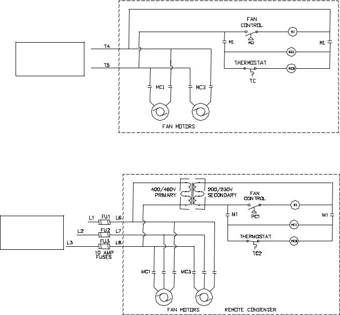
Air Cooled Condenser Wiring: Run two #14 AWG wires from the terminals T4 and T5 on the condensing unit control panel terminal block to the air cooled condenser control panel.
Note: 400/460V VT-80 & VT100’s run 3 #14 AWG wires from terminals L6, L7& L8 to air cooled condenser.
Standard Voltage Machine 200/230V,3PH, 50/60HZ
AIR COOLED |
TO LOWSIDE |
VT-80 & VT-100 |
|
CONDENSER |
|||
|
400/460V, 3PH, 50/60HZ |
||
|
|
||
|
AIR COOLED |
|
|
|
CONDENSER |
TO LOWSIDE |
|
|
|
FIGURE 2-5
Condensing Unit Terminal Blocks
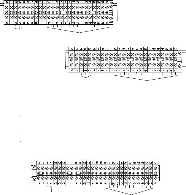
Lowside Electrical Connections: Run 11 #14 AWG or larger wires run from the Lowside control panel terminal block to the condensing unit (highside) control panel terminal block.
Number of wires |
Wire Size (AWG) |
Wire # |
|
5 |
16 (Red) |
1, 2, 3, Y2, Y5 |
|
4 |
16 (Blue) |
X5, X6, X7, 12 |
|
2 |
14 (Black) |
1A, 2A |
|
1 |
14 (Green) |
GND |
|
TABLE 2-6
Lowside to Highside Wire
REMOTE “ON/OFF” |
TO LOWSIDE |
|
SWITCH |
||
|
FIGURE 2-6
Lowside Unit Terminal Block
Note: Machine is supplied with a remote “on/off” connection on the lowside terminal block. If a remote “On/Off” switch is used, remove jumper between #18 & #X1 and connect switch to these terminals.
Vogt® VT Service Manual |
2-7 |
|
Installation Instructions |
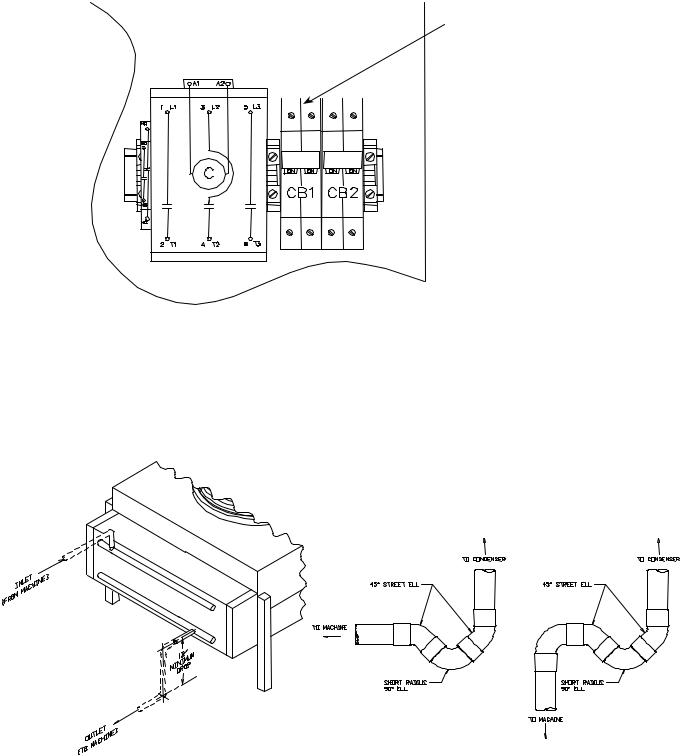
Power is supplied to the lowside through circuit breaker (CB1) located in the condensing unit control panel. See diagram below.
|
|
|
|
|
|
CB1 supplies power |
|
|
|
|
|||
|
Condensing unit control panel |
|
|
to lowside unit |
||
|
|
|
|
|
|
|
|
|
|
|
|
|
|
|
|
|
|
|
|
|
10A 15A
FIGURE 2-7
Condensing Unit Circuit Breakers (200/230V)
Ice making systems with remote condensers are trapped internally. A trap leaving the compressor is not necessary. On vertical runs a short radius “P” trap should be installed every 15’ to 20’ of vertical rise to facilitate oil flow. Horizontal runs should be sloped in direction of refrigerant flow 1” for every 20’ of run. The condenser should be securely mounted in a place capable of sustaining its weight.
FIGURE 2-8
Condenser Piping (VT80 & VT100) and Recommended Traps
2-8 |
|
Vogt® VT Service Manual |
||||
Installation Instructions |
|
|
|
|
|
|
|
|
|
|
|
|
|
|
|
|
|
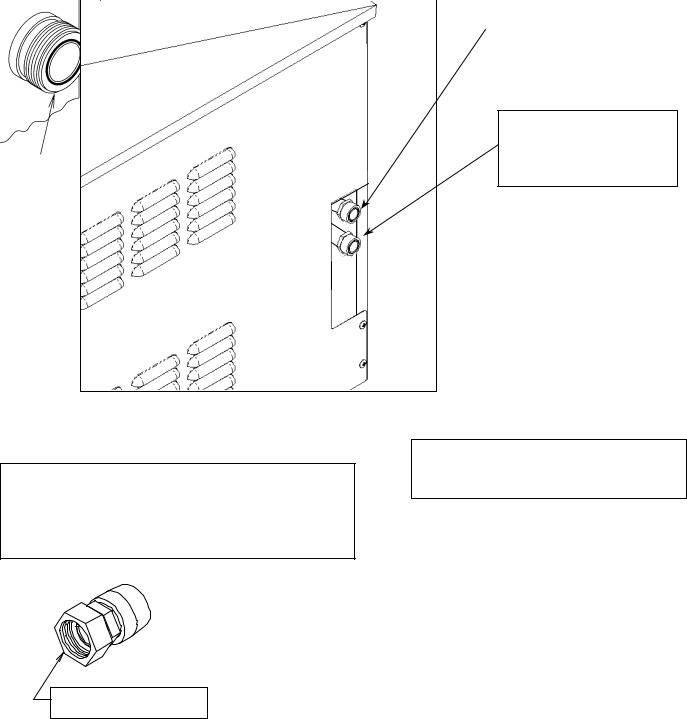
Must solder with 45% silver solder |
||
|
|
|
|
|
|
|
|
|
|
|
|
|
|
|
|
|
|
|
Liquid return from |
|
|
|
|
|
|
Air Cooled Condenser |
|
|
|
|
|
|
(7/8” line) |
|
|
|
|
|
|
|
|
Discharge gas to
Air Cooled Condenser
VT80 - 1 1/8”
VT100 – 1 3/8”
Female Rota-lock Adapters:
12A2396A0701 – for 1 ¼”-12 F x 7/8” Sweat (Solder) (Return Line from condenser)
12A2396A0601 – for 1 ¾”-12 F x 1 3/8” Sweat (Solder) (Discharge to condenser)
Teflon Seal
12A2600T01 (for 1 1/4”-12 thread fitting) 12A2600T03 (for 1 3/4”-12 thread fitting)
Note: Rota-lock male adapter on ice machine
Rota-lock Adapter
Note: Rota-lock adapters supplied with machine
FIGURE 2-10
VT80 & VT100 Condenser Refrigerant Line Connections
Vogt® VT Service Manual |
2-9 |
|
Installation Instructions |
The air cooled condenser will be wired to the condensing unit control panel. Run two #14 AWG wires and a ground wire from the condensing unit control panel to the Air Cooled condenser control panel.
To Ice Machines condensing unit control panel
208/230V
To Ice Machines condensing unit
460V
FIGURE 2-11
VT80 & VT100 Remote Air Cooled Condenser Wiring
Note: Fan control pressure switch is located in air cooled condenser control panel on VT80 & VT100’s with remote condensers. On VT40’s and VT60’s, fan control pressure switch is location on condensing unit (highside).
2-10
Installation Instructions
Vogt® VT Service Manual
Note: Rota-lock fittings
Must solder with 45% silver |
supplied for both lowside |
and highside
Suction Line |
|
|
Hot Gas Line |
Liquid Line |
|
|
|
|
|
|
|
|
FIGURE 2-12
VT Lowside Connections
Rota-lock Fitting |
|
|
|
|
Rota-lock Adapter |
Teflon Seal |
|
|
|||
(on lowside & condensing unit) |
|
|
|
1 3/8” IDS X 1 3/4”-12 Threads |
|
|
|
12A2600T01 (for 1 1/4”-12 thread fitting) |
|
|
1 1/8” IDS X 1 1/4”-12 Threads |
|
|
|
|
||
|
|
12A2600T03 (for 1 3/4”-12 thread fitting) |
|
|
7/8” IDS X 1 1/4”-12 Threads |
|
|
|
|
|
|
|
|
|
|
|
|
|
Rota-lock Adapter |
Teflon Seal |
Where Used |
|
||
Part # |
|
Description |
Part # |
VT40 |
VT60 |
|
12A2396A0501 |
1 1/8” IDS X 1 1/4”-12Thrd |
12A2600T01 |
N/A |
Hot Gas Line |
||
12A2396A0601 |
1 3/8” IDS X 1 3/4”-12Thrd |
12A2600T03 |
Suction Line |
Suction Line |
||
12A2396A0701 |
7/8” IDS X 1 1/4”-12Thrd |
12A2600T01 |
Liquid & Hot Gas line |
Liquid Line |
||
TABLE 2-5
Rota-lock Adapters
Note: See Refrigerant Line Size TABLE 2-3 for line sizes

Vogt® VT Service Manual |
2-11 |
||||||||||||||||||
|
|
|
|
|
|
|
|
|
|
|
|
|
|
|
|
|
|
|
Installation Instructions |
|
|
|
|
|
|
|
|
|
|
|
|
|
|
|
|
|
|
|
|
|
|
|
|
|
|
|
|
|
|
|
|
|
|
|
|
|
|
|
|
|
|
|
|
|
|
|
|
|
|
|
|
|
|
|
|
|
|
|
|
Control Panel
FIGURE 2-13
VT60 Condensing Unit Connections
Control Panel
FIGURE 2-14
VT40 Condensing Unit Connections
2-12 |
Vogt® VT Service Manual |
Installation Instructions |
|
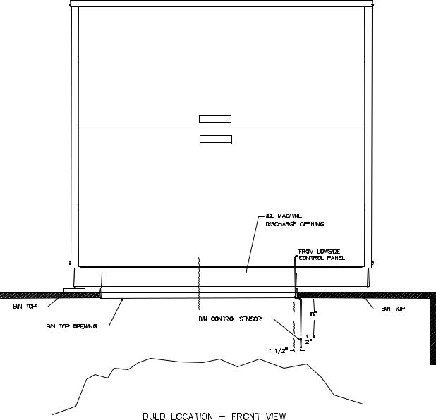
Storing Ice. When storing ice in a bin, make sure the bin control sensor is mounted in the bin properly. The sensor should be mounted on the right side of the bin approximately 8” –12” from the top of the bin.
FIGURE 2-15A
Bin Control Sensor Installation
Vogt® VT Service Manual |
2-13 |
||||||||||||||||
|
|
|
|
|
|
|
|
|
|
|
|
|
|
|
|
|
Installation Instructions |
|
|
|
|
|
|
|
|
|
|
|
|
|
|
|
|
|
|
|
|
|
|
|
|
|
|
|
|
|
|
|
|
|
|
|
|
|
|
|
|
|
|
|
|
|
|
|
|
|
|
|
|
|
|
|
|
|
|
|
|
|
|
|
|
|
|
|
|
|
|
|
|
|
|
|
|
|
|
|
|
|
|
|
|
|
|
|
|
|
|
|
|
|
|
|
|
|
|
|
|
|
|
|
|
|
|
|
|
|
|
|
|
|
|
|
|
|
|
|
|
|
|
|
|
|
|
|
|
|
|
|
|
|
|
|
|
|
|
|
|
|
|
|
|
|
|
|
|
|
|
|
|
|
|
|
|
|
|
|
|
|
|
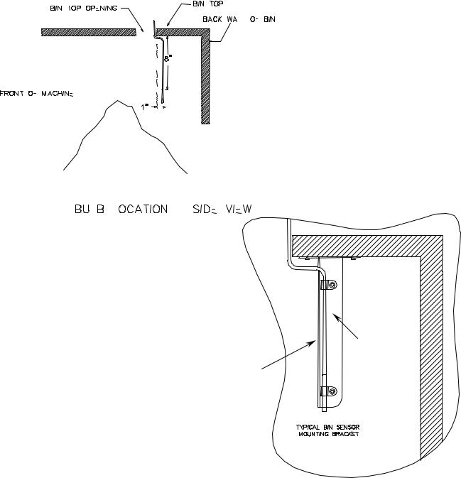
STAINLESS
STEEL
ANGLE
NOTE: Use front of angle to protect probe
FIGURE 2-15B
Bin Control Sensor Installation
Crushed ice weighs approximately 35 pounds per cubic ft. (35 lb/ft3). As ice drops into a bin, it will pile up and slope naturally at about a 45° angle. This natural slope should be taken into account when locating the bin thermostat sensor (or other bin level control) and when calculating the normal bin capacity. If the ice is spread out by hand in the bin for maximum storage capacity, make sure a hazard is not created by allowing ice to back up into the chute and jamming the cutter. Always allow enough room below the chute for at least one harvest.
VT40 = 25-30 lbs. / cycle
VT60 & VT80 = 35-40 lbs. / cycle VT100 = 47-52 lbs. / cycle
2-14 |
Vogt® VT Service Manual |
Installation Instructions
Blank

Vogt® VT Service Manual |
3-1 |
|
Model Specifications |
3.Model Specifications
Electric |
VT-40 |
|
VT-60 |
|
VT-80 |
|
VT-100 |
|
Volts/ Phase/ Hertz |
|
208/230-3-60 |
|
|
|
|||
Total F.L.A. Rating |
46.1 |
|
56.4 |
|
67.2 |
|
80.8 |
|
Minimum Circuit Ampacity |
54.0 |
|
66.9 |
|
80.4 |
|
97.3 |
|
Maximum Circuit Breaker |
90 |
|
110 |
|
135 |
|
165 |
|
Compressor (Copeland® Discus®) |
|
|
|
|
|
|
|
|
Compressor |
5.5 HP |
|
7 HP |
|
10 HP |
|
12.5 HP |
|
Voltage Range (208/230) |
|
|
|
187-253 |
|
|
|
|
Nameplate Amp Rating (RLA) |
31.5 |
|
42.0 |
|
52.6 |
|
66 |
|
Locked Rotor Amp Rating (LRA) |
161.0 |
|
215.0 |
|
278 |
|
374 |
|
Oil (Suniso) – Mineral (R22) |
|
|
|
3GS |
|
|
|
|
Oil (Copeland) – Synthetic (R404A) |
|
Ultra 32 – 3MAF or Mobil EAL Arctic 22 CC |
|
|||||
Oil – amount (Initial Charge / Recharge - oz) |
|
125 / 115 |
|
|
135 / 125 |
|
||
Chopper Motor (Marathon)
HP |
1/2 HP |
|
Voltage |
230 V |
|
FLA |
3.7 A |
|
Water Pump Motor
|
Hartell |
Anjon (CE approved) |
|
HP |
1/12 HP |
1/5 HP (144W) |
|
Voltage |
208-230V |
115V |
|
FLA |
0.85 A |
1.2A |
|
Condenser Fan Motors
HP |
|
|
2 @1/2 HP |
|
|
Voltage |
|
|
208-230 V |
|
|
FLA (Total for both motors) |
8.4 A |
8.2 A |
|
8.4 A |
8.6 A |
Field Connections (Remote Condensing Units Only)
Suction |
1 3/8 ODS |
1 3/8 ODS |
N/A |
N/A |
|
Hot Gas |
7/8 ODS |
1 1/8 ODS |
1 1/8 ODS |
1 1/8 ODS |
|
Liquid |
5/8 ODS |
7/8 ODS |
7/8 ODS |
7/8 ODS |
|
General Info
Sight Glass (Sporlan) |
SA 15U |
SA 17S |
|
SA 17S |
SA 17S |
|
Filter Drier (Sporlan) |
C-415 |
RC-4864 |
|
RC-4864 |
RC-4864 |
|
Refrigerant Charge |
16 lbs. |
32 lbs. |
|
35 lbs. |
40 lbs. |
|
Inlet Water Line |
|
|
½” FPT |
|
|
|
Water Tank Drain & Water Tank Overflow |
|
|
½” FPT |
|
|
|
Control Settings (approximate)
|
R22 |
R404A |
||||
|
Cut-in |
|
Cut-out |
Cut-in |
Cut-out |
|
Fan Switch (PSIG) |
220 |
|
200 |
250 |
|
230 |
Low Pressure Safety (PSIG) |
20 |
|
10 |
20 |
|
10 |
Harvest Hold Pressure Control |
45 |
|
60 |
65 |
|
80 |
High Pressure Safety (PSIG) |
Manual |
|
300 |
Manual |
|
350 |
Oil Pressure Control (Differential) |
|
9 PSIG (Manual Reset) |
|
|||
Listed refrigerant charges are for close coupled and skid mounted machines as tested.
Remote installations of extended length will require additional refrigerant.
Note: Electrical data based on air cooled units

3-2 |
Vogt® VT Service Manual |
Model Specifications |
|
|
Vogt Ice Vertical Tube |
|
Model Number Structure |
|
VT 6 B – P F 26 AC H G 00 |
Basic Model
“VT” – Vertical Tube
|
|
Nominal Capacity |
|
|
|
|
|
|
|
|
|
|
|
|
|
|
|
|
|
|||
|
|
|
|
|
|
|
|
|
|
|
|
|
|
|
|
|
|
|
||||
|
|
in 1000’s of lbs |
|
|
|
|
|
|
|
|
|
|
|
|
|
|
|
|
|
|||
|
|
“4” – 4000 lbs |
|
|
|
|
|
|
|
|
|
|
|
|
|
|
|
|
|
|
||
|
|
“6” – 6000 lbs |
|
|
|
|
|
|
|
|
|
|
|
|
|
|
|
|
|
|
||
|
|
|
|
Revision Level |
|
|
|
|
|
|
|
|
|
|
|
|||||||
|
|
“8” – 8000 lbs |
|
|
|
|
|
|
|
|
|
|
|
|
|
|||||||
|
|
“10” – 10000 lbs |
|
|
A letter assigned to indicate |
|
|
|
|
|
|
|
|
|
|
|
||||||
|
|
|
|
|
|
|
|
|
|
|
|
|
|
|
|
|
|
|||||
|
|
|
|
|
|
|
major revisions within any one |
|
|
|
|
|
|
|
|
|
|
|
||||
|
|
|
|
|
|
|
|
|
|
|
|
|
|
|
|
|
|
|||||
|
|
|
|
|
|
|
family series. |
|
|
|
|
|
|
|
|
|
|
|
||||
|
Configuration |
|
|
|
|
|
|
|
|
|
|
|
|
|
|
|
||||||
|
|
|
|
|
|
|
|
|
|
|
|
|
|
|
|
|
|
|
|
|
||
|
"P" – Package |
|
|
|
|
|
|
|
|
|
|
|
|
|
|
|
|
|
|
|
|
|
|
"L" – Low-side |
|
|
|
|
|
|
|
|
|
|
|
|
|
|
|
|
|
|
|
|
|
|
"H" – High-side |
|
|
Refrigerant |
|
|
|
|
|
|
|
|
|
|
|
|
|
|
|
|
||
|
|
|
|
|
"F" - R22 |
|
|
Electrical Codes |
|
|
|
|
|
|
|
|
|
|
|
|
|
|
|
|
|
|
|
"H" – R404A |
|
|
|
|
Condenser |
|
|
|
|
||||||||
|
|
|
|
|
|
|
"26" - 208/230-3-60 |
|
|
|
|
|
|
|||||||||
|
|
|
|
|
|
|
|
|
|
|
|
|
|
|||||||||
|
|
|
|
|
|
|
|
"46" - 460-3-60 |
|
|
“NC” – No Condenser |
|
|
|
|
|||||||
|
|
|
|
|
|
|
|
"25" - 200-3-50 |
|
|
"AC" – Air Cooled |
|
|
|
||||||||
|
|
|
|
|
|
|
|
"45" - 400-3-50 |
|
|
"WC" – Water Cooled |
|
|
|
||||||||
|
|
|
|
|
|
|
|
|
“35” – 380-3-50 |
|
|
“SW” – Sea Water |
|
|
|
|||||||
|
|
|
|
|
|
|
|
|
|
|
“RC” – Remote Air |
|
|
|
|
|||||||
|
|
|
|
|
|
|
|
|
"21" - 230-1-60 |
|
|
|
|
|
||||||||
|
|
|
|
|
|
|
|
|
|
|
|
|
|
|
|
|
|
|
|
|
||
|
|
|
|
|
|
|
|
|
|
|
|
|
|
|
|
|
|
|
|
|
|
|
|
|
|
|
|
|
|
|
|
|
|
|
|
|
|
|
|
|
|
|
|
|
|
|
|
|
|
|
|
|
|
Compressor Size |
|
|
|
|
|
|
|
|
|
|
|
|||
|
|
|
|
|
|
|
|
|
|
|
|
|
|
|
|
|
|
|
||||
|
|
|
|
|
|
|
|
“0” – No Compressor |
|
|
|
|
|
|
|
|
|
|
|
|||
|
|
|
|
|
|
|
|
“F” – 5 ½HP |
|
|
|
|
|
|
|
|
|
|
|
|||
|
|
|
|
|
|
|
|
“G” – 7HP, 3cyl, 2120 CFH |
|
|
|
|
|
|
|
|
|
|
|
|||
|
|
|
|
|
|
|
|
“H” – 7HP, 4cyl, 2380 CFH |
|
|
|
|
|
|
|
|
|
|
|
|||
|
|
|
|
|
|
|
|
“J” – 10HP |
|
|
|
|
|
|
|
|
|
|
|
|||
|
|
|
|
|
|
|
|
“K” – 12.5HP |
|
|
|
|
|
|
|
|
|
|
|
|||
|
|
|
|
|
|
|
|
|
|
|
Skin (casing) Material |
|
|
|||||||||
|
|
|
|
|
|
|
|
|
|
|
|
|
|
|
|
|
||||||
|
|
|
|
|
|
|
|
|
|
|
|
|
|
|
||||||||
|
|
|
|
|
|
|
|
|
|
|
|
|
|
|
“G” – Galvannealed |
|
|
|||||
|
|
|
|
|
|
|
|
|
|
|
|
|
|
|
“S” – Stainless Steel |
|
|
|||||
|
|
|
|
|
|
|
|
|
|
|
|
|
|
|
|
|
|
|
|
|
|
|
Product Variation Codes (A number or letter designator assigned to specific variations within a family.)
“01” – CE Approved, no skins "00 or Blank" – Standard Product
“NS” – No skins (on condensing unit) “WS” – With skins (on condensing unit) “RS” – Remote Start Switch
 Loading...