


P-24FL
&
P-34FL
TUBE-ICE® MACHINE
Service Manual
$5000
1/17/2006
NOTICE
This manual is the property of the owner of this particular Tube-Ice® machine.
Model #____________________ Serial #____________________.
It is to be left on the premises with this machine at all times. After start-up, it should be stored in a safe place where it can be readily available when needed for future reference in maintaining troubleshooting or servicing.
Failure to comply with this notice will result in unnecessary inconvenience and possible additional expenses.
This manual is intended as an informational tool for the installation, operation, maintenance, troubleshooting, and servicing of this equipment. If an existing situation calls for additional information not found herein, we suggest that you contact your distributor first. If further assistance or information is needed, please feel free to contact the factory at 502-635- 3000 or FAX at 502-635-3024 or 502-634-0479.
IMPORTANT: The Warranty Registration/Start-Up Report found in the front of this manual is to be completed and returned to the factory promptly after the official start-up.
Please return to: |
Vogt Tube Ice LLC. |
|
1000 W. Ormsby Ave. |
|
Suite 19 |
|
Louisville, KY 40210 |
|
Attn. Tube-Ice Service Department |
1/17/2006

Vogt® Tube-Ice® Machine
MID & LARGE MACHINE WARRANTY REGISTRATION/START-UP REPORT
MUST COMPLETE AND RETURN TO INITIATE WARRANTY
Machine Model No. ________________________________ |
Serial No. ____________________________________________ |
|||
Installed at: ____________________________________________________________( |
)_______________________________________ |
|||
Company Name |
Phone |
|
|
|
_______________________________________________________________________________________________________ |
||||
Address |
City |
State |
Zip |
|
______________________________________________________________________________________________________ |
||||
Installed by: ___________________________________________________________( |
)________________________/____/________ |
|||
Company Name |
Phone |
|
Date |
|
_______________________________________________________________________________________________________ |
||||
Address |
City |
State |
Zip |
|
Describe any damage to machine/repairs made: _____________________________________________________________________________
__________________________________________________________________________________________________________________
__________________________________________________________________________________________________________________
Start up by: ___________________________________________________________( |
)________________________/____/_________ |
|
Company Name |
Phone |
Date |
_______________________________________________________________________________________________________
Address
Name of person starting up machine: ____________________________________________________________________________________
PRE START-UP CHECK
CHECK
Service Manual on hand
Machine room suitable 50°F minimum, 110°F maximum
Proper power supply, actual voltage _______________, _________________, _________________ (machine not running)
Compressor crankcase heater on 12 hour minimum
Necessary hand valves opened as required
Solenoid valve stems in auto position
System leak checked/tight
Auxiliary equipment overloads wired into control circuit
Compressor oil level _______ (1/4 glass min.)
All water distributors in place (visually inspected)
Water supply and drain lines installed and connected properly
Compressor, pump, cutter and other motor direction of rotation correct
Make-up water float valve adjusted properly
Hour meter in control panel connected
OPERATION CHECK
Machine charged with refrigerant lbs.______________ Actual voltage ____________ , _______________, ________________(machine running) Ambient temp. _____ °F Fan cycles On _____ Off _____ Tower water in _____°F out ______ °F
Comp motor RLA _____________, _____________, _____________, Actual _____________, _____________, _____________, Pump RLA _____________, _____________, _____________, Actual _____________, _____________, _____________
Cutter motor RLA _____________, _____________, _____________, Actual _____________, _____________, _____________
Suction pressure end of freezing _______, end of harvest _______ Discharge pressure end of freezing ___________, end of harvest __________
Evaporator/suction line frost _____________________________ Receiver liquid level operating ___________________
|
Test |
Water |
FreezeTime |
|
Harvest Time |
First Ice Out |
All Ice Out |
Avg. Hole |
Ice Lb. Per |
Ice Lb. Per |
||
|
Cycle |
Temp |
Min/Sec |
|
Min/Sec |
Min/Sec |
Min/Sec |
Size |
Harvest |
Day |
||
|
#1 |
|
|
|
|
|
|
|
|
|
|
|
|
#2 |
|
|
|
|
|
|
|
|
|
|
|
|
#3 |
|
|
|
|
|
|
|
|
|
|
|
|
#4 |
|
|
|
|
|
|
|
|
|
|
|
Note: Ice lb. per day can be found by: |
|
ice lb. per harvest |
|
x 1440 |
|
|
|
|||||
|
|
|
(freeze time + harvest time) |
|
|
|
|
|||||
The machine operated satisfactorily for ___ continuous hours. Date _______________________________________
Comments__________________________________________________________________________________________________________
__________________________________________________________________________________________________________________
Installer signature ____________________________________________ End user signature _________________________________
Please return to: Vogt Tube Ice LLC, 1000 W. Ormsby, Suite #19, Louisville, KY 40210
1/17/2006

The Vogt Tube Ice LLC., located in
Louisville, Kentucky since 1880.
Sales - (502) 635-3000
Service - (502) 635-3510
Parts - Your Local Distributor
Call your local distributor first for all of your parts and service needs.
Since 1880, Manufacturers of Quality
Tube-Ice® Machines

VOGT®
TUBE-ICE® MACHINES
Installation, Service Manual, and Parts Catalog #12A-4171L13000000
P24FL & P34FL Model
Vogt Tube Ice LLC 1000 W. Ormsby Ave. Suite 19
Louisville, Kentucky 40210 502-635-3000
FAX #502-634-0479
1/17/2006
P24FL & P34FL Service Manual |
i |
TABLE OF CONTENTS
TABLE OF CONTENTS
Vogt® TUBE-ICE® MACHINES
Model P24FL & P34FL
|
Page No. |
1. INTRODUCTION |
|
A Brief History Of Our Company ................................................................................................................................. |
1-1 |
Vogt Energy-Savings Tube-Ice® Machines .................................................................................................................. |
1-1 |
Preview ..................................................................................................................................................................... |
1-1 |
Important Safety Notice................................................................................................................................................. |
1-2 |
Safety Symbols and What They Mean .......................................................................................................................... |
1-2 |
Special Precautions To Be Observed When Charging Refrigeration Systems .............................................................. |
1-3 |
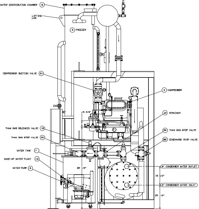
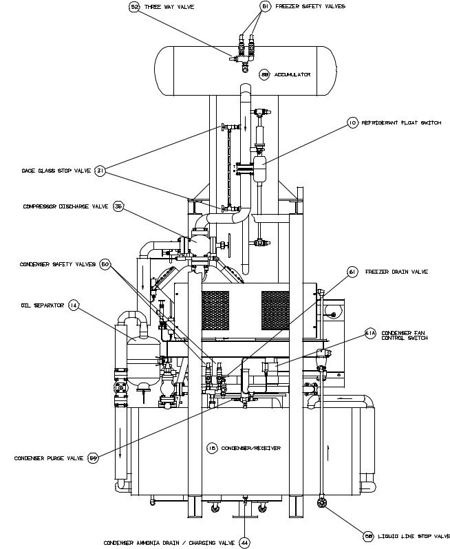
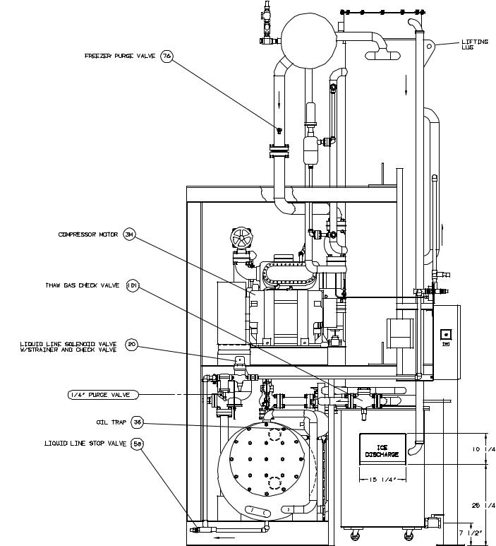
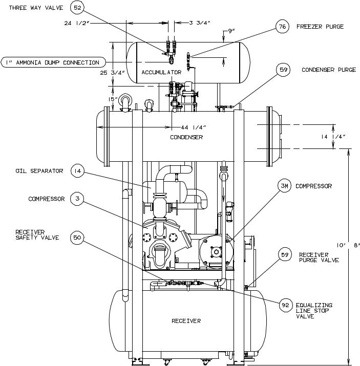
Assembly Drawing Model P24FL Tube-Ice®Machine .................................................................................................. |
1-1, 1-2, 1-3, 1-4 |
Assembly Drawing Model P34AFL Tube-Ice®Machine ............................................................................................... |
1-5, 1-6, 1-7, 1-8 |
2. RECEIPT OF YOUR TUBE-ICE MACHINE |
|
Inspection ..................................................................................................................................................................... |
2-1 |
Description of Machine ................................................................................................................................................. |
2-1 |
Safety Tags and Labels.................................................................................................................................................. |
2-1 |
Model designation for P-Series Ice Machine, Figure 2-1 .............................................................................................. |
2-2 |
Rated Capacity .............................................................................................................................................................. |
2-3 |
Storage (prior to installation and start-up) ..................................................................................................................... |
2-4 |
3. INSTALLING YOUR TUBE-ICE MACHINE |
|
Machine Room .............................................................................................................................................................. |
3-1 |
Space Requirements....................................................................................................................................................... |
3-1 |
Lifting Procedures ......................................................................................................................................................... |
3-1 |
P24FLSpace Diagram, FIGURE 3-1 ............................................................................................................................. |
3-2,3-3 |
P24FL Foundation Layout, FIGURE 3-2 ...................................................................................................................... |
3-4 |
P34FL Space Diagram, FIGURE 3-3 ............................................................................................................................ |
3-5, 3-6 |
P34FL Foundation Layout, FIGURE 3-4 ...................................................................................................................... |
3-7 |
Lifting Procedure for P24FL, FIGURE 3-5.................................................................................................................... |
3-8 |
Lifting Procedure for P34FL, FIGURE 3-6.................................................................................................................... |
3-9 |
Piping and Drain Connections, TABLE 3-1 .................................................................................................................. |
3-10 |
Make-Up Water In,........................................................................................................................................................3-10 |
|
Flushing Water In .......................................................................................................................................................... |
3-10 |
Water Tank Drain .......................................................................................................................................................... |
3-11 |
Water Tank Overflow................................................................................................................................................... |
3-11. |
Safety Valves ................................................................................................................................................................ |
3-11 |
Cooling Tower Piping Diagram, FIGURE 3-7 .............................................................................................................. |
3-12 |
Freeze Protection, FIGURES 3-8, 3-9, 3-10.................................................................................................................. |
3-13, 3-14 |
Wiring and Electrical Connections................................................................................................................................. |
3-14 |
Power Supply Connections, FIGURE 3-11 .................................................................................................................... |
3-15 |
1/17/2006
ii |
P24FL & P34FL Service Manual |
TABLE OF CONTENTS
|
Page No. |
3. INSTALLING YOUR MACHINE (contd) |
|
Voltage Unbalance ......................................................................................................................................................... |
3-15 |
Current Unbalance.......................................................................................................................................................... |
3-15 |
Rotation Check ............................................................................................................................................................... |
3-16 |
Auxiliary Controls or Equipment ................................................................................................................................... |
3-16 |
Installation Review: A Checklist .................................................................................................................................... |
3-17 |
4. HOW YOUR TUBE-ICE MACHINE WORKS |
|
Operating Features......................................................................................................................................................... |
4-1 |
Principle of Operation.................................................................................................................................................... |
4-1 |
Freeze Period................................................................................................................................................................. |
4-1 |
Harvest Period ............................................................................................................................................................... |
4-2 |
Piping Nomenclature ..................................................................................................................................................... |
4-2 |
Piping Schematic for P24FL, FIGURE 4-1 ................................................................................................................... |
4-3 |
Piping Schematic for P34FL, FIGURE 4-2 ................................................................................................................... |
4-4 |
5. START-UP AND OPERATION |
|
Refrigeration System Review ........................................................................................................................................ |
5-1 |
Start-up Checklist .......................................................................................................................................................... |
5-2 |
Refrigerant Charge ........................................................................................................................................................ |
5-2 |
Start-Up ..................................................................................................................................................................... |
5-3 |
Adding Refrigerant ........................................................................................................................................................ |
5-4 |
Operating Tips ............................................................................................................................................................... |
5-5 |
6. ELECTRICAL CONTROLS & THEIR FUNCTIONS |
|
Bin Level Control .......................................................................................................................................................... |
6-1 |
Safety Switches ............................................................................................................................................................. |
6-1 |
Control Panel (Door Opened), FIGURE 6-1.................................................................................................................. |
6-2 |
Description of Control Panel Parts (Inside), TABLE 6-1 .............................................................................................. |
6-2 |
Control Panel (Door Closed), FIGURE 6-2................................................................................................................... |
6-3 |
Description of Control Panel Parts (Outer Door), TABLE 6-2...................................................................................... |
6-3 |
Electrical Schematic All Voltages 50-60 Hz. Across Line Start, FIGURE 6-3 ............................................................. |
6-4 |
Level column wiring for P24FL and P34FL,FIGURE 6-4 ............................................................................................ |
6-5 |
7. MAINTENANCE |
|
Preventive Maintenance................................................................................................................................................. |
7-1 |
Preventative Maintenance Form .................................................................................................................................... |
7-2 |
Ice-Making Section........................................................................................................................................................ |
7-3 |
Cleaning Procedure........................................................................................................................................................ |
7-3 |
Water Distributors, TABLE 7-1 .................................................................................................................................... |
7-3 |
Average Hole Size in Tube-Ice®, TABLE 7-2............................................................................................................... |
7-4 |
Water Tank .................................................................................................................................................................... |
7-4 |
Cutter Gear Reducer ...................................................................................................................................................... |
7-5 |
P24FL & P34FL Service Manual |
iii |
|
TABLE OF CONTENTS |
8. TROUBLESHOOTING |
Page No. |
|
|
List Of Symptoms.......................................................................................................................................................... |
8-1 |
Machine Stopped ........................................................................................................................................................... |
8-2, 8-3 |
Freeze-Up Due To Extended Freezing Period ............................................................................................................... |
8-4 |
Freeze-Up Due To Ice Failing To Discharge................................................................................................................. |
8-5 |
Low Ice Capacity........................................................................................................................................................... |
8-6, 8-7 |
Poor Ice Quality............................................................................................................................................................. |
8-7 |
High Discharge Pressure................................................................................................................................................ |
8-8 |
Low Discharge Pressure ................................................................................................................................................ |
8-9 |
High Suction Pressure.................................................................................................................................................... |
8-9 |
Compressor Running Unloaded During Freeze ............................................................................................................. |
8-9 |
Compressor Oil Pressure Low ....................................................................................................................................... |
8-10 |
Compressor Loosing Oil Excessively............................................................................................................................ |
8-10 |
Machine Short Cycles.................................................................................................................................................... |
8-11 |
Shut Down By Oil Pressure Switch ............................................................................................................................... |
8-11 |
High Compressor Discharge Temperature..................................................................................................................... |
8-11 |
Suction Line Frosting To Compressor ........................................................................................................ |
8-12 |
9. SERVICE OPERATIONS |
|
Automatic Blow down (Harvest Cycle)......................................................................................................................... |
9-1 |
Cleaning the Ice Making Section................................................................................................................................... |
9-1 |
Float Valve (Make-Up Water)....................................................................................................................................... |
9-1 |
Capacitive Level Control............................................................................................................................................... |
9-1 |
Troubleshooting Guide the level controller, TABLE 9-1 .............................................................................................. |
9-5 |
Hand Expansion Valve .................................................................................................................................................. |
9-6 |
Freezer Pressure Switch................................................................................................................................................. |
9-6 |
Freezer Pressure Switch, FIGURE 9-2 .......................................................................................................................... |
9-6 |
High/Low Pressure Switch ............................................................................................................................................ |
9-6 |
High/Low Pressure Switch, FIGURE 9-3...................................................................................................................... |
9-7 |
Control Circuit Protection.............................................................................................................................................. |
9-7 |
Thawing Timer .............................................................................................................................................................. |
9-7 |
Thawing Timer, FIGURE 9-4........................................................................................................................................ |
9-8 |
P24FL and P34FL Cutter Assembly, FIGURE 9-5A..................................................................................................... |
9-8 |
P24F and P34FL Water Tank Assembly, FIGURE 9-5B .............................................................................................. |
9-9 |
P24FL and P34FL Cutter and Water Tank Part No., TABLE 9-2 ................................................................................. |
9-9, 9-10 |
Cutter Gear Reducer ...................................................................................................................................................... |
9-10 |
Drive Gear Replacement................................................................................................................................................ |
9-11 |
Gear Reducer Replacement ........................................................................................................................................... |
9-12, 9-13 |
Water Tank and Cutter Parts Weights, TABLE 9-3 ...................................................................................................... |
9-13 |
Water Tank Removal..................................................................................................................................................... |
9-13 |
Cutter Assembly Removal and Installation ................................................................................................................... |
9-14 |
Bearing Bracket and Cutter Disc Removal.................................................................................................................... |
9-14 |
Cutter Shaft and Bearing Removal ................................................................................................................................ |
9-15 |
1/17/2006
iv |
P24FL & P34FL Service Manual |
TABLE OF CONTENTS
9. SERVICE OPERATIONS (contd) |
Page No. |
|
|
Cutter Shaft and Bearing Installation............................................................................................................................. |
9-15, 9-16 |
Cutter Height Adjustment.............................................................................................................................................. |
9-16 |
Water Tank Installation ................................................................................................................................................. |
9-17 |
Cutter Ring Gear Replacement ...................................................................................................................................... |
9-18 |
Cutter Blade Replacement ............................................................................................................................................. |
9-18 |
Cutter Blade and Adapter Plate Adjustment, FIGURE 9-6 ........................................................................................... |
9-18 |
Cutter Adapter Plate Installation.................................................................................................................................... |
9-19 |
Pumpdown9-19, 9-20 |
|
Removal of Refrigerant from the Machine .................................................................................................................... |
9-20 |
Refrigerant Leaks .......................................................................................................................................................... |
9-20 |
Non-Condensable Gases................................................................................................................................................ |
9-20. |
Water Contamination of R-22 Refrigerant.................................................................................................................... |
9-20 |
Circulating Water Pump Motor ..................................................................................................................................... |
9-21 |
The Thaw Gas Solenoid Valve ...................................................................................................................................... |
9-21 |
Thaw Gas Solenoid Valve, FIGURE 9-7....................................................................................................................... |
9-22 |
The Liquid Feed A1 and A2 Solenoid Valves ............................................................................................................... |
9-22 |
The Liquid Feed Solenoid Valve, FIGURE 9-8............................................................................................................. |
9-23 |
Water Flush Solenoid Valve .......................................................................................................................................... |
9-23 |
10. OPTIONS AND ACCESSORIES |
|
Crushed Ice Production ................................................................................................................................................. |
10-2 |
Length of Ice ................................................................................................................................................................. |
10-2 |
Power Monitor .............................................................................................................................................................. |
10-3 |
11. TABLES AND CHARTS |
|
P24FL Specifications, TABLE 11-1............................................................................................................................ |
11-2 |
P34FL Specifications, TABLE 11-2............................................................................................................................ |
11-3 |
P24FL Capacity Ratings, TABLE 11-3 A ................................................................................................................... |
11-4 |
P34FL Capacity Ratings, TABLE 11-3 B ................................................................................................................... |
11-5 |
P24FL Condenser Water Usage, TABLE 11-4............................................................................................................ |
11-6 |
P34FL Condenser Water Usage, TABLE 11-5............................................................................................................ |
11-6 |
P24FL Make-Up Water Usage, TABLE 11-6.............................................................................................................. |
11-7 |
P34FL Make-Up Water Usage, TABLE 11-7.............................................................................................................. |
11-7 |
P24FL Normal Operating Vitals, TABLE 11-8........................................................................................................... |
11-8 |
P24FL Normal Operating Vitals, TABLE 11-9........................................................................................................... |
11-8 |
Temperature Pressure Chart, TABLE 11-10................................................................................................................ |
11-10 |
Conversion Factors: English to Metric, TABLE11-11 ................................................................................................ |
11-11 |
Constants, TABLE 11-12 ............................................................................................................................................ |
11-11 |
12. APPENDIX |
|
P24FL & P34FL Service Manual |
v |
TABLE OF CONTENTS
1/17/2006
P24FL & P34FL Service Manual |
1-1 |
|
INTRODUCTION |
1. Introduction
Henry Vogt Machine Co.
A Brief History Of Our Company. shop in Louisville, Kentucky in 1880. producers of ice-making equipment.
Henry Vogt Machine Co. was founded as a small machine Today, Vogt Tube Ice LLC is one of the world’s leading
In 1938, Vogt built the first Tube-Ice® machine and revolutionized the ice-making industry. Our first “sized-ice” machine quickly replaced the old can-ice plants, which required hard labor and large amounts of floor space for freezing, cutting, and crushing ice by hand.
Vogt Energy-Saving Tube-Ice Machines Are Cost Effective. Today, Vogt Tube-Ice® machines enjoy a well-earned reputation as the most energy efficient, dependable ice-making equipment in the world.
Using as little as one-half to one-third the energy required by competitors’ ice makers, Tube-Ice® machines produce the same amount of ice--in restaurants, sports arenas, packing plants, and wholesale operations around the globe--at great savings.
In addition, Tube-Ice® machines are renowned for their long life, giving many customers more than 35 years of dependable service. Ask someone who owns one.
Preview. All the skill in engineering and fabrication that we’ve learned in over a century of experience is reflected in every Tube-Ice® machine. Since Vogt introduced Tube-Ice® machines in 1938, the process of making Tube-Ice® ice has been widely recognized as the most economical means of production. The machine’s economic and reliable operation has been proven over and over again, in a network of varied types of installations throughout the world.
Furnished with your machine is the Certificate Of Test--the report of operating data which is a record of the unit’s satisfactory operation at our factory test floor. It is evidence of our desire to deliver to you “the finest ice-making unit ever made.”
This manual is designed to assist you in the installation, start-up, and maintenance of your unit. Your Tube-Ice® machine will give you a lifetime of service provided you install, maintain, and service it properly.
Please read your manual carefully before attempting installation, operation, or servicing of this professionally designed piece of equipment. Also, make sure the Warranty Registration/Start-up Report is completed and returned.
If you have additional questions, please call your distributor. Also, feel free to phone the factory direct at (502) 635-3000.
9/15/09

1-2 |
P24FL & P34FL Service Manual |
INTRODUCTION
Important Safety Notice. This information is intended for use by individuals possessing adequate backgrounds in electrical, refrigeration and mechanical experience. Any attempt to repair major equipment may result in personal injury and /or property damage. The manufacturer or seller cannot be responsible for the interpretation of this information, nor can it assume any liability in connection with its use. It is important that personnel understand the properties of this refrigerant and that they be thoroughly trained in safe practices for its use and handling. Refer to the enclosed “Freon Compounds and Safety” in Appendix A.
Safety Symbols & What They Mean. Prior to installation or operation of the Tube-Ice® machine, please read this manual. Are you familiar with the installation, start-up, and operation of a TubeIce® machine? Before you operate, adjust or service this machine, you should read this manual, understand the operation of this machine, and be aware of possible dangers.
These safety symbols will alert you
when special care is needed.
Please heed them.
!DANGER !
Indicates an immediate hazard and that special precautions are necessary to avoid severe personal injury or death.
! DANGER !
!WARNING !
Indicates a strong possibility of a hazard and that an unsafe practice could result in severe personal injury.
! WARNING !
!CAUTION !
Means hazards or unsafe practices could result in personal injury or product or property damage.
! CAUTION !
9/15/09

P24FL & P34FL Service Manual |
1-3 |
|
INTRODUCTION |
Special Precautions To Be Observed When Charging Refrigeration Systems. Only technically qualified persons, experienced and knowledgeable in the handling of R-22 or R-404a refrigerants, and the operation of refrigeration systems, should perform the operations described in this manual. All local, federal, and EPA regulations must be strictly adhered to when handling R-22 or R-404a refrigerants. See “Material Safety Data Sheet”, MSDS Code No. DU000025 (R-22) or MSDS Code No. DU005612 (R-404a) in Appendix A. For further information concerning refrigerants and handling practices see internet web site: www.dupont.com/suva/
If a refrigeration system is being charged from refrigerant cylinders, disconnect each cylinder when empty or when the system is fully charged. A gage should be installed in the charging line to indicate refrigerant cylinder pressure. The cylinder may be considered empty of liquid refrigerant when the gauge pressure is 25 pounds or less, and there is no frost on the cylinder. Close the refrigerant charging valve and cylinder valve before disconnecting the cylinder. Loosen the union in the refrigerant charging line--carefully to avoid unnecessary, excessive or illegal release of refrigerant into the atmosphere.
!CAUTION !
Immediately close system charging valve at commencement of defrost or thawing cycle if refrigerant cylinder is connected. Never leave a refrigerant cylinder connected to system except during charging operation. Failure to observe either of these precautions can result in transferring refrigerant from the system to the refrigerant cylinder, over-filling it, and possibly causing the cylinder to rupture because of pressure from expansion of the liquid refrigerant brought on by an increase in temperature.
!CAUTION !
Always store cylinders containing refrigerant in a cool place. They should never be exposed to temperatures higher than 120 F (R-22) or 108 F (R-404a), and should be stored in a manner to prevent abnormal mechanical shocks.
Also, transferring refrigerant from a refrigeration system into a cylinder can be very dangerous and is not recommended.
!CAUTION !
It is not recommended that refrigerant be transferred from a refrigeration system directly into a cylinder. If such a transfer is made, the refrigerant cylinder must be an approved, CLEAN cylinder--free of any contaminants or foreign materials--and must be weighed continuously to assure contents do not exceed net weight specified by cylinder manufacturer or any applicable code requirements.
! CAUTION !
9/15/09

1-4 |
P24FL & P34FL Service Manual |
INTRODUCTION
FIGURE 1-1
P24FL Front Side (Control Panel)
9/15/09
P24FL & P34FL Service Manual |
1-5 |
INTRODUCTION
FIGURE 1-2 |
9/15/09
1-6
INTRODUCTION
P24FL & P34FL Service Manual
FIGURE 1-3 |
P24FL Back Side |
9/15/09
P24FL & P34FL Service Manual |
1-7 |
|
INTRODUCTION |
|
FIGURE 1-4 |
|
P24FL Left Side |
9/15/09
1-8
INTRODUCTION
P24FL & P34FL Service Manual
FIGURE 1-5 |
P34FL Front Side |
9/15/09

P24FL & P34FL Service Manual
FIGURE 1-6 |
P34FL Right Side |
1-9
INTRODUCTION
9/15/09
1-10 |
P24FL & P34FL Service Manual |
INTRODUCTION
FIGURE 1-7 |
P34FL Back Side |
9/15/09

P24FL & P34FL Service Manual |
FIGURE 1-8
P34FL Left Side (Control Panel)
1-11
INTRODUCTION
9/15/09
1-12 |
P24FL & P34FL Service Manual |
INTRODUCTION
9/15/09

P24FL & P34FL Service Manual |
2-1 |
|
RECEIPT OF YOUR TUBE-ICE MACHINE |
|
2. Receipt Of Your Tube-Ice Machine |
!CAUTION !
Only service personnel experienced in refrigeration systems and qualified to work on high amperage electrical equipment should be allowed to install or service this Tube-Ice machine.
Eye protection should be worn by all personnel working on or around the Tube-Ice machine.
It is very important that you are familiar with and adhere to all local, state, and federal, etc. ordinances and laws regarding the handling, storing, and use of R-22 refrigerant.
An approved refrigerant mask should be readily available for use in an emergency and all personnel should be aware of its location and proper use.
!CAUTION !
Inspection. As soon as you receive your machine, inspect it for any damage. If damage is suspected, note it on the shipper’s papers (i.e., the trucker’s Bill of Lading). Immediately make a separate written request for inspection by the freight line’s agent. Any repair work or alteration to the machine without the permission of Tube-Ice LLC can void the machine’s warranty. You should also notify your Vogt distributor or the factory.
Description Of Machine. A Vogt low side Tube-Ice machine is a remote ice producing plant requiring refrigerant suction connection, refrigerant liquid connection, thaw gas connection, makeup water supply, electrical connection, and the proper refrigerant charge.
The machine has been partially factory tested prior to shipment and will require adjustment to meet the high side (condensing unit) operating conditions. See Start-up and Operation for the correct setting of the controls.
After factory pressure testing of the machine, the machine is evacuated and charged with nitrogen gas pressure for shipment. This prevents air or moisture from entering the system during transit. There should be a positive pressure (20-25 psig) indicated on the control panel gages when the machine is received. The machine has been cleaned with ice machine cleaner and flushed so that the machine is ready for ice production.
Safety Tags and Labels. Be sure to read and adhere to all special tags and labels attached to valves or applied to various areas of the machine. They provide important information necessary for safe and efficient operation of your equipment.
The machine is available in three different tube sizes for producing ice 7/8” OD x 1” long, 1 1/8” OD x 1” long, or 1 3/8” OD x 1” long. The ice is cut to length by a rotating breaker type cutter. Ice can be produced up to 1 1/2” long by modifying the spacers under the adapter plates (see Chapter 10, “Ice Length” for modifying instructions). Crushed ice is also available by modifying the cutter and making minor adjustments to the machine (see Chapter 10, “Crushed Ice”)
9/15/09

2-2 |
P24FL & P34FL Service Manual |
|
RECEIPT OF YOUR TUBE-ICE MACHINE
50T A L F B 5 46 NC 000
Nominal Capacity
(“T”= tons/day) “25T” – 25 tons/day “50T” – 50 tons/day “80T” – 80 tons/day
Model Variation
A letter assigned to indicate major variations within any one family series
Basic Configuration
“P” – Package
“L” - Lowside
Refrigerant
“F” – R-22
“A” – Ammonia
“H” – R-404a
Type of Ice
“B” – Cylinder
“K” – Crushed
“L” – 1 ½” Long Ice
Product Variation Code
A number or letter designator assigned to specific variations within a family series
“000 or Blank” – Standard Product
Consult factory for specific code interpretation
Condenser Type
“WC” – Water Cooled
“NC” – No Condenser
Electrical Codes
“26” – 208/230-3-60 “46” – 460-3-60 “25” – 200-3-50 “45” – 400-3-50
Tube Size
(In ¼’s of an inch) “4” – 1” “5” – 1 ¼” “6” – 1 ½” “7” – 1 ¾” “8” – 2”
FIGURE 2-1
Model Designation for P-Series Ice Machines
Rated Capacity. The Tube-Ice machine is rated to produce a given amount of ice when operating under the proper conditions as specified in this manual. You should be prepared to handle the ice produced as it is discharged from the machine and move it to your storage or bagging area promptly. The following specifications are given to help you do just that.
9/15/09

P24FL & P34FL Service Manual |
|
|
|
|
|
2-3 |
||||||
|
|
|
|
|
|
|
RECEIPT OF YOUR TUBE-ICE MACHINE |
|||||
|
|
|
|
|
|
|
Model P24FL-1” |
|
|
|||
|
|
|
Model P24FL-1.5” |
Model P24FL-1.25” |
|
|||||||
|
|
Makeup Water |
Capacity Tons/day |
|
Makeup |
|
Makeup |
|
|
Makeup |
|
|
|
|
|
Water |
Capacity Tons/day |
Water |
Capacity Tons/day |
|
Water |
|
|
||
|
|
Temp. |
(2000 lbs/24 hours) |
|
GPM |
(2000 lbs/24 hrs.) |
GPM |
(2000 lbs/24 hours) |
|
GPM |
|
|
|
|
85 F/29 C |
21.4 |
|
4.46 |
21.5 |
4.48 |
20.8 |
|
4.33 |
|
|
|
|
80 F/24 C |
21.9 |
|
4.57 |
22.6 |
4.71 |
21.7 |
|
4.53 |
|
|
|
|
75 F/23 C |
22.5 |
|
4.69 |
23.2 |
4.83 |
22.3 |
|
4.64 |
|
|
|
|
70 F/21 C |
23.1 |
|
4.81 |
23.8 |
4.95 |
22.8 |
|
4.76 |
|
|
|
|
65 F/18 C |
23.7 |
|
4.94 |
24.4 |
5.09 |
23.4 |
|
4.88 |
|
|
|
|
60 F/15 C |
24.3 |
|
5.07 |
25.1 |
5.23 |
24.0 |
|
5.00 |
|
|
|
|
55 F/13 C |
25.0 |
|
5.70 |
25.8 |
5.37 |
24.7 |
|
5.14 |
|
|
|
|
|
|
|
|
|
|
|
||||
|
|
Ice lb/harvest |
750 lbs/340 Kg |
|
600 lbs/272 Kg |
450 lbs/204 Kg |
|
|
||||
|
|
|
|
|
6,000 lbs/2,720 Kg |
|
|
|||||
|
|
Shipping |
5,800lbs/2,630 Kg |
6,200 lbs/2,810 Kg |
|
|
||||||
|
|
weight (without |
|
|
|
|
|
|
|
|
|
|
|
|
charge) |
|
|
|
|
|
7,500 lbs/3,400 Kg |
|
|
||
|
|
Operating |
7,150lbs/ 3,240 Kg |
7,700 lbs/ 3,450 Kg |
|
|
||||||
|
|
weight |
|
|
|
|
|
|
|
|
|
|
|
|
|
|
|
Model P34FL-1” |
|
|
|||||
|
|
|
Model P34FL-1.5” |
Model P34FL-1.25” |
|
|||||||
|
|
Makeup Water |
Capacity Tons/day |
|
Makeup |
|
Makeup |
|
|
Makeup |
|
|
|
|
|
Water |
Capacity Tons/day |
Water |
Capacity Tons/day |
|
Water |
|
|
||
|
|
Temp. |
(2000 lbs/24 hours) |
|
GPM |
(2000 lbs/24 hrs.) |
GPM |
(2000 lbs/24 hours) |
|
GPM |
|
|
|
|
|
|
|
|
|
|
|
|
|
|
|
|
|
85 F/29 C |
45.8 |
|
12.7 |
48.8 |
13.7 |
45.6 |
|
13.4 |
|
|
|
|
80 F/24 C |
46.8 |
|
13.0 |
49.9 |
14.0 |
46.6 |
|
13.8 |
|
|
|
|
75 F/23 C |
47.8 |
|
13.4 |
51 |
14.4 |
47.6 |
|
14.2 |
|
|
|
|
70 F/21 C |
48.8 |
|
13.7 |
52.1 |
14.7 |
48.6 |
|
14.5 |
|
|
|
|
65 F/18 C |
49.8 |
|
14.1 |
53.2 |
15.1 |
49.6 |
|
14.9 |
|
|
|
|
60 F/15 C |
50.8 |
|
14.4 |
54.3 |
15.4 |
50.6 |
|
15.2 |
|
|
|
|
55 F/13 C |
51.8 |
|
14.8 |
55.4 |
15.8 |
51.6 |
|
15.6 |
|
|
|
|
|
|
|
|
|
|
|
|
|||
|
|
Ice lb/harvest |
1728lbs/785 Kg |
|
1414lbs/642 Kg |
998lbs/453 Kg |
|
|
|
|||
|
|
|
|
|
9,600 lbs /4,350 Kg |
|
|
|||||
|
|
Shipping weight |
9,600lbs / 4350 Kg |
10,000lbs / 4,530 Kg |
|
|
||||||
|
|
|
|
|
10,450lbs/4,740 Kg |
|
|
|||||
|
|
Operating weight |
11,200 lbs/ 5,080 Kg |
11,400 lbs/ 5,170 Kg |
|
|
||||||
|
|
|
|
|
|
|
|
|
|
|
|
|
Notes:
1.Makeup water is average flow and includes 25% blow down. Peak flow rate is 15 GPM. at 40 PSI minimum. When water quality is good, machine can be operated with 5% to 10% blow down.
2.Ratings are at 90 F ambient for ice machine.
3.Capacity ratings are based on 85 F water entering condenser. For entering water temperatures above 85 F, deduct 4% in capacity for each 5 F.
4.Capacity shown is the average for model. Individual machines may vary up to 5% above or below depending on field conditions.
TABLE 2-1
P24FL & P34FL Specifications
Storage (prior to installation or start-up). The machine must not be stored or installed in an area that is subject to reach temperatures at or above 110 F (43.3 C). Temperatures above this may cause the relief valves to open and result in the loss of refrigerant.
9/15/09
2-4 |
P24FL & P34FL Service Manual |
|
RECEIPT OF YOUR TUBE-ICE MACHINE
9/15/09

P24FL & P34FL Service Manual |
3-1 |
|
INSTALLING YOUR TUBE ICE MACHINE |
3. Installing Your Tube-Ice Machine
Your machine will be shipped to you as one package. You will need to arrange for the handling of the package as soon as it arrives, see the machine specifications Table 2-1 for shipping and operating weight. Before you remove the unit from the truck, be certain that any sign of damage, however slight, is noted on the carrier’s papers.
Note: See “Lifting Procedure” drawing furnished with this manual, Fig 3-5 and 3-6.
Machine Room. The machine must be located inside a suitable building and must not be subjected to ambient temperatures below 50 F (10 C) or above 110 F (43.3 C). Heat radiation from other sources (sunlight, furnaces, condenser, etc.) and unusual air current may affect the operation of the machine and should be avoided. The electrical components of the Tube-Ice® machine are rated
NEMA 1. Therefore, the machine should not be located in a hazardous area or sprayed with water. The machine should be installed in an area where water will not stand, but will readily drain away from the machine.
Space Requirements. Refer to the space diagrams, Figures 3-1 and 3-3, for recommended minimum clearance around the machine for ease of servicing and observation. Pay particular attention to the additional space required. If it ever becomes necessary to mechanically clean the condenser tubes, extra space will be required on one end (preferably on the opposite end from the water inlet and outlet) for the cleaning tools.
Foundation. Refer to the space diagrams, Figures 3-2 and 3-5, for recommended minimum foundation requirements. The figures show anchor bolt details and machine anchor hole details. Contact your local distributor for seismic anchoring requirements in your area.
!WARNING !
Lifting or moving heavy equipment should only be attempted by competent rigging and hoisting contractors. Never allow personnel near or under heavy equipment when it is being moved or lifted. Failure to comply could result in personal injury or loss of life.
!WARNING !
Lifting Procedures. Your Tube-Ice machine is provided with lifting lugs for the purpose of unloading and moving the machine to its operation location. Refer to the enclosed drawings for instructions and illustrations of their use.
P24FL - Figure 3-5. Machine weight 6,200 lbs.
P34FL - Figure 3-6. Machine weight 10,000 lbs.
These figures are intended as a guide to unloading and lifting the P24FLand P34FL Tube-Ice® machine. The Vogt Tube Ice LLC. is not responsible for product damage or personnel injury or loss of life during the loading or lifting procedure.
9/15/09
 Loading...