

Page 1

P-42AL
TUBE-ICE®
MACHINE
Service Manual
$5000
9/30/10
Page 2

NOTICE
This manual is the property of the owner of this particular Tube-Ice®
machine.
Model #____________________ Serial #____________________.
It is to be left on the premises with this machine at all times. After start-up,
it should be stored in a safe place where it can be readily available when
needed for future reference in maintaining troubleshooting or servicing.
Failure to comply with this notice will result in unnecessary inconvenience
and possible additional expenses.
This manual is intended as an informational tool for the installation,
operation, maintenance, troubleshooting, and servicing of this equipment.
If an existing situation calls for additional information not found herein, we
suggest that you contact your distributor first. If further assistance or
information is needed, please feel free to contact the factory at 502-6353000 or FAX at 502-635-3024 or 502-634-0479.
IMPORTANT: The Warranty Registration/Start-Up Report found in the
front of this manual is to be completed and returned to the factory promptly
after the official start-up.
Please return to: Tube Ice, LLC
1000 W. Ormsby, Suite 19
Louisville, KY 40210
Att. Tube-Ice Service Department
Page 3
9/30/10
MID & LARGE MACHINE WARRANTY REGISTRATION/START-UP REPORT
Vogt® Tube-Ice® Machine
MUST COMPLETE AND RETURN TO INITIATE WARRANTY
Machine Model No. ________________________________ Serial No. ____________________________________ ________
Installed at: ____________________________________________________________( )_________ ______________________________
Company Name Phone
_________________________________________________ ______________________________________________________
Address City State Zip
______________________________________________________________________________________________________
Installed by: ___________________________________________________________( )___________ _____________/____/________
Company Name Phone Date
_______________________________________________________________________________________________________
Address City State Zip
Describe any damage to machine/repairs made: _____________________________________________________________________________
__________________________________________________________________________________________________________________
__________________________________________________________________________________________________________________
Start up by: ___________________________________________________________( )________________________/____/_________
Company Name Phone Date
_______________________________________________________________________________________________________
Address
Name of person starting up machine: ____________________________________________________________________________________
PRE START-UP CHECK
CHECK
Service Manual on hand
Machine room suitable 50°F minimum, 110°F maximum
Proper power supply, actual voltage _______________, _________________, _________________ (machine not running)
Compressor crankcase heater on 12 hour minimum
Necessary hand valves opened as required
Solenoid valve stems in auto position
System leak checked/tight
Auxiliary equipm ent overloads wired into control circuit
Compressor oil level _______ (1/4 glass min.)
All water distributors in place (visually inspected)
Water supply and drain lines installed and connected properly
Compressor, pump, cutter and other motor direction of rotation correct
Make-up water float valve adjusted properly
Hour meter in control panel connected
OPERATION CHECK
Machine charged with refrigerant lbs.______________ Actual voltage ____________ , _______________, ________________(machine running)
Ambient temp. _____ °F Fan cycles On _____ Off _____ Tower water in _____°F out ______ °F
Comp motor RLA _____________, _____________, ______ _______, Actual _____________, _____________, _____________,
Pump RLA _____________, _____________, _____________, Actual _____________, _____________, ________ _____
Cutter motor RLA _____________, _____________, ______ _______, Actual _____________, _____________, ______ _______
Suction pressure end of freezing _______, end of harvest _______ Discharge pressure end of freezing ___________, end of harvest __________
Evaporator/suction line frost _____________________________ Receiver liquid level operating ___________________
Test
Cycle
Water
Temp
FreezeTime
Min/Sec
Harvest Time
Min/Sec
First Ice Out
Min/Sec
All Ice Out
Min/Sec
Avg. Hole
Size
Ice Lb. Per
Harvest
Ice Lb. Per
Day
#1
#2
#3
#4
Note: Ice lb. per day can be found by:
(freeze time + harvest time)
ice lb. per harvest x 1440
The machine operated satisfactorily for ___ continuous hours. Date _______________________________________
Comments__________________________________________________________________________________________________________
__________________________________________________________________________________________________________________
Installer signature ____________________________________________ End user signature _________________________________
Please return to: Tube Ice LLC, 1000 W. Ormsby, Suite #19, Louisville, KY 40210
Page 4

®
VOGT
TUBE-ICE® MACHINES
P42AL Model
Tube Ice, LLC
1000 W. Ormsby Avenue, Suite 19
Louisville, Kentucky, 40210
800-853-8648 • 502-635-3000
Fax: 502-634-0479
Page 5

TABLE OF CONTENTS
Page No.
1. INTRODUCTION
A Brief History Of Our Company..................................................................................................................................1-1
Vogt Energy-Savings Tube-Ice® Machines..................................................................................................................1-1
Preview .....................................................................................................................................................................1-1
Important Safety Notice.................................................................................................................................................1-2
Safety Symbols and What They Mean...........................................................................................................................1-2
Special Precautions To Be Observed When Charging Refrigeration Systems...............................................................1-3
Assembly Drawing Model P42AL Tube-Ice
2. RECEIPT OF YOUR TUBE-ICE MACHINE
Inspection .....................................................................................................................................................................2-1
Description of Machine .................................................................................................................................................2-1
Safety Tags and Labels..................................................................................................................................................2-1
Model designation for P-Series Ice Machine, Figure 2-1...............................................................................................2-2
Storage (prior to installation and s tart-up).....................................................................................................................2-2
3. INSTALLING YOUR TUBE-ICE MACHINE
Machine Room ..............................................................................................................................................................3-1
Space Requirements.......................................................................................................................................................3-1
Foundation .....................................................................................................................................................................3-1
Lifting Procedures .........................................................................................................................................................3-1
P42AL Foundation Layout, FIGURE 3-1...................................................................................................................... 3-2
Lifting Procedure for P42AL, FIGURE 3-2..................................................................................................................3-3
Seismic Anchoring Detail, FIGURE 3-3 .......................................................................................................................3-4
Water Supply, Drain and Refrigeration Connections, TABLE 3-1................................................................................3-5
Make-Up Water In,........................................................................................................................................................3-5
Flushing Water In..........................................................................................................................................................3-5
Water Tank Drain..........................................................................................................................................................3-6
Water Tank Overflow.....................................................................................................................................................3-6
Receiver .....................................................................................................................................................................3-6
Receiver Volume Requirements, TABLE 3-2 ...............................................................................................................3-6
Suction Pressure Regulator............................................................................................................................................3-6
Compressor Unloading..................................................................................................................................................3-6
Wiring and Electrical Connections................................................................................................................................3-7
Power Supply Connections, FIGURE 3-4 ......................................................................................................................3-7
Voltage Unbalance..........................................................................................................................................................3-8
Current Unbalance..........................................................................................................................................................3-8
TABLE OF CONTENTS
Vogt
P42AL Service Manual
®
TUBE-ICE® MACHINES
Model P42AL
®
Machine..................................................................................................1-4, 5, 6, 7
ii
Page 6

P42AL Service Manual
iii
Rotation Check...............................................................................................................................................................3-8
Auxaliary Controls or Equipment...................................................................................................................................3-9
Interconnecting Piping for 2-Vogt P42AL and Central High Side, FIGURE 3-17 ........................................................3-10
Installation Reveiw: A Checklist...................................................................................................................................3-11
4. HOW YOUR TUBE-ICE MACHINE WORKS
Operating Features.........................................................................................................................................................4-1
Principle of Operation....................................................................................................................................................4-1
Freeze Period.................................................................................................................................................................4-1
Harvest Period ...............................................................................................................................................................4-2
Piping Nomenclature.....................................................................................................................................................4-2
Piping Schematic for P42AL, FIGURE 4-1...................................................................................................................4-3
5. START-UP AND OPERATION
Refrigeration System Review........................................................................................................................................5-1
Start-up Checklist..........................................................................................................................................................5-2
Refrigerant Charge.........................................................................................................................................................5-2
Ammonia Specification By Grade, TABLE 5-1............................................................................................................5-3
Special Precautions to be Observed when Charging Refrigeration Systems..................................................................5-3
Charging From Tank Truck (for dedicated high side only)...........................................................................................5-3
Charging From Cylinders (for dedicated high side only)...............................................................................................5-4
Control Panel, FIGURE 5-1...........................................................................................................................................5-6
Start-Up .....................................................................................................................................................................5-6
Adding Refrigerant........................................................................................................................................................5-7
Operating Tips...............................................................................................................................................................5-7
Thaw Gas Regulating and Suction Regulating Valve Adjustment.................................................................................5-8
6. ELECTRICAL CONTROLS & THEIR FUNCTIONS
Bin Level Control............................................................................................................. .............................................6-1
Safety Switches..............................................................................................................................................................6-1
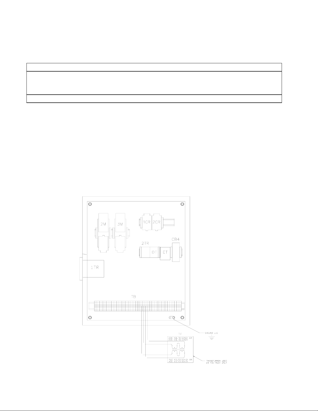
Control Panel (Door Opened), FIGURE 6-1..................................................................................................................6-2
Description of Control Panel Parts (Inside), TABLE 6-1..............................................................................................6-2
Control Panel (Door Closed), FIGURE 6-2...................................................................................................................6-3
Description of Control Panel Parts (Outer Door), TABLE 6-2......................................................................................6-3
Electrical Schematic All Voltages 50-60 Hz. Across Line Start, FIGURE 6-3 .............................................................6-4
7. MAINTENANCE
Preventive Maintenance.................................................................................................................................................7-1
Preventative Maintenance Form....................................................................................................................................7-2
Ice-Making Section........................................................................................................................................................7-3
Cleaning Procedure........................................................................................................................................................7-3
Water Distributors .........................................................................................................................................................7-3
Water Distributors, TABLE 7-1 ....................................................................................................................................7-4
Average Hole Size in Tube-Ice
Water Tank....................................................................................................................................................................7-4
Water Cooled Condenser Cleaning (optional)...............................................................................................................7-5
TABLE OF CONTENTS
Page No.
®
, TABLE 7-2..............................................................................................................7-4
9/30/10
Page 7

TABLE OF CONTENTS
Cooling Tower / Evap. Condenser (optional) ................................................................................................................7-5
Compressor (optional)...................................................................................................................................................7-6
Compressor Maintenance, TABLE 7-4..........................................................................................................................7-7
Oil Trap .................................................................................................................................................................... 7-7
Cutter Gear Reducer......................................................................................................................................................7-7
8. TROUBLESHOOTING
List Of Symptoms..........................................................................................................................................................8-1
Machine Stopped...........................................................................................................................................................8-2, 8-3
Freeze-Up Due To Extended Freezing Period...............................................................................................................8-4
Freeze-Up Due To Ice Failing To Discharge.................................................................................................................8-5
Low Ice Capacity...........................................................................................................................................................8-6, 8-7
Poor Ice Quality.............................................................................................................................................................8-7
High Discharge Pressure................................................................................................................................................8-8
Low Discharge Pressure................................................................................................................................................8-9
High Suction Pressure....................................................................................................................................................8-9
Compressor Running Unloaded During Freeze.............................................................................................................8-9
Compressor Oil Pressure Low.......................................................................................................................................8-10
Compressor Loosing Oil Excessively............................................................................................................................8-10
Machine Short Cycles....................................................................................................................................................8-11
High Compressor Discharge Temperature .....................................................................................................................8-11
Suction Line Frosting To Compressor ........................................................................................... ................................8-11
9. SERVICE OPERATIONS
Automatic Blowdown (Harvest Cycle).......................................................................................................................... 9-1
Cleaning the Ice Making Section...................................................................................................................................9-1
Float Valve (Make-Up Water)....................................................................................................................................... 9-1
Hand Expansion Valve..................................................................................................................................................9-1
Freeze Timer..................................................................................................................................................................9-1
Minature Rocker Switch Settings for Freeze Timer TABLE 9-2...................................................................................9-2
Entering and Displaying Setpoints.................................................................................................................................9-2
Freeze Timer, FIGURE 9-1...........................................................................................................................................9-3
Control Circuit Protection..............................................................................................................................................9-3
Thawing Timer..............................................................................................................................................................9-3
Thawing Timer, FIGURE 9-2........................................................................................................................................9-4
Suggested Condenser Cleaning......................................................................................................................................9-4
Cutter Gear Reducer......................................................................................................................................................9-5
Drive Gear Replacement................................................................................................................................................9-5
Gear Reducer Replacement............................................................................................................................................9-6
Water Tank Removal.....................................................................................................................................................9-7
Cutter Assembly Removal and Installation....................................................................................................................9-8
Bearing Bracket and Cutter Disc Removal....................................................................................................................9-8
Cutter Shaft and Bearing Removal................................................................................................................................9-9
Cutter Shaft and Bearing Installation.............................................................................................................................9-9
P42AL Service Manual
Page No.
iv
Page 8

P42AL Service Manual
v
Cutter Height Adjustment..............................................................................................................................................9-10
Water Tank Installation.................................................................................................................................................9-11
Pumpdown .....................................................................................................................................................................9-11
Removal of Ammonia Refrigerant from the Machine ...................................................................................................9-12
Refrigerant Leaks...........................................................................................................................................................9-12
Non-Condensable Gases................................................................................................................................................9-13
Purging Non-Condensables ...........................................................................................................................................9-13
Draining the Oil Trap.....................................................................................................................................................9-14
Removing Excess Water from Ammonia ......................................................................................................................9-14
Circulating Water Pump Motor .....................................................................................................................................9-15
The Thaw Gas Solenoid Valve......................................................................................................................................9-16
Thaw Gas Solenoid Valve, FIGURE 9-3.......................................................................................................................9-16
The Liquid Feed Solenoid Valve...................................................................................................................................9-17
The Liquid Feed Solenoid Valve, FIGURE 9-4.............................................................................................................9-17
The Thaw Chamber Check Valve..................................................................................................................................9-18
The Thaw Chamber Check Valve, FIGURE 9-9 ...........................................................................................................9-18
Water Flush Solenoid Valve ..........................................................................................................................................9-18
Compressor Cooling Solenoid Valve ( dedicated high side only)..................................................................................9-18
Compressor Oil Changing .............................................................................................................................................9-19
Compressor Inspection ..................................................................................................................................................9-19
Belt Tension...................................................................................................................................................................9-20
Compressor Servicing....................................................................................................................................................9-21
10. OPTIONS AND ACCESSORIES
Length of Ice .................................................................................................................................................................10-2
PLC (Programmable Logic Controller) ........................................................................................................................10-3
11. TABLES AND CHARTS
P42AL Specifications,TABLE 11-1..............................................................................................................................11-2
11-6 Temperature - Pressure Chart for Common Refrigerants, TABLE 11-2............................................................11-7
Conversion Factors: English to Metric, TABLE 11-3 ...................................................................................................11-8
Constants, TABLE 11-4 ................................................................................................................................................11-8
TABLE OF CONTENTS
Page No.
9/30/10
Page 9

TABLE OF CONTENTS
P42AL Service Manual
vi
Page 10

P42AL Service Manual
INTRODUCTION
1-1
1. Introduction
Henry Vogt Machine Co.
A Brief History Of Our Company. Henry Vogt Machine Co. was founded as a small machine
shop in Louisville, Kentucky in 1880. Today, it is one of the world’s leading producers of icemaking equipment.
9/30/10
In 1938, Vogt built the first Tube-Ice
first “sized-ice” machine quickly replaced the old can-ice plants, which required hard labor and large
amounts of floor space for freezing, cutting, and crushing ice by hand.
Vogt Energy-Saving Tube-Ice Machines Are Cost Effective. Today, Vogt Tube-Ice
enjoy a well-earned reputation as the most energy efficient, dependable ice-making equipment in the
world.
Using as little as one-half to one-third the energy required by competitors’ ice makers, Tube-Ice
machines produce the same amount of ice--in restaurants, sports arenas, packing plants, and
wholesale operations around the globe--at great savings.
In addition, Tube-Ice
®
machines are renowned for their long life, giving many customers more than
35 years of dependable service. Ask someone who owns one.
Preview. All the skill in engineering and fabrication that we’ve learned in over a century of
experience is reflected in every Tube-Ice
1938, the process of making Tube-Ice
means of production. The machine’s economic and reliable operation has been proven over and over
again, in a network of varied types of installations throughout the world.
This manual is designed to assist you in the installation, start-up, and maintenance of your unit.
Your Tube-Ice
®
machine will give you a lifetime of service provided you install, maintain, and
service it properly. It is evidence of our desire to deliver to you “the finest ice-making unit ever
made.”
Please read your manual carefully before attempting installation, operation, or servicing of this
professionally-designed piece of equipment. Also, make sure the Warranty Registration/Start-up
Report is completed and returned.
If you have additional questions, please call your distributor. Also, feel free to phone the factory
direct at (502) 635-3000.
®
machine and revolutionized the ice-making industry. Our
®
machines
®
machine. Since Vogt introduced Tube-Ice® machines in
®
ice has been widely recognized as the most economical
®
Page 11

1-2
INTRODUCTION
Important Safety Notice. This information is intended for use by individuals possessing adequate
backgrounds in electrical, refrigeration and mechanical experience. Any attempt to repair major
equipment may result in personal injury and/or property damage. The manufacturer or seller cannot
be responsible for the interpretation of this information, nor can it assume any liability in connection
with its use. It is important that personnel understand the properties of this refrigerant and that they
be thoroughly trained in safe practices for its use and handling. Refer to the enclosed “Anhydrous
Ammonia Safety” in Appendix A.
Safety Symbols & What They Mean. Prior to installation or operation of the Tube-Ice
please read this manual. Are you familiar with the installation, start-up, and operation of a Tube-
®
Ice
machine? Before you operate, adjust or service this machine, you should read this manual,
understand the operation of this machine, and be aware of possible dangers.
These safety symbols will alert you
when special care is needed.
P42AL Service Manual
®
machine,
Please heed them.
! DANGER !
Indicates an immediate hazard and that special precautions
are necessary to avoid severe personal injury or death.
! DANGER !
! WARNING !
Indicates a strong possibility of a hazard and that an
unsafe practice could result in severe personal injury.
! WARNING !
! CAUTION !
Means hazards or unsafe practices could result
in personal injury or product or property damage.
! CAUTION !
9/30/10
Page 12

P42AL Service Manual
INTRODUCTION
1-3
Special Precautions To Be Observed When Charging Refrigeration Systems. Only technically-
qualified persons, experienced and knowledgeable in the handling of anhydrous ammonia refrigerant
and operation of refrigeration systems, should perform the operations described in this manual. All
local, federal, and EPA regulations must be strictly adhered to when handling ammonia (R-717)
refrigerant. See “Material Safety Data Sheet”, MSDS Code No. 5B81-83.
If a refrigeration system is being charged from refrigerant cylinders, disconnect each cylinder when
empty or when the system is fully charged. A gage should be installed in the charging line to
indicate refrigerant cylinder pressure. The cylinder may be considered empty of liquid R-717
refrigerant when the gauge pressure is 25 pounds or less, and there is no frost on the cylinder. Close
the refrigerant charging valve and cylinder valve before disconnecting the cylinder. Loosen the
union in the refrigerant charging line--carefully to avoid unnecessary, excessive or illegal release of
refrigerant into the atmosphere.
! CAUTION !
Immediately close system charging valve at commencement of defrost or thawing cycle if
refrigerant cylinder is connected. Never leave a refrigerant cylinder connected to system
except during charging operation. Failure to observe either of these precautions can result in
transferring refrigerant from the system to the refrigerant cylinder, over-filling it, and
possibly causing the cylinder to rupture because of pressure from expansion of the liquid
refrigerant brought on by an increase in temperature.
! CAUTION !
Always store cylinders containing refrigerant in a cool place. They should never be exposed to
temperatures higher than 120°F and should be stored in a manner to prevent abnormal mechanical
shocks.
Also, transferring refrigerant from a refrigeration system into a cylinder can be very dangerous and
is not recommended.
! CAUTION !
It is not recommended that refrigerant be transferred from a refrigeration system directly into
a cylinder. If such a transfer is made, the refrigerant cylinder must be an approved, CLEAN
cylinder--free of any contaminants or foreign materials--and must be weighed continuously to
assure contents do not exceed net weight specified by cylinder manufacturer or any applicable
code requirements.
! CAUTION !
9/30/10
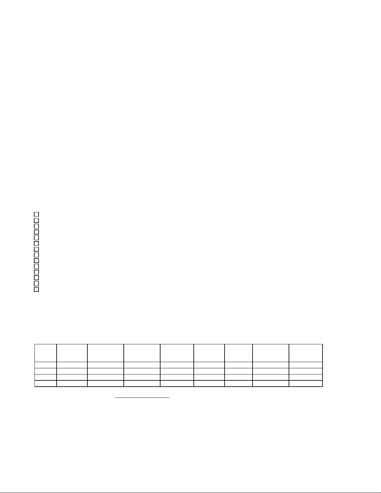
Page 13
1-4
INTRODUCTION
P42AL Service Manual
9/30/10
FIGURE 1-1
P42AL Front Side (Control Panel)
Page 14
P42AL Service Manual
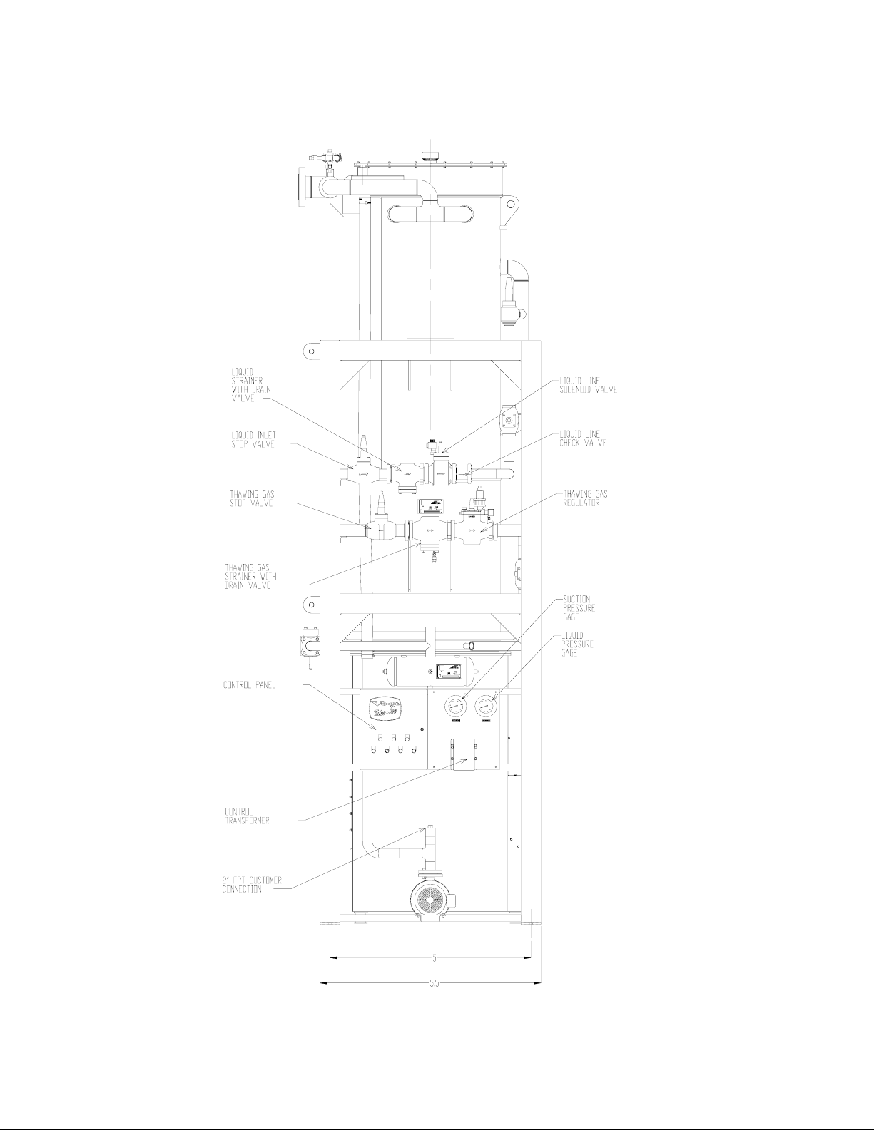
INTRODUCTION
1-5
9/30/10
FIGURE 1-2
P42AL Right Side
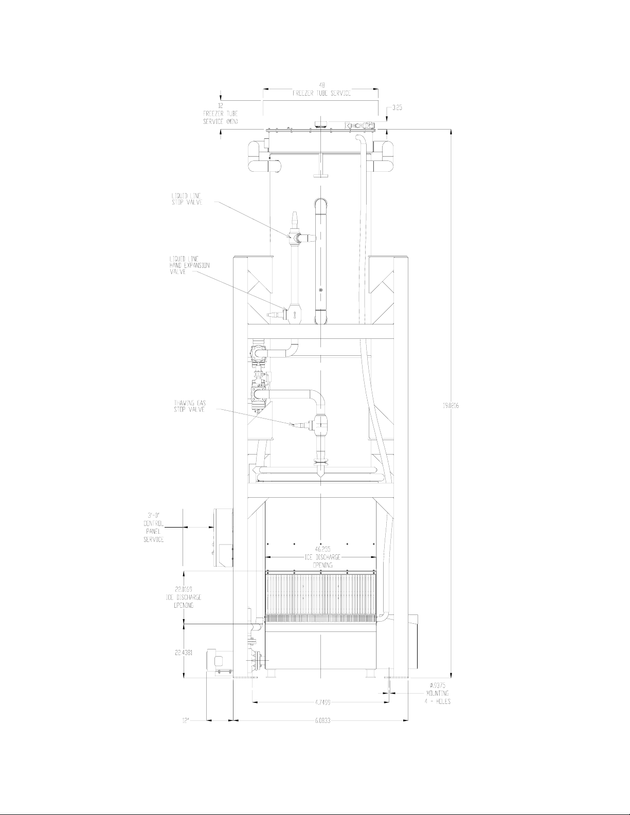
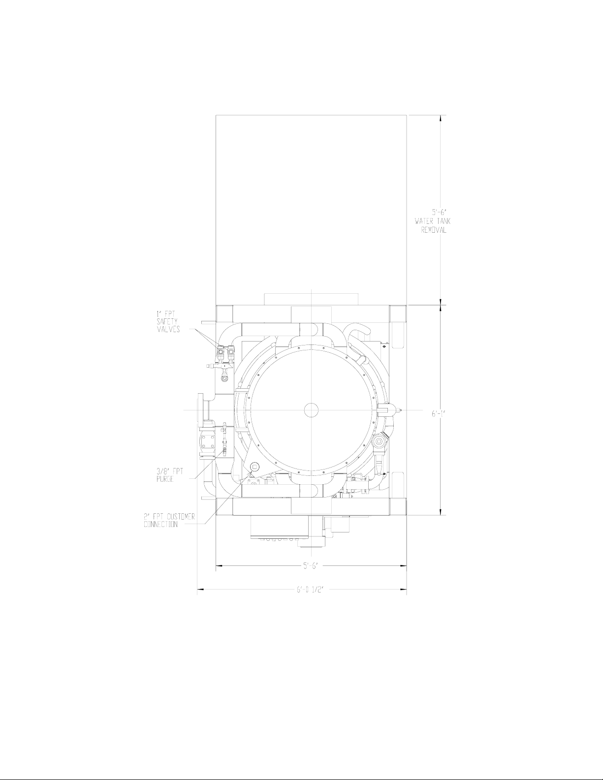
Page 15
1-6
INTRODUCTION
P42AL Service Manual
9/30/10
FIGURE 1-3
P42AL Left Side
Page 16
P42AL Service Manual
INTRODUCTION
1-7
9/30/10
FIGURE 1-4
P42AL Top
Page 17

1-8
INTRODUCTION
P42AL Service Manual
9/30/10
Page 18

P42AL Service Manual
Inspection. As soon as you receive your machine, inspect it for any damage. If damage is
suspected, note it on the shipper’s papers (i.e., the trucker’s Bill of Lading). Immediately ma ke a
separate written request for inspection by the freight line’s agent. Any repair work or alteration to
the machine without the permission of the Henry Vogt Machine Co. can void the machine’s
warranty. You should also notify your Vogt distributor or the factory.
Description Of Machine. A Vogt low side Tube-Ice
requiring refrigerant suction connection, refrigerant liquid connection, thaw gas connection, makeup water supply, electrical connection, and the proper refrigerant charge.
The machine has been partially factory tested prior to shipment and will require adjustment to meet
the high side (condenser unit) operating conditions. See Start-up and Operation for the correct
setting of the controls.
After factory pressure testing of the machine, the machine is evacuated and charged with nitrogen
gas pressure for shipment. This prevents air or moisture from entering the system during transit.
There should be a positive pressure (20-25 psig) indicated on the control panel gages when the
machine is received. The machine has been cleaned with ice machine cleaner and flushed so that the
machine is ready for ice production.
Safety Tags and Labels. Be sure to read and adhere to all special tags and labels attached to valves
or applied to various areas of the machine. They provide important information necessary for safe
and efficient operation of your equipment.
The machine is available in three different tube sizes for producing ice 7/8” OD x 1” long, 1 1/8”
OD x 1” long, or 1 3/8” OD x 1” long. The ice is cut to length by a rotating breaker type cutter. Ice
can be produced up to 1 1/2” long by modifying the spacers under the adapter plates (see Chapter 10,
“Ice Length” for modifying instructions). Crushed ice is also available by modifying the cutter and
making minor adjustments to the machine (see Chapter 10, “Crushed Ice”).
RECEIPT OF YOUR TUBE-ICE MACHINE
2. Receipt Of Your Tube-Ice Machine
! CAUTION !
Only service personnel experienced in ammonia refrigeration and
qualified to work on high amperage electrical equipment should
be allowed to install or service this Tube-Ice® machine.
Eye protection should be worn by all personnel
working on or around the Tube-Ice® machine.
It is very important that you are familiar with and adhere to
all local, state, and federal, etc. ordinances and laws regarding
the handling, storing, and use of anhydrous ammonia.
An approved ammonia mask should be readily available
for use in an emergency and all personnel should be aware
of its location and proper use.
! CAUTION !
®
machine is a remote ice producing plant
2-1
9/30/10
Page 19
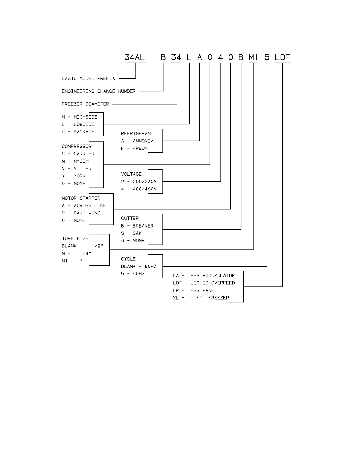
2-2
RECEIPT OF YOUR TUBE-ICE MACHINE
P42AL Service Manual
9/30/10
FIGURE 2-1
Model Designation for P-Series Ice Machines
Rated Capacity. The Tube-Ice
®
machine is rated to produce a given amount of ice when operating
under the proper conditions as specified in this manual (see Section 11 for the operating
specifications). You should be prepared to handle the ice produced as it is discharged from the
machine and move it to your storage or bagging area promptly.
Storage (prior to installation or start-up). The machine must not be stored or installed in an area
that is subject to reach temperatures at or above 110°F (43.3°C).
Page 20

P42AL Service Manual
Your machine will be shipped to you as one package. You will need to arrange for the handling of
the package as soon as it arrives, see the machine specifications Section 11 for shipping and
operating weight. Before you remove the unit from the truck, be certain that any sign of damage,
however slight, is noted on the carrier’s papers.
Note: See “Lifting Procedure” drawing furnished with this manual, Fig 3-5 and 3-6.
Machine Room. The machine must be located inside a suitable building and must not be subjected
to ambient temperatures below 50°F (10°C) or above 110°F (43.3°C). Heat radiation from other
sources (sunlight, furnaces, condenser, etc.) and unusual air current may affect the operation of the
machine and should be avoided. The electrical components of the Tube-Ice
NEMA 1. Therefore, the machine should not be located in a hazardous area or sprayed with
water. The machine should be installed in an area where water will not stand, but will readily drain
away from the machine.
Space Requirements. Refer to the space diagrams, Figures 1-2 and 1-4, for recommended
minimum clearance around the machine for ease of servicing and observation. Pay particular
attention to the additional space required. If it ever becomes necessary to mechanically clean the
freezer tubes, extra space will be required.
Foundation. Refer to the space diagrams, Figures 1-2,1-3 and 1-4, for recommended minimum
foundation requirements. The figures show anchor bolt details and machine anchor hole details.
Contact your local distributor for seismic anchoring requirements in your area.
Lifting Procedures. Your Tube-Ice
unloading and moving the machine to its operation location. Refer to the enclosed drawings for
instructions and illustrations of their use.
P42AL - Machine weight 13,200 lbs.
These figures are intended as a guide to unloading and lifting the P42AL Tube-Ice
Vogt Tube-Ice LLC is not responsible for product damage or personnel injury or loss of life
during the loading or lifting procedure.
INSTALLING YOUR TUBE-ICE MACHINE
3. Installing Your Tube-Ice Machine
®
machine are rated
! WARNING !
Lifting or moving heavy equipment should only be attempted by
competent rigging and hoisting contractors. Never allow personnel
near or under heavy equipment when it is being moved or lifted.
Failure to comply could result in personal injury or loss of life.
! WARNING !
®
machine is provided with lifting lugs for the purpose of
®
machine. The
3-1
9/30/10
Page 21
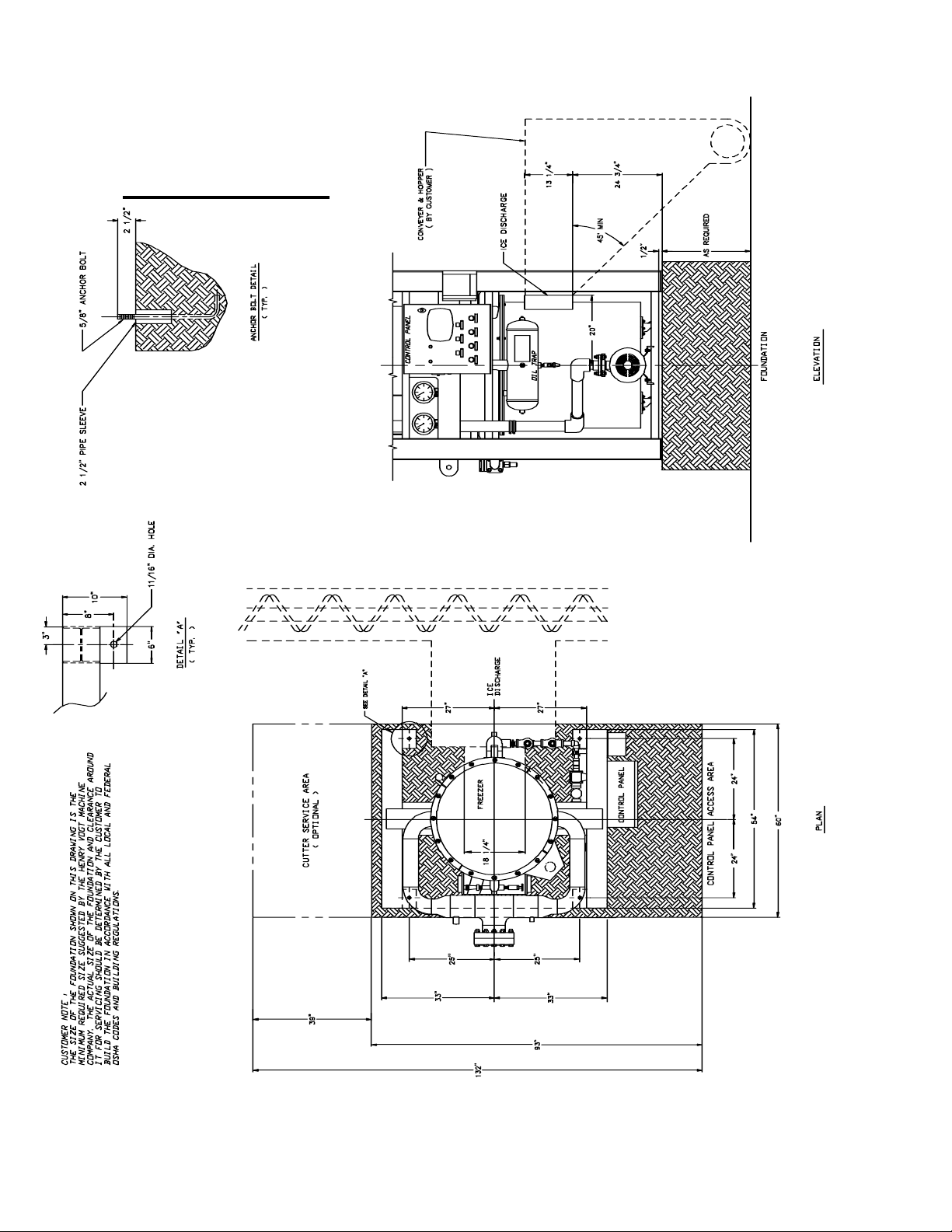
3-2
INSTALLING YOUR TUBE-ICE MACHINE
Reference Only
P42AL Service Manual
9/30/10
FIGURE 3-1
P42AL Foundation Layout
Page 22
P42AL Service Manual
INSTALLING YOUR TUBE-ICE MACHINE
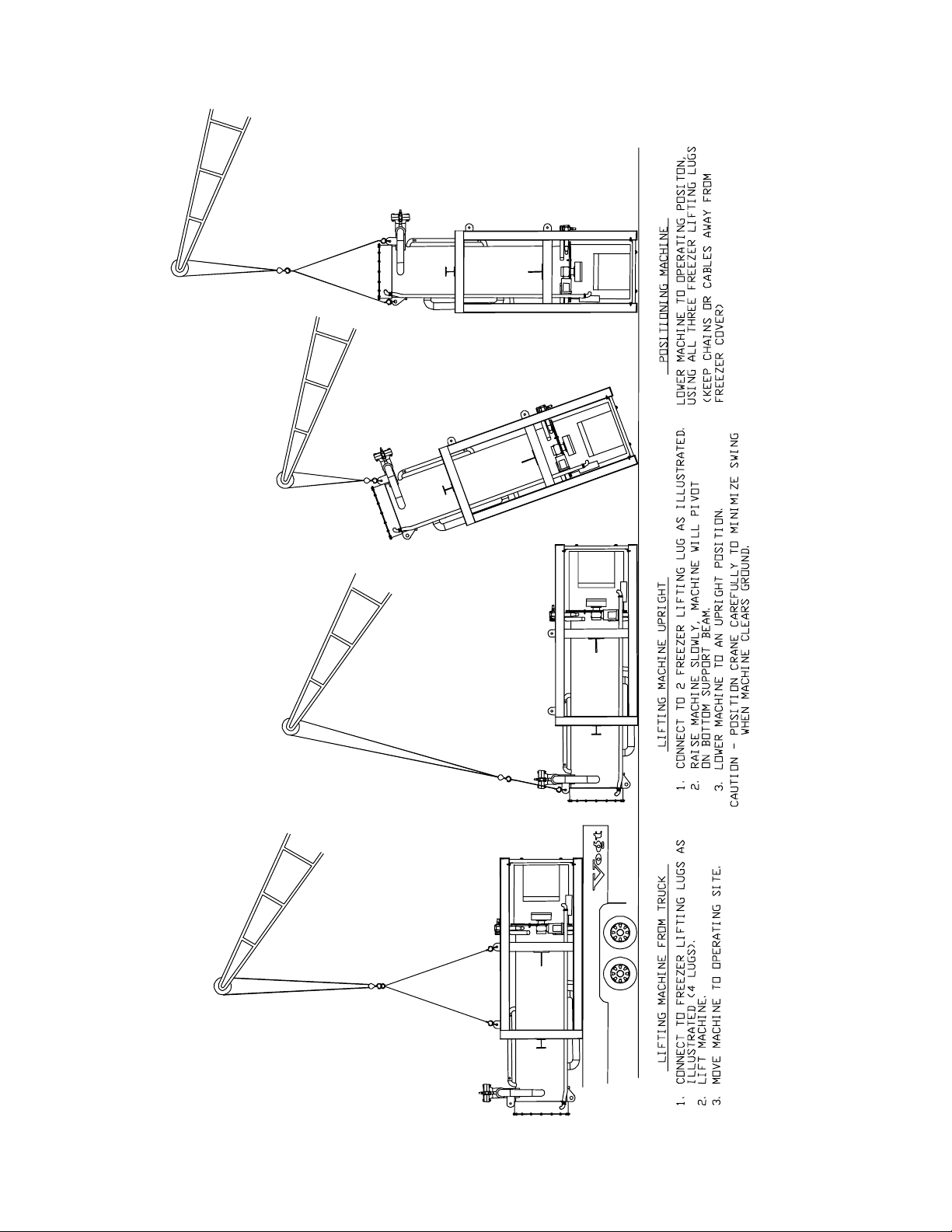
3-3
9/30/10
FIGURE 3-2
Lifting Procedure for P42AL
Page 23
3-4
INSTALLING YOUR TUBE-ICE MACHINE
P42AL Service Manual
9/30/10
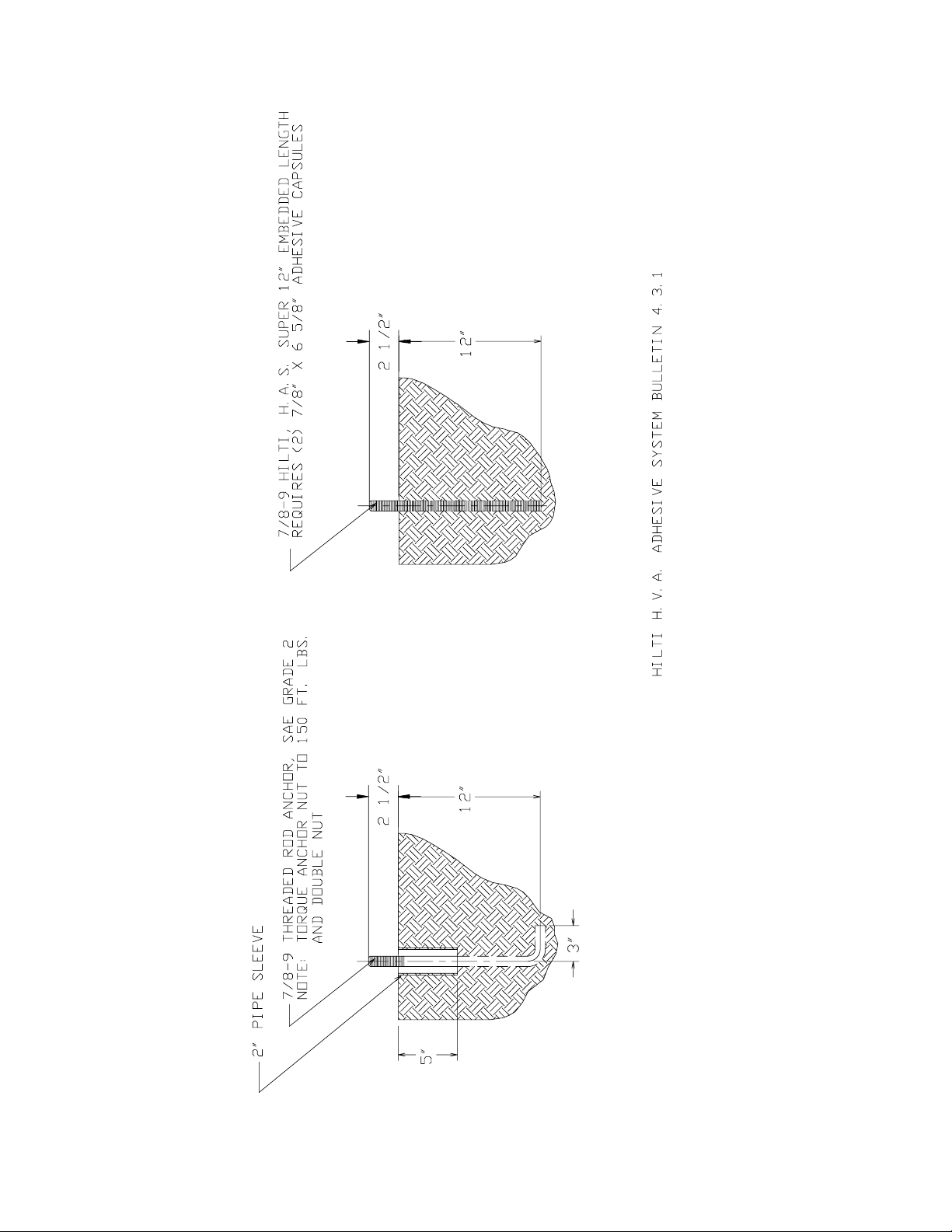
FIGURE 3-3
Seismic Anchoring Detail for P42AL Tube-Ice Machine
Page 24

P42AL Service Manual
Piping and Drain Connections. See Figure 1-1 to 1-8 and 3-11 to 3-17 for connection locations.
When connecting refrigeration piping, you must follow and adhere to all ANSI/ASHRAE 15 “
Safety Code for Mechanical Refrigeration” and ANSI Standard B-31.5 “ Refrigeration Piping
Code”. Also, all piping must conform to all state and local codes. Make sure all piping is kept
clean, dry and contaminate free. All piping should be supported properly.
Model
P42AL 11/2” FPT 3/4” FPT
* Mating 4 bolt flange supplied with machine.
** Liquid connection is all purpose coupling.
Make-Up Water In. The water required for ice making must be potable water, safe for human
consumption, and should be of the highest quality available. The best way to determine water
quality is to have a complete water quality analysis by a qualified laboratory.
It is advisable to install a particle filter in the make-up and flushing water lines to trap dirt, sand,
rust, or other solid particles prior to entering the water tank and contaminating the ice. Be sure to
size the filter large enough to meet the water demands of 15 GPM (peak flow), allowing for a
restriction through the filter as it traps these particles. The inlet water pressure should be a minimum
of 40 psi. Refer to TABLE 3-1 for line size and Section 11 for average flow rate at various water
temperatures.
Flushing Water In. Flushing water (blowdown) is necessary to melt ice fines and flush dissolved
solids from the water tank during the thawing (harvest) cycle. This function is important and helps
to maintain good ice quality. If water quality is superior, installing a smaller orifice in the flushing
outlet elbow can reduce this blowdown. Make sure there is enough flushing water to prevent the
accumulation of excessive ice fines in the tank.
If make-up and flushing water are from the same source, a common line to the machine can connect
them.
9/30/10
Make-up
Water In
INSTALLING YOUR TUBE-ICE MACHINE
! CAUTION !
Exterior shut-off valves must be provided in the water
inlet lines. The minimum inlet water pressure for
satisfactory operation of the machine is 40 psig.
The maximum allowable pressure is 100 psig.
! CAUTION !
Flushing
Water In
Water
Tank
Drain
Water
Tank
Overflo
w
Low Side
Suction
Connectio
n*
2” FPT 3” FPT 6” SW
104gal/3 min.
Flange
TABLE 3-1
Water Supply, Drain and Refrigeration Connections
(See FIGURE 1-1 through 1-4 for locations)
Low Side
Liquid
Connection*
*
2 1/2” FPT
or SW
Low Side
Thaw Gas
Connectio
n
3” SW
Flange
3-5
Page 25

3-6
INSTALLING YOUR TUBE-ICE MACHINE
P42AL Service Manual
Water Tank Drain. This valve and connection is for the purpose of flushing and draining the water
tank of impurities, foreign material and cleaning chemicals used during servicing. It should be piped
to an open drain or sump for visible discharge. It can be tied in with the overflow line but no others.
Water Tank Overflow. A 3” FPT connection on the side of the water tank is provided to carry
away overflow water during the thawing (harvest cycle). This water contains ice fines accumulated
during harvesting and dissolved solids accumulated during the freezing cycle. Do not reduce the
size of this line. Three inches is needed to provide sufficient area for ice fines to be flushed out,
especially if the incoming flushing water is 55°F (13°C) or below. This overflow line should not tie
in with any other drain line except the water tank drain.
Unless water quality is superior, do not discharge the overflow water to the cooling tower system.
This water contains additional dissolved solids left from the ice making process and can lead to
excessive condenser fouling or cooling tower chemical usage. It is recommended that a heat
exchanger be used in place of direct contact with condenser water.
Receiver. The receiver used to supply hot thaw gas must be sized adequately to provide suffecient
thaw gas. Table 3-2 shows the volume required to hold the refrigeration charge of the freezer and
the hot gas required for the thaw cycle. It is recommended that a heating coil be installed in the
receiver to assure that the liquid ammonia is at saturated temperature at the start of each thaw period.
Note: Additional storage volume may be required for the interconnecting piping. Add volume of
interconnecting piping to the values shown in Table 3-2
MODEL
P42AL
RECEIVER VOLUME (Cubic Feet)
With Heating Coil With out Heating Coil
70 100
TABLE 3-2
Receiver Volume Requirements
Thaw Gas Pressure Regulator. The thaw gas pressure regulator is a 2” solenoid operated pressure
combination regulator and shut-off valve (see figures 1-2 and 1-5 for locations). Do not reduce the
size of this line. This valve is deigned to carry the proper amount of thaw gas to the evaporator
during the harvest cycle. See section 5-7 for operating instructions.
Suction Pressure Regulator. When a P42AL is attached to a central system a n evaporator
pressure regulator will be required (see Figures 3-15 through 3-16 for location). This regulator
(usually furnished by the purchaser) must be a combination back-pressure regulating and open type
valve. The usual minimum pressure drop across this type valve is 2 psig, therefore the valve must be
set to maintain a freezer pressure at least 2 psi above the maximum general suction pressure. A
throttling by-pass line with a solenoid shut-off and hand valve for regulating flow should accompany
this valve.
Compressor Unloading. When multiple P42AL are attached to a dedicated compressor system
unloading of the compressor may be required. A minimum compressor unloading during the harvest
cycle is 50%. If the compressor can’t be unloaded then a hot gas bypass to the suction line must be
installed.
9/30/10
Page 26
P42AL Service Manual
Wiring and Electrical Connections.
A fused disconnect must be provided near the Tube-Ice
transformer (if required) are attached to the structurals on the front of the Tube-Ice
FIGURE 3-11). Incoming 3-phase power will be connected at the cutter motor circuit breaker
(CB3). Terminals L1, L2, L3 for operation of the Tube-Ice® machine and its controls. Rotation
checking of the, cutter motor, and water pump and auxiliary equipment is required (see rotation
check). Also, if one leg of the 3-phase power is higher or lower (“wild”), then it should be
connected to terminal L3. Connect the ground wire to the “ground” terminal provided.
Make sure wires #22 and #27 are connected to the elapse time (ET) indicator in the control panel.
INSTALLING YOUR TUBE-ICE MACHINE
! WARNING !
Only service personnel experienced in refrigeration and qualified
to work with high voltage electrical equipment should be allowed
to install or work with the Tube-Ice® machine.
! WARNING !
®
machine. The control panel and
®
machine (see
3-7
9/30/10
FIGURE 3-4
Power Supply Connections
Page 27

3-8
INSTALLING YOUR TUBE-ICE MACHINE
P42AL Service Manual
Voltage Unbalance Voltage unbalance can cause motors to overheat and fail. Voltage imbalance
between any two legs should be no greater than 2%.
Example: Supply voltage = 230-3-60
Voltage Readings: AB = 220 Volts
BC = 225 Volts Average = (220 + 225 + 227)/3 = 224 Volts
AC = 227 Volts
(AB) 224-220 = 4 Volts (Highest Deviation)
(BC) 225-224 = 1 Volts
(AC) 227-224 = 3 Volts
% Voltage Unbalance = 100 x (4/224) = 1.78% “Acceptable”
Important: If the supply voltage phase unbalance is more the 2%, contact your local electric
utility company.
Current Unbalance Voltage unbalance will cause a current unbalance, but a current unbalance
does not necessarily mean that a voltage unbalance exists. A loose terminal connection or a buildup
of dirt or carbon on one set of contacts would cause a higher resistance on that leg than on the other
two legs. Current follows the path of least resistance, therefore if terminal connection L1 is loose or
dirty, L2 and/or L3 will have higher current.
Higher current causes more heat to be generated in the motor windings. The maximum acceptable
current unbalance is 10%.
Example:
Current Readings: L1 = 96 Amps
L2 = 91 Amps Average = (96 + 91 + 98)/3 = 95Amps
L3 = 98 Amps
(L1) 96-95 = 1 Amps
(L2) 95-91 = 4 Amps (Highest Deviation)
(L3) 98-95 = 3 Amps
% Current Unbalance = 100 x (4/95) = 4.2% “Acceptable”
Rotation Check. The compressor, cutter, and pump motor rotation are factory synchronized, but
must be checked at installation. For cylinder ice production, the cutter disc as viewed at the ice
discharge opening should turn from left to right.
Check rotation by the following procedure:
1. Turn the power to the machine on and check voltages.
2. Make sure the water tank is full of clean water.
3. Turn the Hand-Auto switch (ISS) to HAND position. The water pump will start and the freezing
(1LT) and the liquid feed (2LT) pilot lights will illuminate. Check pump rotation.
9/30/10
Page 28

P42AL Service Manual
4. Push the MANUAL HARVEST button. The water pump will stop, the “Freezing and Liquid
Feed” lights will go out, and after 20-30 seconds, the cutter motor will start. The thawing gas
solenoid valve will open and the “Thawing” pilot light (3LT) will illuminate.
5. Check the cutter disc rotation. It should be turning from left to right (CCW looking from the
top).
6. Turn the HAND-AUTO switch to AUTO to stop the cutter.
To change rotation, follow this procedure:
1. Disconnect power to the machine and lock it out to make sure it can’t be turned back on.
2. Check for power at L1, L2, L3 with a volt meter to make sure it is off.
3. At the cutter motor circuit breaker (CB3) or at the power disconnect, reverse wires L1 and L2.
4. Make sure these terminals are tight and restore power to the machine.
5. Perform rotation check again to confirm that it is correct.
Auxiliary Controls or Equipment. When connecting other equipment such as high/low pressure
swith, conveyor motors, bin level control, etc., refer to the control panel wiring drawing for the
proper connecting terminals and instructions. See Figure 6-3.
INSTALLING YOUR TUBE-ICE MACHINE
! CAUTION !
Do not attempt to start the machine until first making sure all
conditions listed in the Installation Review Checklist and all
necessary valves have been opened for operation.
! CAUTION !
3-9
9/30/10
Page 29
3-10
INSTALLING YOUR TUBE-ICE MACHINE
P42AL Service Manual
9/30/10
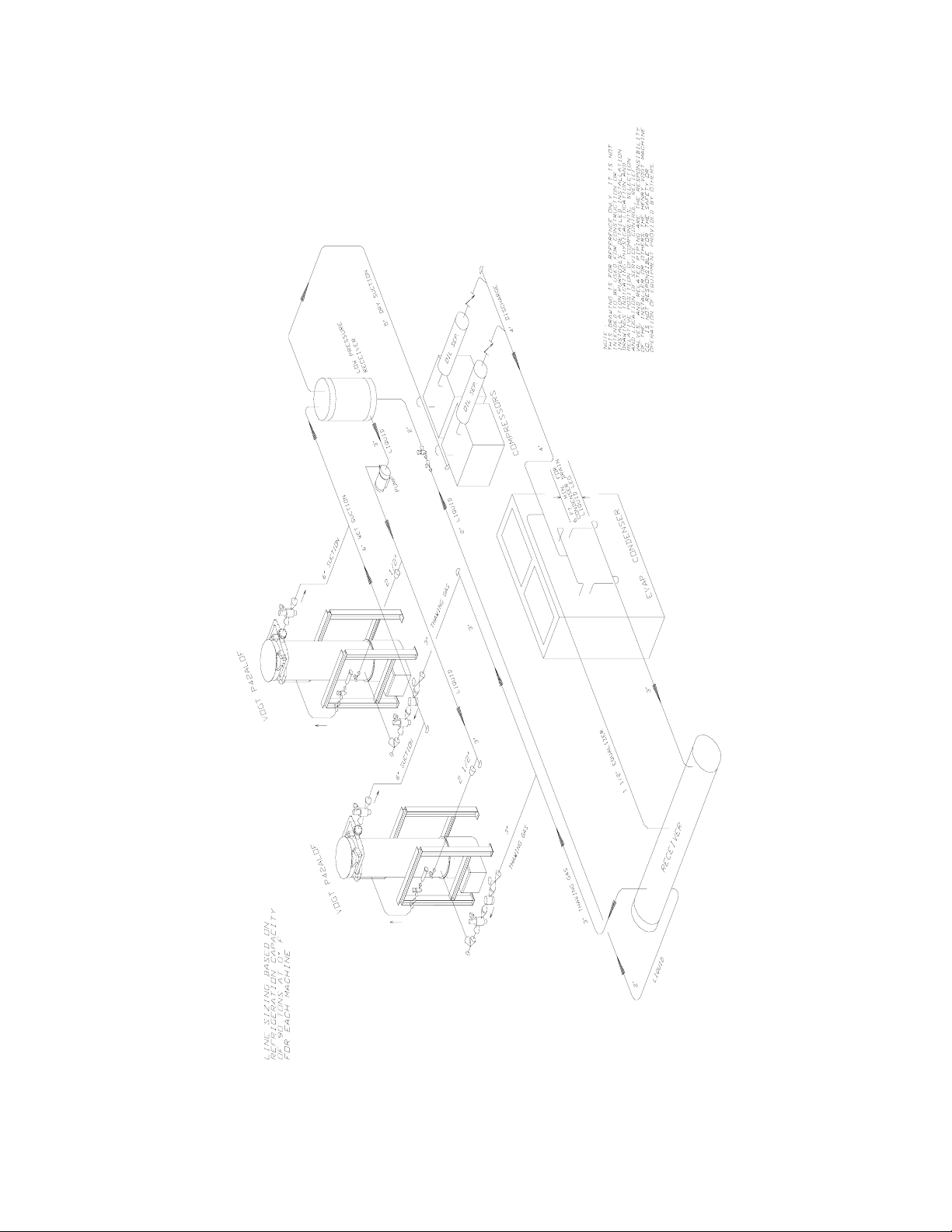
FIGURE 3-5
Interconnecting Piping for 2-Vogt P42AL and Central High Side
Page 30

P42AL Service Manual
Installation Review: A Checklist. Make a visual check to be sure these steps have been taken
BEFORE continuing.
CHECK: _____ PRIOR TO OPENING VALVES, check all joints for leaks which may have
developed during shipment. (NOTE: the machine was shipped with a positive pressure of 20-25
PSIG, which should be indicated on the suction and discharge gages.)
CHECK: _____ The system is properly evacuated to 500 microns.
CHECK: _____ All refrigerant piping, water supply and drain connections for conformity to
requirements stipulated in this manual and properly connected to inlets and outlets.
CHECK: _____ Electrical supply for proper size of fuses and for compliance to local and national
codes. See the machine nameplate for minimum circuit ampacity and maximum fuse size.
CHECK: _____ All field installed equipment (augers, conveyors, cooling towers, bin level controls,
etc.) for proper installation.
CHECK: _____ The applicable portion of the warranty registration/start-up report for proper
completion.
CHECK: _____ Cutter gear reducer oil level oil should run out of side pipe plug when removed.
CHECK: _____ The water distributors at top of freezer to make sure they are all in position (one
seated firmly in each tube with a vent tube in each distributor).
INSTALLING YOUR TUBE-ICE MACHINE
! IMPORTANT !
Be sure to follow the wiring schematic when incorporating overloads of
conveyor (5 MOL). Also remove jumpers as instructed.
This is necessary to provide proper
protection for the Tube-Ice® machine and its component parts.
! IMPORTANT !
! CAUTION !
The compressor crankcase heater should be energized for a minimum of
four hours and the oil temperature should be 100-110°F
before attempting to start the compressor.
! CAUTION !
3-11
9/30/10
Page 31

P42AL Service Manual
HOW YOUR TUBE-ICE MACHINE WORKS
4. How Your Tube-Ice Machine Works
4-1
Operating Features. Your Vogt low side Tube-Ice
®
machine is an efficient ice producing plant. If
installed and maintained properly, it will give many years of operation with a minimum amount of
repairs. Refer to piping schematics, FIGURE 4-1 and 4-2 to identify component parts while
following the information and instructions in this manual.
The machine is manually started and stopped by the START and STOP push buttons. The machine
will automatically stop by safeties such as, cutter and pump overloads, as well as other auxiliary
motor overloads. It will also stop automatically by high head pressure, low suction pressure (if field
wired to the high side). The circulating water pump can be operated independently for chemically
cleaning the freezer tubes and water tank by use of the HAND/AUTO selector switch. The machine
can be manually forced into a harvest cycle with the manual harvest push button.
Liquid Overfeed Principle of Operation. The freezer (2) is a shell and tube-type vessel designed
to operate on a liquid overfeed refrigeration system. During the freezing period (cycle), water is
constantly recirculated through the vertical tubes of the freezer by a centrifugal pump (6). Make-up
water is maintained by a float valve (12) in the water tank (7). The refrigerant is pumped or
recirculated through the liquid feed “A” solenoid valve (20) and maintains the desired refrigerant
flow in the freezer (2) (evaporator). The refrigerant flow rate (overfeed) is 3:1.
The evaporated refrigerant gas and liquid mixture from the top of the freezer (2) passes through the
suction connection to the wet suction header and back to the low-pressure receiver (overfeed tank).
After separation the cool gas from the low-pressure receiver, passing through the dry suction header,
is compressed to a high temperature, high pressure gas which discharges through the oil separator
(then through the heat coil of the receiver, when installed) and to the condenser. In the condenser,
heat is removed and the gas is condensed to a high temperature, high-pressure liquid. The highpressure liquid passes through the liquid line through a strainer, liquid solenoid valve, check valve,
and hand expansion valve to the low-pressure receiver. At the hand expansion valve, the refrigerant
expands from a saturated high-pressure liquid state to a low pressure, low temperature liquid. This
cold liquid enters the low-pressure receiver where it is pumped to the freezer. Cool gas and liquid
mixture is again pulled out of the freezer through the suction outlet, thereby completing the circuit.
The freezing period is completed by action of the freeze timer (1TR) in the control panel. The water
pump (6) stops and the “A” solenoid valve (20) closes. After a delay of 20-30 seconds, the cutter
motor starts, the thawing gas “D” solenoid valve (18R) opens, and the harvest (thawing) timer (2TR)
is activated. Warm gas from the receiver is discharged through the thawing chamber (16), check
valve (101), and into the freezer. There it warms the refrigerant and the outer surface of the freezer
tubes, allowing the ice to release on the inside of the tubes and drop down onto the rotating cutter for
sizing. After sizing, the ice drops on the tines cutter disc and is discharged through the ice discharge
opening.
See “Freeze Period” and “Harvest Period” for more detailed description of machine.
Freeze Period. The Tube-Ice
®
is frozen inside the stainless steel tubes of the freezer (2) by the
direct application of refrigerant to the outside shell side of the tubes. Ice is produced from constantly
recirculating water down each tube. Overfeed of the liquid refrigerant to the freezer enhances heat
transfer, therefore reducing freeze times. At a set time the freeze timer (1TR) energizes the relay
(1CR), which stops the water pump, closes the “A” liquid feed solenoid valve (20), de-energizes the
9/30/10
Page 32

4-2
HOW YOUR TUBE-ICE MACHINE WORKS
suction regulator (when installed), turns out the two pilot lights, ammonia feed and freezing. Note:
the liquid feed should be delayed for approximately 30 seconds at the beginning of the freeze cycle.
Harvest Period. About 20-30 seconds after the 1CR relay is energized, the thaw gas valve (18)
opens, the “H” water flush solenoid valve (63) opens, the compressor unloads (when required), the
cutter motor starts, the thaw timer (2TR) is energized, the red thawing gas light illuminates, and
auxiliary equipment such as conveyors etc. start. When the refrigerant in the freezer is warmed
sufficiently, approximately 40°F / 5°C, to allow the ice in the tubes to release and fall to the cutter
for sizing. The ice is then discharged into the customers’ ice handling equipment. See “Ice
Handling” for more information on this subject. The thaw timer (2TR) is adjustable and should
be set for the time required for all the ice to clear the freezer plus 30 seconds more.
Make sure all the ice clears the freezer with at least 30 seconds
to spare before the next freezer period begins. This is to prevent
refreezing and to allow the ice moving augers etc. to clear.
1 Control Panel 36 Oil Trap
1PG Suction Pressure Gauge 39 Water Tank Drain Valve
2PG Discharge Pressure Gauge 43 Strainer
2 Freezer 44 Receiver Drain Valve
5M Cutter Motor 46 Filter Drier
5R Gear Reducer 49 Freezer Suction Stop Valve or Regulator
6 Water Pump 51 Freezer Safety Valve
7 Water Tank (includes cutter assembly) 52 3-Way Valve
8 Water Distributing Chamber 61 Freezer Oil/Ammonia Drain Valve
9 Water Tank Overflow (3” FPT) 62 Make-up Water Inlet Valve
12 Make-Up Water Float Valve 63 Water Flush Solenoid Valve
16 Thawing Chamber 69 Low Suction Pressure Stop Valve
17 Hand Expansion Valve 75 Strainer Purge Valve
18 Thawing Gas Regulator/Solenoid Valve “D” 76 Freezer Purge Valve
20 Liquid Feed Solenoid Valve “A1” 82 Thaw Gas Pressure Gage Stop Valve
28 Refrigerant Charging Valve 90 Thawing Gas Stop Valve
29 Liquid Line Stop Valve 101 Check Valve
30 Sight Glass
31 Gage Glass Stop Valve
9/30/10
P42AL Service Manual
! CAUTION !
! CAUTION !
Piping Nomenclature
Page 33

P42AL Service Manual
4-3
HOW YOUR TUBE-ICE MACHINE WORKS
9/30/10
FIGURE 4-1
Piping Schematic for P42AL
Page 34

4-4
HOW YOUR TUBE-ICE MACHINE WORKS
P42AL Service Manual
9/30/10
Page 35

P42AL Service Machine 5-1
START-UP & OPERATION
5.Start-Up & Operation
Refrigeration System Review. The refrigeration system uses recirculated anhydrous ammonia
(R-717) refrigerant. Following the piping schematic (Figure 3-12 to 3-16 and 4-1 or 4-2), you will
see that a recirculated or overfeed refrigeration system is actually two systems. One can be
described as a standard refrigeration system where the low-pressure receiver acts as the evaporator
and the other is a refrigerant pumping system. A liquid overfeed system can only be applied to
two or more evaporators or one evaporator attached with other base loads (i.e. production cooling
loads).
During all cycles the compressor discharge gas goes through the oil separator to remove any oil
present in the discharge gas and return the oil to the compressor crankcase. It is then discharged
into the condenser and condensed into a liquid by the removal of heat by passing water through the
condenser tubes. A reservoir of liquid R-717 (approximate 325 lbs. for P42AL and 944 lbs. for
P34ALOF) is accumulated in the high pressure receiver and is required for thawing purposes (see
Table 3-2). Liquid from the high-pressure receiver flows through the strainer to the solenoid
valve, which opens and closes by action of the float switch on the low-pressure receiver (the float
switch should be positioned to maintain suitable head on the liquid pump and a high level cutout
should be installed). The liquid is then expanded through the hand expansion valve and into the
low-pressure receiver. The cold wet R-717 refrigerant is now pumped to the evaporator and comes
in contact with the outside of the ice making tubes which water is being circulated through. The
heat contained in the water passes through the wall of the tubes, lowering the temperature of the
water causing it to freeze and form a long tube of ice that adheres to the inside of freezer tubes.
Since the purest water freezes first, the circulating water continues to wash the dissolved solids
down into the sump area of the water tank. The flushing valve helps to rid the water tank of
increased dissolved solids by flushing them out the overflow during the harvest (thawing) period.
The wet suction gas leaves the freezer and passes through the low-pressure receiver, where liquid
droplets are removed, allowing dry gas to enter the suction side of the compressor. The suction
gas is then compressed and discharged once again, completing the cycle. As ice continues to form
in the freezer tubes, the suction pressure steadily decreases, when the freeze timer (1TR) times out
the contact closes, initiating the thaw (harvest) cycle. Freezing requires about 12 minutes, but can
vary depending on ice thickness, suction pressure, discharge pressure and distance from the LPR to
the freezer.
Note: Freezing time will vary, depending on make-up water temperature, suction pressure and
thickness of ice produced. The freeze timer (1TR) should be set to provide the correct time to
produce ice at the required thickness under the current operating conditions.
During the harvest period, the “D” thawing gas valve (18) opens and the compressor unloads
(when required), allowing the warm high-pressure gas from the receiver to enter the freezer. As
the tubes warm up to slightly above freezing (approximately 40°F / 5°C), the ice inside the tubes
releases and falls down onto the rotating cutter for sizing and discharging. Harvesting requires
about three minutes, but can vary depending on ice thickness, suction pressure, discharge pressure
(thawing gas temperature) and distance from the receiver to the freezer.
9/30/2010
Page 36

5-2 P42AL Service Manual
START-UP & OPERATION
Note: Only one evaporator should harvest at a time. If multiple machines harvest during the same
period, the high-pressure receiver may not supply enough hot gas to harvest either machine,
causing a freeze-up situation. The pressure in the high-pressure receiver should be allowed to
recover before another machine is allowed to harvest.
! IMPORTANT !
It is a good idea and will be profitable for you to observe and
become familiar with the proper operating characteristics of your
Tube-Ice® machine. It will help you to recognize and correct minor
irregularities as they occur in order to help prevent major problems.
“An ounce of prevention is worth a pound of cure.”
! IMPORTANT !
Start-up Checklist. Be sure to complete and return the “Warranty Registration/Start-up Report”
located in the front of the manual.
1. See that the water-inlet connections are attached properly. The water inlet shutoff valve (62)
for the water tank should be open. The water level in the water tank should be at a height
where the make-up float valve will be closed when the machine is idle and water is not running
out of the overflow (9).
2. Fill the cooling tower sump and check the tower manufacturer’s installation and operation
instructions to make sure it is ready to run.
3. Check condenser cooling water pump and refrigerant pump rotation.
4. Check rotation of augers or ice handling equipment to make sure they are rotating the proper
direction.
5. Check all tagged valves and make sure they are in their correct operational position (opened,
closed, or automatic).
6. See that the electrical disconnect is closed and the proper power is supplied to the machine.
7. See that the compressor oil temperature is 100-110°F and there is no liquid ammonia in the
crankcase. The oil level should be 1/2-3/4 of the sight glass.
8. Check the elapsed time indicator (ET) and make sure wire #22 and #27 are attached.
9. Reconfirm “Rotation Check” for cutter and water pump (See Section 3).
Refrigerant Charge. Prior to charging the machine with anhydrous ammonia (R-717) make sure
the system is leak tight and free of non-condensibles or other contaminants.
The machine will require a full charge of pure anhydrous ammonia. Make sure it is from a
reputable supplier who can and will furnish quality ammonia of Refrigeration or Federal Technical
grade.
9/30/2010
Page 37

P42AL Service Machine 5-3
START-UP & OPERATION
Grade
Minimum
Ammonia
Maximum
Water Content
Maximum
Oil Content
Maximum Non-
condensable
Content
Fertilizer 99.50% 5000 PPM 5 PPM N/A
Refrigeration 99.98% 150 PPM 3 PPM .2 ml/g
Federal
99.98% 200 PPM 5 PPM None
Technical
Metallurgical 99.99% 33 PPM 2 PPM 10 ml/g
Research 99.999% 5 PPM 1 PPM 7 PPM
TABLE 5-1
Ammonia Specification By Grade
(Reference IIAR Ammonia Data Book Chapter 1, General Information)
NOTE: Do not use Fertilizer grade ammonia.
Total ammonia (R717) charge required is approximately;
Evaporator only - P42AL = 1503 lbs.
Special precautions to be observed when charging refrigeration systems. Only technically
qualified persons, experienced and knowledgeable in the handling of anhydrous ammonia
refrigerant and operation of refrigeration systems should perform the operations described in this
manual. All local, federal, and EPA regulations must be strictly adhered to when handling
ammonia (R717) refrigerants. See “Material Safety Data Sheet”, MSDS Code5B81-83, located in
the Appendix A.
Charging From Tank Truck (dedicated high side only). The system may be charged by bulk
from a tank truck and be pumped directly into the receiver through the drain valve.
Follow these instructions with caution:
1. Using a ammonia approved charging hose, connect one end to the drain/charging valve in the
bottom of the high pressure receiver.
2. Connect the other end of the charging hose to the tank truck. It is best to have a gage in this
line to indicate pressure.
3. Open the drain/charging valve and the fill valve from the tank truck.
4. While observing the sight glass on the high pressure receiver, fill the receiver to the proper
volume.
5. Make sure the charging valve is closed and the cylinder valve is closed before attempting to
disconnect the hose. Use caution when disconnecting the charging hose, it will contain liquid
ammonia and should be disposed of in accordance with local, state and federal safety and
environmental rules.
! CAUTION !
Do NOT attempt to bulk charge the machine through the freezer
charging valve (28). The freezer will not hold the full charge
without exposing the compressor to serious damage.
! CAUTION !
9/30/2010
Page 38

5-4 P42AL Service Manual
START-UP & OPERATION
Charging From Cylinders (dedicated high side only). The machine may also be charged from
refrigerant cylinders. To charge from cylinders, the compressor will have to operate to transfer the
ammonia from the freezer to the receiver. Again, make sure all the necessary valves are opened
for operation and the compressor crankcase heater has been energized for a minimum for four
hours.
Follow these instructions with caution:
1. Using a approved for ammonia charging hose, connect one end to the charging valve (28) in
the liquid line near the freezer.
2. Lay a full cylinder of anhydrous ammonia horizontally with the cylinder valve outlet pointing
up to withdraw liquid and the bottom end raised about 2” higher than the top end.
3. Connect the other end of the charging hose to the cylinder valve. It is recommended that a
gage be attached to this line to indicate cylinder pressure.
4. Close the liquid line stop valve (29) or at the receiver.
5. Open charging valve (28) and carefully purge air from the charging hose.
6. Open the cylinder valve slowly, checking for leaks in the line and allow the suction pressure to
build up to approximately 40 psig and check again for leaks in the system.
7. Set the freeze timer (1TR) to maximum seting. If the machine contains a pressure switch (2PS)
in place of the freeze timer, disconnect and locked out the power, open the control panel door
and disconnect wire #24 from the freezer pressure switch (2PS), then turn the power back on.
8. Check compressor rotation by starting and stopping the compressor momentarily. If the
compressor starter is wired to (3CR)then jog the compressor by using the green “Start” push
button (2PB) and the red “Stop” push button (1PB). Correct compressor rotation is indicated
by an arrow, on the outer rim of the oil pump assembly (opposite the shaft end of the
compressor).
9. Set the Hand/Auto switch (1SS) to the “Hand” position allowing the circulating water pump to
circulate water through the freezer.
10. As the pressure continues to rise in the freezer, start the compressor and pump the ammonia
into the receiver. Make sure water is circulating through the condenser and freezer tubes.
If a refrigeration system is being charged from refrigerant cylinders, disconnect each cylinder
when empty or when the system is fully charged. A gage should be installed in the charging line
to indicate refrigerant cylinder pressure. The cylinder may be considered empty of liquid R-717
refrigerant when the gauge pressure is 25 pounds or less and there is no frost on the cylinder.
Close the refrigerant charging valve and cylinder valve before disconnecting the hose from the
cylinder. Loosen the union in the refrigerant charging line--carefully to avoid liquid ammonia
release into the atmosphere.
9/30/2010
! CAUTION !
Immediately close system charging valve at commencement of defrost or
thawing cycle if refrigerant cylinder is connected. Never leave a refrigerant
cylinder connected to system except during charging operation. Failure
to observe either of these precautions can result in transferring
refrigerant from the system to the refrigerant cylinder, over-filling it,
and possibly causing the cylinder to rupture because of pressure
from expansion of the liquid refrigerant.
! CAUTION !
Page 39

P42AL Service Machine 5-5
START-UP & OPERATION
Transferring refrigerant from a refrigeration system into a cylinder can be very dangerous
and is not recommended.
As the machine is being charged, continually observe the following operating characteristics:
a) Discharge pressure - 175 psi to 200 psi maximum
b) Compressor oil pressure - Mycom W-Series,18-27 psi, Vilter 450-Series, 35-50 psi.
c) Liquid level in both receivers
d) Compressor oil level
While charging the machine, the low-pressure switch will stop operation of the compressor at set
point pressure. The switch will automatically reset at the differential pressure at which time you
can restart the machine, (some low pressure switches may be manual reset). It is best to use warm
water in the tank and open the tank drain valve somewhat to allow cold water to exit and warm
water to enter continually. The idea is to prevent ice from freezing in the tubes as much as
possible while charging. It may be necessary to initiate a short harvest cycle to dispel any ice
made. To initiate a harvest cycle, close the charging valve and push the manual harvest push
button (3PB) while the compressor is running. As soon as all the ice clears the cutter area, turn the
Hand/Auto switch to “Hand” and then back to “Auto”. This will stop the harvest and start another
freeze to continue the charging procedure. When the liquid level in the receiver is near the
pumpdown level and the freezer is down to 15 psi suction with little of no frost on the shell, you
can stop the charging procedure and disconnect the cylinder. Make sure the charging valve is
closed and the cylinder valve is closed before attempting to disconnect the cylinder. Loosen the
union in the charging line gradually to relieve the ammonia pressure slowly.
When charging is complete, stop the machine, disconnect and lock-out the power. If the machine
contains a pressure switch (2PS), open the control panel door and reconnect wire #24 to the freezer
pressure switch. Open valve #29 and/or receiver liquid feed valve and you will hear liquid
refrigerant flowing through to the liquid solenoid valve #20. Turn main power disconnect to the
on position and the machine is ready for start-up and ice production.
9/30/2010
Page 40

5-6 P42AL Service Manual
START-UP & OPERATION
FIGURE 5-1.
Control Panel
Start-Up. Starting the machine in a freezing cycle can be accomplished as follows:
1. Make sure the crankcase oil temperature is approximately 100°F and there is no liquid
ammonia in the compressor crankcase.
2. Turn the Hand/Auto switch (1SS) to the “Hand” position and allow the water tank to refill.
MAKE SURE THE DRAIN VALVE IS CLOSED.
3. If the compressor motor starter is wired to the control relay (3CR) then push the green “Start”
push button to start the compressor and immediately observe the oil pressure, the oil level, the
discharge pressure, and listen for any unusual sounds. The compressor should start unloaded
and will load automatically after several seconds of operation. Make sure the refrigerant pump
is operating.
4. Turn the Hand/Auto switch to the “Auto” position.
5. When the discharge pressure increases to about 170 psi, push the “Manual Harvest” button to
initiate the harvest cycle. See “Harvest Period”.
6. Set the thaw gas pressure regulator (18R) and the suction regulator (if used). See “Thaw Gas
Regulator” and “Suction Regulator” for instructions.
7. When the suction pressure raises to 50-55 psig, any ice made should release and discharge.
After all of the ice clears the cutter and auger, turn the Hand/Auto switch to “Hand” and back
to “Auto”. This will interrupt the harvest cycle and start another freeze cycle. See “Freeze
Cycle”.
9/30/2010
Page 41

P42AL Service Machine 5-7
START-UP & OPERATION
As the machine continues its freezing cycle, the liquid ammonia will feed into the freezer until the
freeze timer (1TR) has timed out. When the freeze timer (1TR) times out the switch will close and
initiate the harvest cycle.
Be sure to observe several complete cycles of ice production to confirm the satisfactory operation
of the machine.
! IMPORTANT !
Complete the remaining part of the “Warranty/Registration Start-Up Report”
and return it to the Henry Vogt Machine Co.
! IMPORTANT !
Check the refrigerant level at the receiver liquid gage glass to make sure it is near the operating
level mark.
Adding Refrigerant. Add refrigerant while the machine is running by the following procedure:
1. With a cylinder of anhydrous ammonia laying on its side, cylinder valve outlet pointing up and
bottom end raised two inches higher than the valve end, connect an “approved for ammonia”
charging hose between the freezer charging valve (28) and the cylinder valve.
2. Purge all air from the charging hose and open the cylinder valve gradually to check for
possible leaks around the packing nut or hose fittings. Then open the cylinder valve fully.
3. While the “ammonia feed light is not illuminated, open the charging valve (28) and ammonia
will flow from the cylinder to the freezer.
4. Close the cylinder valve immediately when the ammonia feed light comes on and reopen it
when the light goes out. Repeat until properly charged.
! CAUTION !
Do not leave a refrigerant cylinder attached to the machine unattended.
Disconnect it immediately when the machine is charged or the cylinder is empty.
! CAUTION !
Operating Tips.
• Make sure the machine is left running in the “Auto” position. This will assure a complete
shutdown if a safety or overload is tripped.
• To initiate a harvest cycle, simply push the Manual Harvest push button (3PB).
• To interrupt the harvest cycle (harvest timer #2TR) and revert to a freeze cycle, turn the
Hand/Auto switch to “Hand” and back to “Auto”.
• The circulating water overflow tubing will show that water is being slightly lifted up the tubing
near the end of the freezing cycle. If this action ceases and water begins overflowing from the
top water box, it is an indication that the tubes are freezing solid and the machine should begin
a harvest cycle. It is best not to freeze the ice solid with no hole.
• To cease ice production manually, allow the machine to complete the harvest period and start
the freeze period. When the “liquid feed” light comes on at the beginning of the freeze period,
push the “Stop” button to cease ice production.
9/30/2010
Page 42

5-8 P42AL Service Manual
START-UP & OPERATION
Thaw Gas Regulating and Suction Regulating Valve Adjustment. The following is the
procedure for regulating valve adjustment. On dedicated compressor systems the suction
regulating valve is not required. However the compressor must unload by 50% or greater during
the harvest or a hot gas bypass must be installed.
1. Install gauge and gauge valve in gauge port of regulator.
2. Turn high-pressure stem (down stream pressure) on suction regulator into the milled flats, do
not turn milled flats into packing nut.
3. Start the machine and initiate a harvest.
4. Adjust the thaw gas regulator to build pressure of 60 - 65 psig. ( 1 turn is approximately 13
psig)
5. Adjust (downstream) high-pressure stem on suction regulator to begin regulating at 59-64
psig. (slightly below the thaw gas regulator)
6. After the machine has completed the harvest cycle and returned to the freeze cycle, adjust the
low pressure (upstream pressure) on the suction regulator to maintain the required freezer
pressure. For clear ice a minimum of 20 psig freezer pressure is required.
9/30/2010
Page 43

P42AL Service Manual
6. Electrical Controls
6-1
ELECTRICAL CONTROLS
Your packaged Tube-Ice
®
machine is equipped with a compressor motor starter contact (3CR) and a
transformer (if required) for the control circuit power. The control panel and transformer are
mounted on the machine front side (see Figures 1-1 or 1-8).
The control panel wiring schematic, FIGURE 6-3, illustrates these components as well as provisions
for auxiliary equipment which may be incorporated by the customer such as:
(FU1) Main power disconnect
(5M) Conveyor motor starters and overload (5MOL)
(C-SOL) Suction regulating valve
(RF) Refrigerant recirculating pump
When adding motor starters for auxiliary equipment, be sure to incorporate the overload protection
as indicated between terminals #12-#13 and remove the jumper wire. This will assure that the
machine will shutdown when any auxiliary equipment fails.
Bin Level Control. Included in the wiring schematic is provision for a bin level control (BLC).
The NC contract of your control should be wired between terminals #8-#9 and the jumper wire
removed as indicated. Installation in this manner will allow the machine to finish the harvest period
before shutdown. However, the machine will still need to be manually started to resume production.
Safety Switches. The machine is not equipped with the following safeties and control switches,
however they can be wired into the control circuit. Refer to the wiring schematic FIGURE 6-3 for
their circuitry.
• High/Low dual pressure switch (1PS) to stop the machine if the compressor suction pressure
goes too low (15-20 psi) or the compressor discharge pressure goes too high (225-250 psi). See
“High/Low Pressure Switch”.
9/30/10
Page 44

6-2
ELECTRICAL CONTROLS
P42AL Service Manual
9/30/10
FIGURE 6-1
Control Panel (Door Opened)
(3CR) Compressor Motor
Starter contact and
holding relay
(2M) Pump Motor Starter Provides power to the circulating water pump during the freezer
(3M) Cutter Motor Starter Provides power to the cutter during the harvest period.
(1CR) Control Relay With
Pneumatic Timer
(2CR) Control Relay For making and breaking circuits during freezing and thawing.
(3TR) Liquid Feed Delay Delays opening of liquid feed valve at the beginning of the freeze.
(2TR) Thawing Timer Controls the time of the harvest (thawing) period.
(1TR) Freeze Timer Controls the length of time the machine is in the freeze cycle.
(2PS) optional for
dedicated high side
(ET) Elapsed Time Indicator Indicates total hours of machine operation. Is powered when the
(CB4) Circuit Breaker Overload and short circuit protection for crankcase heater and the
(CB2) Circuit Breaker Secondary protection for the circulating water pump motor.
(CB3) Circuit Breaker Secondary short circuit protection for the cutter motor.
(TB) Terminal Block Numbered for multiple wire connections and ease of
Freezer Pressure Switch Controls the desired ice thickness (hole size) by sensing the freezer
Holding relay for safety and bin level control. Auxiliary contact
provides control power to the compressor motor starter.
Continuously energized during freezing and thawing.
period or when the Hand/Auto switch is in the “Hand” position to
circulate water or ice machine cleaner, etc.
For making and breaking various circuits during freezing and
thawing period with pneumatic timer to delay the actual thawing
process. Energized during thawing.
Energized during freezing, thawing, and hand. Momentarily deenergized at the end of the harvest.
Energized during the harvest period.
When timed out initiates the harvest cycle.
suction pressure and initiating the harvest period.
compressor is running.
control circuit.
troubleshooting.
TABLE 6-1
Description of Control Panel Parts (Inside)
Page 45

P42AL Service Manual
6-3
ELECTRICAL CONTROLS
FIGURE 6-2
Control Panel (Hinged Door)
(1LT) Amber Pilot Light - Freezing Illuminated during the freeze period or whenever the
circulating water pump is running.
(2LT) Clear Pilot Light - Liquid Feed Illuminated when the circulating water pump is running and
the float switch (10) is closed. Indicates that the liquid line
solenoid valve (20) is opened.
(3LT) Red Pilot Light - Thawing Illuminated when the machine is in a harvest period.
(2PB) Green Push Button - Start For starting the compressor motor and ice production. (NO)
(1PB) Red Push Button - Stop For stopping the compressor motor and ice production. (NC)
(3PB) White Push Button - Manual
Harvest
(1SS) Selector Switch - Hand/Auto “Hand” position for running the circulating water pump
For manually initiating a harvest cycle. (NO)
independently at start-up or for cleaning the freezer tubes and
water tank.
“Auto” position for provision of automatic system shutdown
if there is a control circuit power interruption.
TABLE 6-2
Description of Control Panel Parts (Outer Door)
9/30/10
Page 46

6-4
ELECTRICAL CONTROLS
P42AL Service Manual
9/30/10
FIGURE 6-3
Electrical Schematic for P42AL all Voltages, 50-60 Hz.
Page 47

P42AL Service Manual 7-1
MAINTENANCE
7. Maintenance
Preventative Maintenance. A careful inspection of the Tube-Ice
®
machine for leaks and correct
operational functions at the time of installation and start-up will begin its long satisfactory life of
service. In order to insure this degree of dependability, a systematic maintenance program is
necessary. Therefore, the following schedule is suggested as a minimum.
A. Daily
1) Check operating pressures (suction, discharge, pumped refrigerant, oil).
2) Check ice quality.
3) Check “ice out” time (maintain 30 seconds of continued harvest after last ice is out).
4) Check compressor oil level.
5) Check refrigerant operating level and pump pressures.
6) Check frost pattern on freezer shell and oil trap.
7) Check make-up water float valve adjustment.
B. Weekly (in addition to daily checks)
1) Check for leaks after 400 hours or four weeks of operation
C. Monthly (in addition to weekly checks)
1) Check calibration and operation of all controls (high and low pressure switches, oil pressure
switch, etc.)
2) Check cooling tower spray nozzles and pump suction screen for scaling and algae (consult
water treatment suppliers for corrective measures).
3) Check water distributors in freezer for scale accumulation.
4) Check water tank for solids to be removed.
5) Check all motor drive units (compressor, cutter, pump motors, cooling tower fan, etc) for
abnormal noise and/or vibrations.
6) Check oil level in gear reducer.
7) Check one complete freeze/thaw cycle, record data and compare with production check of
Registration/Start-up Report.
D. Yearly (in addition to weekly and monthly)
1) Check entire system for leaks.
2) Drain water from condenser and cooling tower and check condenser tubes. Check closely
for damage by corrosion or scale.
3) Remove all rust from all equipment, clean, and paint.
4) Check all motors for shaft wear and end play.
5) Check operation and general condition of all electrical controls, relays, motor starters, and
solenoid valves.
6) Check freezing time, ice release time, and ice out time.
7) Change oil in gear reducer box once a year.
8) Lubricate compressor motor and refrigerant pump bearings.
9) Check bearings in refrigerant pump.
9/30/2010
Page 48

P42AL Service Manual 7-2
MAINTENANCE
PREVENTATIVE MAINTENANCE FORM
This form can be removed and duplicated for record keeping.
Date: _____________ Model #: ________________________ Serial #: _____________
The following service performed and checked:
Hour meter reading _______________ , Ambient temperature (inside)_______ °F
Make-Up water float valve adjusted properly
Water distributors clean and in place
All drains freely draining
Cleaned and flushed water tank
Compressor oil changed
Cleaned and inspected inside compressor crankcase
Changed compressor oil filter
Checked/adjusted compressor belt tension or alignment
Lubricate compressor motor bearings
Check/change cutter gear reducer oil
Check/adjust cutter drive gear meshing
Leak check entire system
Check liquid refrigerant level in receiver
Drained oil from oil trap
Compressor crankcase heater working
Compressor net oil pressure (gage reading less suction)
Motor amps: Compressor ________ Cutter ________ Pump ________
Suction psig (end of freeze) __________ Discharge psig (end of freeze)_____________
Suction psig (end of thaw) __________ Discharge psig (end of thaw) _____________
Compressor water out ____°F Tower fan cycles ___ On ___ Off
Production Check
Test
Cycle
Make-up
Water
Temp
Freezing
Time
Min/Sec
Harvest
Time
Min/Sec
First
Ice Out
Min/Sec
All
Ice Out
Min/Sec
Avg.
Hole
Size
Ice lb.
Per Harvest
(est)
Ice lb.
Per Day
(est)
#1
#2
#3
#4
Comments: _______________________________________________________________________
_________________________________________________________________________________
_________________________________________________________________________________
Name: __________________________________
9/30/2010
Page 49

P42AL Service Manual 7-3
MAINTENANCE
Ice Making Section. The ice making section of the Tube-Ice
®
machine should be cleaned at least
twice a year (more often if water conditions cause mineral build up). Use an approved food-grade
ice machine cleaner. The water pump is used to circulate the cleaner through the system. For
complete instructions, follow the “Cleaning Procedure” below.
Cleaning Procedure.
1. Stop the machine at the end of harvest.
2. Shut off make-up water supply.
3. Drain the water tank, flushing out any loose sediment.
4. Close the drain valve and fill the tank with warm water. Warm water promotes faster cleaning.
5. Cover the ice discharge opening to prevent water from splashing out and contaminating any
stored ice.
6. Add sufficient ice machine cleaner to the water tank.
P42 tank = 9.2 gallons water per inch of water height in tank, 13” = 120 gallons
Mix cleaning solution according to manufacturer’s recommendations.
7. Remove top water box cover, inspect distributors, remove any hard particles from orifices, and
make sure all distributors are in place. Replace cover.
8. Turn Hand/Auto switch to “Hand” position and circulate the cleaning solution until deposits are
dissolved or the solution is neutralized. After draining, the pump may have to be stopped and
restarted to dispel air.
9. Turn switch to “Auto” position to stop the pump. Drain and flush the water tank. Repeat
cleaning as necessary.
10. After cleaning, fill the tank with fresh water, start the pump again, and circulate for 15 minutes.
11. Stop the pump, drain and flush the tank and again refill with fresh water.
12. Remove the cover from the ice discharge opening, and clean any area that may have been
splashed with solution during cleaning.
13. Make sure the make-up water float valve is adjusted properly and the drain valve is closed.
14. Start and stop the pump again to make sure it is circulating water and it is not air bound.
You are now ready to produce ice.
Water Distributors. The water distributors are located under the top freezer cover. These
distributors are similar in design to those used in mid-size and small machines (i.e. P18F, P118, etc.)
except they have a small vent tube. It is important that this plastic vent tube remain in place in each
distributor. The distributors may require occasional or periodic cleaning to remove solids, foreign
particles, or mineral deposit accumulated from the circulating make-up (ice making) water. The
frequency of cleaning operation will depend on the characteristics of the water supply. The
distributors need inspection when the inside diameter of a large portion of the ice becomes irregular
(due to channeling of water), if some of the ice is opaque or if there is a noticeable decrease in ice
capacity and quality.
9/30/2010
Page 50

P42AL Service Manual 7-4
MAINTENANCE
Tube Size 1 1/2” 1 1/4” 1”
Model Number of Distributors
P42AL 492 660 906
TABLE 7-1
Water Distributors
You may look through the plastic freezer cover to inspect the water distributors if the view is clear.
For a closer inspection you should stop the unit, remove the nuts and retaining ring sections and lift
off the top cover. Make sure the two orifices in the side of each distributor are open, the vent tubes
are in place, and a distributor and vent tube assembly is installed firmly in each tube.
To remove the water distributors for cleaning:
1. Grip the top of the distributor body (not at the vent tube) with adjustable pliers.
2. Hold and twist the distributor while pulling upward.
3. Lift the distributor out of the hole.
To install the distributors:
1. Insert one in each tube hole and seat firmly by using a short piece of pipe or conduit.
2. Slide the pipe or conduit down over the vent tube and gently tap the distributor in place.
3. Do not allow the distributor to be recessed below the top of the tube sheet.
To replace the cover:
1. Replace water distributor box cover gasket.
2. Install the cover over the bolt studs.
3. Install the four (4) cover retaining rings sections and nuts.
4. Tighten the wing nuts firmly to prevent foreign materials from entering the water box.
Note: The freezer cover and gasket are not intended to hold the pressure of the circulating water
in the event of a freeze up. Therefore every effort should be made to prevent the Tube-Ice
®
from
freezing solid (with no hole).
Tube Size 1 1/2” 1 1/4” 1”
Hole Size 1/4”-3/8” Avg. 1/8”-3/16” Avg. 1/16”-1/8” Avg.
TABLE 7-2
Average Hole Size In Tube-Ice
Water Tank. The production of opaque ice can indicate that the water in the water tank contains a
concentrated amount of solids or salts. See Troubleshooting, “Poor Ice Quality”.
®
9/30/2010
Page 51

P42AL Service Manual 7-5
MAINTENANCE
To clean the water tank:
1. Stop the machine at the end of harvest.
2. Shut off the make-up water supply.
3. Open the drain valve and drain the tank.
4. Remove the water box cover and flush out any loose sediment from the tank. The wire mesh
screen can be removed if necessary.
5. If further cleaning is needed, follow “Cleaning Procedure”.
6. If further cleaning is not needed, close the drain valve and refill the tank with fresh water.
7. Make sure the float valve is adjusted properly and install the water box cover.
8. Start and stop the pump again to make sure it is circulating water and is not air bound.
Water Cooled Condenser Cleaning (optional). As water evaporates from a cooling tower, the
solid impurities remain and must be flushed from the system to prevent a scale build-up in the
condenser and cooling tower. This can be accomplished by a continuous bleed off valve located in
the pump discharge line. The valve should be adjusted to bleed off an equal amount of water that is
evaporated. If water hardness is very high, a higher bleed off rate or chemical treatment may be
required. Consult you local water treatment company for recommendations.
If after a period of time, scale has formed inside the tubes, mechanical cleaning may be necessary.
See “Servicing Section--Condenser”.
Cooling Tower/Evap Condenser (optional).
1. Bleed off valve. The bleed off valve should be checked monthly to assure that is not blocked
and that water is flowing as required. If the unit is controlled by a water treatment system, the
bleed off valve may not be required.
2. Strainer. The pan or sump strainer is located in the bottom of the sump at the suction connection
to the pump. The strainer should be inspected monthly and kept clean. Do not operate the unit
without the strainer in place.
3. Make-up water float valve. This valve should be checked monthly for proper operation and
adjustment. It should be adjusted to maintain a water level below the overflow and high enough
to prevent the pump from cavitating when the system is in operation.
4. Spray nozzles. The spray nozzles should be checked monthly to make sure none are restricted
and the spray pattern is complete and even.
5. Pump motor and fan motor. The motors should be checked and/or lubricated every six months
according to the motor manufacturer’s recommendations.
6. Fan bearings. The fan bearings should be lubricated every six months. Make sure the proper
grade of grease is used (normally conforms to NLCI-Grade 2) and it is best to use a hand grease
gun.
7. Fan belts. The fan belt tension should be checked weekly for the first two weeks of operation,
then monthly during continuous use.
The best tension for a V-belt is the lowest tension at which the belt will not slip under its full load.
Never use dressing on V-belts. Keep belts and grooves clean and free of oil, grease, and foreign
material. Clean with non-flammable, non-toxic degreasing agent or commercial detergent and
water.
9/30/2010
Page 52

P42AL Service Manual 7-6
MAINTENANCE
! CAUTION !
Follow all lock-out and tag-out procedures before servicing any electrical equipment.
! CAUTION !
Service/Frequency Start-Up Monthly Six Months Shutdown
Clean debris from unit X X X
Clean strainer and flush sump X X X
Check fan and pump rotation X
Clean spray nozzles X X
Check belt tension X X
Check for noise/vibration X X
Check/adjust make-up water valve X X
Check/adjust bleed rate X X
Check/lubricate fan bearings X X
Lubricate motor base adj. screw X X X
Drain sump and piping X
TABLE 7-3
Cooling Tower Maintenance Schedule
Compressor (optional). This section is only a guide, please consult the compressor manual for
manufacturers recommended maintenance.
In starting and charging the unit, the oil sight glass should be continually checked to make sure an
adequate oil level is maintained. The oil level should be 1/4-3/4 of the sight glass. If the oil level
drops below 1/4 of the glass, add refrigeration oil as per the compressor manufacturer
recommendations. Never allow the oil level to be out of sight, above or below the sight glass when
the compressor is operating.
! CAUTION !
The crankcase heater should be energized for a minimum of
four hours and the oil temperature should be 100°-110°F
before attempting to start the compressor.
! CAUTION !
During operation, the specified net oil pressure should be maintained for proper lubrication and
operation of the cylinder unloader mechanism.
Mycom N&W Series net oil pressure: 17-28 psig
Vilter 450 Series net oil pressure: 35-50 psig
Note: Net oil pressure is calculated by subtracting the compressor suction pressure from the oil
pressure gage reading while the compressor is running.
Example: Oil pressure gage reading: 65 psig
Suction pressure gage reading:
Net Oil Pressure: 25 psig
9/30/2010
40 psig
Page 53

P42AL Service Manual 7-7
MAINTENANCE
The compressor oil should be changed at close intervals during initial break-in operation and up to
the first 1000 hours (see Table 7-4 below).
Note: It is the owner’s responsibility to make sure normal maintenance is initiated to insure that the
compressor is not subjected to premature wear or failure due to neglect or lack of sufficient
maintenance and care.
Frequency
1st 2nd 3rd 4th Thereafter
Change oil 200 hr. 500 hr. 1500 hr. 4000 hr. every 4000 hrs.
Clean suction strainer cloth 200 hr. 500 hr. Remove if clogging is minimal
TABLE 7-4
Compressor Maintenance
The above maintenance is only a guide. The compressor should be inspected anytime there is
unusual noise, damage is suspected or the oil becomes discolored. The oil should be changed any
time the compressor is opened. For specific recommendations and instructions, refer to the
particular compressor manufacturer’s manual. See “Compressor Oil Changing and Inspection”
Oil Trap. Although the compressor is equipped with an oil separator which has an automatic return,
some oil will pass through the separator and eventually settle in the oil trap (36), which is offset
from the base of the freezer. This oil trap will have evidence of frost on its surface during the freeze
cycle and may be more pronounced at the end of a normal freeze cycle just before the harvest.
Where there is oil in the trap, there will not be frost. Where there is frost, there will not be oil.
When the trap is 1/2 to 3/4 full of oil, it should be drained.
The machine should be shutdown for at least 12 hours before attempting to drain oil from the trap.
Follow the procedure outlined in the service section, “Draining Oil Trap”.
! CAUTION !
Only qualified refrigeration service personnel familiar and
experienced in the handling and use of anhydrous ammonia (R717) should be
authorized to perform the “Draining Oil Trap” procedure.
! CAUTION !
Cutter Gear Reducer. The oil level of the gear reducer should be checked monthly or when there
is any evidence of leakage. The correct level is indicated by the pipe plug in the side of the gear
housing. The oil should run out of the hole when the plug is taken out. If low, add oil through one
of the top plugged holes. A high grade lubricant such as Mobil 600W or SAE 140 gear oil should be
used. The oil should be changed annually. Drain the oil and flush the gear case with mineral spirits.
Drain the mineral spirits completely and refill with the proper oil.
Note: If a USDA high food grade lubricant is desired, use Chevron FM Lubricating Oil 460X.
! CAUTION !
Follow all lock-out and tag-out procedures before servicing any electrical equipment.
! CAUTION !
9/30/2010
Page 54

P42AL Service Manual 7-8
MAINTENANCE
9/30/2010
Page 55

P42AL Service Manual
Note: Your machine’s electrical system has several built-in safety and overload protection features
When the machine stops, it must be manually restarted by pushing the “Start” button. If it stopped
while in a freeze cycle, it should be manually harvested to remove all ice from the freezer. This is
done by pushing the white “Manual Harvest” button.
Always check the machine operation thoroughly after remedying the problem. Be sure to correct the
source or cause of the problem to prevent the problem from occurring again.
Symptom Page
Machine stopped 8-2
Freeze-up due to extended freeze period 8-4
Freeze-up due to ice failing to discharge 8-5
Low ice capacity 8-6
Poor ice quality 8-7
High discharge pressure 8-8
Low discharge pressure 8-9
High suction pressure 8-9
Compressor running unloaded during freeze 8-9
Compressor oil pressure low 8-10
Compressor loosing oil excessively 8-10
Machine short cycles 8-11
High compressor discharge temperature 8-11
Suction line frosting to compressor 8-12
Contact your distributor first for technical service assistance about operation problems not covered
in this manual.
Also feel free to contact the factory for additional service (502) 635-3510.
8-1
TROUBLESHOOTING
8. Troubleshooting
to stop operation when a single component fails or there is a problem from an outside source
such a power supply. Make sure all auxiliary equipment is connected to incorporate safety
and overload circuits and protect all related equipment.
9/30/10
Page 56

8-2
TROUBLESHOOTING
Symptom: Machine Stopped
Power failure or interruption Check fused disconnect or circuit breaker
Circuit breaker (CB4) for control circuit
tripped
Compressor motor starter overload tripped Check for a loose connection on all motor
Water pump, cutter motor, conveyor motor,
overload tripped
Freezer water pump motor overload (2MOL)
tripped
Cutter motor overload (3MOL) tripped Check for loose terminal connections and
Bin level control (optional) open Adjust or replace control as required. If bin
P42AL Service Manual
Possible Cause Possible Remedy
supplying power to the machine. If power has
been off, make sure the crankcase heater is
energized and there is no liquid refrigerant in
the compressor crankcase prior to restarting the
compressor. If ice is in the freezer, initiate a
manual harvest.
Check compressor crankcase heater, coils of
relays, contactors, starters, solenoid valves, and
thawing timer for a ground. Repair or replace
any defective part and reset circuit breaker.
Make sure there is no liquid refrigerant in the
compressor crankcase prior to restarting the
machine.
starter and motor terminals, which could cause
excessive amp draw. Reset overload and
restart the machine, check amperage, power
supply, and head pressure. (Check delay timer
in part wind starts only).
Check for loose connection on all terminals,
which could cause excessive amp draw. Reset
the overload and manually run that particular
motor to check actual voltage and amperage
against motor rating.
Check for loose terminal connections and/or
defective breaker (CB2), reset the overload and
start the pump by turning the selector switch
(1SS) to “Hand”. Check voltage and amperage
against motor rating. Confirm proper rotation.
blown fuse, reset the overload. Clear all ice
that may have jammed cutter. Turn the
selector switch (1SS) to “Hand” and push the
“Manual Harvest” button. Check voltage and
amps against motor rating. If tripping repeats
but ice is not jammed, check the gear reducer
for resistance, cutter bearings for wear, drive
gear and ring gear for proper engagement, and
reducer motor for defect or single phasing.
level control is not used, make sure jumper
wire #8 and #9is installed at of the terminal
block.
9/30/10
Page 57

P42AL Service Manual
TROUBLESHOOTING
Symptom: Machine Stopped (con’t)
Possible Cause Possible Remedy
High/Low pressure safety switch (1PS or 4PS)
tripped (optional)
If the machine stops by low pressure cutout,
the switch will reset automatically when the
pressure raises to the “cut-in” setting. Check
thaw gas valve (18) to make sure it opens
during harvest time. Check Liquid feed valve
(20) to make sure it is feeding during a freeze.
If the machine stops by high pressure cutout,
the switch will have to be manually reset after
the pressure drops below the “cut-in” setting.
Check the head pressure during the next freeze
cycle.
Low oil pressure tripped (OPS) located on
compressor
Manually reset the switch after the switch
heater cools. Check the crankcase oil level
(1/4-3/4 full). Add oil if below 1/4 glass
before attempting to restart the machine.
Restart the machine and check net oil pressure
(net oil pressure = oil pump line pressure
minus crankcase suction pressure).
Net oil pressure range:
Mycom = 17-28 psig
Vilter = 35-50 psig
Defective control panel component such as
1PB, 1SS, 1M contact, 2CR contact, 2TR
See FIGURE 6-3, Wiring Schematic, and
check for open circuit. Refer to FIGURES 6-1
and 6-2, Control Panel to identify parts. Check
for loose wires. Replace defective part, restart
machine, check power supply, and current
draw.
Refrigerant pump motor overload tripped Check for loose terminal connections and/or
defective breaker, reset the overload and start
the pump. Check voltage and amperage
against motor rating. Confirm proper rotation.
Circuit breaker (CB2 or CB3) for pump or
cutter motor tripped.
Check for loose connection on all terminals,
reset breaker and check amp draw against
breaker rating. Check voltage and current
unbalance, Section 3. Replace breaker if
defective.
8-3
9/30/10
Page 58

8-4
TROUBLESHOOTING
Symptom: Freeze-up due to extended freeze period
Freeze timer (1TR) set to long Adjust timer or replace if defective. See
Water tank drain valve, make-up water float
valve or flushing valve stuck or opened (if 2PS
is used)
Thaw gas solenoid valve (18) leaking through
during freeze(if 2PS is used)
Compressor running unloaded If the compressor is running unloaded, the
P42AL Service Manual
Possible Cause Possible Remedy
FIGURE 9-1.
Close, repair, or replace valve as needed. The
float valve should be adjusted low enough that
water should not run out the tank overflow
during the freeze cycle.
Check the manual opening stem to make sure it
is in the automatic position (stem screwed in).
Check for leakage by sound, temperature
difference and frost during the freeze cycle.
Leakage should stop by closing the hand stop
valve downstream of thaw gas valve. Isolate
and repair or replace the valve as needed.
motor amp draw will only be 60%-70% of the
normal amp draw of a loaded compressor.
Check the load delay timer electrical circuit to
make sure the “UR-SOL” coil is not energized.
Refer to the compressor manual for normal oil
pressure needed to load the compressor
cylinders and any further procedures to check
the mechanical function of the unloader
mechanism.
9/30/10
Page 59

P42AL Service Manual
TROUBLESHOOTING
Symptom: Freeze-up due to ice failing to discharge
Possible Cause Possible Remedy
Freeze timer (1TR) set to long Adjust timer or replace if defective. See
FIGURE 9-1.
Extended freeze period (if 2PS is used) Check freezer pressure switch (2PS)
adjustment. See FIGURE 9-1 for adjustment
and TABLE 7-2 for average hole size. Make
sure all water distributors are in place (one in
each tube).
Thaw time too short (2TR) Adjust thaw timer (2TR) to allow all ice to
clear the cutter and ice discharge opening with
at least 30 seconds to spare. Replace defective
timer. See pressure regulating valve adj.
Thaw pressure to low The thaw gas regulator should be adjusted to
increase the pressure in the freezer to 60-65 psi
during a harvest. Isolate and repair or replace
the valve as needed.
Liquid feed valve leaking through Check liquid feed valve for positive shut-off.
Insufficient heat for thawing due to low
condensing pressure
The head pressure should be maintained form
175-190 psi (maximum 200) usually by a water
regulating valve or fan cycling switch. Check
to make sure these controls are working
properly. Cold prevailing wind can also be a
factor.
Insufficient heat due to non-condensables
(usually air) in the system
If non-condensables are present with the
refrigerant, the saturated temperature will not
relate to the pressure reading at the receiver
and the refrigerant will be cooler, although
pressure will be high. Air can be purged from
the system by following the procedure in the
Section 9, “Purging Non-Condensables”.
Insufficient heat due to low refrigerant charge The refrigerant level in the receiver should be
near the operating mark at the end of a freezing
cycle to provide enough volume of warm gas
for harvesting. DO NOT OVERFILL
RECEIVER. See Table 3-2
Cutter or cutter disc does not turn Check cutter gear reducer and drive gear for
proper operation and alignment. Check for
broken gear teeth or sheared shaft key.
Replace defective parts.
Compressor not running unloaded during thaw
cycle. (for dedicated high side only)
Check compressor motor Amp draw. During
the thaw cycle, the compressor motor Amp
draw should be 60 - 70% of normal amp draw
during the freeze cycle. Check compressor
unloader solenoid coil (UR) to make sure it is
energized and the valve opening during the
thaw cycle.
8-5
9/30/10
Page 60

8-6
TROUBLESHOOTING
Symptom: Low ice capacity.
Suspicions of low ice capacity should be confirmed by accurate calculations of actual ice product.
Much weight can be lost by melting and off fall through augers and other ice handling equipment.
1. Time the total freeze and thaw cycle for the cycle which is to be caught and weighed.
2. Catch all the ice at the ice discharge opening of the machine.
3. Weight the total amount of ice caught.
Lbs. ice per cycle
Cycle time minutes X 1440 = _____ lbs. production per 24 hours
More than one cycle should be caught and weighed to get an accurate average.
Inadequate water for ice making Water pressure of 40-psig minimum is required
Water distributors may be stopped up Check distributors and clean orifices as needed.
Freeze timer, Freezer pressure switch or thaw
timer out of adjustment
Excessive ice chips in the water tank, causing
short cycling
Compressor running unloaded or not pumping
full volume
Restriction in the refrigerant liquid line or
Refrigerant pump malfunctioning.
Low refrigerant charge, causing re-freeze Check the receiver gage glass mark for the
Warm make-up water for ice making Capacity of the machine is proportional to ice
P42AL Service Manual
Possible Cause Possible Remedy
to assure proper water supply. Check water
pressure. Check for a restriction in the incoming
line or at the make-up water float valve.
Check hole size in Tube-Ice (See TABLE 7-2).
Crushed ice should be 3/16”-1/4” thick. Check
and adjust thawing time. Thawing should be 30
seconds longer than it takes for all the ice to
clear the freezer.
Check incoming water temperature (45°F
minimum). Check flushing valve to make sure
ice chips are being melted and flowing out the
tank overflow during the harvest cycle.
Check compressor motor amp draw. Check for
belt slippage and tighten as needed. Check for
leaking compressor suction or discharge valves.
Refer to your compressor manual. See other
related symptoms.
Check for a partially closed valve or an
obstruction at the strainer, solenoid valve, or
hand expansion valve. The liquid line will
normally have frost on the cold sections. Check
the rotation and proper operation of the
refrigerant pump.
proper level. Check for and repair leaks. Add
refrigerant.
making water temperature. Warmer water will
reduce the ice making capacity. Refer to Section
10, Capacity Table. Check float adjustment and
water tank drain valve.
9/30/10
Page 61

P42AL Service Manual
Symptom: Low ice capacity (cont.)
Excessively high head pressure Check cooling tower or evap condenser to
Suction regulator out of adjustment or
defective (optional)
Thawing gas solenoid valve (18) leaking
through during freeze cycle
Symptom: Poor ice quality
Excessive concentration of solids in the water
tank usually indicated by a build-up of mineral
deposit on the sides and bottom of the tank and
opaque ice production. Also, water distributors
restricted.
Insufficient water supply indicated by a low
level in the tank
Water pump rotation wrong direction Check rotation in relation with arrow on pump
Low refrigerant charge, causing an ice out
problem and re-freeze
Suction Pressure to low Adjust suction regulator valve
Restriction in the refrigerant liquid line or
Refrigerant pump malfunctioning.
8-7
TROUBLESHOOTING
Possible Cause Possible Remedy
make sure sufficient water is provided for
cooling and the equipment is operational to
cool the water. Also see “Symptom High Head
Pressure”.
Check the freezer pressure and compare to the
main suction pressure. The suction regulator
should regulate the freezer pressure and create
a 2-psi pressure drop across the valve. Adjust
pressure regulator. Repair or replace defective
valve.
Check the manual opening stem to make sure it
is in the automatic position (stem screwed in).
Check for leak by sound, temperature
difference and frost during a freeze cycle.
Close the stop valve (90) to confirm suspicion
of leakage. Repair or replace the valve.
Possible Cause Possible Remedy
Perform a cleaning procedure as well as
removing the freezer cover and cleaning the
water distributors. Make sure the flushing
valve (63) is functioning and the tank overflow
piping is not restricted.
Check water pressure, 40 psig is recommended
minimum. Check for a water line restriction,
partially closed valve, or defective make-up
water float valve. Make sure the water tank
drain is closed.
housing and reverse two wires at the motor if
necessary.
Check refrigerant level mark on the receiver
and on the painted portion of the gage glass
guard. Be sure to keep the gage glass cocks
closed when finished checking the level.
Check for a partially closed valve or an
obstruction at the strainer, solenoid valve, or
hand expansion valve. The liquid line will
normally have frost on the cold sections.
Check the rotation and proper operation of the
refrigerant pump.
9/30/10
Page 62

8-8
TROUBLESHOOTING
Symptom: High discharge pressure (check gage accuracy)
Possible Cause Possible Remedy
Insufficient water flow through the cooling
tower or condenser
Check the condenser water pump to make sure
it is pumping enough water as specified in
TABLE 3-2. Check sump strainer screen and
clean. Check condenser pump direction of
rotation.
Fan control out of adjustment Check adjustment. Replace if defective.
Non-condensable in system. If non-condensables are present with the
refrigerant, the saturated temperature will not
relate to the pressure reading at the receiver.
The refrigerant will be cooler, although the
pressure will be high. Air can be purged from
the system by following instructions in Section
9, “Purging Non-Condensables”.
Cooling tower or evap condenser in need of
maintenance
Check fan motor and fan belts for proper
operation and tension. Check spray nozzles,
tubes, sump, and sump screen, for
accumulation of mineral deposit and clean as
required. Check tower blowdown and
chemical treatment if applicable.
Dirty condenser tubes Visually inspect the condenser tubes to see if
there is any build-up of mineral deposit which
would reduce the cooling effect of the tubes
and water. Clean chemically or mechanically
as applicable.
Too much liquid in condenser covering tubes
causing inefficiency
Remove refrigerant so all tubes will be above
liquid refrigerant level.
P42AL Service Manual
9/30/10
Page 63

P42AL Service Manual
TROUBLESHOOTING
Symptom: Low discharge pressure (check gage accuracy)
Possible Cause Possible Remedy
Fan cycling switch out of adjustment or
Check adjustment. Replace if defective.
defective
Compressor running unloaded or not pumping
efficiently
Check compressor motor amp. If the
compressor is running unloaded, the amperage
will only be approximately 60% of normal amp
draw (FLA). Refer to the compressor manual.
Ambient temperature low and prevailing winds
blowing through tower
Too much cold water circulating through
condenser
Shield tower from prevailing winds to prevent
excessive cooling. Install an indoor sump.
Install a water regulating valve in the water
line form the condenser and control flow by
receiver pressure.
Thaw gas valve #18 leaking through Make sure manual opening stem is in the
automatic (screwed in) position. Repair or
replace defective parts.
Symptom: High suction pressure (check gage accuracy)
Possible Cause Possible Remedy
Compressor running unloaded or not pumping
efficiently
Check compressor motor amp. If the
compressor is running unloaded, the amperage
will only be approximately 60% of normal amp
draw. Refer to the compressor manual.
Thaw gas valve #18 leaking through Make sure manual opening stem is in the
automatic (screwed in) position. Repair or
replace defective parts.
Suction Pressure to low Adjust suction regulator valve
Defective gage Check pressure with accurate gage and replace
as necessary.
Symptom: Compressor running unloaded during freeze (dedicated compressor only)
Possible Cause Possible Remedy
Low oil pressure Check compressor net oil pressure.
Net oil pressure = oil pressure gage reading
less suction pressure.
Mycom = 17-28 psig
Vilter = 35-50 psig.
Refer to the compressor manual for “Oil
Pressure Adjustment”.
Unloader solenoid valve open Check solenoid coil to make sure it is not
energized. If valve is stuck open, replace
valve.
Unloader mechanism not working properly Refer to compressor manual. Mycom
compressor can be loaded manually.
8-9
9/30/10
Page 64

8-10
TROUBLESHOOTING
Symptom: Compressor oil pressure low (check gages)
See Section 7, for compressor oil pressure requirements.
Oil diluted with refrigerant Oil will be very foamy. Check liquid feed
Oil pressure regulating valve out of adjustment Adjust valve to increase oil pressure. Turn
Compressor rotation incorrect Check rotation direction by arrow indication.
Restriction strainer, oil filter, pick-up tube or
oil passage
Compressor thrust bearing installed upside
down
Symptom: Compressor loosing oil excessively
Non-effective oil separator or float The oil separator will normally return a good
Liquid refrigerant in crankcase Check liquid feed to make sure it is not
Compressor piston rings seized or broken Check compressor efficiency. If rings are
Leaking shaft seal A few drops per minute is okay. If ammonia is
9/30/10
P42AL Service Manual
Possible Cause Possible Remedy
control for overfeed problem.
stem in to increase, out to decrease.
Reverse rotation, if necessary.
Clean strainer or restriction in passage or
replace filter.
The Mycom compressor thrust bearing on the
shaft seal end has an oil passage hole which
has to be in the proper position when installing
the thrust bearing. Hole up for “WA” and
“WB” series Mycom compressor. Refer to
your compressor manual.
Possible Cause Possible Remedy
portion of oil leaving the compressor, if it is
working properly. Check the oil float and
return line to see it is not restricted.
overfeeding and that the solenoid valve #20 is
not leaking through when the machine is
stopped.
seized or broken, replace defective parts.
leaking, replace the seal.
Page 65

P42AL Service Manual
Symptom: Machine short cycles ( using freeze pressure switch (2PS) only)
Possible Cause Possible Remedy
Freeze-up See “Freeze-up due to extended freezer period”
and “Freeze-up due to ice failing to discharge”.
Clogged water distributors Clean water distributors.
Lack of water for making ice Check water tank for sufficient water level.
Check for restriction in water line, defective
float valve, open drain valve, excessive ice
chips or low water pressure.
Lack of sufficient liquid refrigerant feed Check for a partially closed valve or an
obstruction at the strainer, solenoid valve, or
hand expansion valve. Check the rotation and
proper operation of the refrigerant pump.
Check proper operating level of low pressure
receiver.
Water pump rotation incorrect or pump
defective
Check pump motor rotation. Check for leaking
pump seal or defective motor and repair or
replace as needed.
Symptom: High compressor discharge temperature
Possible Cause Possible Remedy
High head pressure Check gage accuracy and “High discharge
pressure”.
Defective suction or discharge valves Feel the compressor heads for hot spots or one
head running hot. Replace worn or leaking
valves.
Restriction in the discharge gas line Check all hand and check valves to make sure
they are fully opened and not stuck. Repair or
replace as needed.
Internal relief valve leaking Check the compressor manual to see if your
compressor is so equipped. Replace
accordingly.
Symptom: Suction line frosting to compressor
Possible Cause Possible Remedy
Liquid refrigerant overfeed to low-pressure
receiver.
Check float switch to make sure it is
functioning properly. Replace if defective.
Check solenoid valve to make sure it is not
leaking through. Repair or replace if defective.
Refrigerant contaminated with water Test refrigerant or oil for water contamination.
Completely pump the freezer out (pumpdown)
and blow excess water out through the oil trap
drain valve #61. Refer to Service, Section 9
“Removing Excess Water”.
8-11
TROUBLESHOOTING
9/30/10
Page 66

8-12
TROUBLESHOOTING
P42AL Service Manual
9/30/10
Page 67

P42AL Service Manual
SERVICING OPERATIONS
9. Servicing Operations
Automatic Blowdown (harvest cycle). A feature of this machine is a solenoid activated flushing
valve (63) which is provided to eliminate or reduce the necessity for frequent flushing or cleaning of
the water tank. This flushing during the harvest cycle helps to remove salts or solids accumulated in
the water as a result of the freezing action. It also helps melt ice chips which fall into the water tank
during harvest. The flushing valve is opened (energized) during each thaw cycle when the water
pump stops and the water in the freezer tubes returns to the water tank. If water quality is superior,
installing a smaller reducer bushing in the outlet elbow can reduce this blowdown.
The flushing action carries accumulated salts, solids, and ice chips (fines) out through the water tank
overflow pipe. This overflow should be kept open at all times to allow the water to drain freely and
keep the water level below the cutter disc and ice discharge opening. If the flushing solenoid valve
leaks through during the freeze cycle, it can be disassembled and cleaned, then reassembled.
Cleaning Ice Making Section. Refer to Section 7, Maintenance for instructions for cleaning the
circulating water tubes, water distributors, and water tank.
Float valve (make-up water). The make-up water float valve (12) maintains the proper pumping
level in the water tank for ice making. The valve should be set to maintain a water level in the water
tank during the freezing period, so that there will be a quantity of blowdown only during the thaw
mode. The water level during the freeze mode should always be below the overflow piping to
prevent excessive waste of cold water, resulting in loss of ice capacity.
If it should become necessary to clean the float valve, close the stop valve in the make-up water line
to the machine and remove the float valve. After the valve has been cleaned and reinstalled, check
to ascertain if the proper water level is being maintained. After the machine is stopped and the water
in the tank seeks its normal level, there should be no water flow through the float valve or out the
overflow.
It is advisable to install a large area strainer in the water supply line to protect the float valve from
dirt or solids in the water, which would necessitate frequent cleaning. A strainer of 40 mesh screen
is usually satisfactory.
Hand Expansion Valve. The hand expansion valve is located directly after the “A1” solenoid
valve. This valve should be set at a point to allow proper flow through the freezer.
Freeze Timer. The freezing time period for producing ice of a desired thickness is controlled by the
freeze timer (1TR), Figure 9-2, located inside the control panel. This timer is a microprocessor
based timer housed in a standard 15 terminal CYCL-FLEX
entered into the unit using a sealed membrane keypad on the front of the unit. Each digit in the
setpoint is individually increased or decreased by pressing the appropriate keypad switch. There is
a mode annunciator in the display area on the front of the unit. The mode annunciator will flash
when the unit is timing. Table 9-2 shows the miniature rocker switch settings for the unit. This
enables the unit to pulse output, reverse start, minute/second display and battery back-up setpoints
and timing.
plug-in case. Time set points are
9-1
9/30/10
Page 68

9-2
SERVICING OPERATIONS
Entering and Displaying Setpoints. Whenever the freeze timer unit is powered up and the
previous setpoint has been lost, the digit display indicates four hyphens. The unit will not operate
until it has been provided with a setpoint, clearing the display of hyphens.
To create or change a setpoint, press the SET key. The setpoint if any, is displayed and the panel
key pads become active. The operation of the timing or counting function and the output loads are
not affected. For setpoint changes, the SET indicator appears on the graphics panel. The setpoint is
changed by pressing appropriate or keypads. Pressing a key increments the setpoint digit
located above the key; the key decrements the digit located above the key. If the pad is
continually depressed, the digit will change every .5 second until the pad is released. The display
will carry to the digit on the left on the 9 to 0 transitions when using the pads. The display will
borrow from the digits on the left on the 0 to 9 transitions when using the pads. On ranges 6 and
7, the display will carry on the 59 to 00 transition and borrow on the 00 to 59 transition of the two
least significant digits.
When the desired setpoint is displayed, touch the ENT key. The new setpoint is entered, all and
keys become inoperable and “SET” disappears from the graphics panel. New setpoints can be
entered while the unit is timing or counting, but they will not take effect until the next reset.
The setpoint may be displayed at any time without disturbing the timing or counting cycle by
pressing SET. The actual value is returned by pressing ENT. If the unit is set at 0000, the load is
always ON if programmed for OOX, and always OFF if programmed OXO.
A keypad “lock” is provided on the freeze timer to prevent unauthorized tampering. To initiate the
keypad lock, press the word “SIGNAL” in the Eagle Signal logo for 8 seconds. To disable the lock
to change setpoints, remove power from the unit and turn the battery off ( miniature rocker switch
#6) and then on. The unit will lose all setpoints and they must be re-entered for further operation.
P42AL Service Manual
Switch #1 #2 #3 #4 #5 #6 #7
ON X X X X X
OFF X X
TABLE 9-2
Minature Rocker Switch Settings for Freeze Timer
9/30/10
Page 69

P42AL Service Manual
SERVICING OPERATIONS
FIGURE 9-1
Freeze Timer (1TR)
Control Circuit Protection. The electrical control circuit of the machine is protected by a 6 amp
circuit breaker (CB4). If this breaker should open, the machine will immediately stop. Before
resetting the circuit breaker, open the disconnect switch and lock-out all power to the control panel.
Reset CB4 and restore power. Check circuitry with a volt meter. If the machine was off for an
extended time, the crankcase heater must be energized for a minimum of four (4) hours and no liquid
refrigerant in the crankcase before restarting the machine. When ready to restart the machine,
depress the “Start” button. As usual, initiate a harvest cycle if there is ice remaining in the freezer.
Check Amp draw through the breaker for excessive load or unbalance.
Thawing Timer. The thawing timer (2TR), Figure 9-4, governs the ice thawing period. It is
located inside the control panel (FIGURE 6-1). It is started by action of the freeze timer (2TR) or
freezer pressure switch (2PS) which energized the “1CR” relay. This timer is set prior to shipment
for approximately a three minute period. To replace the timer, simply pull the timer from its base
and plug in another, set to “X1” and “Min” and set the thawing period for at least 30 seconds longer
than the time required to harvest the entire discharge of ice. If it should be necessary to change the
setting of the timer, turn the adjustment dial clockwise to increase the time or counter-clockwise to
decrease the time. Check thaw time after each adjustment.
Note: Thicker ice may require a longer thaw period, due to slower ice release time.
9-3
9/30/10
Page 70

9-4
SERVICING OPERATIONS
Suggested Condenser Cleaning. Any brush or cleaning tool should be sized accordingly so as not
to damage the tubes during cleaning. The cleaning tools should be rotated at the specified speed for
the particular tool used. The tubes should be kept wet during cleaning After cleaning the tubes
should be flushed thoroughly and all foreign material removed. Contact your distributor or Vogt’s
Service Department to obtain the proper cleaning tools.
The following is the condenser cleaning procedure:
1. Make sure ample room is provided for removing the condenser heads and using the mechanical
cleaning equipment.
2. Order replacement cover gaskets for use at the time of reassembly.
3. Disconnect and lock-out power to the ice machine, compressor and auxiliary equipment.
4. Disconnect water piping and drain the condenser. Generally additional water can be drained by
loosening the cover (heads) and separating the covers from the condenser end.
5. Remove the heads bolts and gasket completely.
6. Inspect the tubes for excessive corrosion and possible ammonia leaks to determine whether or not
further cleaning is feasible.
7. Clean the inside of each tube as well as possible, being careful not to damage the tube. Follow
the instructions for the particular tool being used.
8. Flush each tube with water to remove all loose material to prevent contamination of the cooling
tower and sump.
9. Clean the ends of the tube sheets, so the new gasket will seal properly.
10.Install the replacement gasket. Make sure the gasket does not cover the tube ends.
11.Install the end covers (heads) and fasten securely in place with the head bolts. It is recommended
that a anti-seize compound be applied to the bolt and nut threads to prevent rusting and ensure
ease of removal at the next cleaning.
12.Reconnect the water piping, turn on the power. Check for leaks by turning the power on to the
condenser pump allowing it to run.
13.Turn the power ON to the compressor and wait for the crankcase heater to warm-up the
compressor before starting the machine.
P42AL Service Manual
FIGURE 9-2
Thawing Timer (2TR)
9/30/10
Page 71

P42AL Service Manual
SERVICING OPERATIONS
Cutter Gear Reducer. ( Cutter units only) The cutter motor and gear reducer (54), Figure 9-5B,
drive the ring gear of the cutter assembly. It is important that the teeth of the drive gear and the ring
gear mesh properly both vertically and horizontally. The drive gear and hub can be raised or
lowered on the gear reducer shaft to obtain maximum vertical tooth engagement and the reducer
assembly can be moved in or out horizontally to obtain the proper tooth depth for maximum gear
life.
Note: The motor and gear reducer are an integral unit. Only qualified personnel should attempt to
disassemble and repair this unit.
Drive Gear Replacement. (Cutter units only)
1. Disconnect and lock-out all power to the machine.
2. Remove the top and side bolts holding the mounting plate to the support bracket. Lift the plate
and gear reducer from the bracket and rest the assembly on a stable work table sitting next to the
tank. Leave the electrical conduit connected to the gear reducer motor.
3. Inspect the drive gear teeth for proper vertical alignment and wear pattern.
4. If the wear pattern indicates less than a full width of tooth engagement, measure the difference
and make a note to correct at the time of reassembly.
5. Measure and record the dimension from the drive gear to the bottom side of the mounting plate.
6. Remove the three or four cap screws holding the drive gear to the split taper bushing.
7. Using two of the same cap screws in the threaded holes of the bushing, jack the gear off the
bushing and remove both from the gear reducer shaft.
8. Clean the split bushing and tapered hole of the new drive gear and insert the bushing into the
drive gear making sure the tapers match.
9. Slide the split hub and gear onto the keyed shaft with the key in place, positioning the hub (by
measurement previously recorded) so the full width of the gear teeth will engage when
assembled and tightened.
10. Tighten the cap screws (three or four) progressively and uniformly around the hub and recheck
the location measurement. If it is not correct, loosen the cap screws, hub and gear assembly and
make correction. Then retighten the cap screws.
11. Install the reducer and mounting plate assembly on the water tank bracket and fasten in place
with the side and top cap screws.
12. Rotate the cutter and disc assembly by hand and stop at the point where you feel the least amount
of backlash between the gear teeth.
NOTE: There should be only a slight amount of backlash (more specifically “tooth tip
clearance”). Too much clearance will cause premature wear and possible tooth damage. When
the cutter runs under a no load condition, it should have a smooth uniform sound. For
9-5
9/30/10
Page 72

9-6
SERVICING OPERATIONS
lubrication, see Section 7, Maintenance.
13. If the tooth tip clearance needs adjusting, loosen the four hex nuts holding the reducer to the
mounting plate and move the reducer as required for proper tooth engagement. Tighten the hex
nuts securely and recheck backlash.
Gear Reducer Replacement. (Cutter units only)
1. Disconnect and lock out all power to the machine.
2. Disconnect electrical wires and conduit from the motor.
3. Remove the top and side bolts holding the mounting plate to the support bracket and lift the plate
and gear reducer assembly from the tank bracket.
4. Inspect the drive gear teeth for proper vertical alignment and wear pattern. If the wear pattern
indicates less than a full width of tooth engagement, measure the distance so correction can be
made at the time of reassembly.
5. Measure and record either the distance of the drive gear from the mounting plate or the split hub
from the shaft end for future reference when reassembling.
6. Remove the three or four cap screws from the split taper bushing.
7. Use two of the cap screws in the threaded holes of the busing as jacking screws for pushing the
drive gear from the hub.
8. Drive a wedge in the split of the hub (bushing) and slide both the hub and gear from the shaft.
9. Remove the four hex nuts and lock washers from the carriage bolts around the reducer base and
mounting plate and separate the plate and reducer.
10. Install the replacement gear reducer and motor onto the mounting plate using the carriage bolts,
lock washers, and hex nuts. Tighten the nuts snug only for later adjustment.
11. Clean the split hub and drive gear, insert the hub into the gear, making sure the tapers of the two
match and slide the hub and gear onto the shaft.
12. Position the hub on the shaft (note measurements previously taken) so the full width of the gear
teeth will engage when assembled and tightened.
13. Tighten the cap screws (three or four) progressively and uniformly around the hub, checking the
measurements and adjusting as necessary.
14. Install the reducer and mounting plate assembly on the water tank bracket and fasten in place
with the side and top cap screws.
15. Rotate the cutter and disc assembly by hand and stop at the point where you feel the least amount
of backlash between the gear teeth.
P42AL Service Manual
9/30/10
Page 73

P42AL Service Manual
SERVICING OPERATIONS
16. If the gear tooth tip clearance needs adjusting, loosen the four hex nuts around the reducer base
and move the reducer as required for proper tooth clearance. Tighten the hex nuts securely and
recheck for backlash.
17. Reconnect the electrical wires and conduit to the motor.
18. Check cutter rotation and correct as necessary.
NOTE: When the cutter runs under a “no-load” condition, it should have a smooth uniform
sound.
To inspect the cutter assembly and make repairs or replace parts, it will be necessary to lower and
remove the water tank from its mounting to the bottom of the freezer. The water tank has metal
casters allowing it to be rolled out from under the freezer for inspection and servicing.
Water Tank Removal
1. Disconnect and lock-out all power to the machine.
2. There should be ample space to roll the water tank from under the machine. It may be necessary
to provide a flat level surface such as a sheet of plywood sufficiently supported to hold the
weight of the tank and cutter assembly.
3. Turn off water supply, drain water, and disconnect water and drain lines from the tank.
4. Remove the overflow tubing from the water tank and remove the circulating water tubing from
the pump.
5. P42A only - the water pump is mounted to the structural frame of the machine and will have to
be disconnected from the tank at the pump inlet bolted flange before moving the water tank.
6. Disconnect the ice discharge chute or hopper from the ice discharge opening of the water tank,
making sure the tank is free to be moved.
7. Remove the mounting bolts from around the flange of the tank, allowing the tank to be lowered
to rest on its casters.
8. P42A only - the channel support at the right side base of the machine (opposite from the pump
side) will have to be removed for the tank to be rolled out from under the freezer.
9. Roll the water tank from under the freezer, turning it as you go to clear the gear reducer and
motor. It is now accessible for inspecting and/or repair of the cutter assembly.
9-7
9/30/10
Page 74

9-8
SERVICING OPERATIONS
Cutter Assembly Removal and Installation.
1. Follow water tank removal instructions, Steps 1-9.
2. Remove the socket head cap screw from the center of the cutter shaft and lift out the retainer and
gasket.
3. Lift the cutter straight up and off the shaft, taking care to catch the shaft key as it is removed.
4. To install the cutter, lower it down onto the shaft, allowing the ring gear to mesh with the drive
gear.
5. Rotate the cutter, aligning the shaft and hub key way and inserting the key to its full depth.
6. Install the gasket, the retainer, and the socket head cap screw and tighten to approximately 15 ft.
lb. torque.
7. Check and adjust the cutter height per “Cutter Height Adjustment” instructions.
Bearing Bracket and Cutter Disc Removal.
1. Remove the cutter assembly per instructions.
2. Match mark the bearing bracket support arms with the water tank for reassembly reference.
3. Remove the splash shield and ice deflector plate from the ice discharge opening.
4. Support the bearing bracket to keep it from falling in the tank. Loosen and remove the four cap
screws and lock washers from the ends of the bearing bracket support arms.
5. Lift the bracket and cutter disc from the tank. Be sure the support arms are match marked for
reassembly. You may have to gently drive the support arms up or down to release them from the
tank walls.
6. With the bracket and disc assembly turned upside down, remove the cotter pin from the shaft.
7. Loosen and remove the slotted hex nut, spring washer, and spacer.
8. Lift the cutter disc from the keyed shaft, being careful not to loose the shaft key.
The cutter shaft and bearings are sealed in the bearing bracket assembly. The cavity between the
bearings has been filled with a food-grade grease to prevent the presence of moisture and prolong the
life of the unit. If there is any vertical or side movement of the shaft or if the bearings feel rough or
tight when turning the shaft, the assembly should be dismantled and rebuilt. Refer to the cutter tank
assembly drawing, Figure 9-3B, for parts location and identification.
P42AL Service Manual
9/30/10
Page 75

P42AL Service Manual
SERVICING OPERATIONS
Cutter Shaft and Bearing Removal.
Note: Use only a soft mallet or other soft tool for fitting all parts into place.
1. With the bearing bracket assembly removed from the tank, press the shaft out of the housing
from the bottom up.
Note: The two top bearings may come out with the shaft along with the upper seal and excluder.
2. Turn the bracket over and press the bottom bearing out the bottom, along with the lower seal.
3. There are three spacers on the shaft which should be removed and labeled as to their location.
Remove them as they are made accessible.
4. Clean and inspect all parts for wear or damage. Discard all parts showing any indication of
damage.
Cutter Shaft and Bearing Installation.
1. Clean the inside of the bearing housing of grease or foreign matter. Further clean the top bearing
housing with pro-lock cleaner and primer (or a suitable substitute) and remove the pipe plugs
from the side of the housing.
2. Apply a thin coat of Loctite
RC/609 retainer (or a suitable substitute) to the inner surface and
bearing shoulder of the top of the bearing bracket.
3. Insert a bearing in the top housing and set it in place.
4. Clean the cutter shaft and press the top bearing onto the shaft.
5. Slide the upper bearing spacer on the shaft and begin driving the shaft down through the middle
bearing of the housing. Do not start the top shaft bearing in the housing.
6. Partially fill the housing with grease (MPG-2 or a USDA approved grease). Use enough to fill
the area between the two upper bearings, forcing some out the pipe plug hole when the shaft and
top bearing are seated.
7. Finish driving the shaft and bearing into the housing until it is firmly seated.
8. Turn the bracket and shaft upside down and fill the housing around the shaft with MPG-2 (or
suitable substitute) grease.
9. Slide the lower bearing spacer over the shaft and into the housing.
10. With the top end of the shaft supported, install the lower bearing on the shaft driving it down into
the housing firmly against the housing shoulder.
11. Slide the seal spacer (ridged end in, flat end out) and seal ( open face out) onto the shaft together.
9-9
9/30/10
Page 76

9-10
SERVICING OPERATIONS
12. Uniformly tap the seal into the housing against its shoulder.
NOTE: The purpose of the seals and excluders are to prevent moisture from entering the
housing area not to hold the grease in.
13. Wipe off excess grease and install the two pipe plugs.
14. Install the largest excluder on the bracket as illustrated by the assembly drawing.
15. Install the tines disc, the 1/4 x 1/4 key, spacer, spring washer, castle nut, and cotter pin.
16. Turn the assembly right side up and install it in the water tank, locating the support arms as they
were match marked when removed and secure in place using the 5/8” stainless steel cap screw
and lock washer maximum torque should be 90 ft. lbs.
17. Install the top seal (open side facing out*), tapping it uniformly into the housing until it seats.
18. Install the top water excluder.
19. Install the splash shield and ice deflector plate in the ice discharge opening.
20. Install the cutter assembly, using the 1/4” X 1/4” X 3 3/16” lg. stainless steel key to align the key
ways and lock the cutter and shaft together.
21. Install the red rubber gasket, retainer, and 3/8” stainless steel socket head cap screw. Tighten to
approximately 15 ft. lbs.
22. Check and adjust the cutter height per “Cutter Height Adjustment” instructions.
Cutter Height Adjustment. The height of the cutter can be adjusted by the four bolts holding the
bearing bracket assembly in place. These bolts are threaded into holes in the end of each arm
through holes in the water tank. The current design has these washers welded in place after the cutter
height is properly adjusted. This helps to insure proper adjustment during servicing. Using a true
straight edge long enough to reach across the top flange of the water tank (30” for P24 and 40” for
P34), the top of the cutter rim and blade should be 1/8” 1/16” below the top of the water tank
flange.
Keep one end of the straight edge at the same point and swing the other end across the tank at
various points to check the clearance.
Also, rotate the cutter to check all points. If adjustment is necessary, loosen the four side bolts and
raise or lower each arm as needed. Tighten the bolts securely to approximately 90 ft. lb.
P42AL Service Manual
9/30/10
Page 77

P42AL Service Manual
SERVICING OPERATIONS
Water Tank Installation.
1. Place the 3/16” thick gum rubber gasket on the top of the tank flange. It can be held in place
with narrow strips of tape through the bolt holes.
2. Push the water tank in and under the freezer aligning the bolt holes and installing the mounting
bolts around the flange and tightening the nuts securely.
3. Reconnect the discharge chute or hopper to the ice discharge opening.
4. Mount the water pump (P4 only) and attach the circulating water tubing and overflow tubing.
5. Reconnect all water piping such as drain, overflow, and make-up water lines. Turn water on and
check for leaks.
6. Fill the water tank with water and make sure the drain valve is closed.
When ready, turn the power “On” to the machine, but don’t operate the compressor until the oil is
warm and there is no liquid refrigerant in the crankcase.
Pumpdown. The function of the pumpdown is to transfer all the liquid refrigerant from the freezer
(evaporator) into the receiver. Pumpdown should only be performed when the freezer is clear of ice.
Its main purposes are:
1. To check the total refrigerant charge.
2. To perform service or repair work on the machine.
3. To winterize the machine.
4. To remove excess water from the ammonia.
5. To prepare the machine for disconnection or moving.
To perform a pumpdown, follow this procedure:
1. With the machine running, close the liquid feed stop valve nearest the low-pressure receiver.
2. Open the water tank drain valve partially to allow a continuous flow of warm make-up water into
the water tank and still maintain a good level in the tank. An auxiliary supply of warm water (not
to exceed 100°F) may be used if available. Warmer water affords a more complete pumpdown.
3. Allow the machine to operate and complete two freeze and harvest cycles.
4. After the second harvest cycle, stop the machine, throw the electrical disconnect, and lock-out all
power to the machine.
5. Remove wire #17 from the freezer pressure switch (2PS) and insulate the end to prevent a short
circuit.
6. Restore power to the machine and start the water pump only, to circulate warm water through the
freezer.
9-11
9/30/10
Page 78

9-12
SERVICING OPERATIONS
7. When the suction pressure increases to 70 psig or higher, start the compressor and allow the
machine to stop automatically by the low pressure switch at approximately 15 psig. (Lower
pressure can be obtained by jumping out the pressure switch.) Remove all power from the
machine before opening the control panel cover. With the pressure switch or timer jumped out,
the machine can be manually started and stopped. Do not operate the machine below 2 psig.
8. When the desirable pumpdown is obtained, close the thawing gas stop valve, #90, and the
compressor discharge line stop valve. Other valves may also be closed to isolate a particular area
which may require attention.
9. To perform a total pumpdown, it may be necessary to apply heat directly to the oil trap and low
pressure receiver in order to boil off the liquid ammonia and oil mixture.
Removal of Ammonia Refrigerant from the Machine. Liquid ammonia can be removed from the
machine through the receiver drain valve. Refer to Sections 1, 2 and Appendix A for special
warnings and instructions regarding the handling of ammonia. Make sure you are familiar with and
technically qualified to handle anhydrous-ammonia refrigerant.
It is not recommended that refrigerant to be transferred from a refrigeration system directly
into a cylinder. If such a transfer is made, the refrigerant cylinder must be an approved,
CLEAN cylinder--free of any contaminants or foreign materials--and must be weighed
continuously to assure contents do not exceed net weight specified by cylinder manufacturer of
any applicable code requirements.
If ammonia vapor is released from the machine, it may be purged into water which will absorb it.
Follow the purging instructions. See “Purging Non-Condensables”.
Note: Observe all local codes when handling and discharging anhydrous-ammonia refrigerant.
Refrigerant Leaks. Anhydrous ammonia leaks can be detected by odor, sulfur stick, soap solution,
or test paper. The odor is normally noticed first and the location of the leak is found with soap or
sulfur stick. Soap solution can be purchased from your refrigeration supply house or it can be made
by mixing four parts water, one part liquid soap, and a few drops of Glycerin for better capillary
attraction.
Apply soap solutions with a narrow brush or spray bottle to all joints, welds, or areas of
suspicion. The solution will form bubbles if there is a leak.
Sulfur sticks and test paper can be obtained from your ammonia supplier.
Light the end of the sulfur stick and pass it around suspected points of leakage. A white cloud
will form where a leak is, even if it is very small.
Moisten a strip of test paper and pass it around the suspected area. If the paper comes in contact
with ammonia, it will turn red. Coils submerged in water, or condenser cooling water may be
P42AL Service Manual
! WARNING !
! WARNING !
9/30/10
Page 79

P42AL Service Manual
SERVICING OPERATIONS
tested by dipping a strip directly in the water. If ammonia is present, the paper will turn red.
Always remove refrigerant pressure from the vessel, tubing, or component part before repairs are
attempted.
Non-condensable Gasses. Satisfactory operation of the machine is not possible if non-condensable
gases (usually air) are present in the system. Excessive condensing pressure is an indication of such
gases. Excessive condensing pressure in water-cooled condensers may also be due to the
accumulation of scale in the cooling coil or due to insufficient cooling water or excessive water
temperature. See “Water-Cooled Condensers”, Section 7.and Section 9 “Condenser Cleaning”.
Purging Non-Condensables. Air and other non-condensable gases in a refrigeration system are not
desirable. Purging air from your Tube-Ice machine will greatly improve system performance and
save money.
Non-condensable gas effects are:
1. Higher condensing pressure than desired.
2. Greater electrical power consumption.
3. Reduced refrigeration capacity.
4. Longer than normal compressor running time.
5. Slow ice release and long thaw cycle.
Air collects mostly in high pressure condensers, receivers, and other high-pressure components. It
collects mostly in the coolest, lowest-velocity area of these components.
Evaporative condensers usually have purge points at the top of the outlet header of each circuit.
Receivers usually have a purge point at the top, away from the inlet, where it is coolest and the gas
velocity is the lowest.
The freezer can be purged through the valve at the top of the suction accumulator, but should be
done only during the thaw cycle or after the system has been idle at least two hours.
Follow this procedure when purging:
1. Connect a suitable hose to the purge valve and place the other end in water.
2. Open (slightly) the purge valve and allow air to escape.
3. Air will appear as bubbles in the water rising to the surface.
4. The larger the bubbles, the more air is escaping.
5. DO NOT leave the purge hose unattended.
6. When air bubbles are reduced to a minute size (smaller than 1/16), it can be considered that most
of the air has escaped and purging can be ceased at this point.
7. Additional purging can be done at other purge points.
8. When purging is completed, close the valve, disconnect the hose, and install a plug in the purge
valve.
Note: Repeat above procedure for low-pressure receiver.
9-13
9/30/10
Page 80

9-14
SERVICING OPERATIONS
Draining the Oil Trap. After many hours of operation, the oil which escapes the oil separator will
pass through the receiver and to the freezer where it will settle in the oil trap, #36. Indication of oil
in the trap will be evident by the frost line. At the end of a freeze cycle, frost (or ice) will form on
that part of the oil trap where oil is not present. When frost is seen only on the top 1/4 to 1/2 of the
oil trap, the oil trap should be drained. Do not allow the oil trap to fill completely with oil, or it will
cause loss of ice production and possible refrigerant floodback to the compressor.
1. Stop the machine and wait 12 hours or more.
2. Attach a suitable hose to the oil trap drain valve #61. Make sure there are no kinks or restrictions
in the hose.
3. Open the valve slightly until oil begins to drain.
4. Continually observe the oil flow, being ready to close the valve quickly.
Do not leave the oil trap drain valve opened or unattended--severe injury may result
5. When a small amount of liquid ammonia begins to spew out, immediately close the valve.
6. Remove the hose and install a plug in the valve. DO NOT attempt to reuse any oil taken from
the system unless it is properly reclaimed and meets the proper specifications.
Removing Excess Water from Ammonia
If excessive water is in the ammonia, it will cause frost on the suction line to the compressor, and
dilution of the oil. This condition should not go uncorrected and the water needs to be removed.
1. Perform a total pumpdown of the freezer. See “PUMPDOWN”.
2. A total pumpdown is accomplished when there is no frost or ice on the freezer or oil trap and the
freezer pressure is below that pressure relative to the surrounding temperature. Refer to the
Temperature-Pressure chart for ammonia.
3. With the freezer pressure below 25 PSIG, attach a hose to the oil trap drain valve, #61 and
extend the other end into a container (5 gallon bucket, etc.).
4. Open the hot gas check valve (101).
5. Open the drain valve a little and drain out the oil and water that is present.
6. Continue to drain oil/water, and purge the freezer and compressor to 0 PSIG.
P42AL Service Manual
! DANGER !
! DANGER !
9/30/10
Page 81

P42AL Service Manual
SERVICING OPERATIONS
7. Close the compressor discharge stop valve and the oil return valve. Make sure the power is
disconnected and locked-out.
8. Drain the compressor oil, remove the compressor side cover and clean the inside of all oil and
foreign matter, and reinstall the side cover.
9. Connect a vacuum pump, or pumps to the freezer and compressor, and evacuate them to 2000
microns or below while maintaining 60°F (10°c) or higher room temperature. A 5 CFM or larger
vacuum pump is best.
10. During evacuation, add new oil to the compressor. Also purge the receiver for non-
condensables.
11. After evacuation, break the vacuum by manually opening the liquid line solenoid valve and
gradually opening the liquid line stop valve (29 or at the receiver), letting liquid ammonia enter
the freezer and raise the pressure.
12. When the freezer (suction) pressure is up to at least 60 PSI, manually close the liquid line
solenoid valve and restore power to the machine.
13. Open the compressor discharge valve, oil return valve, and all other valves that should be opened
for normal operation.
14. Turn the “HAND/AUTO” switch to “HAND”. When the receiver liquid level is near its normal
operating level or the pressures are near equal and the compressor crankcase has warmed, the
compressor can be started and ice production resumed.
15. After several cycles, check the system for symptoms of excessive water, and if necessary, repeat
the pumpdown and evacuation procedure.
Note: whenever excessive water is present in the system, the source should be identified and
corrections made prior to further operation.
Circulating Water Pump Motor. The motor bearings are prelubricated and sealed. They require
no further lubrication. The pump should operate with the water level above the impeller housing.
The pump is equipped with a mechanical seal which is self-adjusting and requires no lubrication.
However, the pump should not be operated unless circulating water. The pump manufacturer
recommends that a mechanical seal be kept as a spare. When ordering a seal, specify pump size,
type, serial number, and manufacturer’s name as indicated on the nameplate.
Solenoid Valves. The P24 and P34 are equipped with several solenoid valves to perform various
functions for proper operation and good ice production.
9-15
9/30/10
Page 82

9-16
SERVICING OPERATIONS
The Thaw Gas Solenoid Valve (18), Figure 9-3, is opened during the thaw cycle to allow warm gas
to pass from the receiver to the freezer. Repair or replace as follows:
1. With the receiver pressure higher than the freezer pressure, manually open the valve by turning
the manual stem out until you hear gas passing through the valve.
2. Close the two hand stop valves (#90) tight on either side of solenoid valve when there is vapor
only in that part of the line.
3. Loosen the 1/4” tubing compression nut at the strainer slightly to purge that section of the thaw
gas line and continue to purge until all pressure is relieved.
4. Repair or replace the valve as needed making sure all connections are tight.
5. With the valve manually opened (stem out), open slightly only one stop valve #90 and purge air
from the line through the 1/4” tubing compression nut at the strainer. Then close that valve #90
and open the other #90 valve to purge air from that section of the line.
6. When purging is complete, tighten the compression nut, manually close the solenoid valve (stem
in until it protrudes about 1/8” out from the housing).
7. Reopen stop valves #90 and check for leaks.
8. Adjust the regulating valve to approximately 60-65 psig to the freezer pressure during harvest.
P42AL Service Manual
9/30/10
FIGURE 9-3
Thaw Gas Solenoid Valve Assembly
Page 83

P42AL Service Manual
SERVICING OPERATIONS
The Liquid Feed Solenoid Valve (20), Figure 9-4, is opened and closed during the freezer cycle by
the float switch #10, in order to maintain the proper freezer refrigerant level. It is closed when the
machine is off to prevent liquid flow from the receiver to the freezer.
Repair or replace as follows:
1. With the receiver pressure higher than the freezer pressure close the hand stop valve #58 and #29
(upstream and downstream) in the liquid line between the receiver and liquid feed solenoid
valve.
2. Manually open (screw stem in until only 1/8” protrudes) and allow the liquid to flow to the
freezer and clear this part of the line of liquid, leaving only vapor.
3. Close the other hand stop valve #29 (downstream). This will isolate the solenoid valve.
4. Purge the remaining ammonia from this line through the strainer purge valve #75.
5. Repair or replace the valve as needed, making sure all connections are tight.
6. Evacuate or purge air from this isolated part of the liquid line through the strainer purge valve.
7. After purging, manually close (screw stem out) the solenoid valve and open stop valves #29 and
#58,check for leaks.
9-17
9/30/10
FIGURE 9-4
Liquid Line Solenoid Valve
Page 84

9-18
SERVICING OPERATIONS
Thaw Chamber Check Valve. This valve is closed during the freeze cycle to keep the thaw
chamber from filling with liquid ammonia. To manually open simply turn the manually opening
stem inward. Repair or replace as follows:
1. Pump the machine completely down with check valve in the manually open.
2. Shut the thaw gas hand valve (90).
3. Vent additional ammonia vapors from oil trap drain valve (61).
4. Replace or repair valve.
5. Shut oil trap drain valve and open thaw gas hand valve.
6. start machine in normal operating condition.
P42AL Service Manual
FIGURE 9-5
Thaw Gas Check Valve
Water Flush Solenoid Valve (63) is opened during the thaw (harvest) cycle, to flush out some of
the impurities form the water in the tank, thereby improving the ice quality. Repair or replace as
follows:
1. Turn off the water supply to this valve.
2. Dismantle the valve and inspect for dirt, etc., and wear. Reverse osmosis water can cause
premature wear and erosion of the brass parts of this valve, you may want to consider replacing
the valve with a stainless steel valve.
3. Repair or replace the valve as needed.
4. Turn on the water supply and check for leaks.
Compressor Cooling Solenoid Valve (64) is opened all the time the compressor is running. It
provides water for cooling the compressor oil and heads. There should be no water flow through the
compressor heads when the compressor is not running. Water through the heads (water jackets)
during off times could cause liquid ammonia condensing in the crankcase and dilute the oil or slug
9/30/10
Page 85

P42AL Service Manual
the compressor at start up. Repair or replace this valve by following the same procedure outlined for
the Water Flush Valve, #63.
Compressor Oil Changing (optional)
See Table 7-4 for frequency recommendations.
1. Turn off power to the machine and make sure the compressor crankcase heater is not energized.
2. Drain the oil through the oil drain valve located at the base of the compressor.
3. When all oil is drained, new oil of the required specifications can be pumped into the crankcase
to the proper level.
4. Turn the power on and allow the crankcase heater to warm the oil prior to start-up. Be sure to
confirm sufficient oil pressure at start-up.
5. Restore power to the crankcase heater allowing time to warm the oil. Be sure to confirm
sufficient oil pressure at start-up.
Compressor Inspection (optional)
1. Close the compressor suction valve and allow the machine to stop by low pressure cut-out.
2. Close the compressor discharge valve, oil return stop valve. Disconnect and lock-out all power to
the machine.
3. Drain the oil through the oil drain valve located at the base of the compressor and purge the
compressor until all pressure is relieved.
4. Remove the compressor side cover(handhole cover) being careful to protect the gasket and
surface from damage.
5. Inspect the crankcase inside for foreign material such as sludge, metal flakes, burrs, or anything
which may look unusual, indicating excessive wear or damage.
6. Remove all remaining oil and wipe out the compressor with a lint-free cloth. The extent of
internal inspection should be dependent on the degree of evidence of wear.
7. Inspect and clean the oil strainer. Cleaning can be accomplished with light oil, diesel fuel or
mineral spirits. Make sure excess cleaning agents are removed prior to closing the crankcase.
8. Clean the oil sight glass and install the side cover plate using a new gasket if necessary and
torqueing bolts tot he correct specification.
9. Evacuate the compressor and add new oil to the crankcase.
10.Restore power to the crankcase heater allowing time to warm the oil.
9-19
SERVICING OPERATIONS
9/30/10
Page 86

9-20
SERVICING OPERATIONS
11.Open the suction valve, discharge valve, oil return valve, and any other valves which may have
been closed for servicing and check for leaks.
12.Check and confirm sufficient oil pressure as you witness at least one complete cycle when
operation is resumed.
Belt Tension. New belts should be checked after the first day running, after the first week for
tension, then at regular intervals for tension, alignment, and wear
1. Always use matched sets or banded belts for multiple belt applications.
2. Too much tension shortens belt life and motor bearing life.
3. Never use a petroleum base belt dressing.
4. The proper tension is just enough to prevent slipping.
Reasons for premature wear.
1. Pulley misalignment
2. Belts not matched
3. Dirt or foreign material present
4. Excessive slipping (loose tension)
Belt Replacement. Belts which are worn, cracked, frayed, or over stretched should be replaced.
1. Remove the belt guard and loosen motor hold-down bolts.
2. Move the motor and sheave closer to the compressor until there is enough slack to remove the
old belts.
3. Remove the old belts and clean the sheave grove if necessary with non-flammable, non-toxic
degreasing agent or commercial detergent.
4. Install new belts by rotating the belt and sheaves to obtain seating in the grooves.
Note: on drives having more belt grooves in the sheaves than needed, use the grooves closest to
the motor and compressor. Make sure that the belts are all slack on the same side of the drive,
preferably the bottom, prior to tightening.
5. Move the sheaves apart until the belts are snug.
6. Check the motor and compressor shafts to make sure they are parallel, and check the flywheel
and motor sheave with a straight edge, string, or wire to make sure they are parallel and in the
same plain. Make adjustment as required.
P42AL Service Manual
9/30/10
Page 87

P42AL Service Manual
7. Adjust tension following these guidelines:
a) Best tension is the lowest tension at which the belts will not slip under the highest load
b) Check tension after the first two to four hours and again after 24 to 48 hours of operation,
c) If a belt slips, tighten it.
8. Retighten motor hold-down bolts after each adjustment.
Compressor Servicing. Refer to your compressor manual for specific instructions regarding repair
and servicing of internal parts. It is important to be familiar with the operation and function of your
equipment so you can provide the best possible service.
condition.
then periodically thereafter.
9-21
SERVICING OPERATIONS
9/30/10
Page 88

P42AL Service Manual
10. Options and Accessories
10-1
Options and Accessories
9/30/10
Page 89

10-2
Options and Accessories
Length of Ice. Ice length can be changed by increasing or decreasing the length of the spacer under
the adapter plates. The water tank assembly must be removed for making this modification. When
installing the adapter plates, make sure the horizontal dimension from the cutter blade edge to the
edge of the adapter plate is as follows:
7/8” space for 1” tubes
1 1/8” space for 1 1/4” tubes
1 3/8” space for 1 1/2” tubes
See Figure 9-6 for illustration of this critical adjustment.
Always witness several ice making cycles after making conversions or modifications to make
P42AL Service Manual
! CAUTION !
sure all ice clearing during the set thawing time and adjust timer accordingly.
! CAUTION !
9/30/10
Page 90

P42AL Service Manual
Options and Accessories
Large Machine PLC (Programmable Logic Controller)
Tube-Ice
®
machines are available with a Mitsubishi Fx
24MR programmable controller and a
1n
10DUE operator interface. The PLC version of the Tube-Ice® enhances the operation of the
standard version by providing: Selectable automatic restart after a power failure, choice of timed or
pressure switch controlled freeze cycles, programmable blowdown adjustment, programmable in
cutter delay, programmable conveyor control contacts (delay and run time), freezer pumpdown and a
total cycle counter. The PLC also provides fault indication with an alarm relay. Faults include
compressor high discharge pressure, compressor low suction pressure, compressor oil pressure,
compressor motor overload, cutter motor overload, water pump motor overload, long cycle, short
cycle (when using pressure switch) and power failure.
MITSUBISHI PLC
The Mitsubishi Programmable controller contains 14 inputs and 10 outputs. The power supply for
the unit can be 100-240VAC, 50/60 Hz and is internally fused for 3A. The inputs are 24VDC
10-3
internally fused for 5-7mA and supplied by the PLC. All 24VDC control wiring is blue in color and
is distinguished from the red 240VAC control wiring. The outputs are externally fused for 2A.
Outputs 1 and 2 are dry contacts used for high side control interlock and conveyor control. Outputs
0, 3-11 are relay type with 120V or 200/240 V connections.
The LED indicators on the right hand side of the Mitsubishi PLC indicate the power, run and error
status of the PLC. When power is on to the PLC and the run/stop switch is in the run position the
power and run indicators will be illuminated. A solid or flashing error light indicates a processor or
program error. The LED indicators on the upper right hand side of the PLC, indicates the input
status and LED indicators on the lower right hand side of the PLC indicate the output status. If the
input (X#) indicator is illuminated, then the PLC is receiving the input. If the output (Y#) indicator
is illuminated, then the PLC is sending the output. Use of these LED’s will be helpful in
troubleshooting the machine.
MITSUBISHI
9/30/10
MELSEC
Mitsubishi Programmable Logic Controller
Page 91

10-4
Options and Accessories
P42AL Service Manual
Wiring Schematic (Standard Unit)
9/30/10
Page 92

P42AL Service Manual
10-5
Options and Accessories
9/30/10
Wiring Schematic (Cutterless Unit)
Page 93

10-6
Options and Accessories
PLC Input & Output Descriptions
Inputs Description Use
0 Not used N/A
1 Not used N/A
2 Start / Manual Harvest Button (in parallel) Initiates harvest or start of machine
3 Selector Switch (Clean position) Clean switch
4 Selector Switch (Ice position) is series w/Bin control Ice switch
5 Freezer Pressure switch (package machines only) Initiates harvest cycle (optional)
6 Compressor overload High side safety (optional)
7 Cutter Motor overload Cutter motor safety
10 Pump Motor overload Pump motor safety
11 Oil Pressure safety High side safety (optional)
12 High / Low pressure safety High side safety (optional)
13 Not used N/A
14 Not used N/A
15 Not used N/A
Outputs Description
0 C-sol (Suction solenoid valve) On during freeze cycle and pumpdown
1 High Side Control Interlock Signals high side that ice machine is running
2 Conveyor Control Contact On during harvest (comes on at start of
3 ET - Elapsed Timer On when in Freeze or Harvest cycle
4 2M – Water Pump motor starter On when in a Freeze Cycle or Clean cycle
5 Alarm For external alarm after fault occurs
6 Harvest Light
7 H-sol (water tank flush valve) On during Harvest cycle
10 Freeze light
11 3M – Cutter motor starter On during Harvest cycle (comes on after a
P42AL Service Manual
(when in Freeze, harvest or pumpdown)
harvest and runs 30-60 sec after end of
harvest)
On during Harvest cycle
D-sol (defrost solenoid valve)
UN-sol (compressor unloader) – for dedicated compressor
On during Freeze cycle
Float switch / A-sol (liquid feed valve) & Liquid Feed light
15-30 sec delay)
9/30/10
Page 94

P42AL Service Manual
11. Tables & Charts
11-1
TABLES & CHARTS
9/30/10
Page 95

11-2
TABLES & CHARTS
P42AL SPECIFICATIONS, 400/460 Volt-3 Phase- 50/60Hz
Tube Size
Nominal Capacity
Ice per Harvest
Overall Dimensions (LxWxH)
Shipping Weight
Operating Weight
Refrigerant Charge (R-717)
Total FLA
Maximum Fuse
Minimum Ampacity
System Requirements
- Dedicated Compressor
- Average Refrigeration
- Peak refrigeration
-makeup
- blowdown per harvest
Connection Sizes
-makeup water
-tank drain
-flush water
-tank overflow
-suction
-liquid feed
-thaw gas
Compressor -HP-KW-FLA
Water Pump - HP-KW-FLA
Cutter Motor - HP-KW-FLA
THR
(1) Nominal capacity is based on 70°F makeup water, 16°F suction temperature,100°F condensing temperature, 70°F ambient, and 25% blowdown.
(2) For evaporator only. Dedicated system charge is 1,000 lbs., (454Kgs).
(3) FLA for 460 volt models is approximately 1/2 that of 230 volt models. Total FLA does not include cooling tower or auxiliary equipment.
(4) Compressor Requirements is based on 16°F suction temperature,100°F condensing temperature, 70°F ambient, and 25% blowdown.
(5) Makeup water is maximum value and includes 25% blowdown. each cycle.
Vogt reserves the right to change designs and specifications without notice.
P42AL Service Manual
inches (cm)
(1)
(2)
(3)
(4)
(4)
(4)
(5)
Tons/day (M Tons/day)
lbs (Kg)
Feet (meters)
lbs (Kg)
lbs (Kg)
lbs (Kg)
Tons (KW)
Tons (KW)
Tons (KW)
gpm (m3/ Hr)
Galllons (L)
FPT
FPT
FPT
FPT
Bw
Flanged
Flanged
Dedicated
Btu/hr (kW)
1 (2.54) 1 1/4 (3.17) 1 1/2 (3.18)
75.9 (68.8) 67.0 (60.78) 52.5 (47.6)
1,537 (697) 2,044 (927) 1987 (901)
13,200 (5987) 13,200 (5987) 13,200 (5987)
17,200 (7802) 17,700 (8,028) 17,300 (7,847)
1656 (751) 1407 (683) 1286 (583)
27 27 27
50 50 50
7.9 7.9 7.9
171 136 95
130 107 82.5
NA NA NA
22.4 (5.1) 21.3 (4.9) 17.2 (3.9)
60 (22.7) 60 (22.7 60 (22.7
1 ½” 1 ½” 1 ½”
2” 2” 2”
3/4” 3/4” 3/4”
3” 3” 3”
5” 5” 5”
2 ½” 2 ½” 2 ½”
3” 3” 3’
N/A N/A N/A
3-2.1-4.3 3-2.1-4.3 3-2.1-4.3
N/A N/A N/A
Table 11-1
9/30/10
Page 96

P42AL Service Manual
TABLES & CHARTS
TEMPERATURE - PRESSURE CHART
FOR COMMON REFRIGERANTS (°F-psig)
DegF R-12 R-22 R-502 R-134a R-404A R-717 MP-39 DegF R-12 R-22 R-502 R-134a R-404A R-717 MP-39
-50
-48
-46
-44
-42
-40
-38
-36
-34
-32
-30
-28
-26
-24
-22
-20
-18
-16
-14
-12
-10
-7.6 -3.0 0.2 -9.0 0.0 -7.0 -9.1
-7.2 -2.4 0.7 -8.7 0.8 -6.5 -8.7
-6.8 -1.7 1.5 -8.3 1.6 -6.0 -8.3
-6.3 -1.0 2.3 -8.0 2.5 -5.4 -7.9
-5.8 -0.2 3.2 -7.6 3.4 -4.9 -7.4
-5.4 0.5 4.1 -7.1 5.5 -4.3 -7.1
-4.9 1.3 5.0 -6.7 6.5 -3.6 -6.6
-4.4 2.2 6.0 -6.3 7.5 -3.0 -6.1
-3.8 3.0 7.0 -5.8 8.6 -2.3 -5.6
-3.3 4.0 8.1 -5.3 9.7 -1.6 -5.2
-2.7 4.9 9.2 -4.8 10.8 -0.8 -4.4
-2.1 5.9 10.3 -4.2 12.0 0.0 -4.1
-1.5 6.9 11.5 -3.8 13.2 0.8 -3.4
-0.8 7.9 12.7 -3.0 14.5 1.7 -2.9
-0.1 9.0 14.0 -2.4 15.8 2.6 -2.2
0.6 10.1 15.3 -1.8 17.1 3.5 -1.7
1.3 11.3 16.7 -1.1 18.5 4.5 -1.0
2.1 12.5 18.1 -0.4 20.0 5.6 -0.2
2.8 13.8 19.5 0.3 21.5 6.7 0.4
3.7 15.1 21.0 1.1 23.0 7.8 1.4
4.5 16.5 22.6 1.9 24.6 8.9 2.2
5.4 17.9 24.2 2.8 26.3 10.2 3.1
-8
6.3 19.3 25.8 3.6 28.0 11.4 3.9
-6
7.2 20.8 27.5 4.5 29.8 12.8 4.8
-4
8.2 22.4 29.3 5.5 31.6 14.2 5.7
-2
9.2 24.0 31.1 6.5 33.5 15.6 6.7
0
10.2 25.6 32.9 7.5 35.6 17.1 7.7
2
11.2 27.3 34.9 8.5 37.4 18.6 8.8
4
12.3 29.1 36.9 9.6 39.4 20.3 9.9
6
13.5 30.9 38.9 10.8 41.6 21.9 11.0
8
14.6 32.8 41.0 12.0 43.9 23.7 12.2
10
15.8 34.7 43.2 13.1 46.0 25.4 13.4
12
17.1 36.7 45.4 14.4 48.3 27.4 14.6
14
18.4 38.7 47.7 15.7 50.7 29.3 15.9
16
19.7 40.9 50.0 17.0 53.1 31.3 17.2
18
21.0 43.0 52.5 18.4 55.6 33.3 18.6
20
22.4 45.3 54.9 19.9 58.2 35.5 20.0
22
23.9 47.6 57.5 21.4 59.9 37.7 21.5
24
25.4 49.9 60.1 22.9 63.6 40.0 23.0
26
26.9 52.4 62.8 24.5 66.5 42.4 24.6
28
28.5 54.9 65.6 26.1 69.4 44.8 26.2
30
30.1 57.5 68.4 27.8 72.3 47.4 27.9
32
31.7 60.1 71.3 29.5 75.4 50.0 29.6
34
33.4 62.8 74.3 31.3 78.5 52.7 31.3
36
35.2 65.6 77.4 33.2 81.8 55.5 33.2
38
36.9 68.5 80.5 35.1 85.1 58.4 35.0
40
38.8 71.5 83.8 37.0 88.5 61.3 37.0
42
40.7 74.5 87.0 39.1 91.9 64.4 39.0
44
42.7 77.6 90.4 42.0 95.5 67.6 41.0
46
44.7 80.7 93.9 43.3 99.2 70.8 43.1
48
46.7 84.0 97.4 45.5 102.9 74.2 45.3
50
100
102
104
106
108
110
112
114
116
118
120
122
124
126
128
130
132
134
136
138
140
142
144
146
148
150
46.7 84.0 97.4 45.5 102.9 74.2 45.3
50
48.8 87.3 101.0 47.7 109.0 77.7 60.0
52
51.0 90.8 104.8 50.1 113.0 81.3 62.0
54
53.2 94.3 108.6 52.3 117.0 84.9 65.0
56
55.4 97.9 112.4 55.0 121.0 88.7 68.0
58
57.7 101.6 116.4 57.5 125.0 92.6 70.0
60
60.1 105.4 120.4 60.1 130.0 96.6 73.0
62
62.5 109.3 124.6 62.7 134.0 100.7 76.0
64
65.0 113.2 128.8 65.5 139.0 104.9 79.0
66
67.6 117.3 133.2 68.3 144.0 109.3 82.0
68
70.2 121.4 137.6 71.2 148.0 113.7 85.0
70
72.9 125.7 142.2 74.2 153.0 118.3 89.0
72
75.6 130.0 146.8 77.2 158.0 123.1 92.0
74
78.4 134.5 151.5 80.3 164.0 127.9 95.0
76
81.3 139.0 156.3 83.5 169.0 132.8 99.0
78
84.2 143.6 161.2 86.8 174.0 137.9 102.0
80
87.2 148.4 166.2 90.2 180.0 143.2 106.0
82
90.2 153.2 171.4 93.6 185.0 148.5 109.0
84
93.3 158.2 176.6 97.1 191.0 154.1 113.0
86
96.5 163.2 181.9 100.7 197.0 159.7 117.0
88
99.8 168.4 187.4 104.4 203.0 165.5 121.0
90
103.1 173.7 192.9 108.2 209.9 171.4 125.0
92
106.5 179.1 198.6 112.1 215.0 177.5 129.0
94
110.0 184.6 204.3 116.1 222.0 183.7 133.0
96
113.5 190.2 210.2 120.1 229.0 190.1 138.0
98
117.2 195.9 216.2 124.3 235.0 196.1 142.0
120.9 201.8 222.3 128.5 242.0 203.3 146.0
124.7 207.7 228.5 132.9 249.0 210.2 151.0
128.5 213.8 234.9 137.3 256.0 217.2 156.0
132.4 220.0 241.3 142.8 264.0 224.4 160.0
136.4 226.4 247.9 146.5 271.0 231.7 165.0
140.5 232.8 254.6 151.3 279.0 239.2 170.0
144.7 239.4 261.5 156.1 286.0 246.9 175.0
148.9 246.1 268.4 161.1 294.0 254.8 180.0
153.2 252.9 275.5 166.1 302.0 262.8 185.0
157.7 259.9 282.7 171.3 311.0 271.0 191.0
162.2 267.0 290.1 176.6 319.0 279.4 196.0
166.7 274.3 297.6 182.0 328.0 288.0 202.0
171.4 281.6 305.2 187.5 336.0 296.7 207.0
176.2 289.1 312.9 193.1 345.0 305.7 213.0
181.0 296.8 320.8 198.9 354.0 314.8 219.0
185.9 304.6 328.9 204.7 364.0 324.2 225.0
191.0 312.5 337.1 210.7 373.0 333.7 231.0
196.2 320.6 345.4 216.8 383.0 343.4 237.0
201.3 328.9 353.9 223.0 392.0 353.4 243.0
206.6 337.3 362.6 229.4 402.0 363.5 250.0
212.0 345.8 371.4 235.8 412.0 373.8 256.0
217.5 354.5 380.4 242.4 423.0 384.4 263.0
223.1 363.4 389.5 249.2 434.0 395.2 269.0
228.8 372.3 398.9 256.0 444.0 406.1 277.0
234.6 381.5 408.4 263.0 449.0 432.0 283.0
TABLE 11-2
All pressures are in lbs/in2 gage (psig).
9/30/10
11-3
Page 97

11-4
TABLES & CHARTS
P42AL Service Manual
REFERENCE INFORMATION
CONVERSION FACTORS: English to Metric
To Convert From To Multiply by
Area ft
in
2
2
Energy BTU Joule (J) 1054.48
hp BTU/Hr 2546.2
kW hp 1.34
Length ft. m. 0.3048
in. m. 0.0254
Pressure lbf/ft
2
lbf/in2 (psi) Paschals 6894.76
in. Hg psi 0.491
in H2O psi 0.03612
Temperature
Volume ft
gal(U.S.) m
ft
°F °C
°C °F
3
3
2
m
2
m
9.2903e-2
6.416 e-4
Paschals 47.88
TC=5/9*(TF - 32)
TF=(9/5*TC) + 32
3
m
3
2.8317e-2
3.7854e-3
gal(U.S.) 7.48
TABLE 11-3
CONSTANTS
Specific heat of Water
Specific heat of Air
Tube-Ice Density 32-35 lbs/ft
1 BTU/(lbm °F)
4.19 kJ/(kg °C)
0.24 BTU/(lbm °F)
3
Ice Latent Heat 144 BTU/hr
Water Sensible Heat
1 BTU/(lb °F)
Ice Melting Effect (IME)
1 Ton Refrigeration 12,000 BTU/hr
Atmospheric pressure 14.7 psia
Weight of Water 62.4 lbs/ft
3
8.33 lbs/gal
1 gpm water 12013 lb/day
Weight of air 0.0749 lbs/ft
3
0.0100 lbs/gal
1 Horsepower 2545.6 BTU/hr
1 Kilowatt 1.34 horsepower
Gravitational accel. 9.81 m2/sec
TABLE 11-4
9/30/10
Page 98

P42AL Service Manual
A
A Brief History Of Henry Vogt Machine Co. ---------------- 1-1
Adding Refrigerant------------------------------------------------------5-7
Ammonia Specification by Grade ------------------------------------5-3
Ammonia (amount required) ------------------------------------------5-3
Assembly Drawing P42AL ---------------------------1-4, 1-5, 1-6, 1-7
Automatic blowdown (Harvest Cycle) -------------------------------9-1
Auxiliary Controls or Equipment -------------------------------------3-9
B
Basic Product Warranty ------------------------------ inside back cover
Bearing Bracket and Cutter Disc Removal --------------------------9-8
Belt Tension------------------------------------------------------------ 9-20
Belt Replacement------------------------------------------------------ 9-20
Bin Level Control -------------------------------------------------------6-1
Blowdown ---------------------------------------------------------------9-1
C
Charging From Tank Truck--------------------------------------------5-3
Charging From Cylinders ----------------------------------------------5-4
Charging Refrigeration System (Precautions) ---------------- 1-3, 5-3
Charging Valve-Freezer (28) ------------------------------------------4-3
Check Valve (101) ---------------------------------------------- 4-3, 9-18
Circulating Water Pump Motor ------------------------------------- 9-15
Cleaning Procedure (Ice Making Section)---------------------------7-3
Cleaning Ice Making Section------------------------------------------9-1
Compressor ( Optional )------------------------------------------------7-6
Compressor Inspection ----------------------------------------------- 9-19
Compressor Maintenance (Optional ) --------------------------------7-7
Compressor Loosing Oil Excessively ------------------------------8-10
Compressor Oil Changing -------------------------------------------9-19
Compressor Running Unloaded During Freeze---------------------8-9
Compressor Servicing ------------------------------------------------ 9-21
Condenser Cleaning-----------------------------------------------------9-4
Control Circuit Protection----------------------------------------------9-3
Control Panel ------------------------------------------------ 5-6, 6-2, 6-3
Control Panel Parts------------------------------------------------6-2, 6-3
Cooling Tower/ Evap Condenser -------------------------------------7-5
Current Unbalance ------------------------------------------------------3-8
Cutter Assembly Removal and Installation--------------------------9-8
Cutter Disc Removal----------------------------------------------------9-8
Cutter Gear Reducer ----------------------------------------------7-7, 9-5
drive gear replacement ------------------------------------------9-5
gear reducer replacement---------------------------------------9-6
Cutter Height Adjustment-------------------------------------------- 9-10
Cutter Shaft & Bearing Removal/Installation-----------------------9-9
D
Description Of Machine------------------------------------------------2-1
Draining Oil Trap----------------------------------------------------- 9-14
Drive Gear Replacement -----------------------------------------------9-5
9/30/10
12-1
INDEX
12. Index
E
Electrical Schematic, All Voltages 50-60 Hz.---------------------- 6-4
Electrical Controls------------------------------------------------------ 6-1
F
Float Valve (Make-Up Water)---------------------------------------- 9-1
Flushing Water In ------------------------------------------------------ 3-5
Foundation--------------------------------------------------------------- 3-1
Freeze Period------------------------------------------------------------ 4-1
Freeze-Up Due To Extended Freeze Period------------------------ 8-4
Freeze-Up Due To Ice Failing To Discharge----------------------- 8-5
Freezer Purge Valve --------------------------------------------------- 1-7
Freezer Safety Valves ----------------------------------- 1-6, 1-11, 3-14
Freezer Timer ---------------------------------------------------------- 9-1
G
Gear Reducer Replacement ------------------------------------------- 9-6
H
Hand Expansion Valve (17) ----------------------------------------- 9-1
Harvest Period ---------------------------------------------------------- 4-2
High Compressor Discharge Temperature-------------------------8-11
High Discharge Pressure ---------------------------------------------- 8-8
Heat Rejection ---------------------------------------------------------3-13
High Suction Pressure ------------------------------------------------- 8-9
How Your Tube-Ice Machine Works-------------------------------- 4-1
I
Ice Lb./Kg Harvest ----------------------------------------------------11-2
Ice-Making Section (Cleaning Procedure) ------------------------- 7-3
Ice Quality--------------------------------------------------------------- 8-7
Important Safety Notice ----------------------------------------------- 1-2
Inspection, First Arrival ----------------------------------------------- 2-1
Installation--------------------------------------------------------------- 3-1
Installation Review: A Checklist -----------------------------------3-11
J, K
L
Lifting Procedures------------------------------------------------------ 3-1
Lifting diagram for P42AL------------------------------------------- 3-3
Liquid Line Solenoid Valve ---------------------------- 1-4, 9-22, 9-23
Liquid Line Stop Valve(29)------------------------------------------- 1-4
Liquid Overfeed -------------------------------------------------------- 4-1
Low Discharge Pressure----------------------------------------------- 8-9
Low Ice Capacity--------------------------------------------------8-6, 8-7
M
Machine Room---------------------------------------------------------- 3-1
Machine Short Cycles ------------------------------------------------8-11
Machine Stopped --------------------------------------------------8-2, 8-3
Maintenance Checklist------------------------------------------------- 7-1
Page 99

12-2
INDEX
Maintenance Program (form)------------------------------------------7-2
Make-Up Water Float Valve (12)------------------------------------ 9-1
Make-Up Water Flow Rate ------------------------------------------ 11-4
Make-Up Water In ---------------------------------------------------- 3-11
Manual Harvest Push Button (3PB) ---------------------------- 5-5, 6-3
Metric Conversion ---------------------------------------------------- 11-3
Mitsubishi PLC ------------------------------------------------------- 10-3
Model Designation Chart ----------------------------------------------2-2
Model P42AL (drawings) ------------------------------------------------- front side view ---------------------------------------------------1-4
right side view----------------------------------------------------1-5
left side view -----------------------------------------------------1-6
top view------------------------------------------------------------1-7
N
NEMA 1 ------------------------------------------------------------------3-1
Non-Condensable Gases --------------------------------------------- 9-18
O
Operating Features ------------------------------------------------------4-1
Operating Tips -----------------------------------------------------------5-7
Operating Weight ----------------------------------------------11-2, 11-3
P
P42AL Specifications------------------------------------------------- 11-2
Piping and Drain Connections---------------------------------------3-11
Piping Nomenclature ---------------------------------------------------4-2
Piping Schematic for P24ALOF ------------------------------ 3-19, 4-3
Piping Schematic for P34ALOF -------------------------- 3-20-23, 4-4
PLC (Programmable Logic Controller) --------------------10-3 - 10-6
Poor Ice Quality ---------------------------------------------------------8-7
Power Supply Connection ------------------------------------------- 3-16
Pressure-Temperature Chart -----------------------------------------11-2
Preventive Maintenance------------------------------------------------7-1
Preventive Maintenance Form-----------------------------------------7-2
Preview -------------------------------------------------------------------1-1
Principle of Operation --------------------------------------------------4-1
Production Check -------------------------------------------------------7-2
Pumpdown ------------------------------------------------------------- 9-11
Purging Non-Condensables------------------------------------------ 9-13
Q
R
R - 717 (Refrigerant)---------------------------------------------- 5-1, 5-3
Receipt of Machine -----------------------------------------------------2-1
inspection ---------------------------------------------------------2-1
description ---------------------------------------------------------2-1
safety tags and labels---------------------------------------------2-2
Refrigerant, Adding-----------------------------------------------------5-7
Refrigerant Leaks -----------------------------------------------------9-12
Refrigerant Charge------------------------------------------------------5-2
Refrigerant, Removal -------------------------------------------------9-12
Refrigeration System Review -----------------------------------------5-1
Removing Excess Water from Ammonia-------------------------- 9-14
Rotation Check ----------------------------------------------------------3-8
S
Safety Notice------------------------------------------------------------ 1-2
Safety Switches--------------------------------------------------------- 6-1
Safety Symbols and What They Mean ------------------------------ 1-2
Safety Tags And Labels ----------------------------------------------- 2-2
Servicing Operations--------------------------------------------------- 9-1
Shipping weight ----------------------------------------------- 11-2, 11-3
Solenoid Valves -------------------------------------------------------9-15
Space Requirements --------------------------------------------------- 3-1
Specifications for P42AL ------------------------------------------- 11-2
Start Push Button (2PB) ----------------------------------------- 5-5, 6-3
Start-Up------------------------------------------------------------------ 5-6
Start-Up & Operation-------------------------------------------------- 5-1
Start-Up Checklist------------------------------------------------------ 5-2
Storage (prior to installation and start-up) -------------------------- 2-2
Stop Push Button (1PB) ------------------------------------------5-5, 6-3
Suction Line Frosting to Compressor ------------------------------8-12
Suction Regulating Valve ----------------------------------------3-6, 5-8
T
Temperature-Pressure Chart -----------------------------------------11-7
Thaw Gas Check Valve -------------------------------------------- 9-18
Thaw Gas Regulating Valve --------------------------------------- 9-17
Thawing Timer (2TR) ------------------------------------------------- 9-4
Troubleshooting -------------------------------------------------------- 8-1
U
V
Voltage Unbalance ----------------------------------------------------3-17
W
Warranty (Basic Product) ---------------------------- inside back cover
Water Distributors----------------------------------------------------------
chart--------------------------------------------------------------- 7-4
Water Flush Solenoid Valve (63) -----------------------1-4, 1-9, 9-18
Water Tank -------------------------------------------------------------- 7-4
Water Tank Drain ------------------------------------------------------ 3-6
Water Tank Installation----------------------------------------------- 9-11
Water Tank Overflow-------------------------------------------------- 3-6
Water Tank Removal -------------------------------------------------- 9-7
Wiring and Electrical Connections ---------------------------------- 3-7
Wiring Schematic, All Voltages - 50/60 Hz------------------------ 6-4
X
Y, Z
P42AL Service Manual
9/30/10
Page 100

P42AL Service Manual
12-3
INDEX
9/30/10
 Loading...