

Vivotek SD9361-EHL, SD9362-EH, SD9362-EHL, SD9161-H, SD9363-EHL User Manual
...
SD9361-EHL
Speed Dome
SD9362-EH/EHL
Network Camera
User’s Manual
2MP • 20x/30x Zoom • 60fps • NEMA 4x • IP68 •
Extreme Weatherproof
Rev. 1.0

VIVOTEK
Table of Contents
Overview.......................................................................................................................................................4
Revision History ......................................................................................................................................4
Read Before Use ..................................................................................................................................... 5
Package Contents ................................................................................................................................... 5
Symbols and Statements in this Document ............................................................................................. 5
Physical Description ............................................................................................................................. 6
Hardware Installation ............................................................................................................................... 9
Network Deployment ............................................................................................................................. 20
Software Installation .............................................................................................................................. 23
Ready to Use ......................................................................................................................................... 24
Accessing the Network Camera .................................................................................................................25
Using Web Browsers .............................................................................................................................25
Using RTSP Players ..............................................................................................................................27
Using 3GPP-compatible Mobile Devices ............................................................................................... 28
Using VIVOTEK Recording Software .................................................................................................... 29
Main Page ..................................................................................................................................................30
Client Settings ............................................................................................................................................36
Conguration ..............................................................................................................................................41
System > General settings ....................................................................................................................42
System > Homepage layout .................................................................................................................43
System > Logs ......................................................................................................................................46
System > Parameters ........................................................................................................................... 47
System > Maintenance .......................................................................................................................... 48
Media > Image ....................................................................................................................................52
Media > Video .......................................................................................................................................61
Media > Audio........................................................................................................................................ 68
Network > General settings ................................................................................................................... 69
Network > Streaming protocols ...........................................................................................................77
Network > DDNS ................................................................................................................................. 81
Network > SNMP (Simple Network Management Protocol) .................................................................. 86
Security > User Account ........................................................................................................................ 87
Security > HTTPS (Hypertext Transfer Protocol over SSL) ........................................................88
Security > Access List .........................................................................................................................95
PTZ > PTZ settings ............................................................................................................................100
Event > Event settings ........................................................................................................................107
Applications > Motion detection...........................................................................................................122
Applications > DI and DO .................................................................................................................. 125
Applications > Audio detection ..........................................................................................................126
Applications > VADP (VIVOTEK Application Development Platform) ................................................128
Recording > Recording settings .........................................................................................................131
Local storage > SD card management ................................................................................................ 136
Local storage > Content management ................................................................................................137
2 - User's Manual

VIVOTEK
Appendix ................................................................................................................................................................. 140
URL Commands for the Network Camera .......................................................................................................... 140
Technical Specications ..................................................................................................................................... 238
Technology License Notice ................................................................................................................................. 239
Electromagnetic Compatibility (EMC) ................................................................................................................. 240
User's Manual - 3
VIVOTEK
Overview
VIVOTEK’s SD9361-EHL and 9362-EH/EHL is a high performance H.265 Full HD speed dome
network camera. Armed with a 20x or 30x optical zoom lens, the camera is able to capture
fine details at top-notch quality. By combining both H.265 and VIVOTEK’s Smart Stream II
technology, it is capable of reducing both bandwidth and storage consumption by up to 80%*
while maintaining the highest standard of image quality.
Offering extra smooth video quality with resolutions of up to 60 fps @ 1920x1080, the SD9361,
9362 is also equipped with WDR Pro technology and IR-cut filter for seamless day/night
operation. This enables the camera to cope effortlessly with the challenging lighting conditions
faced in 24/7 surveillance. The SD9361 and 9362 also provide fast, precise movement with
continuous 360-degree pan and 110-degree tilt, and easy-control with up to 256 preset positions
when tracking any object of interest. To add to this impressive array of strengths, built-in auto
tracking provides instantaneous reaction to any suspicious moving objects, and audio detection
ensures an additional layer of intruder detection. Further, EIS (electronic image stabilization)
and defog features enhance video quality in windy or foggy conditions.
Finally, the water-proof IP68-rated, vandal-proof IK10-rated and NEMA 4X-rated housing of the
SD9361 and SD9362 protects the camera body against rain, dust and corrosion and provides a
wide operating-temperature range of between -40°C and 55°C. This combination of robustness
and high performance ensures that the camera is especially suitable for monitoring wide, open,
harsh indoor or outdoor spaces such as airports, highways and parking lots where high-level
reliability and precision are called for.
* Depending on scene being monitored
Revision History
■ Rev. 1.0: Initial release
IMPORTANT:
Below are the requirements for powering the the speed dome:
Feature Power Consumption
Normal w/
heater
w/ IR unit 95W, VIVOTEK's AW-IHU-0101 & AW-IHU-0201
4 - User's Manual
48W, requires a 60W PoE injector (AP-GIC-010A-060) or PoE switch (AWIHU-0100, -0200, -0600); AC24V (3.5A) also applies
DC 24V (3.5A) applies, AC 24V is not sufcient.
VIVOTEK
i
Read Before Use
The use of surveillance devices may be prohibited by law in your country. The Network Camera is not
only a high-performance web-ready camera but can also be part of a exible surveillance system. It is
the user’s responsibility to ensure that the operation of such devices is legal before installing this unit for
its intended use.
It is important to rst verify that all contents received are complete according to the Package Contents
listed below. Take note of the warnings in the Quick Installation Guide before the Network Camera is
installed; then carefully read and follow the instructions in the Installation chapter to avoid damage due to
faulty assembly and installation. This also ensures the product is used properly as intended.
The Network Camera is a network device and its use should be straightforward for those who have basic
networking knowledge. It is designed for various applications including video sharing, general security/
surveillance, etc. The Configuration chapter suggests ways to best utilize the Network Camera and
ensure proper operations. For creative and professional developers, the URL Commands of the Network
Camera section serves as a helpful reference to customizing existing homepages or integrating with the
current web server.
Package Contents
■ SD9361 or SD9362
■ Wall Mount Bracket / Screws
■ Screws / Alignment Sticker / T20 and T25 L-wrench / Desiccant Bags
■ Quick Installation Guide
■ Software CD / Warranty Card
■ Water-repellent / Smoked Dome Cover / IO Combo Cable (may come with one 1m combo cable or
Separately Purchased)
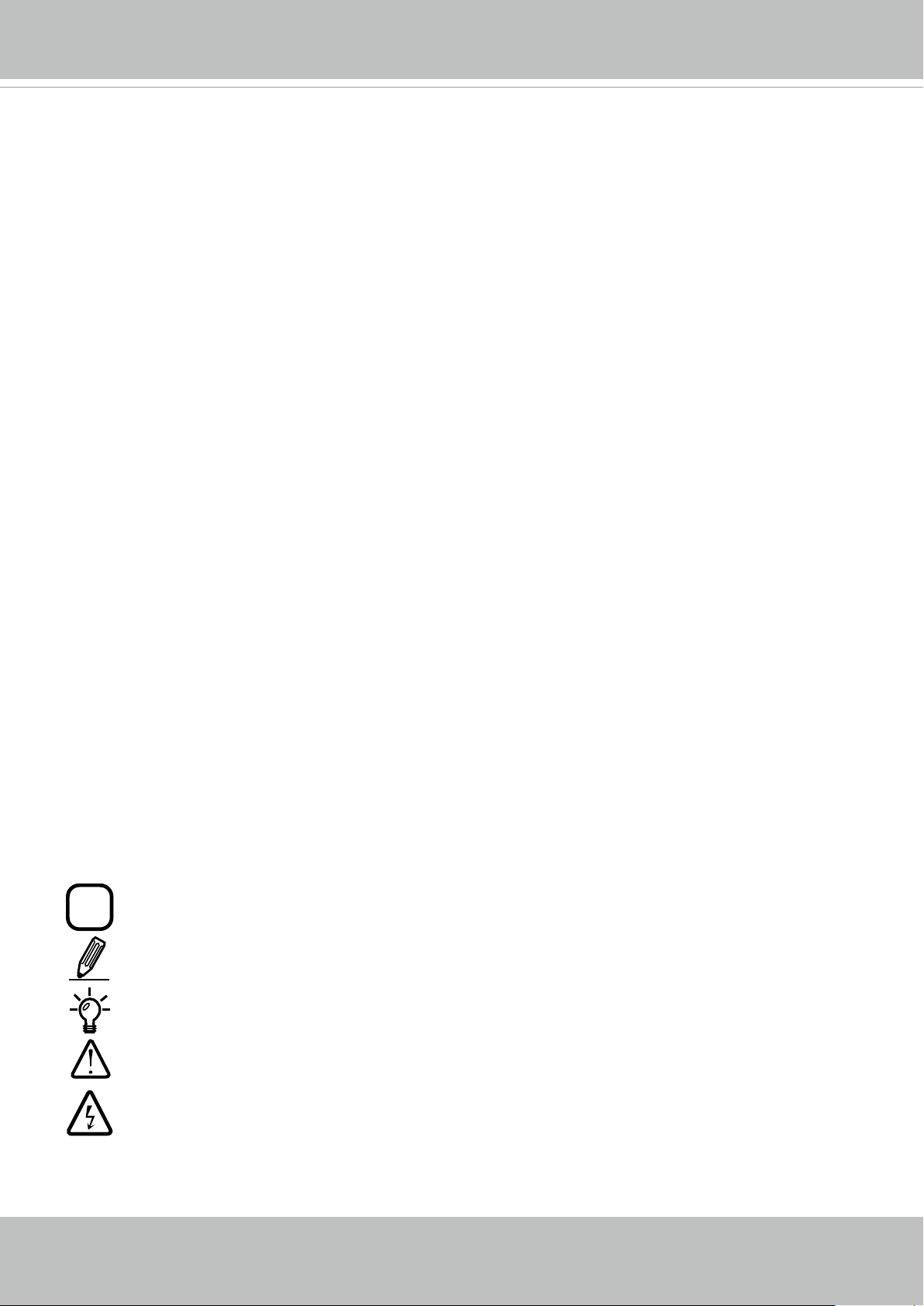
Symbols and Statements in this Document
INFORMATION: provides important messages or advices that might help prevent inconvenient
or problem situations.
NOTE: Notices provide guidance or advices that are related to the functional integrity of the
machine.
Tips: Tips are useful information that helps enhance or facilitae an installation, function, or
process.
WARNING: or IMPORTANT:: These statements indicate situations that can be dangerous or
hazardous to the machine or you.
Electrical Hazard: This statement appears when high voltage electrical hazards might occur
to an operator.
User's Manual - 5
VIVOTEK
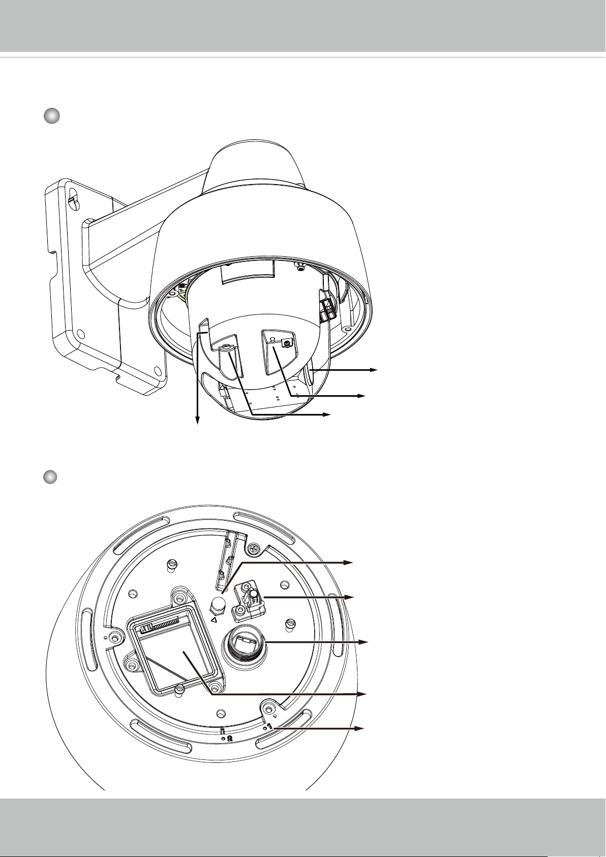
Physical Description
Outer View
This drawing shows a camera with its dome
cover removed.
Lens
Inner View
Reset Button
MicroSD card slot
Status LED
IR unit connector
Safety wire hook
LAN connector
6 - User's Manual
I/O combo connector
Alignment marks
VIVOTEK
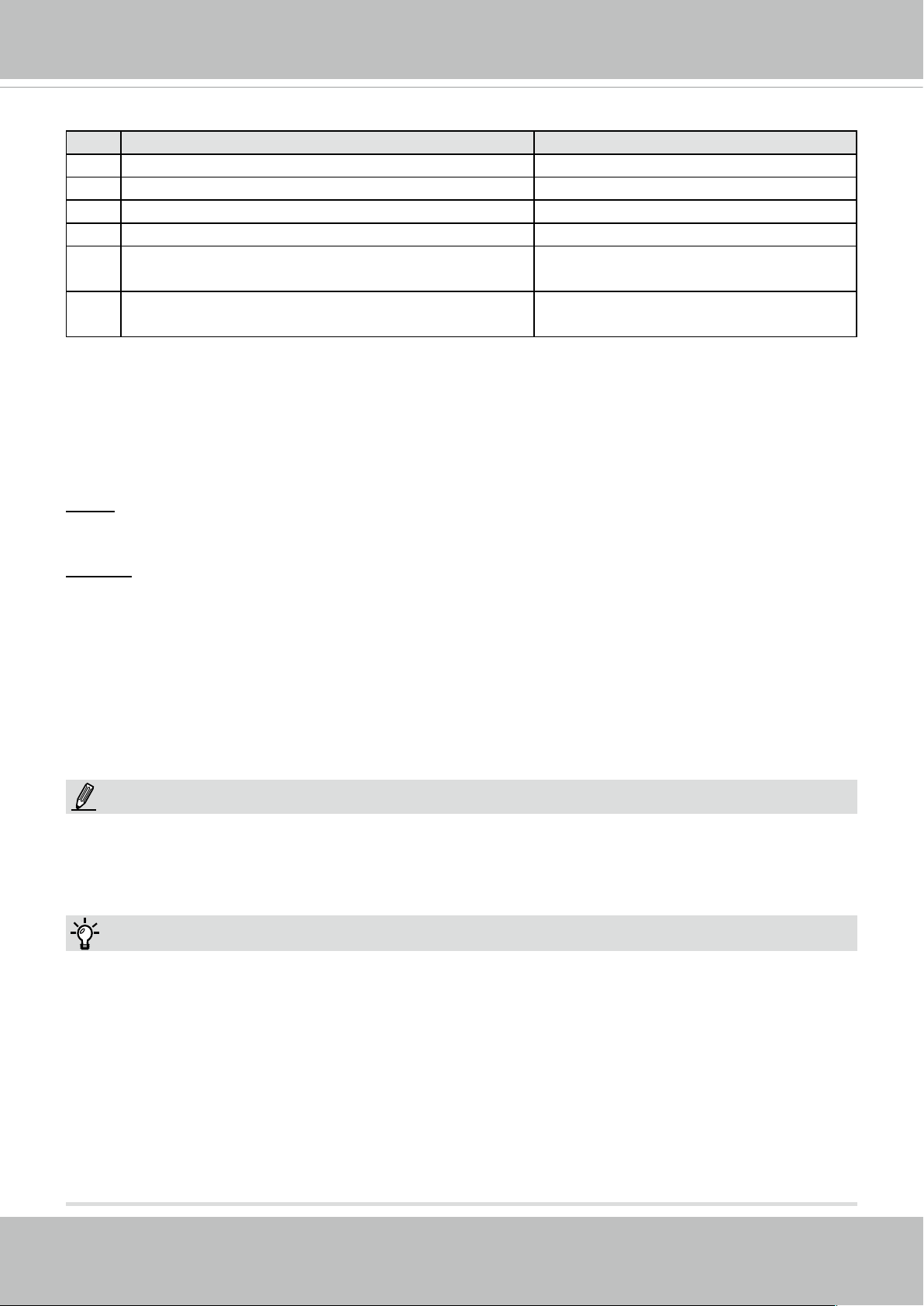
Status LED
Item LED status Description
1 Steady red Power on and system booting
Red LED OFF Power off
2 Steady red & Green blinking every 1 sec. Network normal (heartbeat)
Steady red & Green LED OFF Network failed
3 Red blinking every 0.15 sec. & Green blinking
Upgrading rmware
every 1 sec.
4 Red blinking every 0.15 sec. & Green blinking
Restoring default
every 0.15 sec.
Hardware Reset
The reset button is used to reset the system or to restore the factory default settings. Sometimes
resetting the system can return the camera to normal operation. If the system problems remain
after reset, restore the factory settings and install again.
Reset: Press and release the reset button with a paper clip or thin object. Wait for the Network
Camera to reboot.
Restore: Press and hold the reset button for at least ten seconds to restore system defaults.
Note that all settings will be restored to factory defaults.
SD/SDHC/SDXC Card Capacity
This network camera is compliant with SD/SDHC/SDXC 32GB, 64GB, and other preceding
standard SD cards.
NOTE:
1. This equipment is only to be connected to PoE networks without routing to outside plants.
2. For PoE input, use only UL listed I.T.E. with PoE output.
Tips:
1. If you forget the root (administrator) password for the camera, you can restore the camera
defaults by pressing the reset button for longer than 5 seconds.
2. If DHCP is enabled in your network, and the camera cannot be accessed, run the IW2 utility
to search the network. If the camera has been congured with a xed IP that does not comply
with your local network, you may see its default IP 169.254.x.x. If you still cannot find the
camera, you can restore the camera to its factory defaults. The factory default is DHCP client.
3. If you change your network parameters, e.g., added a camera via a connection to a LAN
card, re-start the IW2 utility.
User's Manual - 7
VIVOTEK
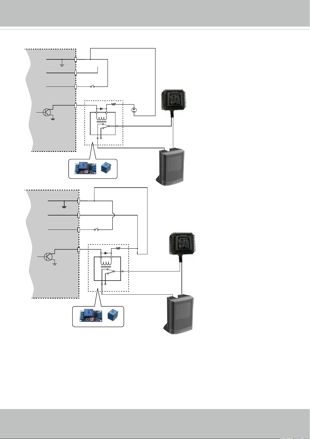
DI/DO Diagram
DI-
DO+
VDC
BJT transistor
DI+
DO-
DO+
DI-
DI+
Switch
NO NC
Switch
Relay
VDC
External
power source
AC
Source
External
device
AC
BJT transistor
DO-
NO NC
Relay
Source
External
device
1. The DO+ pin provides 12V output voltage, and the max. load is 50mA.
2. The max. voltage for DO- pins is 80VDC (External power).
In order to control AC devices, the above diagram can be taken in consideration. The diagram
uses a relay to control the ON/OFF condition of the AC device.
3. An external relay can be triggered by using DO+ or by an external power source, depending
on the type of relay you use.
4. In case of using an individual relay (instead of using a relay module), for protection against
voltage or current spikes, a transient voltage suppression diode must be connected in parallel
with the inductive load.
8 - User's Manual
VIVOTEK
Hardware Installation
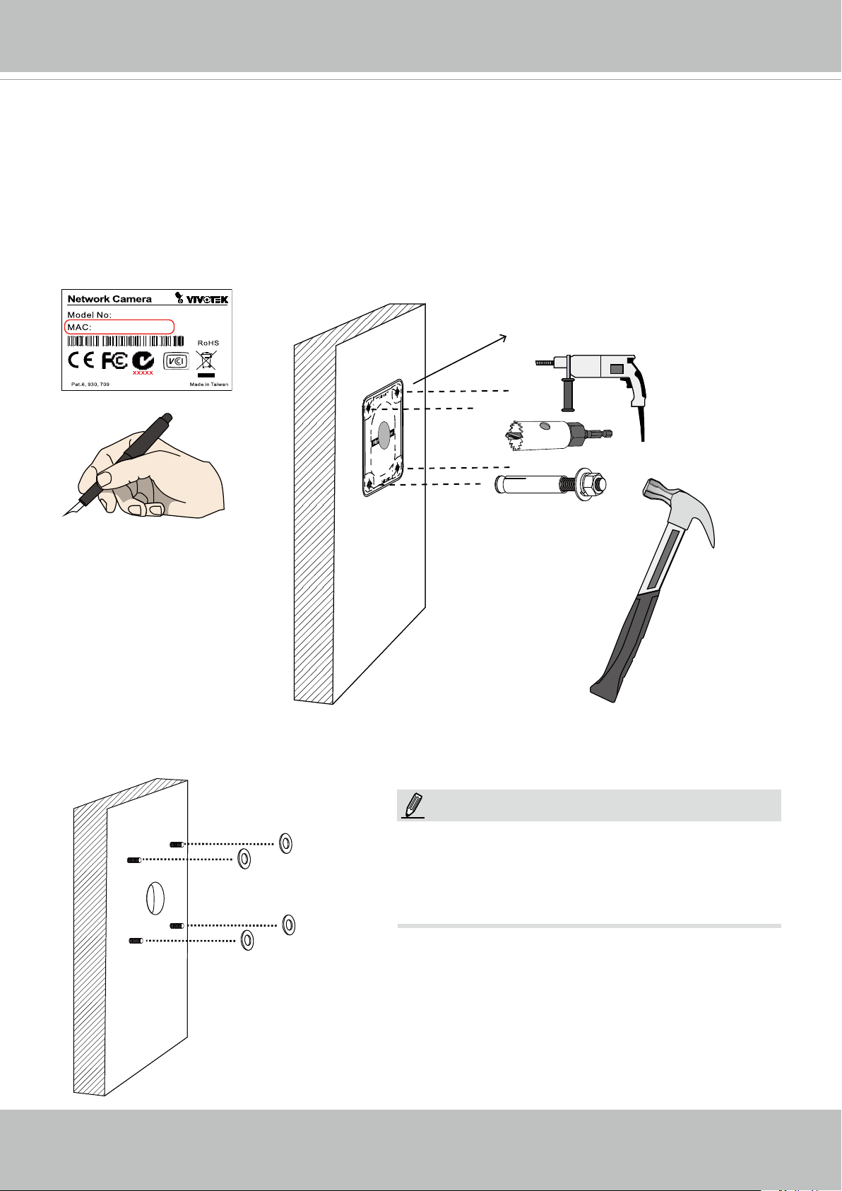
1. Jot down the camera's MAC address for later reference.
2. The camera weighs 3kg. Select a rigid mounting location to prevent vibration to the camera.
Attach the alignment sticker to the wall.
3. Drill 4 pilot holes (9.5mm in diameter and 4cm deep) into the wall, and then hammer in
threaded anchors. Note that you should hammer the anchors with hex nuts on them so that
the threaded poles will not be deformed! If preferred, drill another hole for routing cables.
SDXXXX
0002D10766AD
Ø 9.5mm or 3/8”
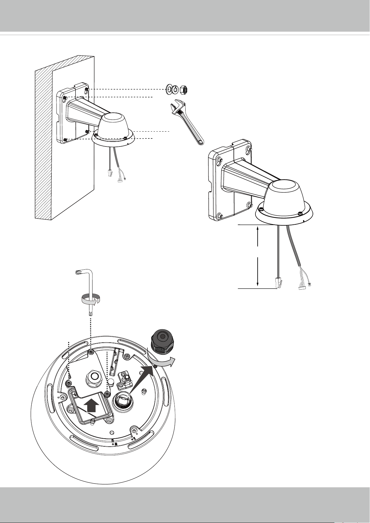
4. Remove the hex nuts, washers, and leave one washer on each of the threaded poles.
NOTE:
1. IO wires are user-supplied.
2. Avoid touching the circuit boards to prevent
damage by electro static discharge.
3. Use CAT5e, CAT6 cables only.
User's Manual - 9
VIVOTEK
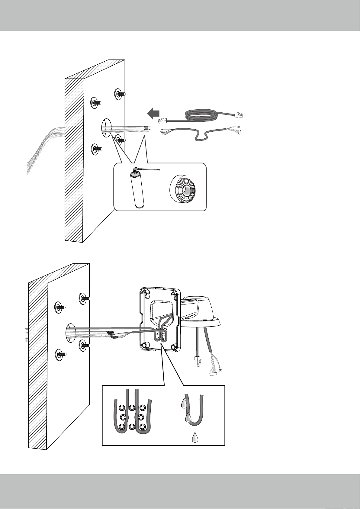
5. Connect power or I/O wires, and use foam tapes or seal foam to ensure the back-end
connection is waterproof.
6. Route your I/O combo and Ethernet cables along the routing guide poles to form drip loops.
10 - User's Manual
LAN I/O combo
7. Secure the bracket to wall.
VIVOTEK
The cable length hanging on the outside of
the bracket should be 15cm.
8. Remove the cable gland from the LAN port. If I/O wires or
24V power are preferred, use the T20 L-wrench to remove
the top cover on the I/O connectors.
T20
15cm
User's Manual - 11
VIVOTEK
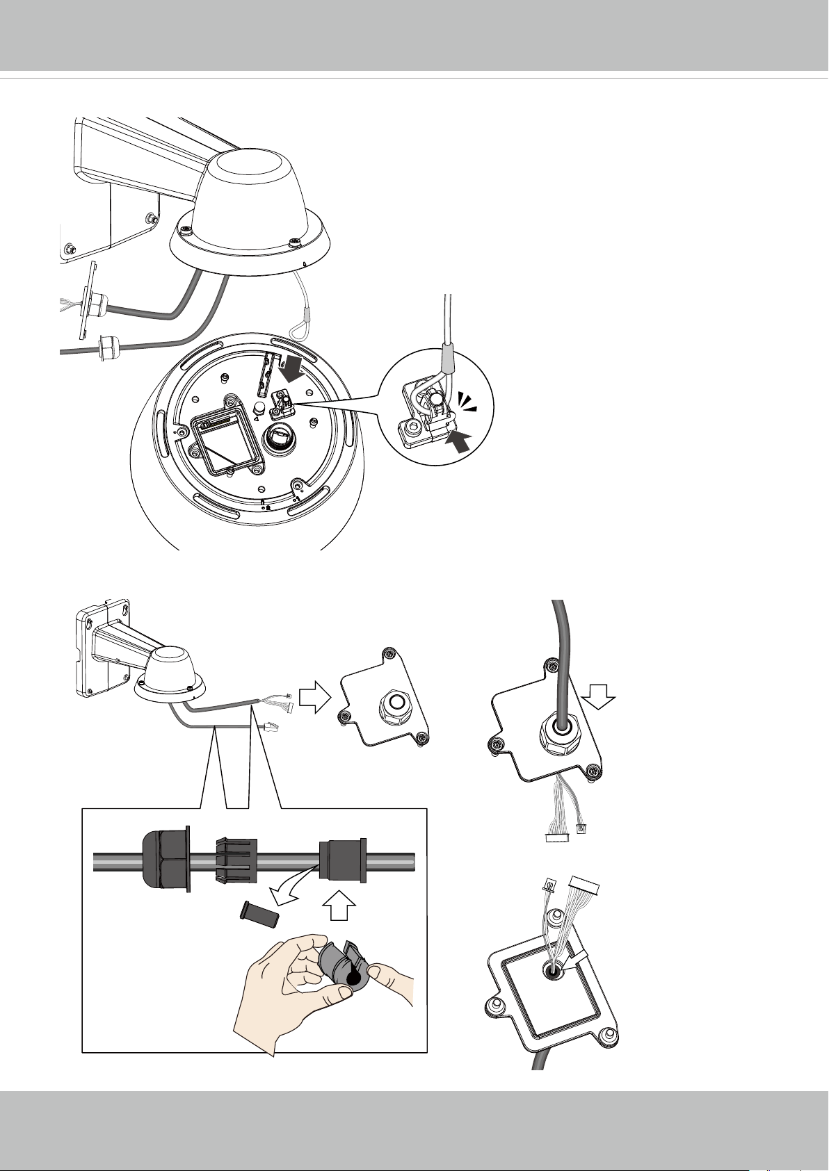
9. Hook up the safety wire between the bracket and the camera.
10. Install the components of the waterproof cable gland to the Ethernet and I/O combo cables.
The outer jacket of
the combo cable is
ush with cabling
hole.
12 - User's Manual

11. Connect the I/O wire headers to camera and then secure the top cover.
T20
VIVOTEK
12. Connect the Ethernet cable (along with its cable gland) to the camera.
NOTE:
To disconnect a LAN cable, loosen the cable gland
and pull the cable against the socket wall towards
the side of the locking tab.
IMPORTANT:
Make sure all waterproof cable glands have
been properly installed. Water leakage will cause
irrepairable damage to the camera.
User's Manual - 13
VIVOTEK
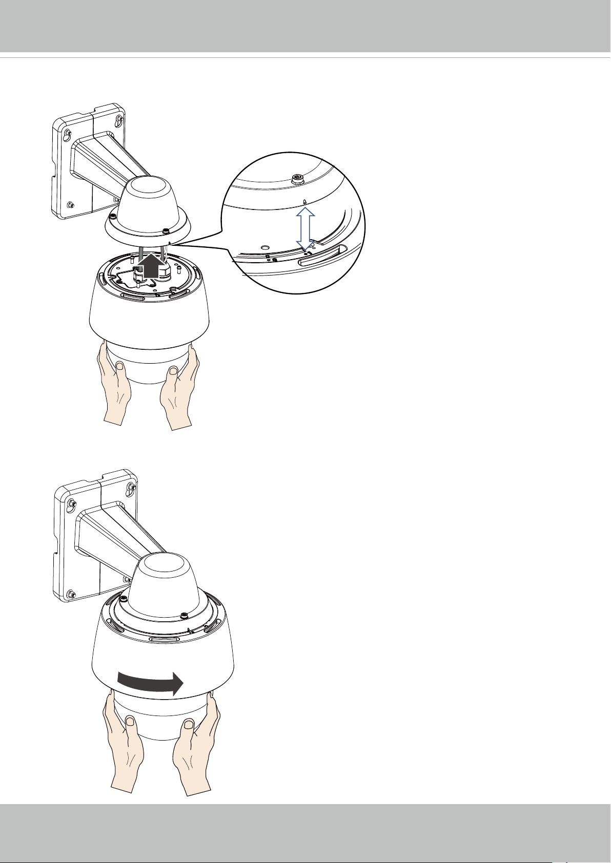
13. Install the camera to bracket by aligning the mark on bracket with the #1 marking on the cam-
era.
2
14. Turn the camera clockwise. The camera should be locked in place.
1
14 - User's Manual
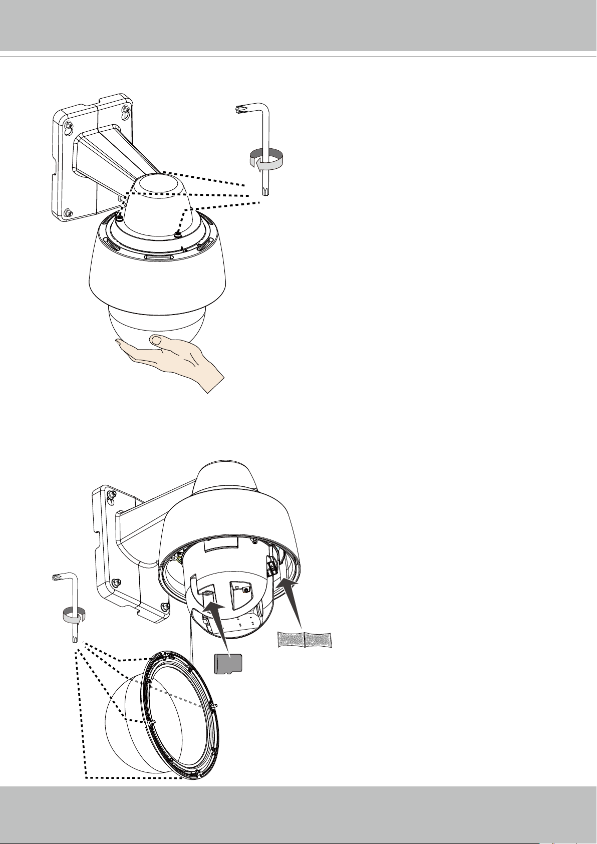
15. Secure the connection using the T25 L-wrench from the top.
T25
VIVOTEK
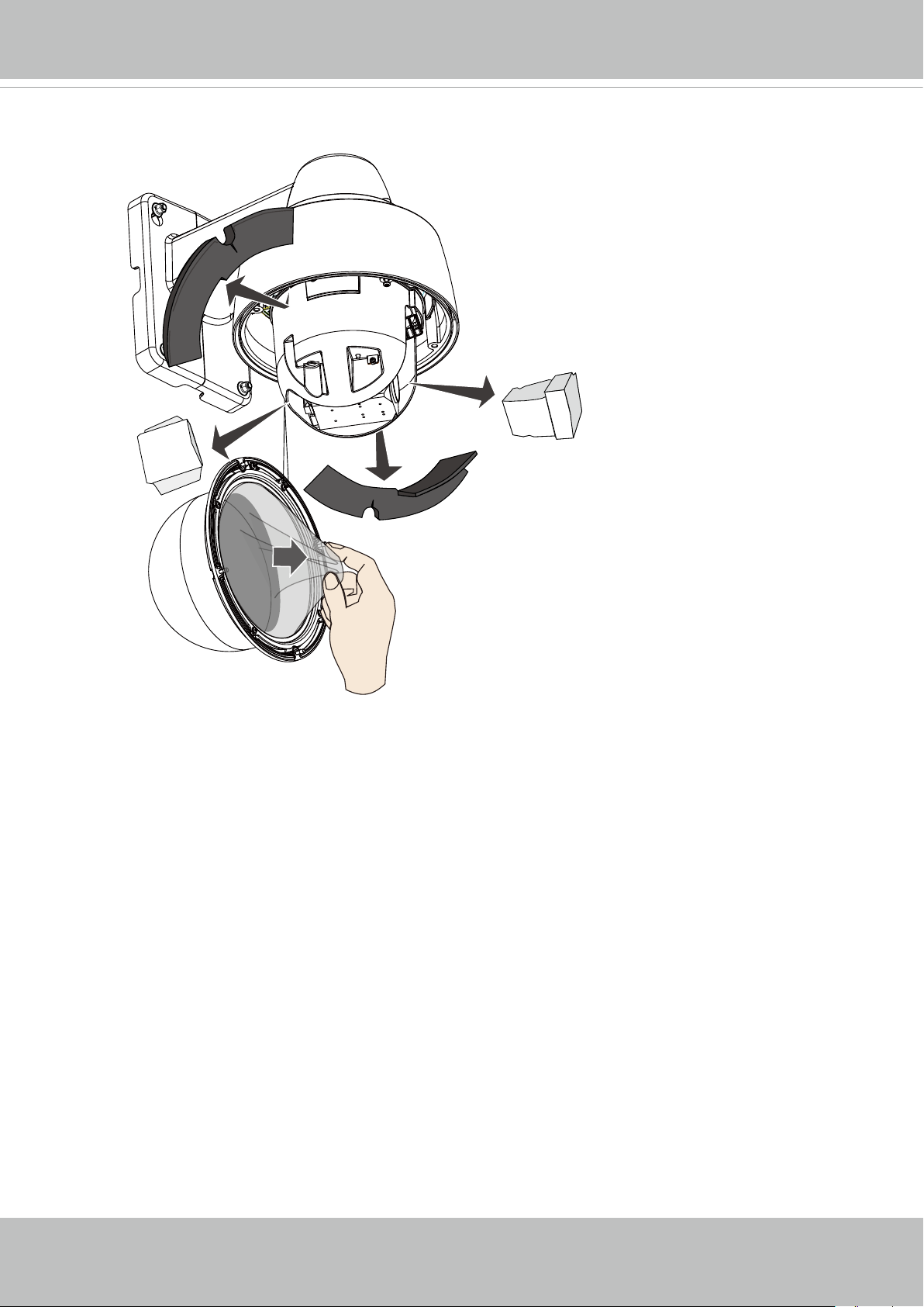
16. Open the dome cover using the T20 L-wrench. Install a microSD card, and replace the desic-
cant bag on the inner side of camera chassis.
T20
icro
M
SD
User's Manual - 15
VIVOTEK
17. Remove the foam blocks in the chassis, and the front and rear of the lens module. Also re-
move the plastic sheet from the inside of the dome cover.
18. When done, secure the dome cover using the T20 L-wrench.
16 - User's Manual
VIVOTEK
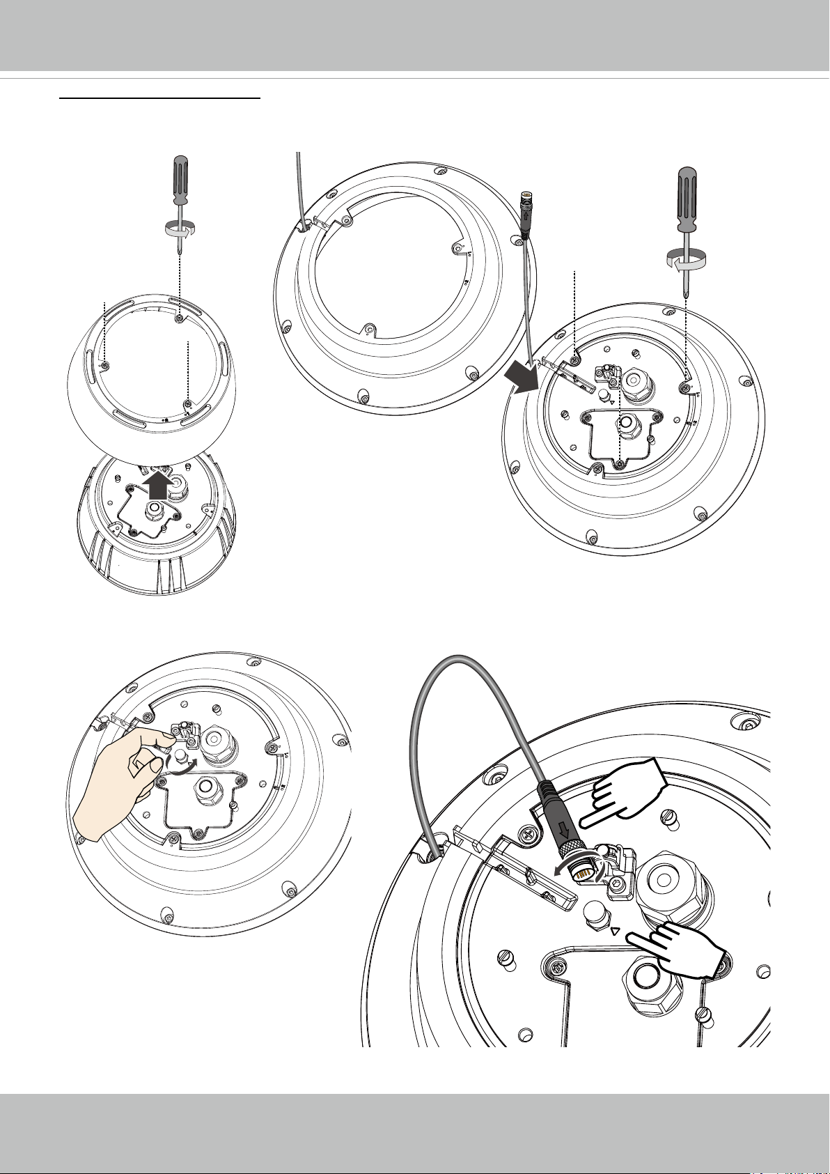
IR Unit Installation
1. Remove the sun shield from the camera, and then install the IR unit by driving 3 Phillips
screws. Align the cable with the routing groove on camera.
2. Remove the metal cap on the IR unit connector. Install the connector by aligning the indicators. Tighten up the connector by turning the metal coupling ring clockwise.
User's Manual - 17
VIVOTEK
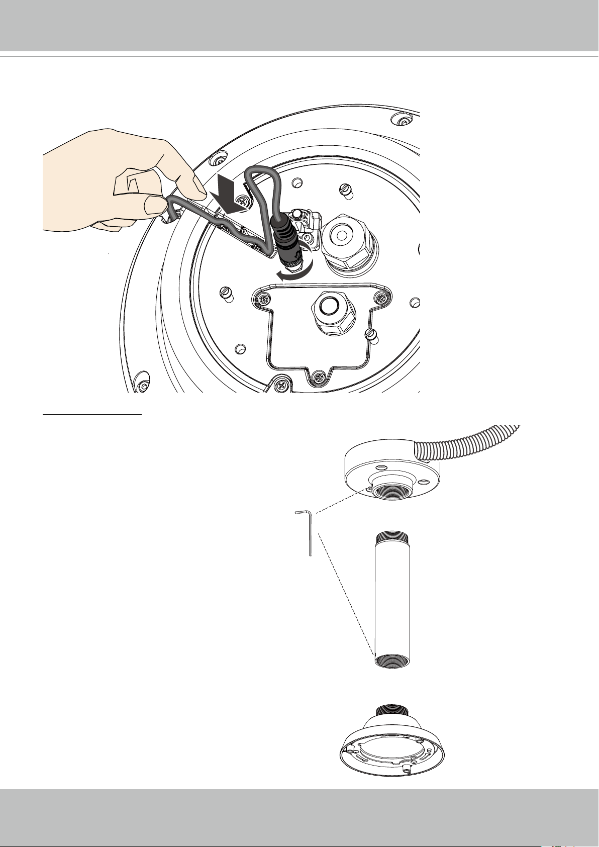
3. Pess the cable into the routing groove so that the cable will not get in the way when installing
the camera.
Pendant Mount
The camera can also be mounted through a
pendant mount combination as shown below.
The rest of the installation prcedure is the same
as described above.
3/4”
AM-118
AM-116/117
18 - User's Manual
AM-529
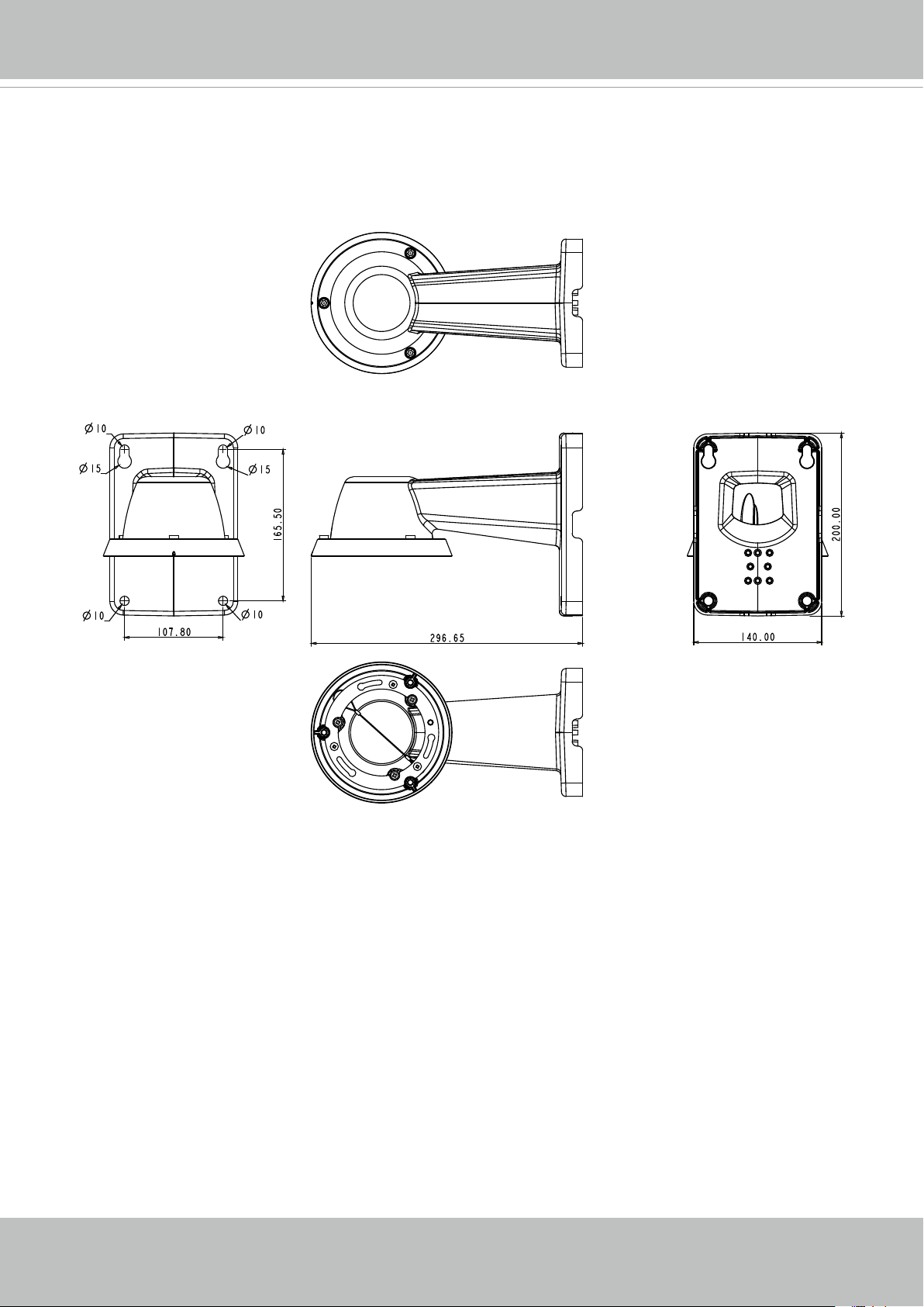
Mechanical Dimensions
Shown below are the dimensions of the wall mount bracket and its mounting holes:
VIVOTEK
You can nd the installation instructions on VIVOTEK’s website for other options such as parapet mount: http://www.vivotek.com/web/product/accessories.aspx
User's Manual - 19

VIVOTEK
Network Deployment
Setting up the Network Camera over the Internet
There are several ways to set up the Network Camera over the Internet. The rst way is to set
up the Network Camera behind a router. The second way is to utilize a static IP. The third way is
to use PPPoE.
Internet connection via a router
Before setting up the Network Camera over the Internet, make sure you have a router and follow
the steps below.
1. Connect your Network Camera behind a router, the Internet environment is illustrated below.
Regarding how to obtain your IP address, please refer to Software Installation on page 23 for
details.
IP address : 192.168.0.3
Subnet mask : 255.255.255.0
Default router : 192.168.0.1
IP address : 192.168.0.2
Subnet mask : 255.255.255.0
Default router : 192.168.0.1
Internet
Cable or DSL Modem
WAN (Wide Area Network )
Router IP address : from ISP
LINK
POWER
COLLISION
RECEIVE
1
2
PARTITION
3
4
5
LAN (Local Area Network)
Router IP address : 192.168.0.1
2. In this case, if the Local Area Network (LAN) IP address of your Network Camera is
192.168.0.3, please forward the following ports for the Network Camera on the router.
■ Secondary HTTP port: 8080
■ RTSP port: 554
■ RTP port for audio: 5558
■ RTCP port for audio: 5559
■ RTP port for video: 5556
■ RTCP port for video: 5557
If you have changed the port numbers on the Network page, please open the ports accordingly
on your router. For information on how to forward ports on the router, please refer to your
router’s user’s manual.
3. Find out the public IP address of your router provided by your ISP (Internet Service Provider).
Use the public IP and the secondary HTTP port to access the Network Camera from the
20 - User's Manual
VIVOTEK
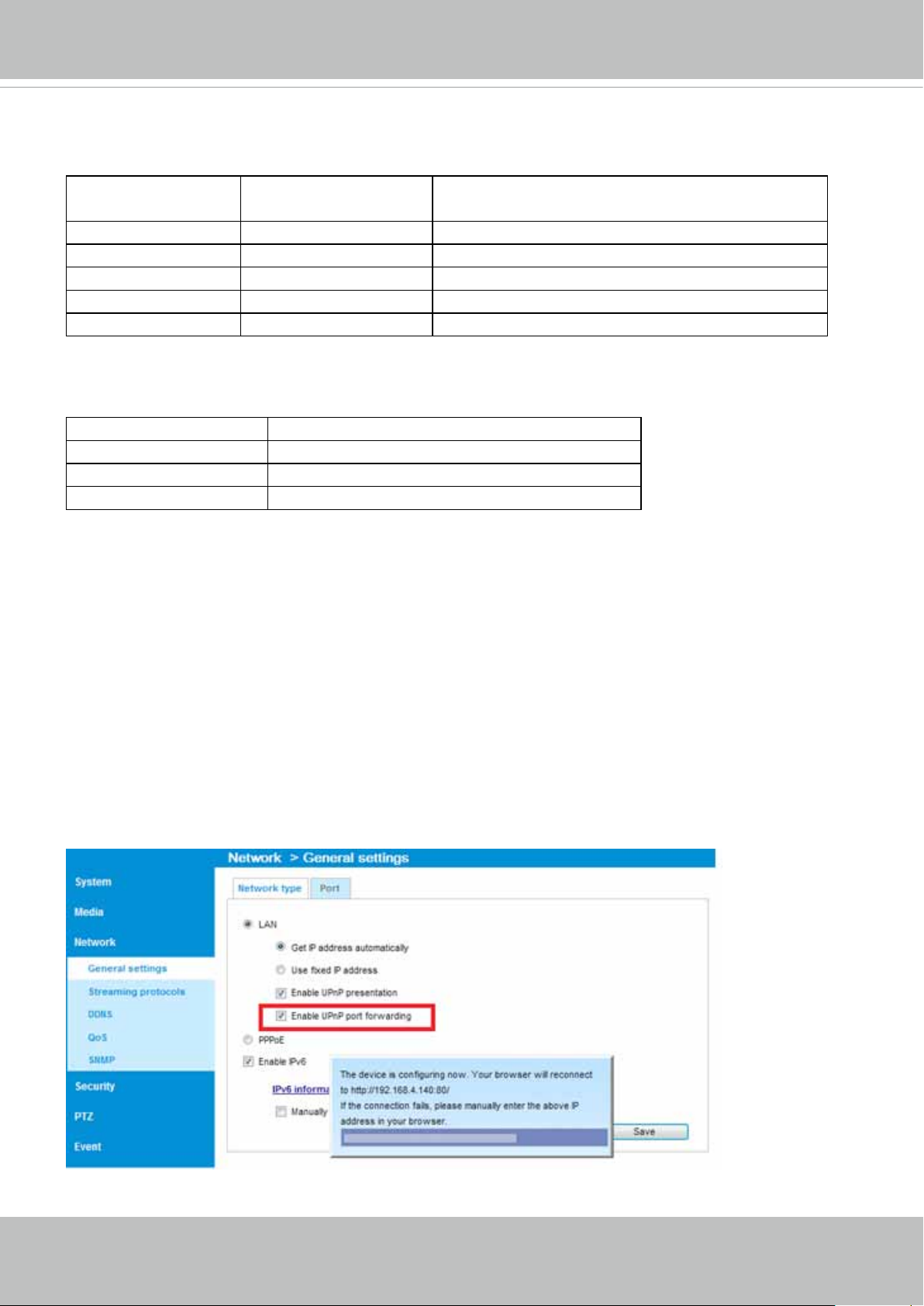
Internet. Please refer to Network Type on page 60 for details.
For example, your router and IP settings may look like this:
Device IP Address: internal
port
IP Address: External Port (Mapped port on the
router)
Public IP of router 122.146.57.120
LAN IP of router 192.168.2.1
Camera 1 192.168.2.10:80 122.146.57.120:8000
Camera 2 192.168.2.11:80 122.146.57.120:8001
... ... ...
Congure the router, virtual server or rewall, so that the router can forward any data coming
into a precongured port number to a network camera on the private network, and allow data
from the camera to be transmitted to the outside of the network over the same path.
From Forward to
122.146.57.120:8000 192.168.2.10:80
122.146.57.120:8001 192.168.2.11:80
... ...
When properly congured, you can access a camera behind the router using the HTTP request
as follows: http://122.146.57.120:8000
If you change the port numbers on the Network conguration page, please open the ports
accordingly on your router. For example, you can open a management session with your router
to congure access through the router to the camera within your local network. Please consult
your network administrator for router conguration if you have troubles with the conguration.
For more information with network conguration options (such as that of streaming ports),
please refer to Conguration > Network Settings. VIVOTEK also provides the automatic port
forwarding feature as an NAT traversal function with the precondition that your router must
support the UPnP port forwarding feature.
User's Manual - 21
VIVOTEK
Internet connection with static IP
Choose this connection type if you are required to use a static IP for the Network Camera.
Please refer to LAN on page 60 for details.
Internet connection via PPPoE (Point-to-Point over Ethernet)
Choose this connection type if you are connected to the Internet via a DSL Line. Please refer to
PPPoE on page 70 for details.
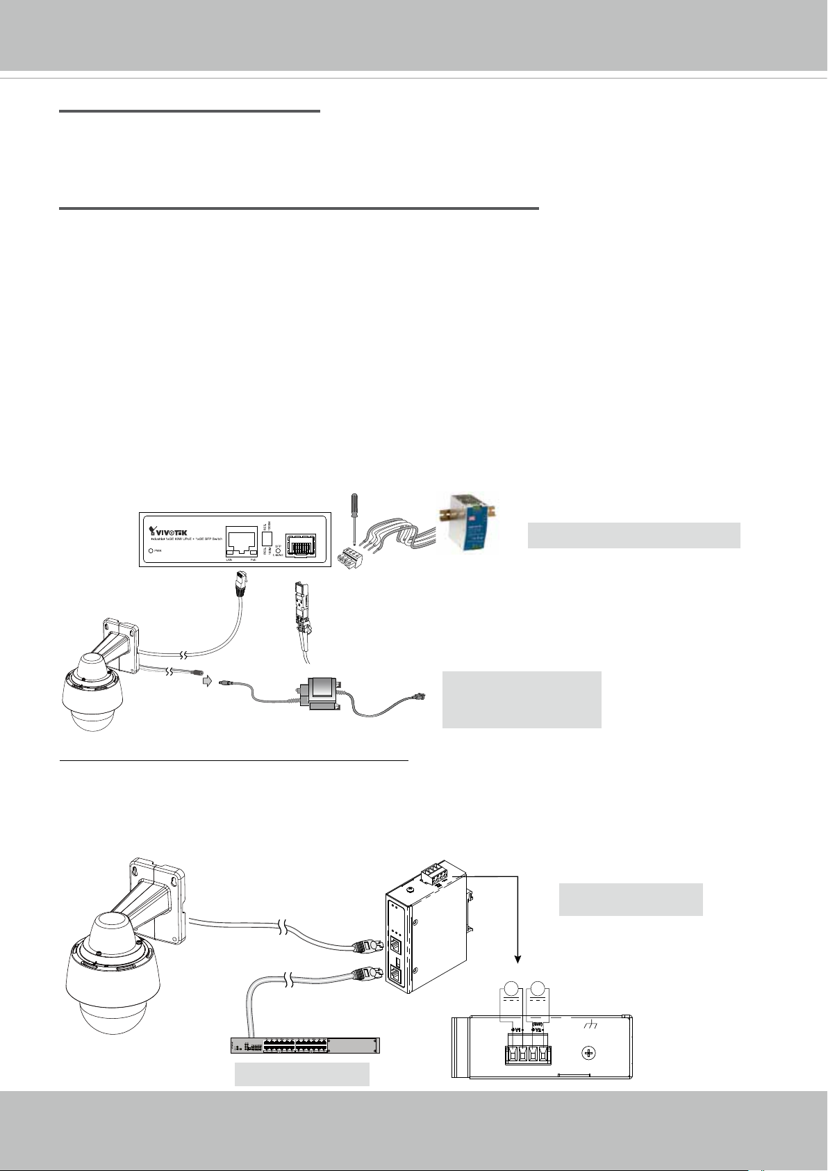
General Connection
1. Connect the Network Camera's Ethernet cable (CAT5e) to a PoE Plus switch. A 30W PoE
output port alone can not drive the onboard heater, and hence if using the PoE switch alone,
the application does not apply in low-temperature condition. A 60W PoE plus or UPoE switch
can drive the camera when it is working under a temperature lower than -10ºC.
2. Connect the power wires to an AC 24V power adaptor (user-supplied). The AC 24V adapter
can drive the camera and the onboard heater.
You can connect both power sources for redundancy in power supply.
UPoE Switch (60W output)
AC-to-DC power
LC
100~240 VAC IN
and / or
AC 24V 3.5A
Adapter (Separately
purchasedied)
Power over Ethernet (High Power PoE)
When using a non-PoE switch
Use a High Power PoE power injector (separately purchased) capable of 60W output or higher
to connect between the Network Camera and a non-PoE switch. Sufcient power is required for
low temperature conditions when the onboard heater is activated.
22 - User's Manual
Non-PoE Switch
48 ~ 56V DC
+-+
High Power PoE
Power Injector
-
Chassis Ground
VIVOTEK
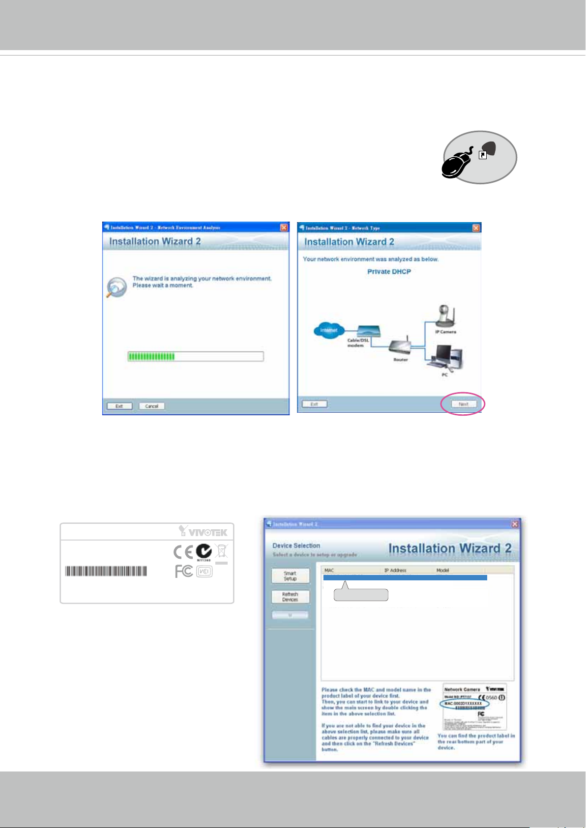
Software Installation
Installation Wizard 2 (IW2), free-bundled software included on the product CD, helps you set up
your Network Camera on the LAN.
IW
1. Install IW2 under the Software Utility directory from the software CD.
Double click the IW2 shortcut on your desktop to launch the program.
2. The program will conduct an analysis of your network environment.
After your network environment is analyzed, please click Next to continue the program.
2
Installation
Wizard 2
3. The program will search for all VIVOTEK network devices on the same LAN.
4. After a brief search, the main installer window will prompt. Double-click on the MAC and
model name which matches the product label on your device to connect to the Network
Camera via a web browser.
Network Camera
Model No: SD9361
MAC:0002D1730202
This device complies with part 15 of the FCC rules. Operation is subject to the following two conditions:
(1)This device may not cause harmful interference, and
(2) this device must accept any interference received, including interference that may cause undesired operation.
Pat. 6,930,709
R o HS
Made in Taiwan
00-02-D1-73-02-02 192.168.5.151 SD9361
0002D1730202
User's Manual - 23
VIVOTEK
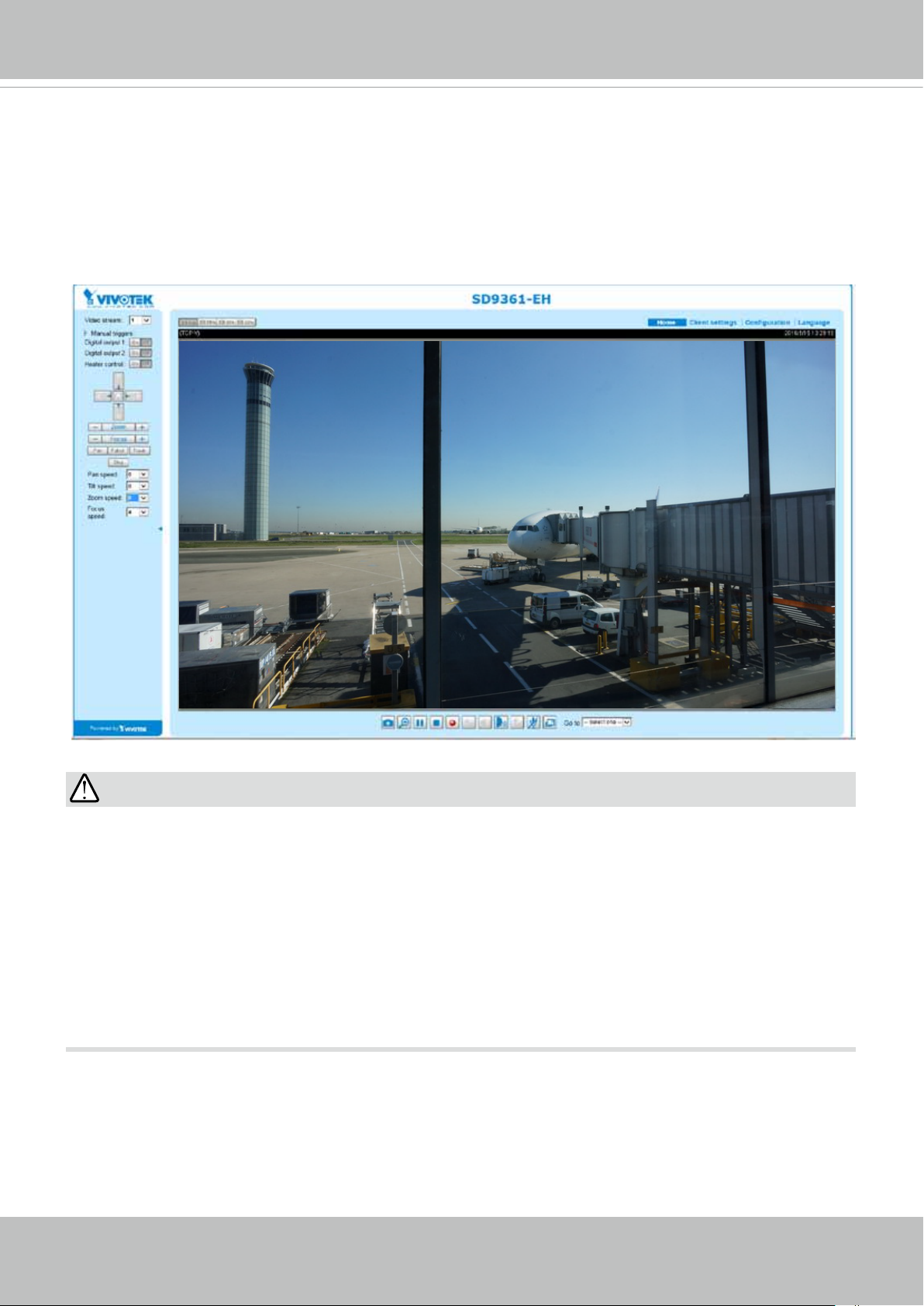
Ready to Use
1. A browser session with the Network Camera should prompt as shown below.
2. You should be able to see live video from your camera. You may also install the 32-channel
recording software from the software CD in a deployment consisting of multiple cameras. For
its installation details, please refer to its related documents.
30x
IMPORTANT:
Currently the Network Camera utilizes a 32-bit ActiveX plugin. You CAN NOT open a
•
management/view session with the camera using a 64-bit IE browser.
If you encounter this problem, try execute the Iexplore.exe program from C:\Windows\
•
SysWOW64. A 32-bit version of IE browser will be installed.
On Windows 7, the 32-bit explorer browser can be accessed from here: C:\Program Files
•
(x86)\Internet Explorer\iexplore.exe
If you experience compatibility issues between the plug-in control, you may try to uninstall
•
the Camera Stream Controller located in: C:/Program Files (x86)/Camera Stream Controller.
24 - User's Manual
VIVOTEK
Accessing the Network Camera
This chapter explains how to access the Network Camera through web browsers, RTSP players,
3GPP-compatible mobile devices, and VIVOTEK recording software.
Using Web Browsers
Use Installation Wizard 2 (IW2) to access to the Network Cameras on the LAN.
If your network environment is not a LAN, follow these steps to access the Netwotk Camera:
1. Launch your web browser (e.g., Microsoft
2. Enter the IP address of the Network Camera in the address eld. (A temporary IP will be
generated for the camera. Find it in your Network Neighborhood). Press Enter.
3. Live video will display in your web browser.
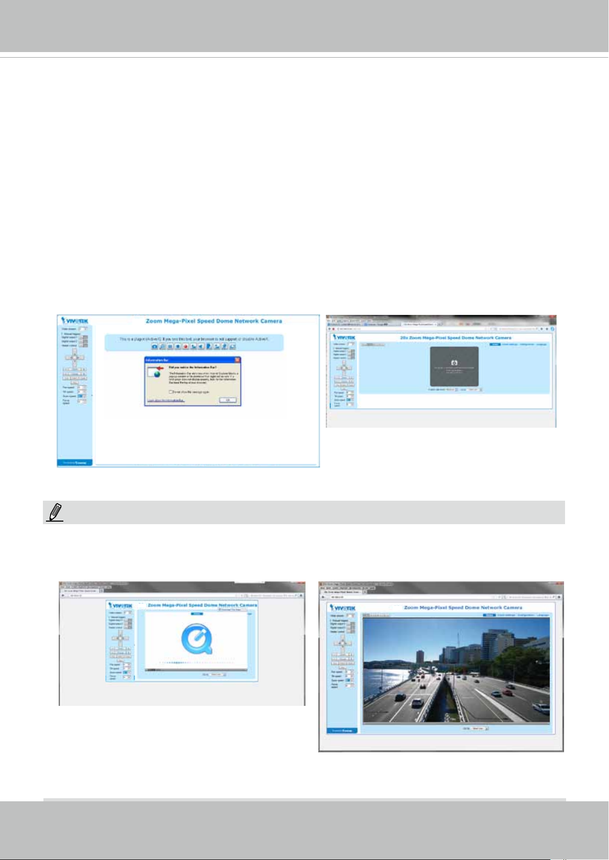
4. If it is the rst time installing the VIVOTEK network camera, an information bar will pop up as
shown below. Follow the instructions to install the required plug-in on your computer.
30x
®
Internet Explorer or Mozilla Firefox).
NOTE:
For Mozilla Firefox or Netscape users, your browser will use Quick Time to stream live video.
If you do not have Quick Time on your computer, please download Quick Time from Apple Inc's
website, and then launch your web browser.
28x
30x
User's Manual - 25
VIVOTEK
► By default, the Network Camera is not password-protected. To prevent unauthorized access,
it is highly recommended to set a password for the Network Camera.
For more information about how to enable password protection, please refer to Security on
page 87. .
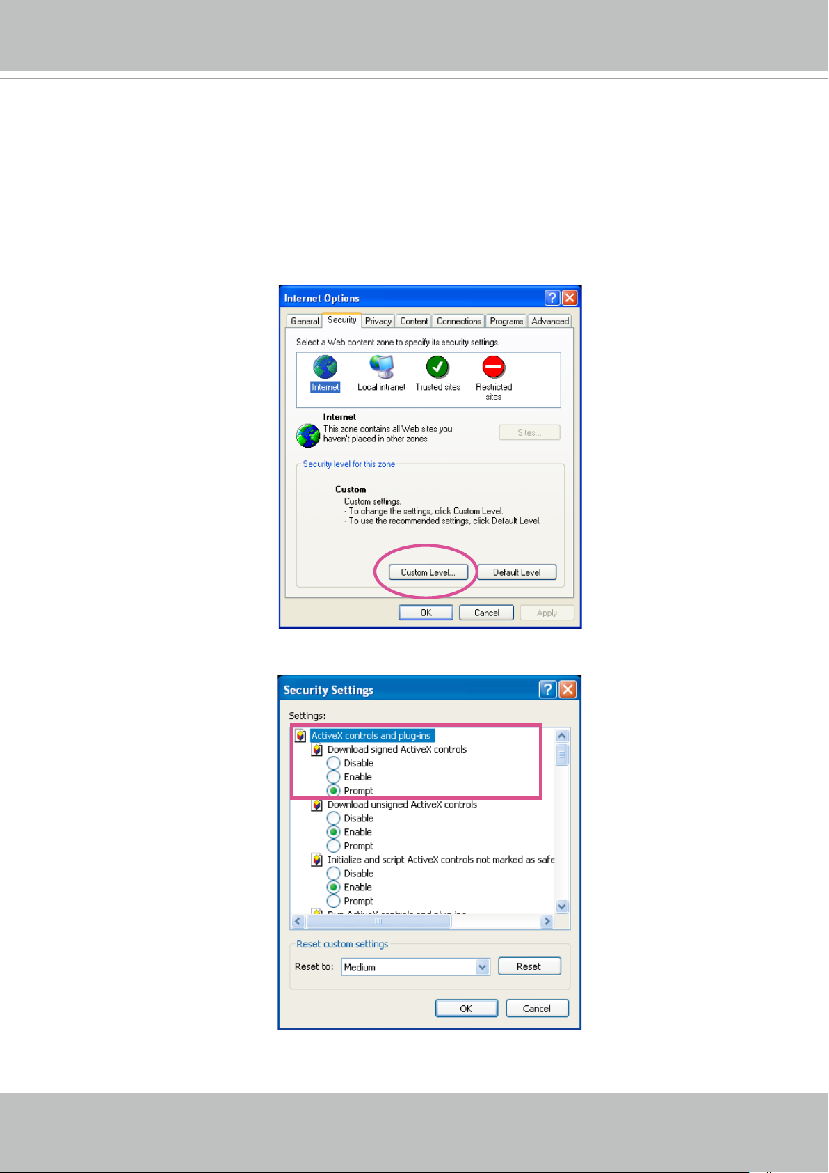
► If you see a dialog box indicating that your security settings prohibit running ActiveX
®
Controls, please enable the ActiveX
Controls for your browser.
®
1. Choose Tools > Internet Options > Security > Custom Level.
2. Look for Download signed ActiveX
®
controls; select Enable or Prompt. Click OK.
3. Refresh your web browser, then install the ActiveX
complete installation.
®
control. Follow the instructions to
26 - User's Manual
VIVOTEK
Using RTSP Players
To view the H.265/H.264 streaming media using RTSP players, you can use one of the following
players that support RTSP streaming.
Quick Time Player
VLC Media Player
VLC media player
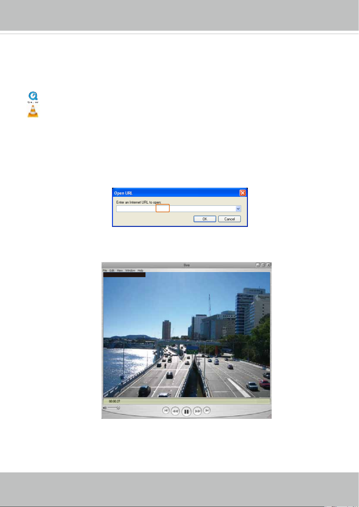
1. Launch the RTSP player.
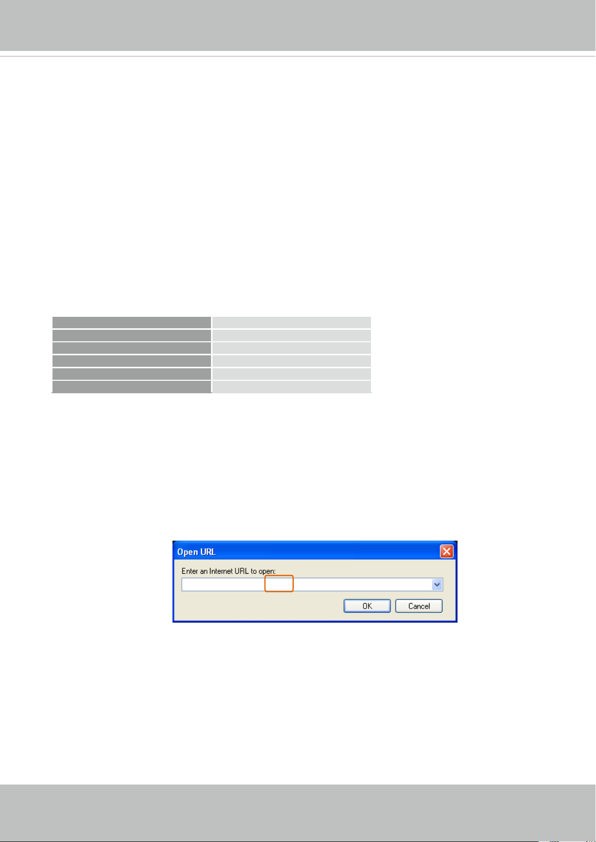
2. Choose File > Open URL. An URL dialog box will pop up.
mpegable Player
3. The address format is rtsp://<ip address>:<rtsp port>/<RTSP streaming access name for
pvPlayer
stream1 or stream2>
As most ISPs and players only allow RTSP streaming through port number 554, please set the
RTSP port to 554. For more information, please refer to RTSP Streaming on page 78.
For example:
rtsp://192.168.5.151:554/live.sdp
4. The live video will be displayed in your player.
For more information on how to configure the RTSP access name, please refer to RTSP
Streaming on page 78 for details.
Video 16:38:01 2011/03/25
User's Manual - 27
VIVOTEK
Using 3GPP-compatible Mobile Devices
To view the streaming media through 3GPP-compatible mobile devices, make sure the Network
Camera can be accessed over the Internet. For more information on how to set up the Network
Camera over the Internet, please refer to Setup the Network Camera over the Internet on page
20.
To utilize this feature, please check the following settings on your Network Camera:
1. Because most players on 3GPP mobile phones do not support RTSP authentication, make
sure the authentication mode of RTSP streaming is set to disable.
For more information, please refer to RTSP Streaming on page 78.
2. As the the bandwidth on 3G networks is limited, you will not be able to use a large video size.
Please set the video and audio streaming parameters as listed below.
For more information, please refer to Stream settings on page 62.
Video Mode MPEG-4
Frame size 176 x 144
Maximum frame rate 5 fps
Intra frame period 1S
Video quality (Constant bit rate) 40kbps
Audio type (GSM-AMR) 12.2kbps
3. As most ISPs and players only allow RTSP streaming through port number 554, please set
the RTSP port to 554. For more information, please refer to RTSP Streaming on page 78.
4. Launch the player on the 3GPP-compatible mobile devices (ex. Real Player).
5. Type the following URL commands into the player.
The address format is rtsp://<public ip address of your camera>:<rtsp port>/<RTSP streaming
access name for stream 3>.
For example:
rtsp://192.168.5.151:554/live.sdp
28 - User's Manual
VIVOTEK
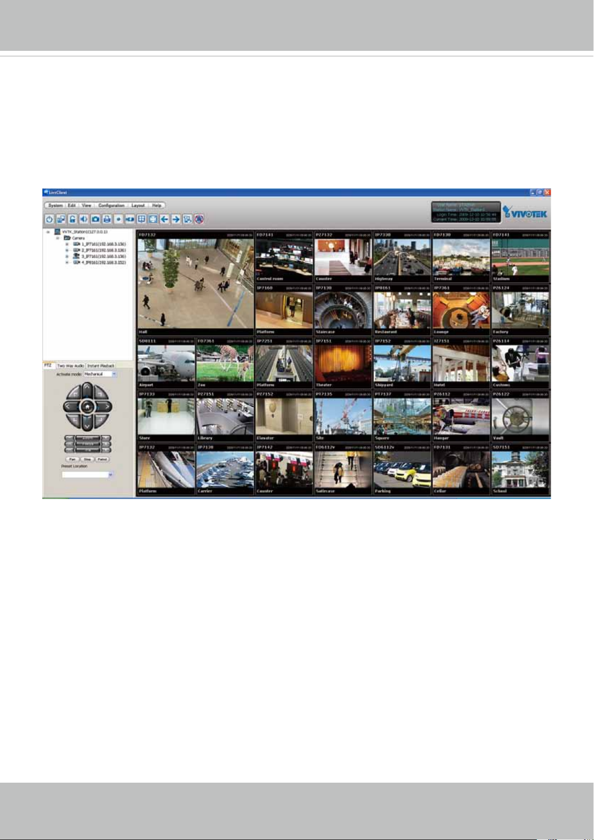
Using VIVOTEK Recording Software
The product software CD also contains recording software, allowing simultaneous monitoring
and video recording for multiple Network Cameras. Please install the recording software; then
launch the program to add the Network Camera to the Channel list. For detailed information
about how to use the recording software, please refer to the user’s manual of the software or
download it from http://www.vivotek.com.
User's Manual - 29
VIVOTEK
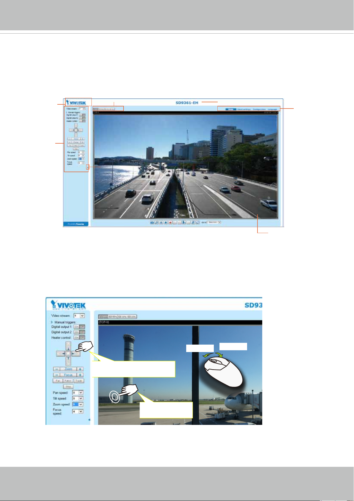
Main Page
This chapter explains the layout of the main page. It is composed of the following sections:
VIVOTEK INC. Logo, Host Name, Camera Control Area, Configuration Area, and Live Video
Window.
VIVOTEK INC.
Logo
Camera Control
Area
Resize Buttons
Hide Button
Host Name
Configuration
Area
Live View Window
Mouse and Screen Control
In addition to the use of a joystick, mouse control is also supported by the web session. You can click
on any spot on the screen to move camera's eld of view to that direction. To pan 360 degrees, you can
click and hold down the left mouse button when clicking a PTZ button. The same applies to arrow keys,
Zoom, and Focus buttons on the PTZ panel.
Zoom In
Click and hold down the
button to continue turning
Zoom Out
Click to bring to
center of view
Note that if your screen control malfunctions, it is possible that the CPU of your current view station can
not cope with the HD video feeds or that an incompatibility issue occurred with the ActiveX control plugins.
30 - User's Manual
 Loading...