

Vivotek SD83X4E, SD83X6E Quick Installation Manual
Warning Before Installation
5
1
0
0
0
0
2
1
0
G
English
Power off the Network Camera as soon as
smoke or unusual odors are detected.
Do not disassemble the Network Camera.
Do not insert sharp or tiny objects into the
Refer to your user’s manual for the
operating temperature.
Do not touch the Network Camera during
a lightning storm.
Do not drop the Network Camera.
Network Camera.
Do not manually pan and tilt the Network
Camera when the power is on.
1
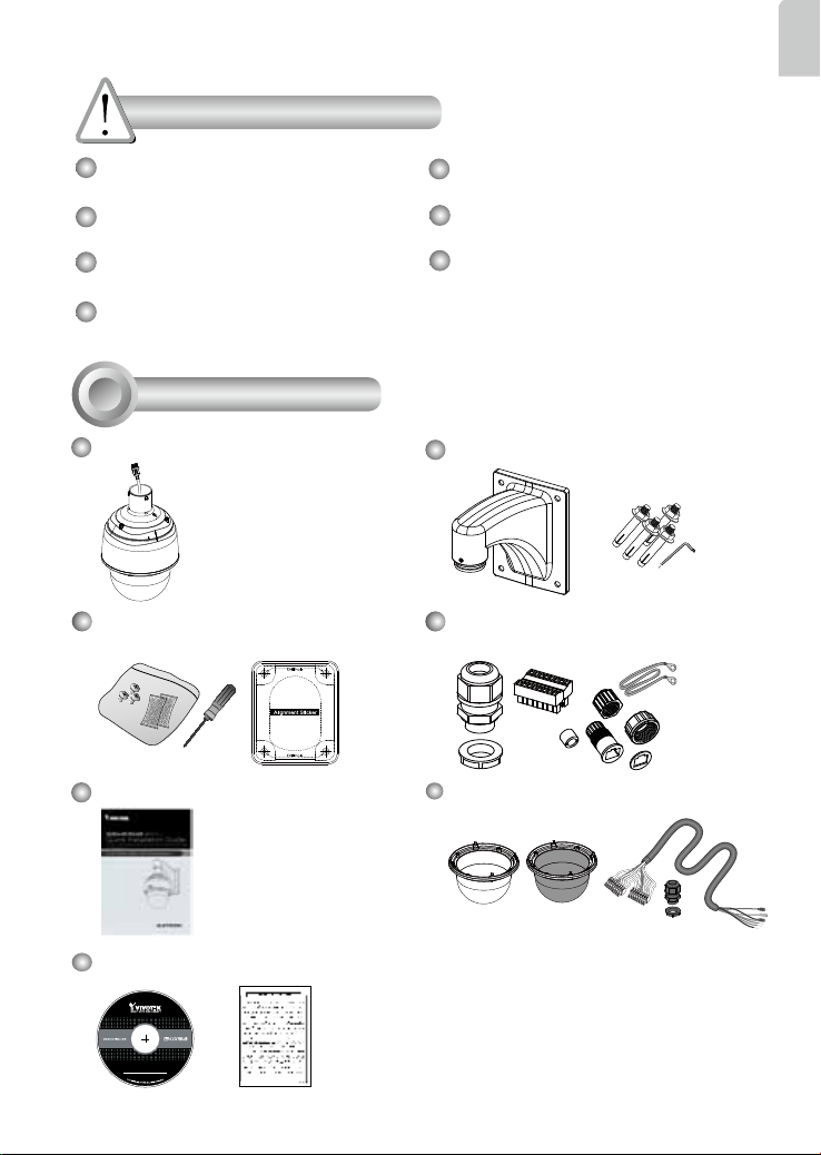
Package Contents
SD83x4E/83x6E
Screws / Alignment Sticker / T25
Stardriver / Desiccant Bags
Wall Mount Bracket / Screws
Waterproof Connectors / Terminal Blocks /
Ethernet Cable / Ground Wire
Quick Installation Guide PC/ABS / Smoked Dome Cover / IO Cable
(Separately Purchased)
Software CD / Warranty Card
EN-1
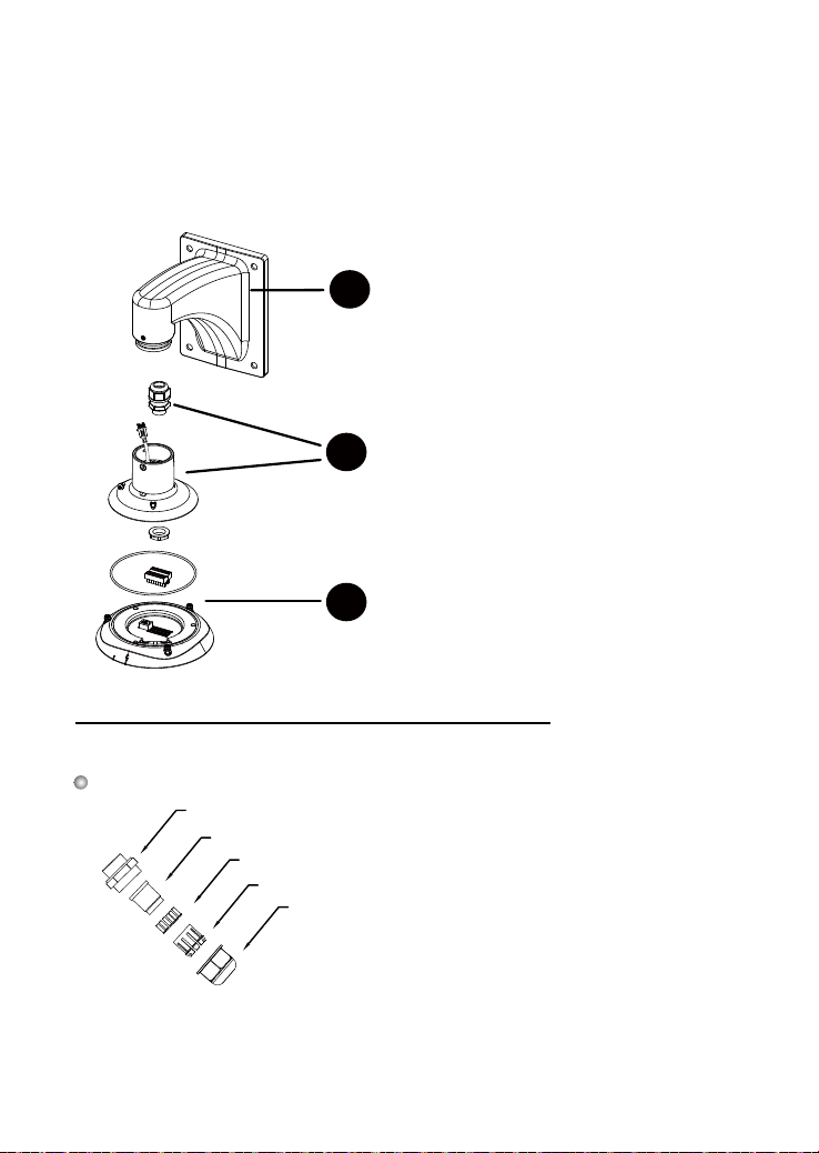
2
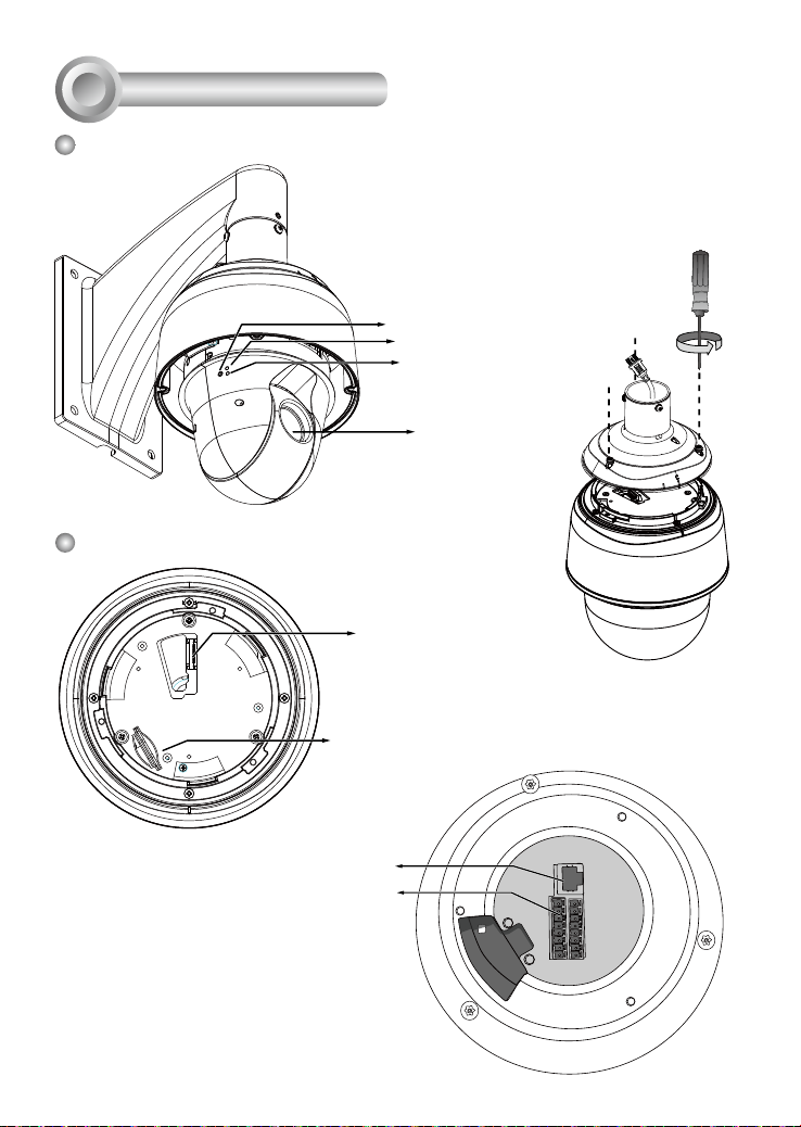
Physical Description
Outer View
Inner View
This drawing shows a camera with its dome
cover removed.
Reset Button
Network LED
Status LED
Lens
The SD card slot is accessed
by removing the top section
using the T25 stardriver.
Camera Body
Board-to-board
Connector
SD/SDHC/SDXC Card Slot
Ethernet 10/100
RJ45 Plug
General I/O
Terminal Block
EN-2
Reserved
RS485+
AC24V
AC24V
MIC IN
RS485-
Interface Section
Ethernet
DI GND
DI4
DI3
DI2
DI1
DO2
DO1
DO+(12V)
3
Hardware Installation
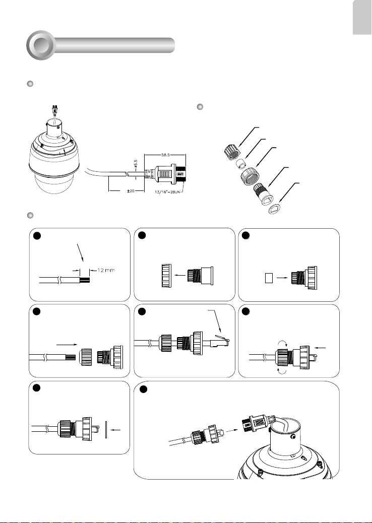
3-1. Connecting RJ45 Ethernet Cable
RJ45 Cable Dimension (unit: mm)
Use CAT5e cables only.
100
Assembling Steps
Prepare an Ethernet cable
1
and strip part of the sheath.
Insert the housing into the
2
screw nut.
Components of the Waterproof
Connector
Sealing Nut (A)
Seal (B)
Screw Nut (C)
Housing (D)
Insert the seal into the housing.
3
English
Gasket (E)
Recommended cable gauge: O.D.
5.5~7
Insert the stripped Ethernet
4
cable through the sealing
nut and the housing.
(A)
7
Attach the gasket to the front
of the housing.
(E)
(C)
Clamp the cable with
5
an RJ45 plug.
Connect the Ethernet cable to the RJ45 cable and secure the
8
connectors tightly.
(D)
(B)
Push the RJ45 plug into the
6
housing, then secure the
sealing nut tightly.
EN-3
3-2. Connecting Power and I/O Wires
If you need to connect I/O wires and 24V power, disassemble the top section of the
camera. It is highly recommended to complete the following before you can mount
the speed dome camera at the installation site:
Skip this section and move to Section 3-3 if you connect the Ethernet cable only.
Connect with the mount bracket
1-3
Cabling through the dome cap and waterproof
1-1
connectors
Plan the wire length and complete cabling to
1-2
the Interface Section
3-2-1. Cabling through the Waterproof Connectors
Components of the Waterproof Connector
Screw Nut (A)
Seal (B)
Seals (C)
Housing (D)
Sealing Nut (E)
EN-4
Wire range: 13~16AWG (1.2~1.8mm)
•
A socket wrench for the M20 hex nut is
•
required.
 Loading...