

Vivotek SD83x2E, SD83x1E, SD83x3E User Manual
IP Surveillance
SD83x1E/83x2E/83x3E
Exceptional 60fps WDR Pro PoE Plus
Rev. 1.0

VIVOTEK
2 - User's Manual
Table of Contents
Overview.......................................................................................................................................................4
Read Before Use .....................................................................................................................................5
Package Contents ................................................................................................................................... 5
Physical Description ................................................................................................................................ 6
Installation ....................................................................................................................................................8
Hardware Installation ...............................................................................................................................8
Network Deployment ............................................................................................................................. 10
Software Installation .............................................................................................................................. 12
Ready to Use .........................................................................................................................................13
Accessing the Network Camera .................................................................................................................14
Using Web Browsers .............................................................................................................................14
Using RTSP Players ..............................................................................................................................17
Using 3GPP-compatible Mobile Devices ...............................................................................................18
Using VIVOTEK Recording Software .................................................................................................... 19
Main Page ..................................................................................................................................................20
Mouse Control ....................................................................................................................................... 25
Client Settings ............................................................................................................................................26
Conguration ..............................................................................................................................................28
System > General settings ....................................................................................................................29
System > Homepage layout .................................................................................................................31
System > Logs ......................................................................................................................................34
System > Parameters ...........................................................................................................................35
System > Maintenance ..........................................................................................................................36
Security > User Account ........................................................................................................................40
Security > HTTPS (Hypertext Transfer Protocol over SSL) ........................................................41
Security > Access List .........................................................................................................................46
Network > General settings ...................................................................................................................51
Network > Streaming protocols ...........................................................................................................58
Network > SNMP (Simple Network Management Protocol)
.............................................67
Media > Image ....................................................................................................................................68
Media > Video ......................................................................................................................................78
Media > Audio........................................................................................................................................ 81
PTZ > PTZ settings ..............................................................................................................................82
Event > Event settings ..........................................................................................................................84
Applications > Motion detection.............................................................................................................97
Applications > DI and DO ..................................................................................................................100
Applications > Audio detection ..........................................................................................................101
Recording > Recording settings .........................................................................................................103
Local storage > SD card management ................................................................................................108
Local storage > Content management ................................................................................................109
Appendix .................................................................................................................................................. 111

VIVOTEK
User's Manual - 3
URL Commands for the Network Camera ...........................................................................................................111
Technical Specications ..................................................................................................................................... 192
Technology License Notice ................................................................................................................................. 193
Electromagnetic Compatibility (EMC) ................................................................................................................. 194

VIVOTEK
4 - User's Manual
Overview
VIVOTEK SD83x1E/2E/3E is a series of high performance day/night speed dome network
cameras suitable for professional outdoor surveillance applications. The IP66-rated housing
protects the camera body against rain and dust and the wide temperature range ensures
operation under extreme weather conditions. It is especially suitable for monitoring wide open
indoor/outdoor spaces such as airports, highways, and parking lots where high-level reliability
and precision are always required.
The SD83x1E/2E/3E support high-performance H.264/MPEG-4/MJPEG compression
technology and offer extra smooth video quality up to 60 fps @ D1 Resolution. Boasting WDR
Pro technology, the SD83x1E/2E/3E can also cope with challenging lighting conditions and
generate image quality similar to the capabilities of the human eye. With sophisticated pan/tilt
mechanism, the camera provides fast, precise movement with continuous 360-degree pan and
90-degree tilt. Users can easily control the lens position via a mouse or a joystick to track the
object of interest and set up to 128 preset positions for patrolling.
As with all VIVOTEK true day/night cameras, the SD83x1E/2E/3E feature removable IR-cut lter,
maintaining clear images 24 hours a day. The built-in SD/SDHC card slot offers a convenient
and portable storage option to prevent data loss in case of network disconnection. With other
advanced features such as audio detection, 802.3at compliant PoE Plus and 60 fps high quality
video, the SD83x1E/2E/3E are the best choices for the most demanding outdoor surveillance
applications.

VIVOTEK
User's Manual - 5
Read Before Use
The use of surveillance devices may be prohibited by law in your country. The Network Camera is not
only a high-performance web-ready camera but can also be part of a exible surveillance system. It is
the user’s responsibility to ensure that the operation of such devices is legal before installing this unit for
its intended use.
It is important to rst verify that all contents received are complete according to the Package Contents
listed below. Take note of the warnings in the Quick Installation Guide before the Network Camera is
installed; then carefully read and follow the instructions in the Installation chapter to avoid damage due to
faulty assembly and installation. This also ensures the product is used properly as intended.
The Network Camera is a network device and its use should be straightforward for those who have basic
networking knowledge. It is designed for various applications including video sharing, general security/
surveillance, etc. The Configuration chapter suggests ways to best utilize the Network Camera and
ensure proper operations. For creative and professional developers, the URL Commands of the Network
Camera section serves as a helpful reference to customizing existing homepages or integrating with the
current web server.
Package Contents
■ SD83xxE
■ Black Cover / Clear Dome Cover
■ Power Adapter (optional)
■ Wall Mount Bracket
■ O-ring and Screws / Alignment Sticker
■ Metal Ring / Moisture Absorber
■ RJ45 Female/Female Coupler
■ Quick Installation Guide
■ Warranty Card
■ Software CD
VIVOTEK
6 - User's Manual
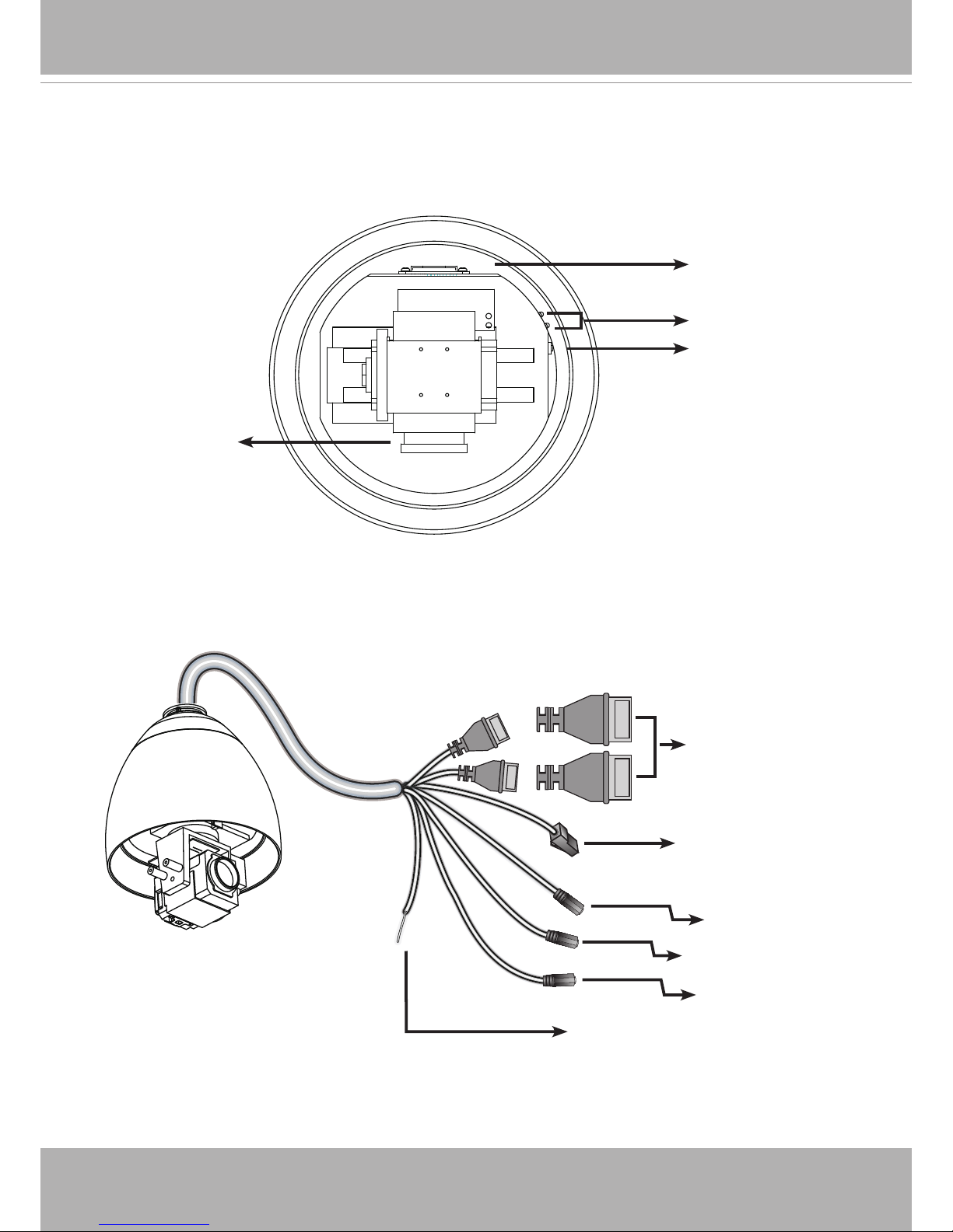
Physical Description
Reset Button
Lens
Status LEDs
SD Card Slot
GND
DO2-
DO1-
DO+
GND
D13
D12
D11
GND
DO2DO1DO+
GND
D13
D12
D11
Ethernet 10/100 RJ45
Plug
Audio Out (green)
Microphone In (pink)
Power Cord Socket
(black)
General I/O Terminal
Block
Ground
VIVOTEK
User's Manual - 7
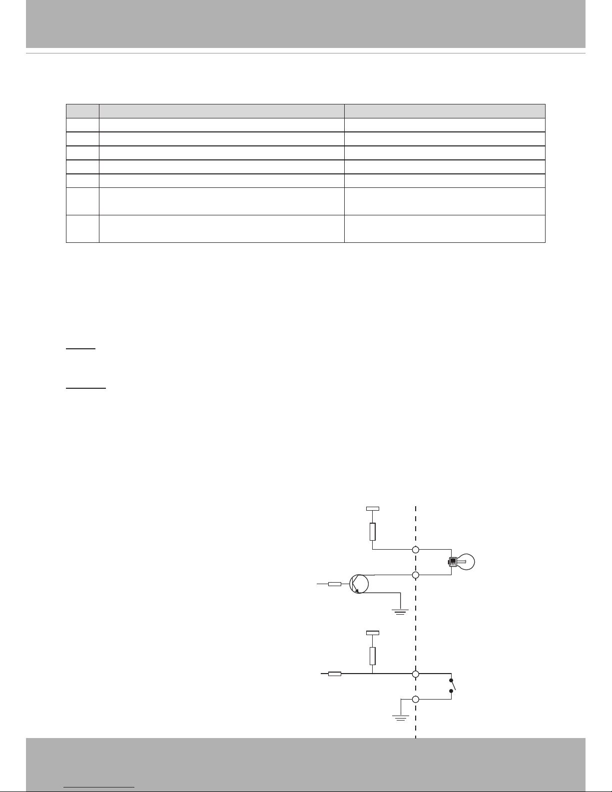
Status LED
Item LED status Description
1 Steady red Power on and system booting
Red LED off Power off
2 Steady red & Green blinking every 1 sec. Network normal (heartbeat)
Steady red & Green LED off Network failed
3 Steady red & Green LED blilnking every 2 sec. Audio mute (heartbeat)
4 Red blinking every 0.15 sec. & Green blinking
every 1 sec.
Upgrading rmware
5 Red blinking every 0.15 sec. & Green blinking
every 0.15 sec.
Restoring default
Hardware Reset
The reset button is used to reset the system or restore the factory default settings. Sometimes
resetting the system can return the camera to normal operation. If the system problems remain
after reset, restore the factory settings and install again.
Reset: Press and release the recessed reset button with a straightened paper clip. Wait for the
Network Camera to reboot.
Restore: Press and hold the recessed reset button for a while to restore. Note that almost all
previous conguration changes will be restored to factory default.
SD/SDHC Card Capacity
This network camera is compliant with SD/SDHC 32GB and other preceding standard SD cards.
DI/DO Diagram
Please refer to the following illustration
for the connection method.
12V
+12V
Digital output
PIN 1
Power+12V
PIN 2
Digital input
PIN 3
Ground
PIN 4
VIVOTEK
8 - User's Manual
Installation
Hardware Installation
1
2
3
5
6
7
8
9
10
Silica gel
Silica gel
4
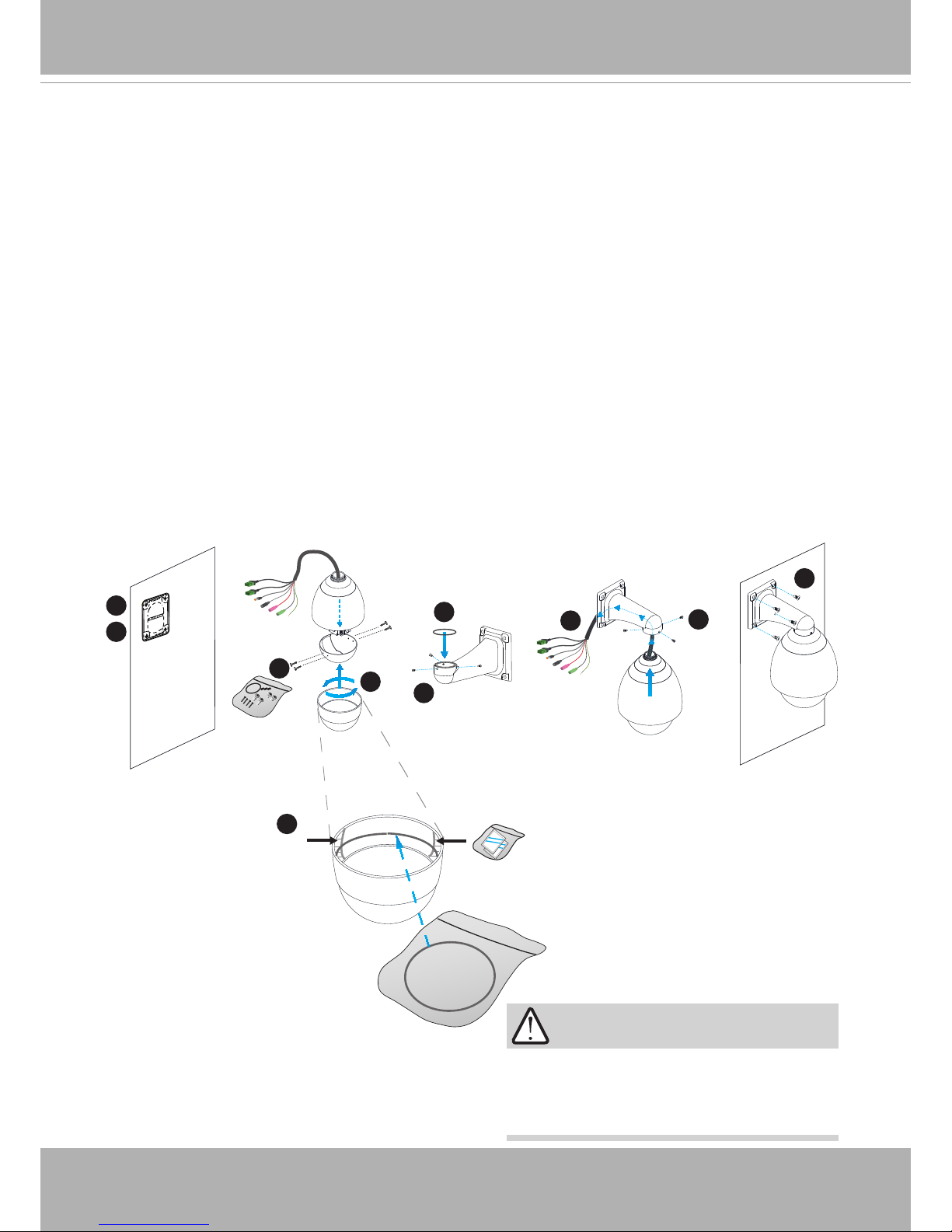
Mounting the Network Camera
1. Attach the alignment sticker to the wall.
2. Drill four pilot holes into the wall.
3. Attach the black cover to the Network Camera using the supplied four black screws.
4. Stick the supplied two pieces of moisture absorber symmetrically to the inner side of the
dome cover. Then place the metal ring into the dome cover to x the moisture absorber.
5. Fix the dome cover to the Network Camera and secure it by rotating it clockwise.
6. Loosen the three screws on the front opening of the wall mount bracket.
7. Place the O-ring on the front opening of the wall mount bracket.
8. Feed the cables through the front opening of the wall mount bracket and pull them from wall
outlet.
9. Attach the Network Camera to the wall mount bracket by tightening the three screws you
previously removed.
10. Fasten the wall mount bracket to the pre-drilled holes on the wall.
IMPORTANT!
The supplied L-type hex wrenches
are exclusively designed to match the
camera''s screws. Keep them for future
use. Do not discard the wrenches.
VIVOTEK
User's Manual - 9
GND
DO2-
DO1-
DO+
GND
D13
D12
D11
P
O
W
E
R
C
O
L
L
I
S
IO
N
L
I
N
K
RE
CEIVE
PA
RT
ITI
O
N
1
2
3
4
5
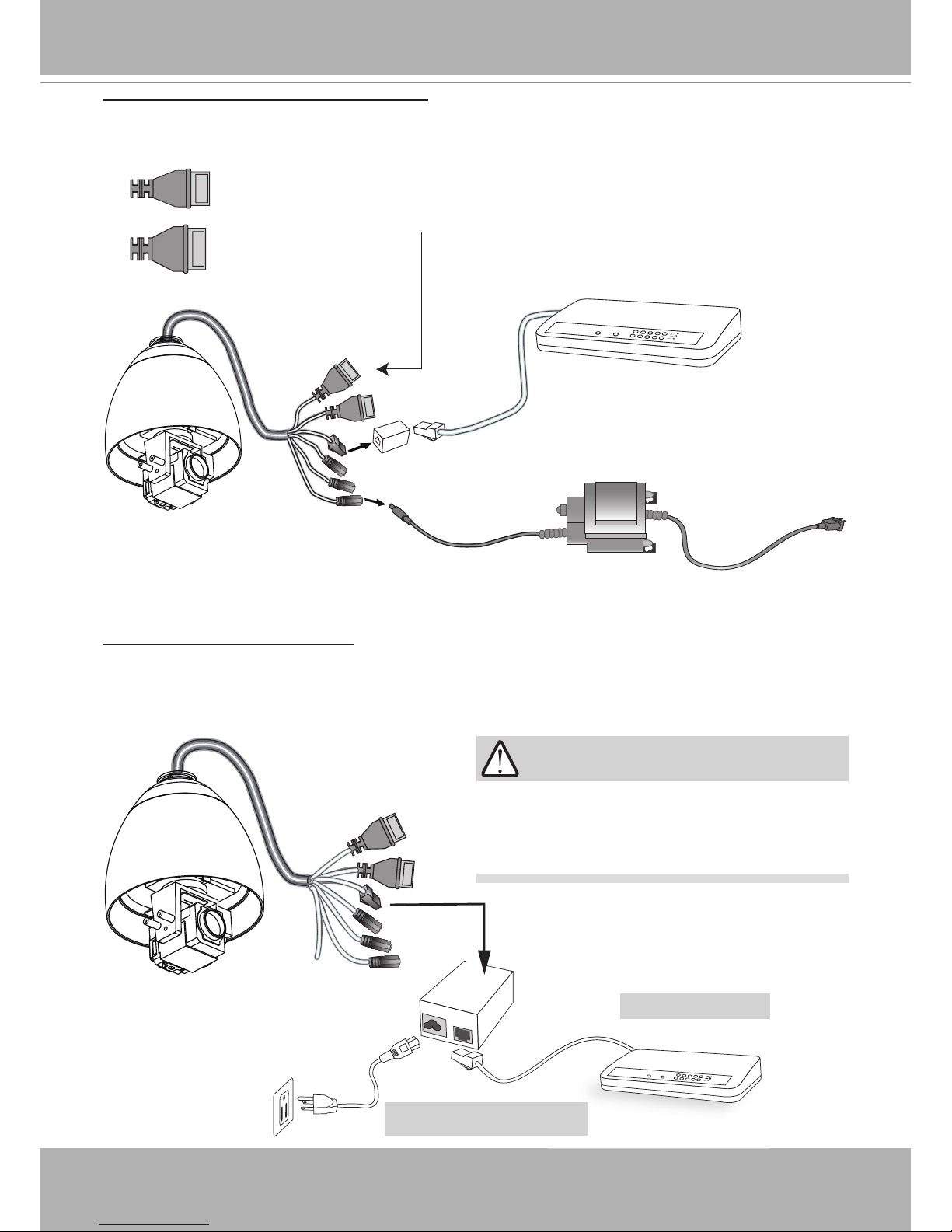
1. If you have external devices such as sensors and
alarms, connect them to the general I/O terminal
block.
2. Use the supplied RJ45 female/female coupler
to connect the Network Camera to a switch.
Use Category 5 Cross Cable when Network
Camera is directly connected to a PC.
GND
DO2DO1DO+
GND
DI3
DI2
DI1
(AC 24V 3.5A) Power Adapter
POWER
COLLISION
LINK
RECEIVE
PARTITION
1
2
3
4
5
GND
DO2-
DO1-
DO+
GND
D13
D12
D11
When using a non-PoE switch
Use a PoE Plus power injector to connect between the Network Camera and a nonPoE switch.
Non-PoE Switch
PoE Plus Power Injector
3. Connect the power cable from the
Network Camera to a power outlet.
Power over Ethernet (PoE)
General Connection (without PoE)
GND: Ground
DO2: Digital Output 2
DO1: Digital Output 1
DO+: Digital Outupt (DC12V)
GND: Ground
DI3: Digital Input 3
DI2: Digital Input 2
DI1: Digital Input 1
1. The camera is only to be connected to PoE
networks without routing to outside plants.
2. For PoE connection, use only UL listed I.T.E. with
PoE output.
IMPORTANT!
VIVOTEK
10 - User's Manual
Network Deployment
Setting up the Network Camera over the Internet
There are several ways to set up the Network Camera over the Internet. The rst way is to set
up the Network Camera behind a router. The second way is to utilize a static IP. The third way is
to use PPPoE.
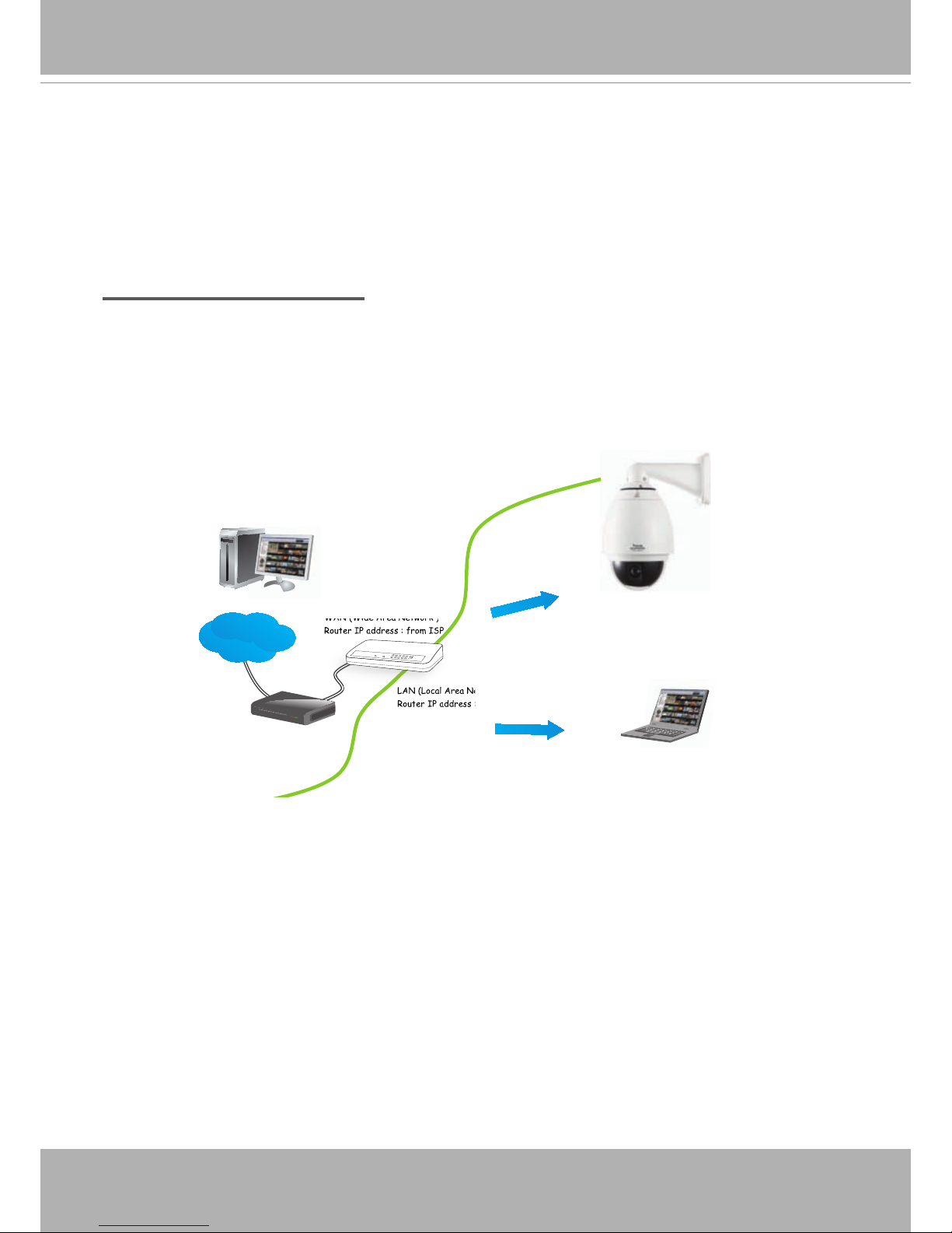
Internet connection via a router
Before setting up the Network Camera over the Internet, make sure you have a router and follow
the steps below.
1. Connect your Network Camera behind a router, the Internet environment is illustrated below.
Regarding how to obtain your IP address, please refer to Software Installation on page 12 for
details.
2. In this case, if the Local Area Network (LAN) IP address of your Network Camera is
192.168.0.3, please forward the following ports for the Network Camera on the router.
■ Secondary HTTP port
■ RTSP port
■ RTP port for audio
■ RTCP port for audio
■ RTP port for video
■ RTCP port for video
If you have changed the port numbers on the Network page, please open the ports accordingly
on your router. For information on how to forward ports on the router, please refer to your
router’s user’s manual.
3. Find out the public IP address of your router provided by your ISP (Internet Service Provider).
Use the public IP and the secondary HTTP port to access the Network Camera from the
Internet. Please refer to Network Type on page 51 for details.
IP address : 192.168.0.3
Subnet mask : 255.255.255.0
Default router : 192.168.0.1
IP address : 192.168.0.2
Subnet mask : 255.255.255.0
Default router : 192.168.0.1
LAN (Local Area Network)
Router IP address : 192.168.0.1
WAN (Wide Area Network )
Router IP address : from ISP
Cable or DSL Modem
L
A
N (
Local Area Network)
R
o
u
t
e
r
I
P
a
d
dre
s
s
W
A
N (Wide Area Network )
R
o
u
t
e
r
I
P
a
d
dre
s
s
f
r
o
m
I
S
P
POWER
COLLISION
LINK
RECEIVE
PARTITION
1
2
3
4
5
Internet

VIVOTEK
User's Manual - 11
Internet connection with static IP
Choose this connection type if you are required to use a static IP for the Network Camera.
Please refer to LAN on page 51 for details.
Internet connection via PPPoE (Point-to-Point over Ethernet)
Choose this connection type if you are connected to the Internet via a DSL Line. Please refer to
PPPoE on page 52 for details.
VIVOTEK
12 - User's Manual
Software Installation
Installation Wizard 2 (IW2), free-bundled software included on the product CD, helps you set up
your Network Camera on the LAN.
1. Install IW2 under the Software Utility directory from the software CD.
Double click the IW2 shortcut on your desktop to launch the program.
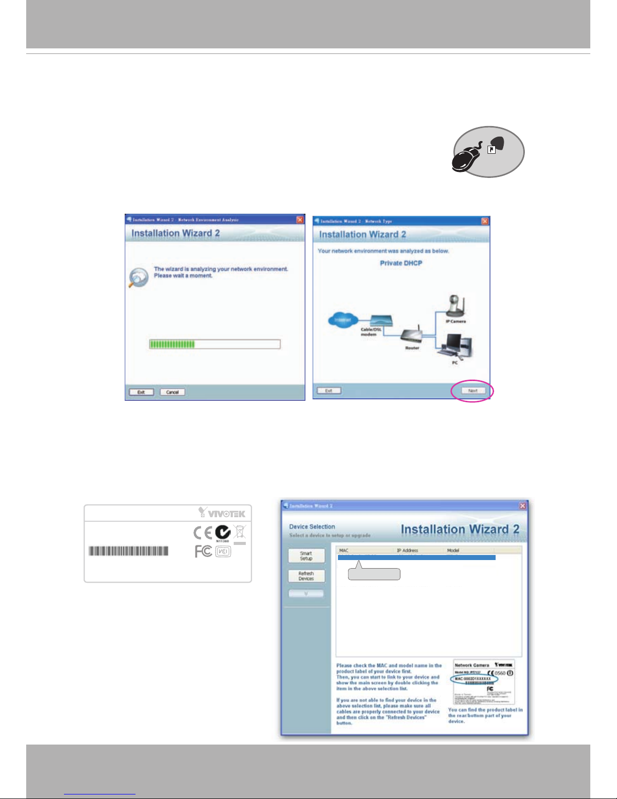
2. The program will conduct an analysis of your network environment.
After your network environment is analyzed, please click Next to continue the program.
3. The program will search for all VIVOTEK network devices on the same LAN.
4. After a brief search, the main installer window will prompt. Double-click on the MAC and
model name which matches the product label on your device to connect to the Network
Camera via a web browser.
0002D1730202
00-02-D1-73-02-02 192.168.5.151 IP8362
Installation
Wizard 2
IW
2
Network Camera
Model No: SD8313E
Made in Taiwan
This device complies with part 15 of the FCC rules. Operation is subject to the following two conditions:
(1)This device may not cause harmful interference, and
(2) this device must accept any interference received, including interference that may cause undesired operation.
Pat. 6,930,709
MAC:0002D1730202
R o H S
VIVOTEK
User's Manual - 13
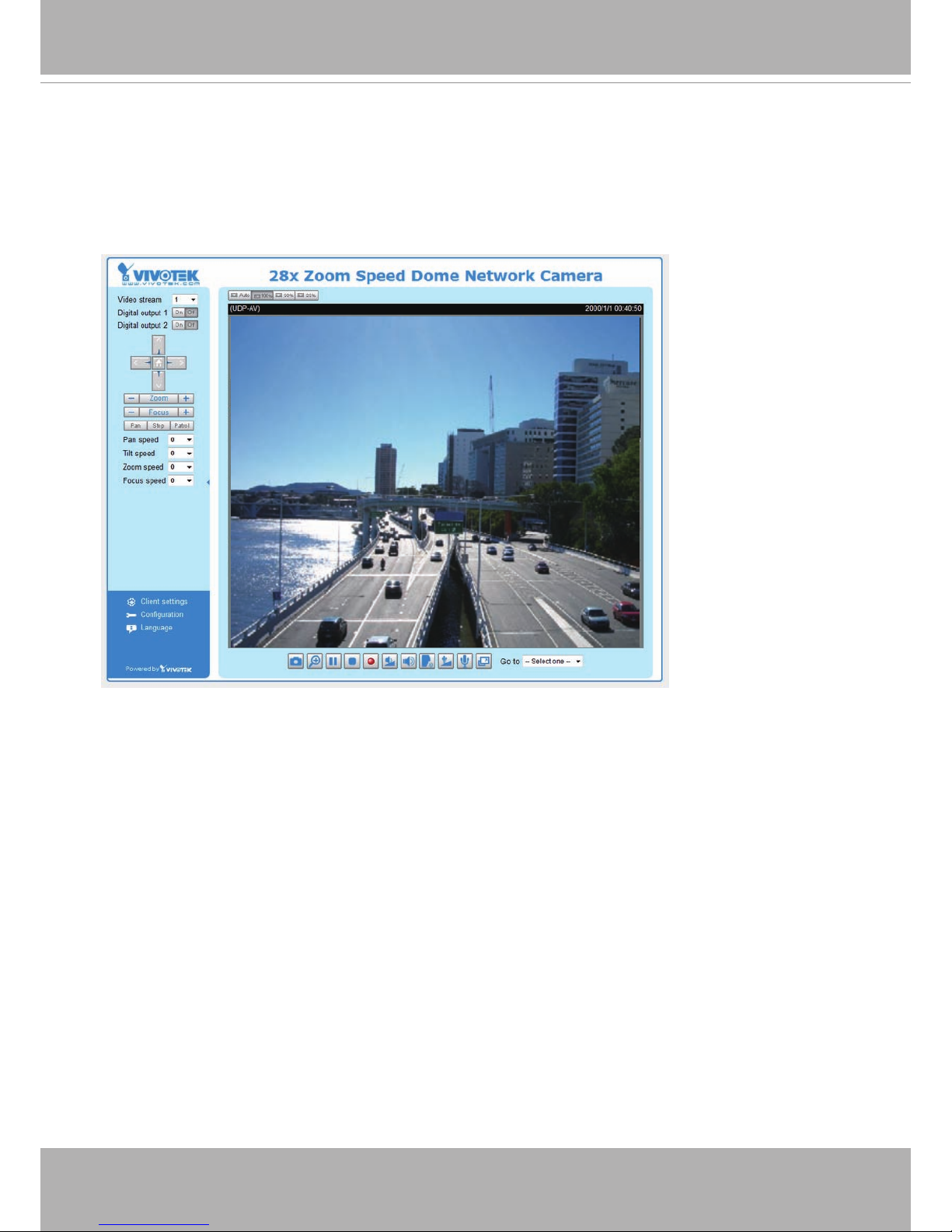
Ready to Use
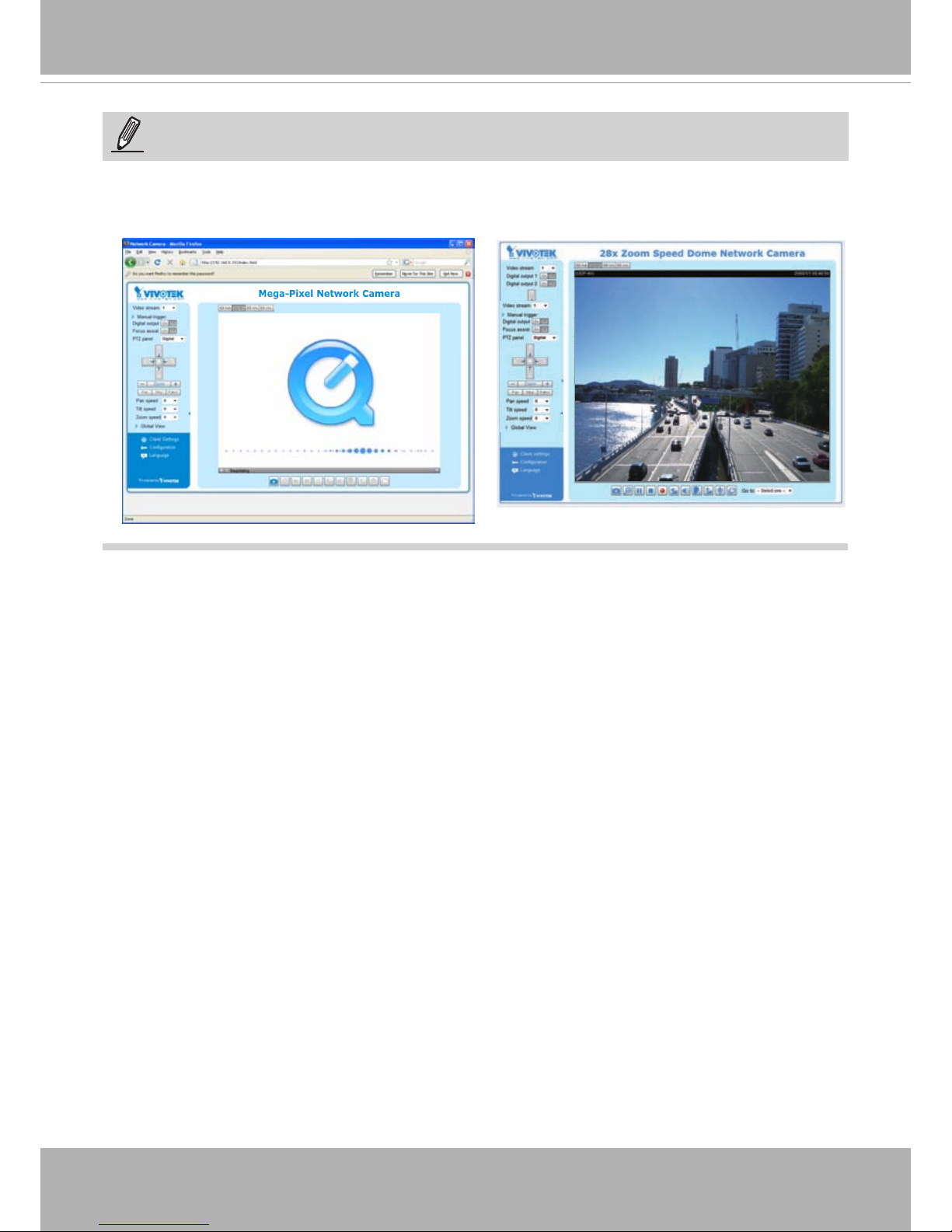
1. A browser session with the Network Camera should prompt as shown below.
2. You should be able to see live video from your camera. You may also install the 32-channel
recording software from the software CD in a deployment consisting of multiple cameras. For
its installation details, please refer to its related documents.
VIVOTEK
14 - User's Manual
Accessing the Network Camera
This chapter explains how to access the Network Camera through web browsers, RTSP players,
3GPP-compatible mobile devices, and VIVOTEK recording software.
Using Web Browsers
Use Installation Wizard 2 (IW2) to access to the Network Cameras on the LAN.
If your network environment is not a LAN, follow these steps to access the Netwotk Camera:
1. Launch your web browser (e.g., Microsoft
®
Internet Explorer, Mozilla Firefox, or Netscape).
2. Enter the IP address of the Network Camera in the address eld. (A temporary IP will be
generated for the camera. Find it in your Network Neighborhood). Press Enter.
3. Live video will display in your web browser.
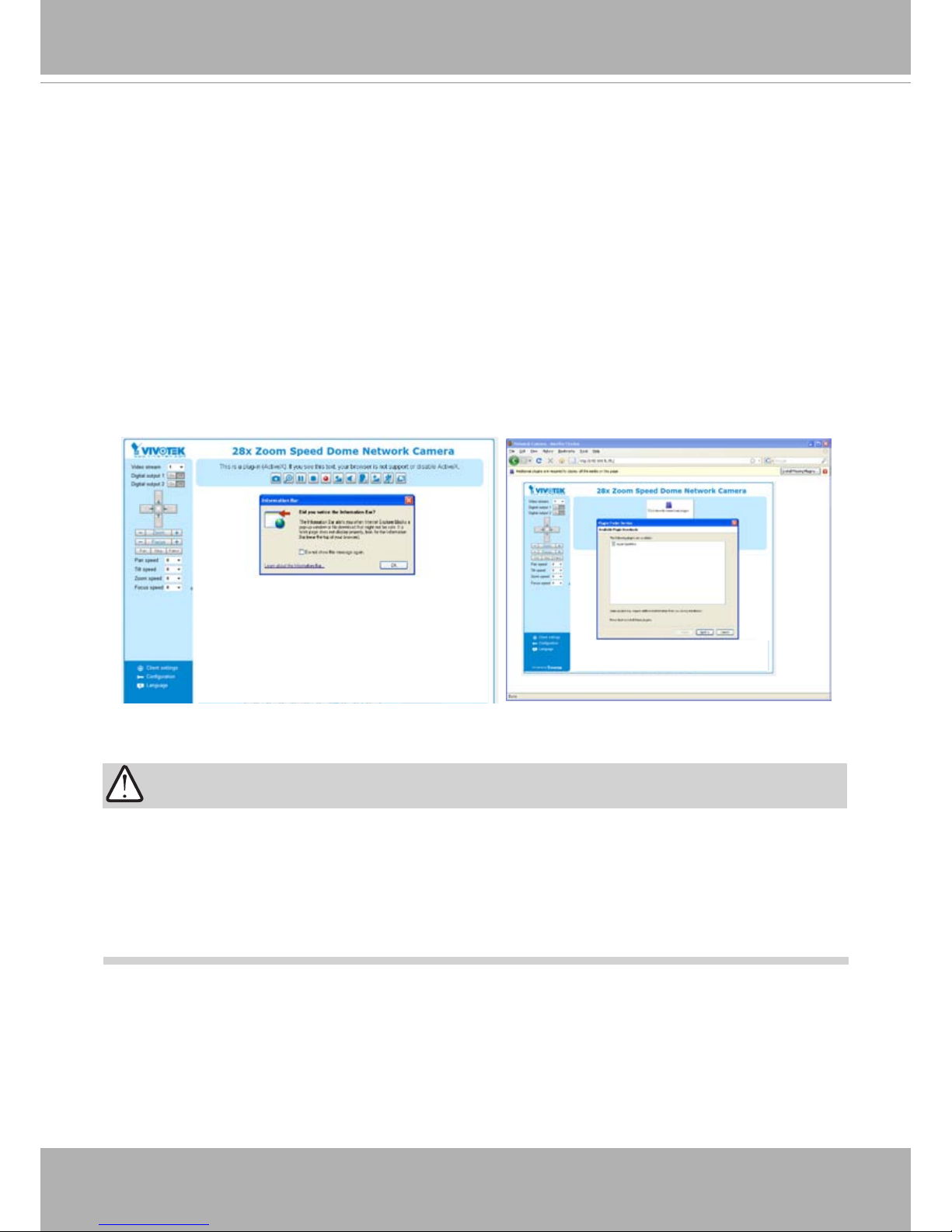
4. If it is the rst time installing the VIVOTEK network camera, an information bar will pop up as
shown below. Follow the instructions to install the required plug-in on your computer.
IMPORTANT!
•
Currently the Network Camera utilizes 32-bit ActiveX plugin. You CAN NOT open a
management/view session with the camera using a 64-bit IE browser.
•
If you encounter this problem, try execute the Iexplore.exe program from C:\
Windows\SysWOW64. A 32-bit version of IE browser will be installed.
•
On Windows 7, the 32-bit explorer browser can be accessed from here: C:\Program
Files (x86)\Internet Explorer\iexplore.exe
VIVOTEK
User's Manual - 15
NOTE:
For Mozilla Firefox or Netscape users, your browser will use Quick Time to stream live
video. If you do not have Quick Time on your computer, please download Quick Time
from Apple Inc's website, and then launch your web browser.
VIVOTEK
16 - User's Manual
► By default, the Network Camera is not password-protected. To prevent unauthorized
access, it is highly recommended to set a password for the Network Camera.
For more information about how to enable password protection, please refer to Security
on page 40.
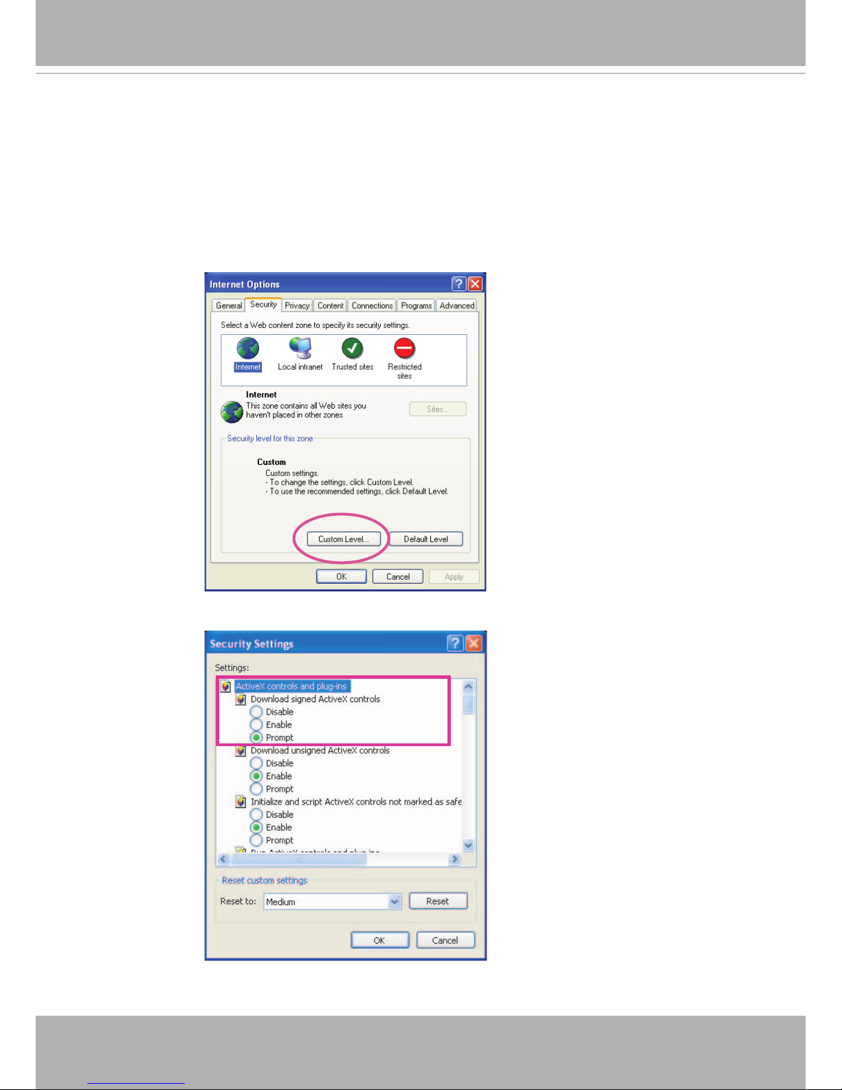
► If you see a dialog box indicating that your security settings prohibit running ActiveX
®
Controls, please enable the ActiveX
®
Controls for your browser.
1. Choose Tools > Internet Options > Security > Custom Level.
2. Look for Download signed ActiveX
®
controls; select Enable or Prompt. Click OK.
3. Refresh your web browser, then install the ActiveX
®
control. Follow the instructions to
complete installation.
VIVOTEK
User's Manual - 17
Using RTSP Players
To view the H.264/MPEG-4 streaming media using RTSP players, you can use one of the
following players that support RTSP streaming.
Quick Time Player
Real Player
VLC media player
mpegable Player
pvPlayer
As most ISPs and players only allow RTSP streaming through port number 554, please set the
RTSP port to 554. For more information, please refer to RTSP Streaming on page 59.
For example:
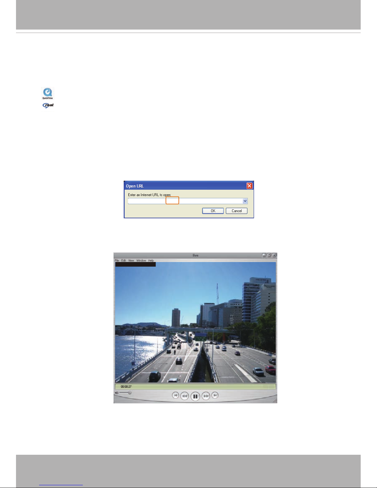
4. The live video will be displayed in your player.
For more information on how to configure the RTSP access name, please refer to RTSP
Streaming on page 59 for details.
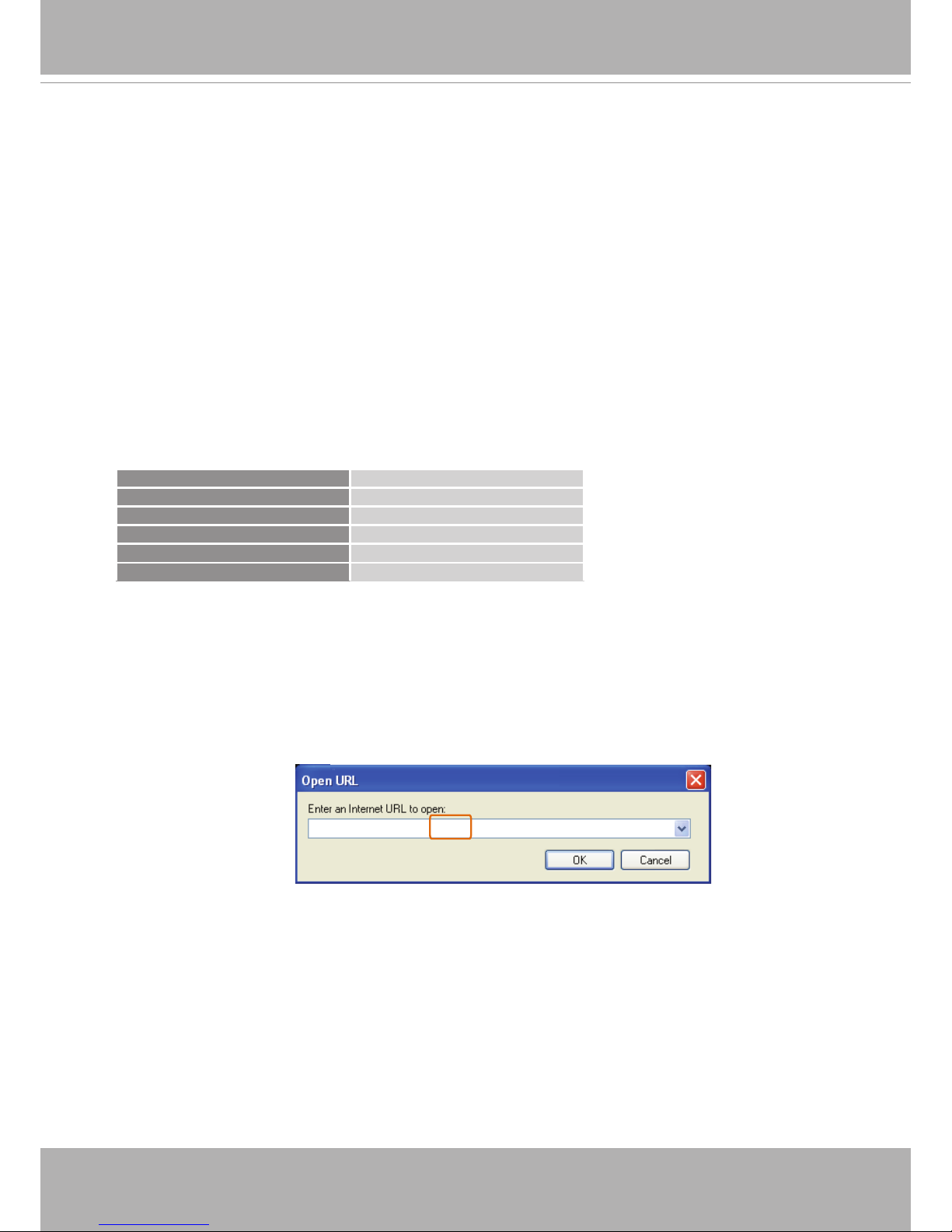
1. Launch the RTSP player.
2. Choose File > Open URL. An URL dialog box will pop up.
3. The address format is rtsp://<ip address>:<rtsp port>/<RTSP streaming access name for
stream1 or stream2>
rtsp://192.168.5.151:554/live.sdp
Video 16:38:01 2011/03/25
VIVOTEK
18 - User's Manual
Using 3GPP-compatible Mobile Devices
To view the streaming media through 3GPP-compatible mobile devices, make sure the Network
Camera can be accessed over the Internet. For more information on how to set up the Network
Camera over the Internet, please refer to Setup the Network Camera over the Internet on page
10.
To utilize this feature, please check the following settings on your Network Camera:
1. Because most players on 3GPP mobile phones do not support RTSP authentication, make
sure the authentication mode of RTSP streaming is set to disable.
For more information, please refer to RTSP Streaming on page 59.
2. As the bandwidth on 3G networks is limited, you will not be able to use a large video size.
Please set the video and audio streaming parameters as listed below.
For more information, please refer to Stream settings on page 78.
Video Mode MPEG-4
Frame size 176 x 144
Maximum frame rate 5 fps
Intra frame period 1S
Video quality (Constant bit rate) 40kbps
Audio type (GSM-AMR) 12.2kbps
3. As most ISPs and players only allow RTSP streaming through port number 554, please set
the RTSP port to 554. For more information, please refer to RTSP Streaming on page 59.
4. Launch the player on the 3GPP-compatible mobile devices (ex. Real Player).
5. Type the following URL commands into the player.
The address format is rtsp://<public ip address of your camera>:<rtsp port>/<RTSP streaming
access name for stream 3>.
For example:
rtsp://192.168.5.151:554/live.sdp
VIVOTEK
User's Manual - 19
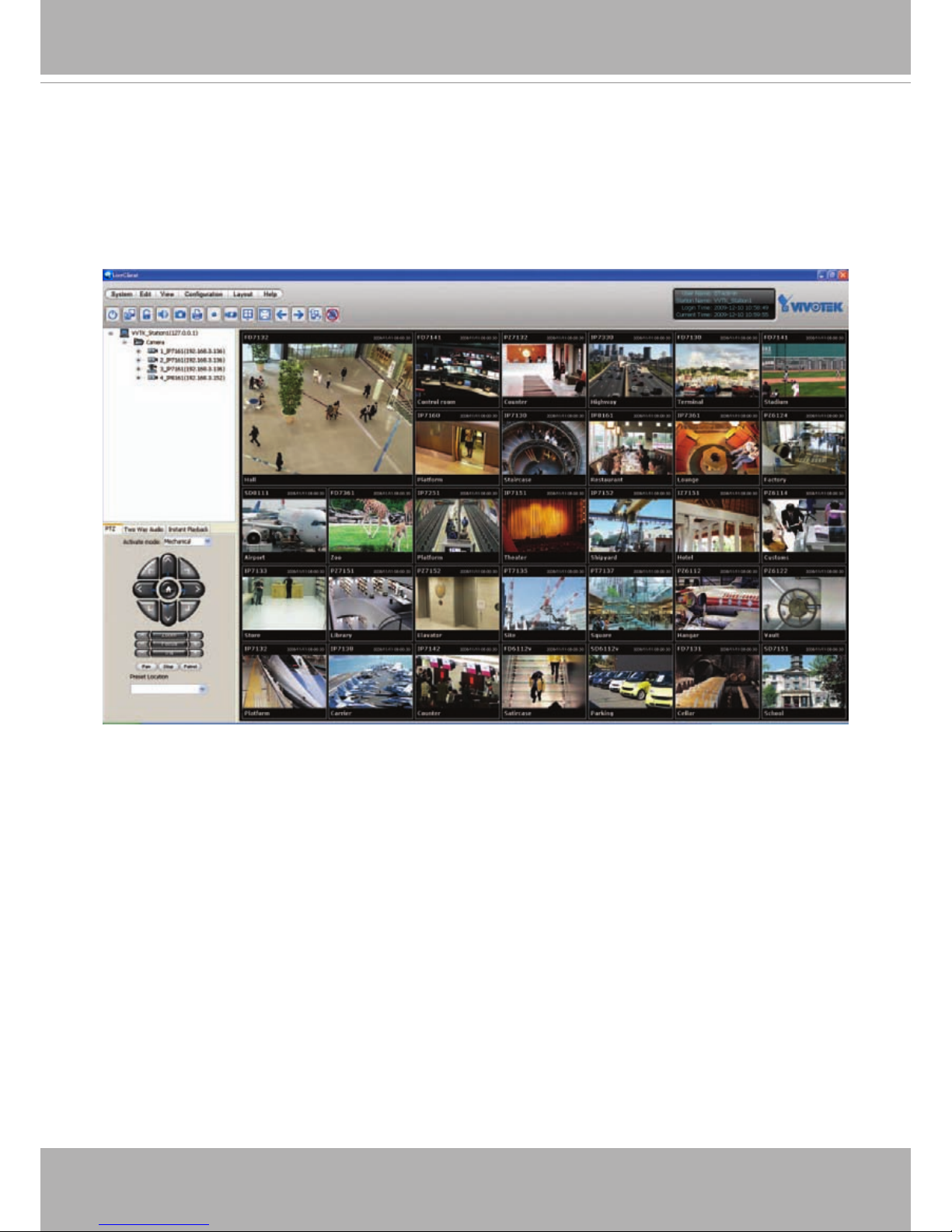
Using VIVOTEK Recording Software
The product software CD also contains recording software, allowing simultaneous monitoring
and video recording for multiple Network Cameras. Please install the recording software; then
launch the program to add the Network Camera to the Channel list. For detailed information
about how to use the recording software, please refer to the user’s manual of the software or
download it from http://www.vivotek.com.
VIVOTEK
20 - User's Manual
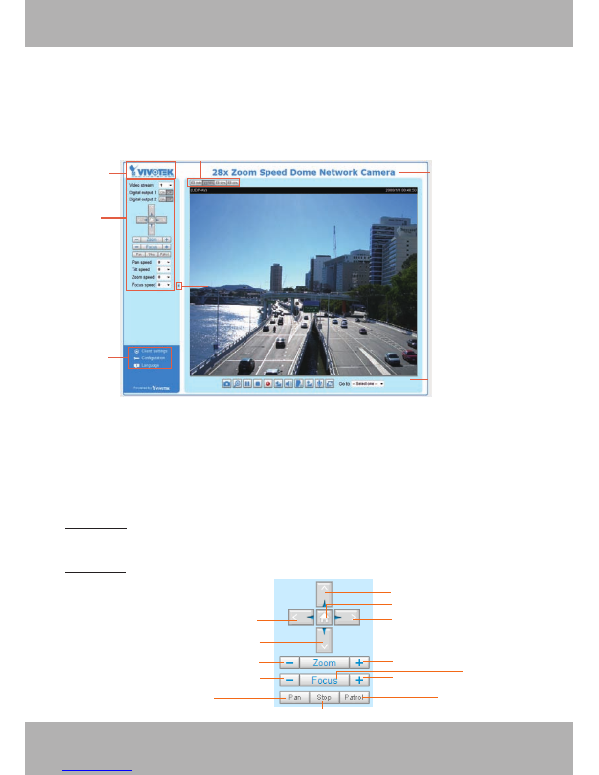
Main Page
This chapter explains the layout of the main page. It is composed of the following sections:
VIVOTEK INC. Logo, Host Name, Camera Control Area, Configuration Area, and Live Video
Window.
VIVOTEK INC. Logo
Click this logo to visit the VIVOTEK website.
Host Name
The host name can be customized to t your needs. For more information, please refer to System on page 29.
Camera Control Area
Video Stream: This Network Camera supports multiple streams (stream 1 ~ 4) simultaneously. You can
select any of them for live viewing. For more information about multiple streams, please refer to page 78
for detailed information.
Digital Output: Click to turn the digital output device on or off.
PTZ Control Panel:
Live View Window
Host Name
VIVOTEK INC.
Logo
Camera Control
Area
Configuration
Area
Resize Buttons
Hide Button
Left
Down
Zoom Out
Focus Near
Start to Auto Patrol
Start to Auto Pan
Stop Auto Panning/patrolling
Return to Home Position
Right
Up
Zoom In
Focus Far
Auto Focus
VIVOTEK
User's Manual - 21
You can also use a joystick or simply mouse clicks on a live view window to move to an area of interest.
Pan: Click this button to start the auto pan (360° continuous rotation).
Stop: Click this button to stop the Auto Pan and Auto Patrol functions.
Patrol: Once the Administrator has determined the list of preset positions, click this button to command
the camera to patrol among those positions on the Patrol List. The Network Camera will patrol
continuously. For more information, please refer to Camera Control on page 82.
Pan /Tilt /Zoom /Focus speed: Adjust the speed of Pan/ Tilt/ Zoom/ Focus:
Conguration Area
Client Settings: Click this button to access the client setting page. For more information, please refer to
Client Settings on page 26.
Conguration: Click this button to access the conguration page of the Network Camera. It is suggested
that a password be applied to the Network Camera so that only the administrator can configure the
Network Camera. For more information, please refer to Conguration on page 28.
Language: Click this button to choose a language for the user interface. Language options are available
in: English, Deutsch, Español, Français, Italiano,
日本語
, Português,
簡体中文
, and
繁體中文
. You can
also change a language on the Conguration page; please refer to page 28.
Hide Button
You can click the hide button to hide the control panel or display the control panel.
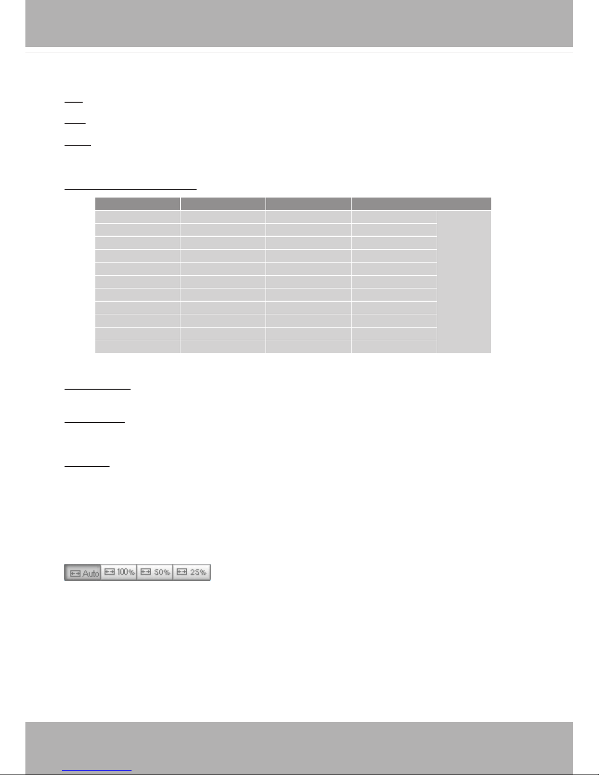
Resize Buttons
:
Click the Auto button, the video cell will resize automatically to t the current browser window.
Click 100% is to display the original homepage size.
Click 50% is to resize the homepage to 50% of its original size.
Click 25% is to resize the homepage to 25% of its original size.
Pan speed Tilt speed Zoom speed Focus speed
-5 -5 -5 -5 Slower
Faster
-4 -4 -4 -4
-3 -3 -3 -3
-2 -2 -2 -2
-1 -1 -1 -1
0 0 0 0
1 1 1 1
2 2 2 2
3 3 3 3
4 4 4 4
5 5 5 5
VIVOTEK
22 - User's Manual
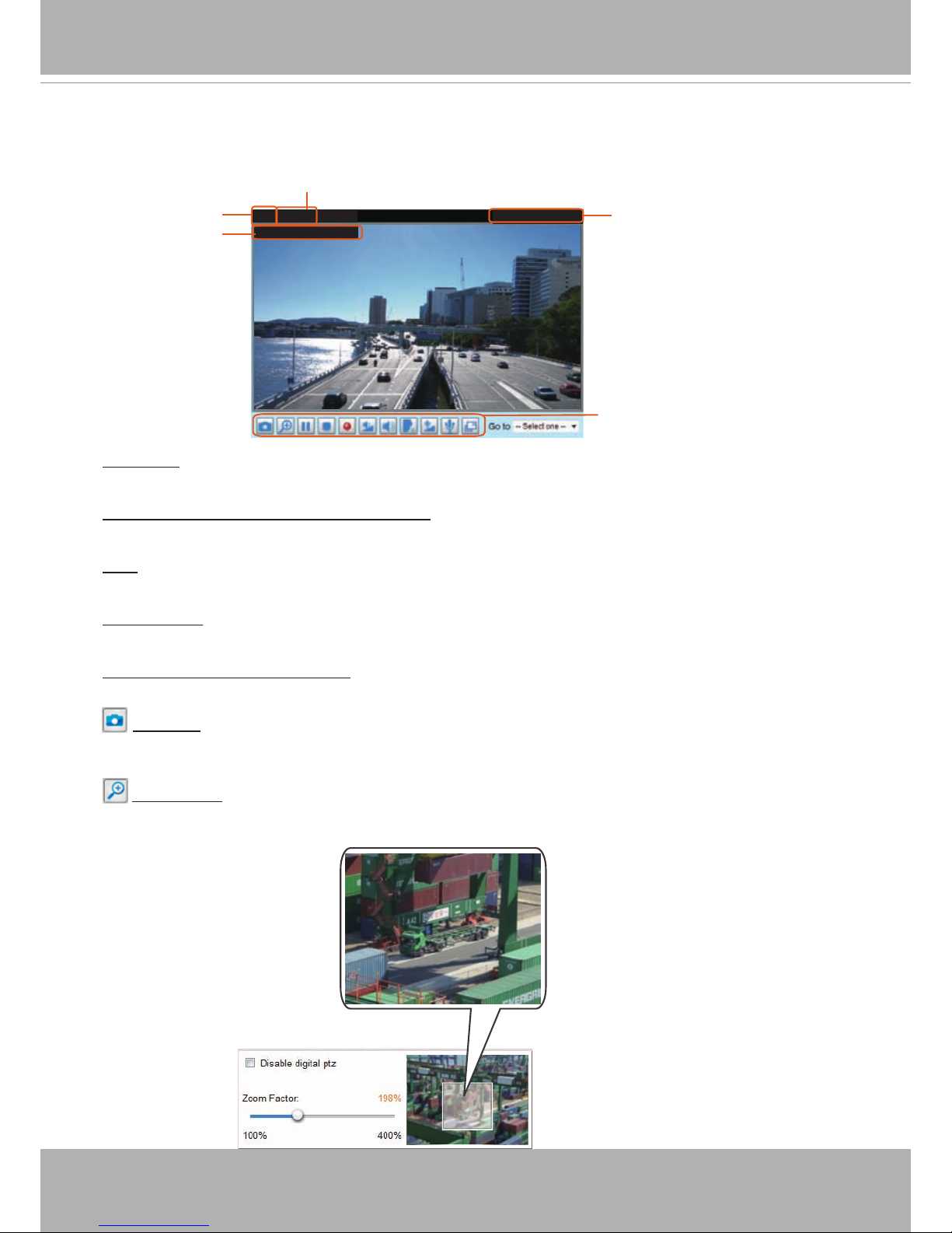
Live Video Window
■ The following window is displayed when the video mode is set to H.264 / MPEG-4:
Video Title: The video title can be congured. For more information, please refer to Video settings on
page 68.
H.264 / MPEG-4 Protocol and Media Options: The transmission protocol and media options for H.264 /
MPEG-4 video streaming. For further conguration, please refer to Client Settings on page 26.
Time: Display the current time. For further conguration, please refer to Media > Image > Genral settings
on page 68.
Title and Time: The video title and time can be stamped on the streaming video. For further conguration,
please refer to Media > Image > General settings on page 68.
Video and Audio Control Buttons: Depending on the Network Camera model and Network Camera
conguration, some buttons may not be available.
Snapshot: Click this button to capture and save still images. The captured images will be displayed
in a pop-up window. Right-click the image and choose Save Picture As to save it in JPEG (*.jpg) or BMP
(*.bmp) format.
Digital Zoom: Click and uncheck “Disable digital zoom” to enable the zoom operation. The navigation
screen indicates the part of the image being magnied. To control the zoom level, drag the slider bar. To
move to a different area you want to magnify, drag the navigation screen.
Video 17:08:56 2011/03/10
Title and Time
2011/03/10 17:08:56
Time
Video and Audio Control Buttons
Video (TPC-AV)
H.264/MPEG-4 Protocol and Media Options
Video Title
VIVOTEK
User's Manual - 23
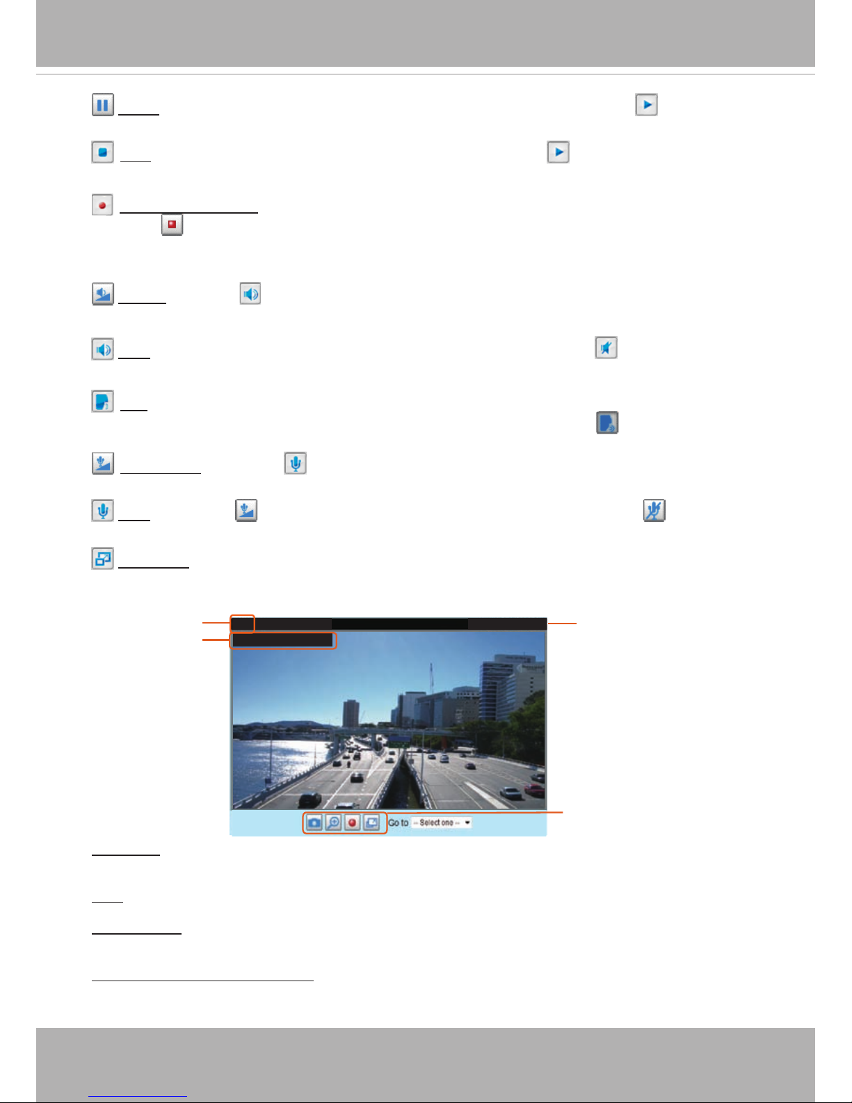
Pause: Pause the transmission of the streaming media. The button becomes the Resume button
after clicking the Pause button.
Stop: Stop the transmission of the streaming media. Click the Resume button to continue
transmission.
Start MP4 Recording: Click this button to record video clips in MP4 file format to your computer.
Press the
Stop MP4 Recording button to end recording. When you exit the web browser, video
recording stops accordingly. To specify the storage destination and le name, please refer to MP4 Saving
Options on page 27 for details.
Volume: When the Mute function is not activated, move the slider bar to adjust the volume on the
local computer.
Mute: Turn off the volume on the local computer. The button becomes the Audio On button after
clicking the Mute button.
Talk: Click this button to talk to people around the Network Camera. Audio will project from
the external speaker connected to the Network Camera. Click this button
Audio will project from
again to end talking
transmission.
Mic Volume: When the Mute function is not activated, move the slider bar to adjust the
microphone volume on the local computer.
Mute: Turn off the Mic volume on the local computer. The button becomes the Mic On button
after clicking the Mute button.
Full Screen: Click this button to switch to full screen mode. Press the “Esc” key to switch back to normal
mode.
■ The following window is displayed when the video mode is set to MJPEG:
Video Title: The video title can be congured. For more information, please refer to Media > Image on
page 68.
Time: Display the current time. For more information, please refer to Media > Image on page 68.
Title and Time: Video title and time can be stamped on the streaming video. For more information, please
refer to Media > Image on page 68
.
Video and Audio Control Buttons: Depending on the Network Camera model and Network Camera
conguration, some buttons may not be available.
Video 17:08:56 2011/03/10
Title and Time
2011/03/10 17:08:56
Time
Video (HTTP-V)
Video Title
Video Control Buttons
VIVOTEK
24 - User's Manual
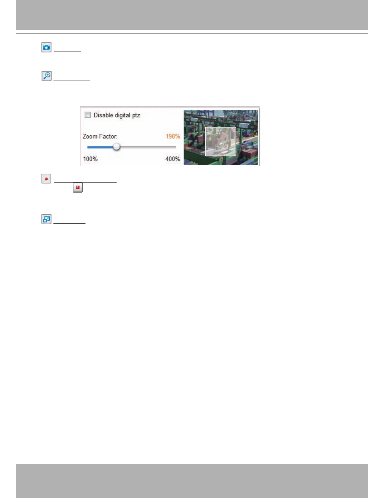
Snapshot: Click this button to capture and save still images. The captured images will be displayed
in a pop-up window. Right-click the image and choose Save Picture As to save it in JPEG (*.jpg) or BMP
(*.bmp) format.
Digital Zoom: Click and uncheck “Disable digital zoom” to enable the zoom operation. The navigation
screen indicates the part of the image being magnied. To control the zoom level, drag the slider bar. To
move to a different area you want to magnify, drag the navigation screen.
Start MP4 Recording: Click this button to record video clips in MP4 file format to your computer.
Press the
Stop MP4 Recording button to end recording. When you exit the web browser, video
recording stops accordingly. To specify the storage destination and le name, please refer to MP4 Saving
Options on page 27 for details.
Full Screen: Click this button to switch to full screen mode. Press the “Esc” key to switch back to normal
mode.
VIVOTEK
User's Manual - 25
Zoom In
Zoom Out
Click to bring into
center of view
Click, hold down the
button, and scroll
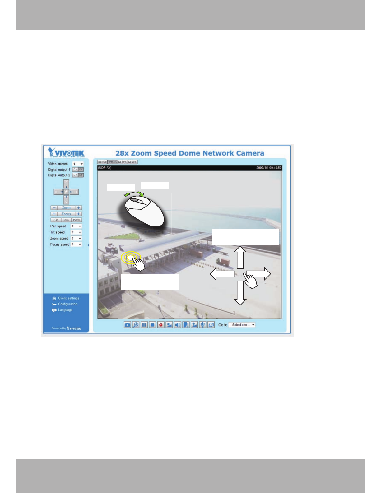
Mouse Control
In addition to a joystick and the PTZ panel, you can exert mouse control on the live view window.
Below are the supported methodologies:
1. You can quickly swipe through the screen by clicking and hold down the left mouse button, and
then move your mouse cursor toward the direction you prefer. The same method applies to the
PTZ panel buttons.
2. You can also use the mouse wheel to zoom in and zomm out on an area of interest.
3. A single click on a specic point on the screen can bring that point closer to the center of your
view window.
VIVOTEK
26 - User's Manual
Client Settings
This chapter explains how to select the stream transmission mode and saving options on the
local computer. When completed with the settings on this page, click Save on the page bottom
to enable the settings.
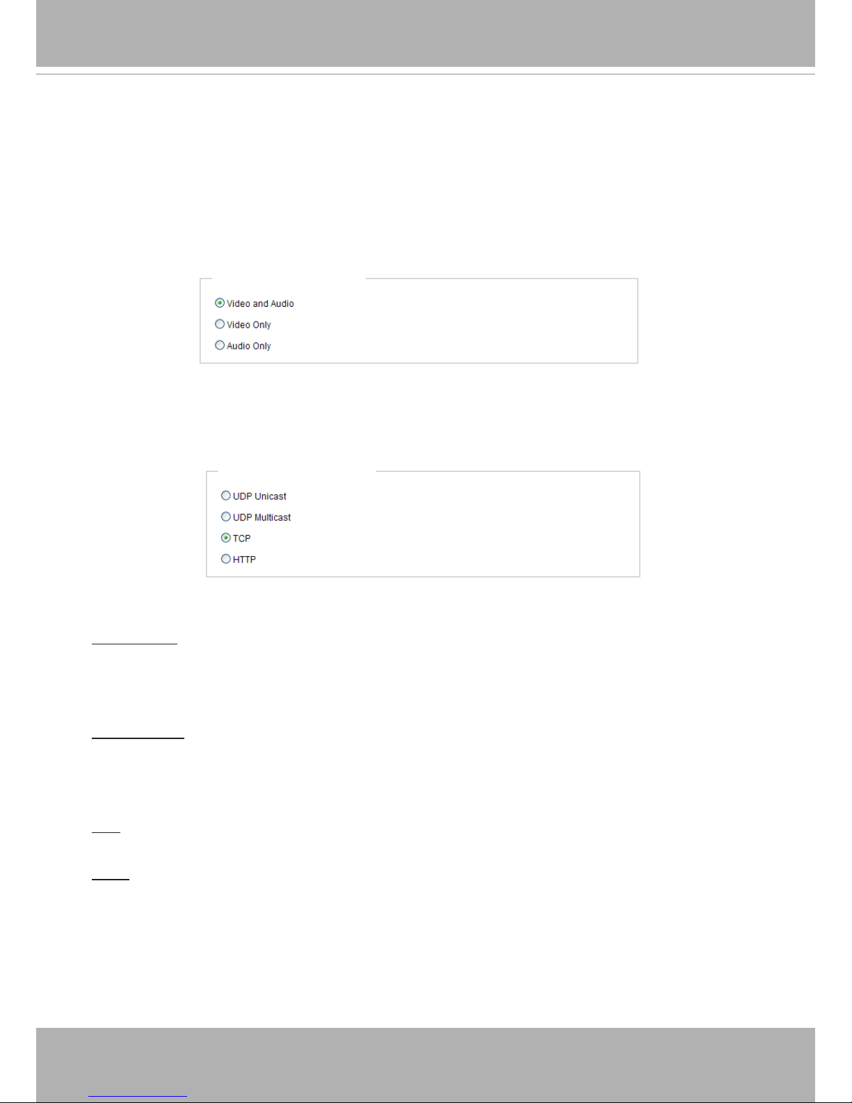
H.264 / MPEG-4 Media Options
Select to stream video or audio data or both. This is enabled only when the video mode is set to H.264 or
MPEG-4.
H.264 / MPEG-4 Protocol Options
Depending on your network environment, there are four transmission modes of H.264 or MPEG-4
streaming:
UDP unicast: This protocol allows for more real-time audio and video streams. However, network
packets may be lost due to network burst trafc and images may be broken. Activate UDP connection
when occasions require time-sensitive responses and the video quality is less important. Note that each
unicast client connecting to the server takes up additional bandwidth and the Network Camera allows up
to ten simultaneous accesses.
UDP multicast: This protocol allows multicast-enabled routers to forward network packets to all clients
requesting streaming media. This helps to reduce the network transmission load of the Network Camera
while serving multiple clients at the same time. Note that to utilize this feature, the Network Camera must
be configured to enable multicast streaming at the same time. For more information, please refer to
RTSP Streaming on page 59.
TCP: This protocol guarantees the complete delivery of streaming data and thus provides better video
quality. The downside of this protocol is that its real-time effect is not as good as that of the UDP protocol.
HTTP: This protocol allows the same quality as TCP protocol without needing to open specic ports for
streaming under some network environments. Users inside a firewall can utilize this protocol to allow
streaming data through.
H.264/MPEG-4 Media Options
H.264/MPEG-4 Protocol Options
VIVOTEK
User's Manual - 27
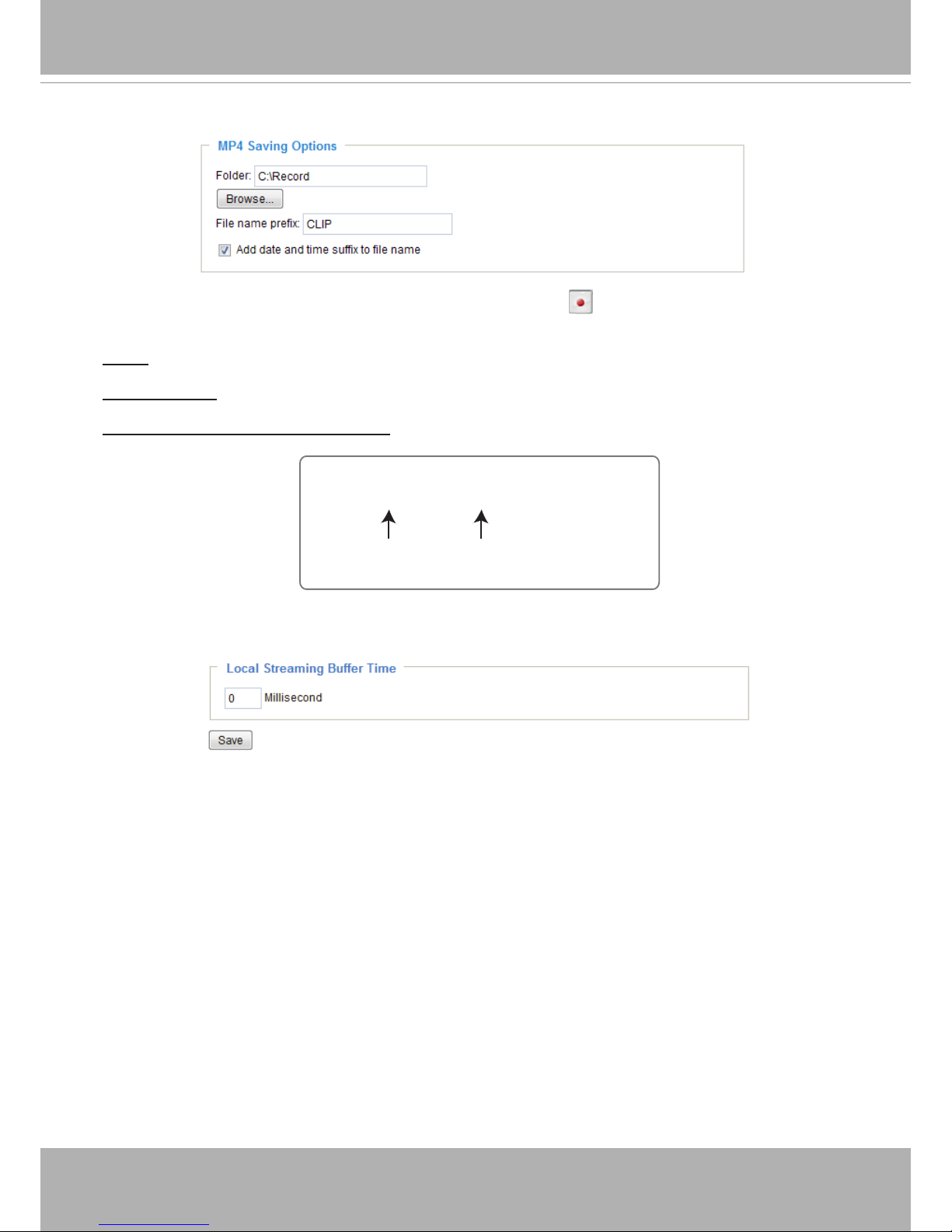
MP4 Saving Options
Users can record live video as they are watching it by clicking Start MP4 Recording on the main
page. Here, you can specify the storage destination and le name.
Folder: Specify a storage destination for the recorded video les.
File name prex: Enter the text that will be appended to the front of the video le name.
Add date and time sufx to the le name: Select this option to append the date and time to the end of the
le name.
Local Streaming Buffer Time
Due to the unsteady bandwidth ow, the live streaming may lag and not be very smoothly. If you enable
this option, the live streaming will be stored on the camera’s buffer area for a few seconds before playing
on the live viewing window. This will help you see the streaming more smoothly.
If you enter 3000 Millisecond, the streaming will delay for 3 seconds.
CLIP_20110328-180853
Date and time suffix
The format is: YYYYMMDD_HHMMSS
File name prefix
VIVOTEK
28 - User's Manual
Conguration
Click Configuration on the main page to enter the camera setting pages. Note that only
Administrators can access the configuration page. Please refer to page 40 Security > User
Account for how to congure access rights for different users.
VIVOTEK offers an easy-to-use user interface that helps you set up your network camera with
minimal effort. To simplify the setting procedure, two types of user interfaces are available:
Advanced Mode for professional users and Basic Mode for entry-level users. Some advanced
functions (PTZ/ Event/ Recording/ Local storage) are not displayed in Basic Mode.
If you want to set up advanced functions, please click [Advanced Mode] on the bottom of the
conguration list to quickly switch to Advanced Mode.
In order to simplify the user interface, the detailed information will be hidden unless you click on
the function item. When you click on the rst sub-item, the detailed information for the rst sub-
item will be displayed; when you click on the second sub-item, the detailed information for the
second sub-item will be displayed and that of the rst sub-item will be hidden.
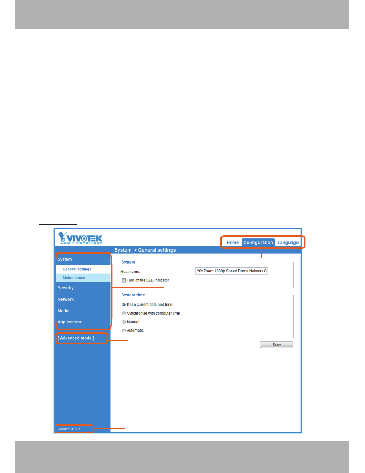
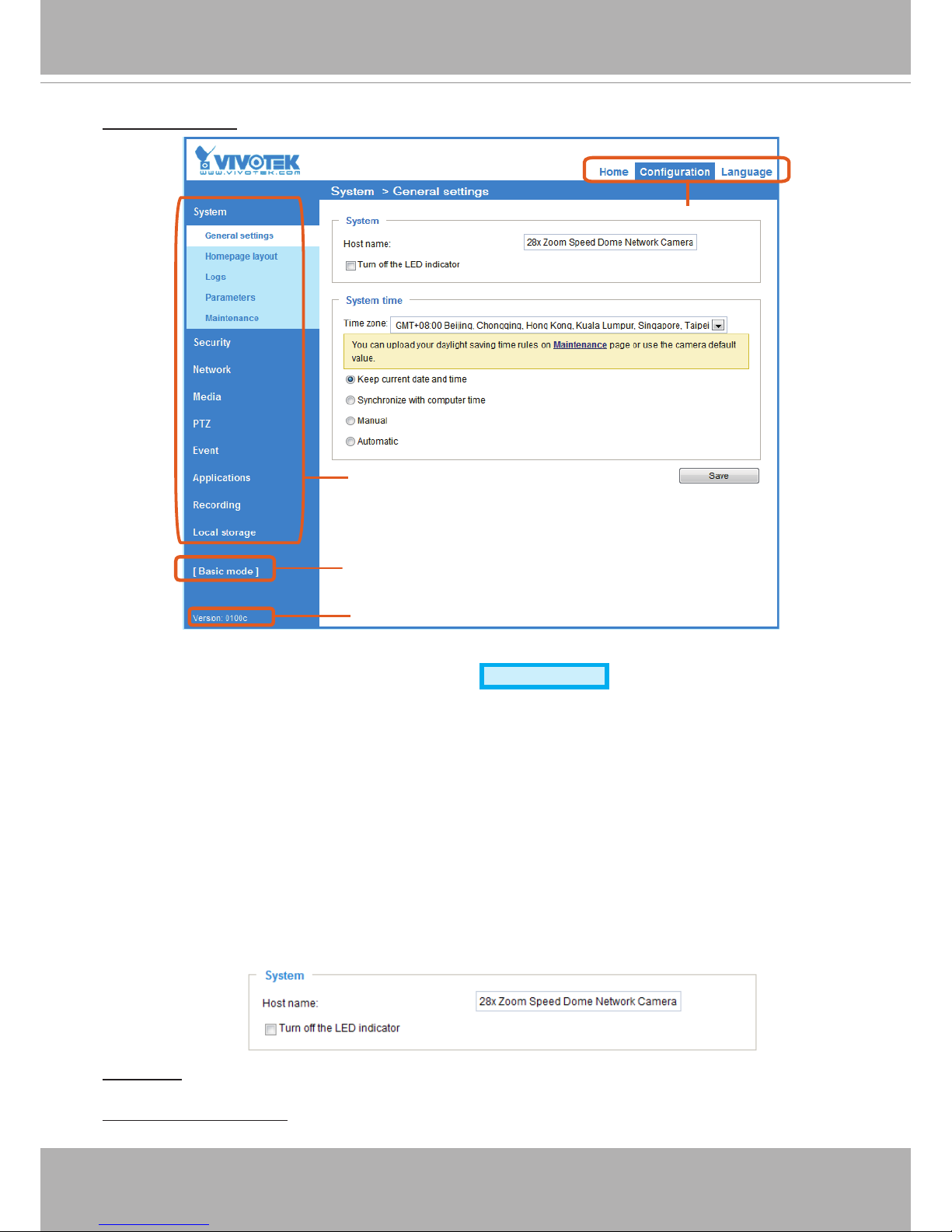
Show below are the locations of the Basic Mode and the Advanced Mode screen elements:
Basic Mode
Configuration List
Click to switch to Advanced Mode
Navigation Area
Firmware Version
VIVOTEK
User's Manual - 29
Advanced Mode
Each function on the conguration list will be explained in the following sections. Those functions that are
displayed only in Advanced Mode are marked with
Advanced Mode
. If you want to set up advanced
functions, please click [Advanced Mode] at the bottom of the conguration list to quickly switch over.
The Navigation Area provides an instant switch among Home page (the monitoring page for live
viewing), Conguration page, and multi-language selection.
System > General settings
This section explains how to congure the basic settings for the Network Camera, such as the
host name and system time. It is composed of the following two columns: System and System
Time.
System
Host name: Enter a desired name for the Network Camera. The text will be displayed at the top of the
main page.
Turn off the LED indicator: When checked, the onboard LED will be turned off if you do not want it to be
seen. There are cases when you do not want people to know if the camera is operating.
Configuration List
Click to switch to Basic Mode
Firmware Version
Navigation Area
VIVOTEK
30 - User's Manual
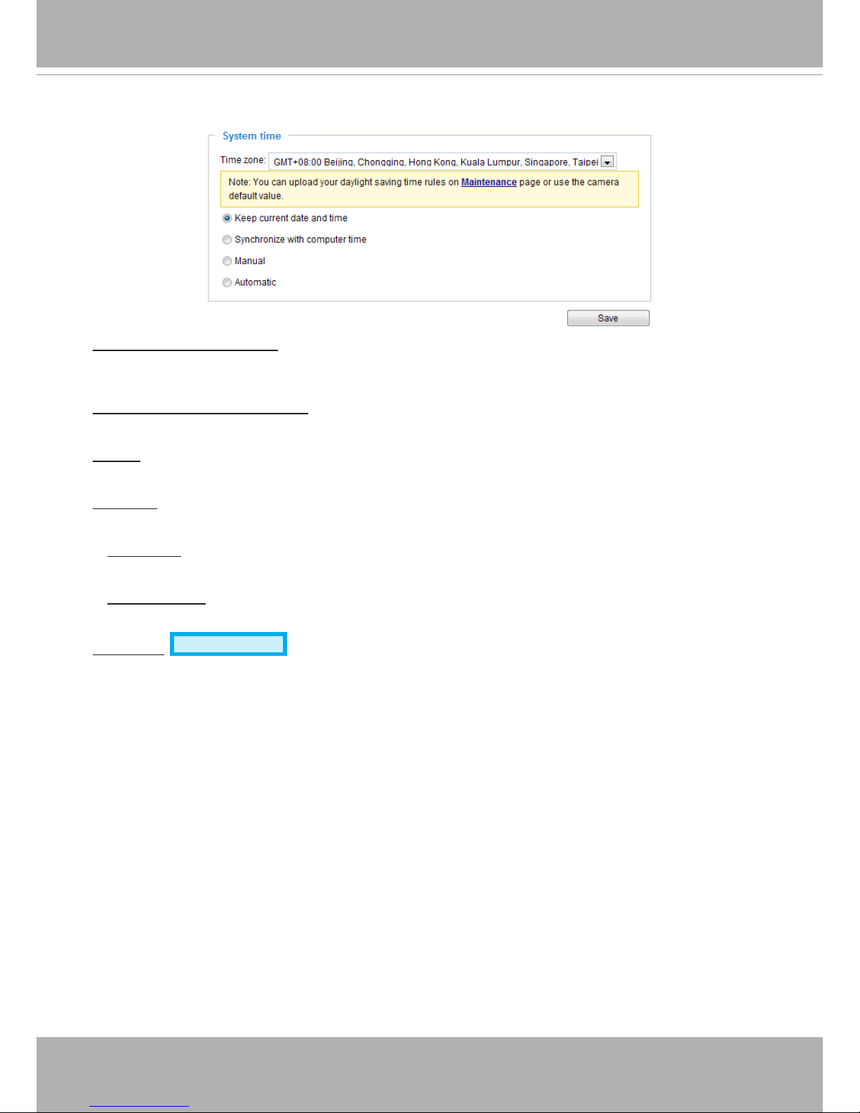
System time
Keep current date and time: Select this option to preserve the current date and time of the Network
Camera. The Network Camera’s internal real-time clock maintains the date and time even when the
power of the system is turned off.
Synchronize with computer time: Select this option to synchronize the date and time of the Network
Camera with the local computer. The read-only date and time of the PC is displayed as updated.
Manual: The administrator can enter the date and time manually. Note that the date and time format are
[yyyy/mm/dd] and [hh:mm:ss].
Automatic: The Network Time Protocol is a protocol which synchronizes computer clocks by periodically
querying an NTP Server.
NTP server: Assign the IP address or domain name of an established time server. Leaving the text box
blank connects the Network Camera to the default time servers.
Update interval: Select to update the time using the NTP server on an hourly, daily, weekly, or monthly
basis.
Time zone
Advanced Mode
: Select the appropriate time zone from the list. If you want to upload
Daylight Savings Time rules, please refer to System > Maintenance > Import/ Export les on page 37
for details.
When nished with the settings on this page, click Save at the bottom of the page to enable the settings.
 Loading...