

Page 1
Quick Installation Guide
繁中 日本語
English
簡中
Français
Deutsch
Español Português
SD8111/SD8121
H.264 12x Zoom Day&Night 3D Noise Reduction
Italiano
Türkçe
Polski
Русский
Česky Svenska
Page 2
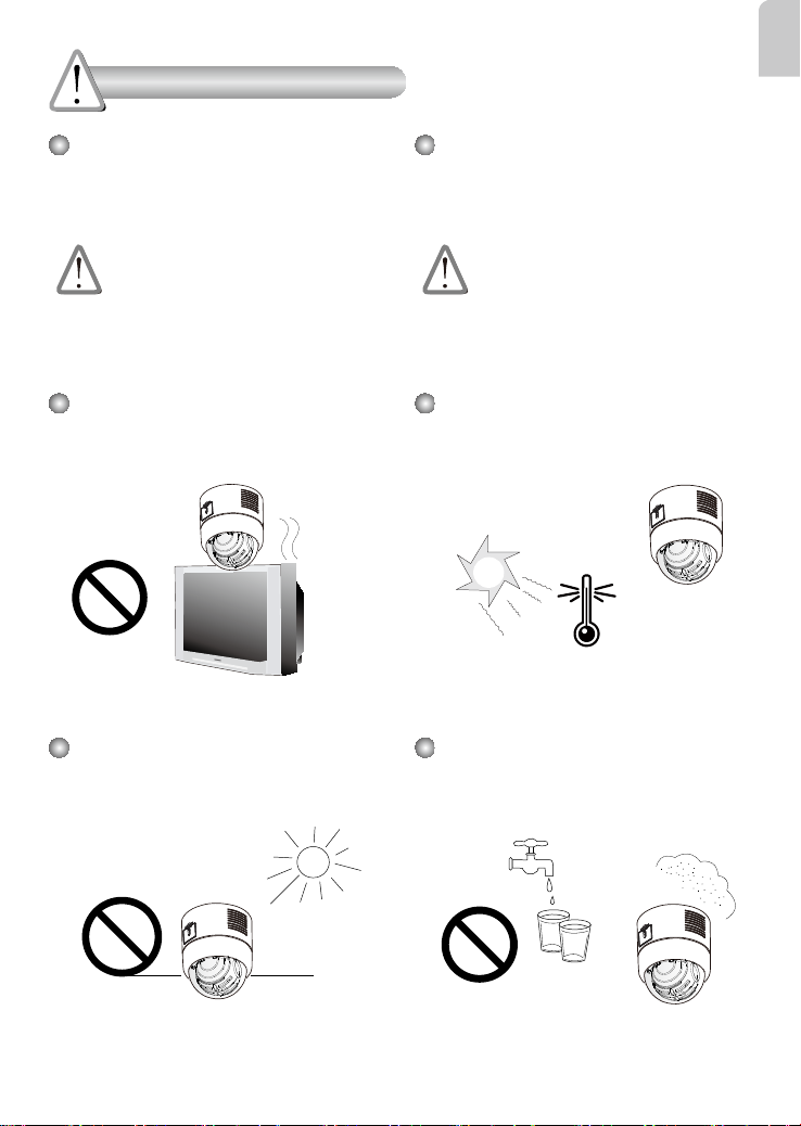
Warning Before Installation
English
Power off the Network Camera as
soon as smoke or unusual odors are
detected.
Contact your distributor in the event of
occurrence.
Do not place the Network Camera
around heat sources, such as a
television or oven.
Keep the Network Camera away from
direct sunlight.
Keep the Network Camera away
from water. If the Network Camera
becomes wet, power off immediately.
Contact your distributor in the event of
occurrence.
Refer to your user's manual for the
operating temperature.
Do not place the Network Camera in
high humidity environments.
EN - 1
Page 3
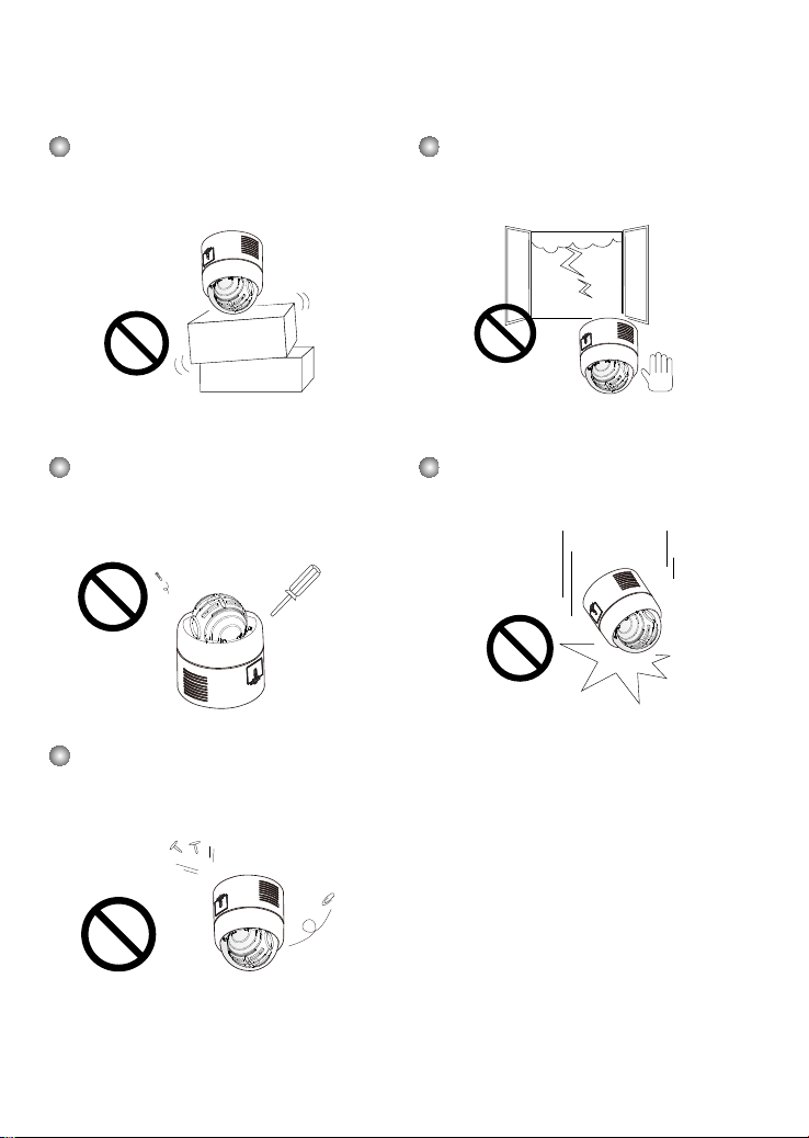
Do not place the Network Camera on
unsteady surfaces.
Do not touch the Network Camera
during a lightning storm.
Do not disassemble the Network
Camera.
Do not insert sharp or tiny objects
into the Network Camera.
Do not drop the Network Camera.
EN - 2
Page 4
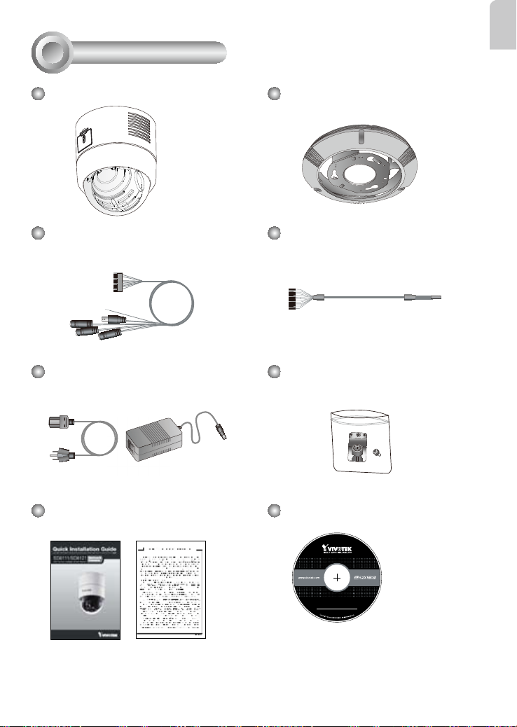
Package Contents
1
English
SD8111 / SD8121
Cable Connector (Power, Video Out,
Mic In, Audio Out, Ground)
Power Adaptor
Hard Ceiling Mount Bracket and
Decoration Ring
DI/DO Cable Connector
Fixing Plate
Quick Installation Guide /
Warranty Card
EN - 3
Software CD
5
1
0
G
0
0
1
0
2
0
Page 5

Physical Description
2
SD/SDHC Card Slot
Record the MAC address before
installing the camera.
0002D107258A
Lens
Dome Cover
EN - 4
Ethernet 10/100 RJ45 Socket
Reset Button
Restore Button
Cable Connector Socket
Page 6

Hardware Installation
3
Follow the steps below to install the Network Camera to the ceiling:
1. Detach the Decoration Ring from the Hard Ceiling Mount Bracket.
2. Align the three holes on the Mount Bracket, mark the screws locations on the ceiling.
3. Drill three pilot holes into the ceilling and hammer the plastic anchors into the holes.
4. Fix the Mount Bracket with three screws.
English
1
4
2
3
EN - 5
Page 7

5. Put the decoration ring onto the dome body.
6.Insertthexingplateintothegrooveasshownbelow.
7.Alignthethreeholestoscrewthexingplatetothedomebase.
5
0002D107258A
6
7
0002D107258A
EN - 6
Page 8

8. If you have external devices such as sensors and alarms, connect them to the general
I/O terminal block. Then connect the cable connector and Ethernet cable to the dome
base.
9. Align plate A and plate B, use hole a ~ c to hook the Network Camera on the ceiling
mount bracket.
Pin Denitions of Cable Connector
2 4
22
8
English
1 3
12: DI 0
13: DI 2
14: DI 1
15: DI 3
16: DO
21
0002D107258A
A
8
9
B
9
a
0002D107258A
EN - 7
b
c
Page 9

10.Tightenthescrewonthexingplate.
11. Align the three holes to mount the decoration ring.
10
12. Connect the cables and make the network deployment.
Ground
Power Cord Socket
BNC Video Out
Microphone In (pink)
Audio Out (green)
Ethernet 10/100 RJ45 Plug
POWER
COLLISION
1
11
LINK
RECEIVE
2
PARTITION
3
4
5
EN - 8
Ethernet Switch
Page 10

4
Assigning an IP Address
1. Install “Installation Wizard 2” from the Software Utility directory on the software CD.
2. The program will conduct an analysis of your network environment. After your network is
analyzed, please click on the “Next” button to continue the program.
Installation
Wizard 2
3. The program will search for VIVOTEK Video Receivers, Video Servers, and Network
Cameras on the same LAN.
4. After searching, the main installer window will pop up. Click on the MAC that matches the
one labeled on the bottom of your device to connect to the Network Camera via Internet
Explorer.
English
0002D107258A
00-02-D1-07-25-8A 192.168.5.151 SD8121
0002D107258A
EN - 9
Page 11

5
Ready to Use
1. Access the Network Camera on the LAN.
2. Retrieve live video through a web browser or recording software.
2010/06/09 10:25:23
For further setup, please refer to the user's manual on the software CD.
EN - 10
Page 12

Copyright 2010 VIVOTEK INC. All rights reserved.
c
P/N: 625012000G Ver.1.0
 Loading...