

Page 1
Page 2
Warning Before Installation
English
Power off the Network Camera
assoon as smoke or unusual odors
are detected.
Do not place the Network Camera
around heat sources, such as a
television or oven.
Keep the Network Camera away from
direct sunlight.
Do not place the Network Camera on
unsteady surfaces.
Do not disassemble the Network
Camera.
Do not insert sharp or tiny objects
into the Network Camera.
Keep the Network Camera away
from water. If the Network Camera
becomes wet, power off immediately.
Do not place the Network Camera in
high humidity environments.
Do not touch the Network Camera
during a lightning storm.
Do not drop the Network Camera.
Do not manually pan and tilt the
Network Camera when the power is
on.
EN - 1
Page 3
5
0
0
0
2
4
7
0
1
G
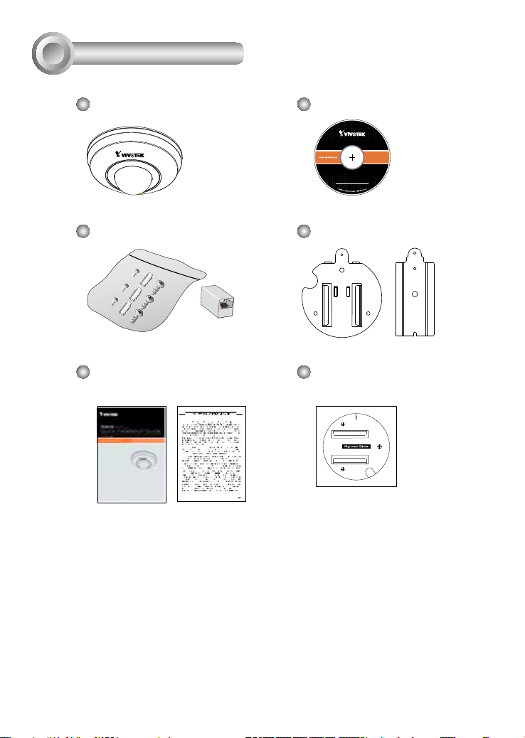
Package Contents
1
PD8136 Software CD
Screws & RJ-45 Coupler Ceiling Mount Brackets
Quick Installation Guide /
Alignment Sticker
Warranty Card
Home Position
Drill hole
Drill hole
Cable
hole
Drill hole
P/N : 62xxxxxxxx
EN - 2
Page 4

Physical Description
2
Top View
Lens
Bottom View
English
Built-in Microphone
Status LED
Ethernet 10/100
RJ-45 cable
MicroSD/SDHC Socket
Reset Button
EN - 3
Page 5

Hardware Installation
3
Mounting Plate and Camera Orientation
When installing the camera, orient the default front on the alignment sticker and the
mounting plate (illustrated below) towards the area of your interest. The camera lens’
central position is aligned with the VIVOTEK logo on the dome cover.
The Default Front
180° Pan
0°
Stop Point
The Default FrontThe Default Front
P/N : 62xxxxxxxx
Home Position
Drill hole
Cable
hole
Drill hole
180° Pan
Drill hole
EN - 4
Page 6

Install MicroSD Card
Open the MicroSD card plastic cover at the bottom using a small flathead screwdriver.
Flip the socket cover forward and up. Insert a MicroSD card, close the cover, and
push it back to secure the installation. Install the plastic cover by pressing it back to its
original position.
icro
M
SD
English
EN - 5
Page 7

Mounting the Network Camera
1. Attach base plate "A" of the ceiling mount bracket to the bottom of camera and
secure it with two small round head screws. Note that the guiding edge of the base
plate (where a screw hole is available) must protrude from the edge of camera.
2. Use the included alignment sticker, orient the sticker toward the direction you prefer.
3. Drill three holes into the ceiling; hammer the plastic anchors into the holes.
4. Install ceiling mounting plate "B" to the ceiling with three screws.
5. Slide the Network Camera into mounting plate "B."
6. Secure the camera to the mounting plate with a small screw.
2
Home Position
Drill hole
Drill hole
Cable
hole
Drill hole
P/N : 62xxxxxxxx
A B
3
6
4
5
1
EN - 6
Page 8

Network Deployment
4
Power over Ethernet (PoE)
When using a PoE-enabled switch
This Network Camera is PoE-compliant, allowing transmission of power and data via
a single Ethernet cable. Follow the below illustration to connect the camera to a PoE
enabled switch via Ethernet cable.
English
POWER
LINK
COLLISION
RECEIVE
1
2
PARTITION
3
4
5
PoE Switch
When using a non-PoE switch
Use a PoE power injector (optional) to connect between the Network Camera and a
non-PoE switch.
PoE Power Injector
(optional)
Non-PoE Switch
POWER
LINK
COLLISION
RECEIVE
1
2
PARTITION
3
4
5
EN - 7
Page 9

Assigning an IP Address
5
1. Install “Installation Wizard 2” from the Software Utility directory on the software CD.
2. The program will conduct an analysis of your network environment. After your network is
analyzed, please click on the “Next” button to continue the program.
3. The program will search for VIVOTEK Video Receivers, Video Servers, and Network
Cameras on the same LAN.
4. After a brief search, the main installer window will pop up. Double-click on the MAC
address that matches the one printed on the camera label or the S/N number on the
package box label to open a browser management session with the Network Camera.
Ready to Use
6
1. A browser session with the Network Camera should prompt as shown below.
2. You should be able to see live video from your camera. You may also install the
32-channel recording software from the software CD in a deployment consisting of
multiple cameras. For its installation details, please refer to its related documents.
For further setup, please refer to the user's manual on the software CD.
EN - 8
Page 10

 Loading...