

Vivotek IP8361 User Manual
Bullet
IP8361
Network Camera
User’s Manual
2MP • Outdoor • Day & Night
Cable Management
Rev. 1.1

VIVOTEK
Table of Contents
Overview.......................................................................................................................................................4
Read Before Use ..................................................................................................................................... 4
Package Contents ................................................................................................................................... 4
Revision History ......................................................................................................................................4
Symbols and Statements in this Document ............................................................................................. 5
Physical Description ................................................................................................................................ 6
Cabling Assembly .................................................................................................................................... 9
Hardware Installation ............................................................................................................................. 10
Network Deployment ............................................................................................................................. 12
Software Installation .............................................................................................................................. 15
Ready to Use ......................................................................................................................................... 16
Accessories ........................................................................................................................................... 18
Accessing the Network Camera .................................................................................................................19
Using Web Browsers .............................................................................................................................19
Using RTSP Players ..............................................................................................................................22
Using 3GPP-compatible Mobile Devices ............................................................................................... 23
Using VIVOTEK Recording Software .................................................................................................... 24
Main Page ..................................................................................................................................................25
Client Settings ............................................................................................................................................29
Conguration ..............................................................................................................................................31
System ..................................................................................................................................................32
Security .................................................................................................................................................34
HTTPS (Hypertext Transfer Protocol over SSL) ...................................................................................35
SNMP (Simple Network Management Protocol) ..................................................................................40
Network .................................................................................................................................................41
DDNS ....................................................................................................................................................56
Access List ...........................................................................................................................................58
Audio and Video ....................................................................................................................................61
Motion Detection ...................................................................................................................................74
Camera Tampering Detection ............................................................................................................... 77
PTZ ........................................................................................................................................................ 78
Homepage Layout ................................................................................................................................ 85
Application ............................................................................................................................................ 88
Recording ........................................................................................................................................... 101
Local Storage .....................................................................................................................................105
System Log ........................................................................................................................................109
View Parameters ................................................................................................................................ 110
Maintenance ........................................................................................................................................ 111
2 - User's Manual

VIVOTEK
Appendix ................................................................................................................................................................. 115
URL Commands for the Network Camera .......................................................................................................... 115
Technical Specications ..................................................................................................................................... 172
Technology License Notice ................................................................................................................................. 173
Electromagnetic Compatibility (EMC) ................................................................................................................. 174
User's Manual - 3

VIVOTEK
Overview
VIVOTEK IP8361 is a high-end 2-megapixel network bullet camera surveillance. outdoor-specic features
such as concealed wiring to prevent tampering, the IP8361 is the camera of choice for applications such
as parking lots, gas stations, and building entrances.
The IP8361 boasts high-definition 2-megapixel (1600 x 1200) resolution, allowing for the delivery of
extremely detailed images and coverage 6 times larger than a VGA camera. To maximize the benet of
the 2-megapixel sensor, the IP8361 employs several innovative technologies for optimized bandwidth
efciency. The ePTZ function enables users to quickly move to a target area for close-up shots without
moving the camera physically. Users can also receive only the portions of the images they are interested
in via the cropping function. Furthermore, multiple video streams can be delivered simultaneously in
different resolutions, frame rates, and image qualities for viewing on different platforms so as to meet
different needs or bandwidth constraints. The IP8361 also offers activity adaptive streaming support that
dynamically allocates bandwidth according to the video content and trigger state.
Aimed at outdoor surveillance, the IP8361 features auto-iris capability to protect the lens from damage
induced by direct sunlight. To adapt to light changes throughout the day, the camera is furnished with
a removable IR-cut filter and IR illuminators for superior image quality around the clock. The IP8361
also comes with an IP66-rated housing that offers protection against rain and dust to ensure functional
operation in all types of weather conditions. For easy management and protection against tempering
and vandalism, the IP8361 is also equipped with a mounting bracket that conceals all cables within the
bracket.
With other advanced features such as tamper detection, 802.3af compliant PoE, SD/SDHC card on-
board storage, and two-way audio via SIP protocol, the IP8361 is a full-edged surveillance solution for
outdoor environments.
Read Before Use
The use of surveillance devices may be prohibited by law in your country. The Network Camera is not
only a high-performance web-ready camera but can also be part of a exible surveillance system. It is
the user’s responsibility to ensure that the operation of such devices is legal before installing this unit for
its intended use.
It is important to rst verify that all contents received are complete according to the Package Contents
listed below. Take note of the warnings in the Quick Installation Guide before the Network Camera is
installed; then carefully read and follow the instructions in the Installation chapter to avoid damage due to
faulty assembly and installation. This also ensures the product is used properly as intended.
The Network Camera is a network device and its use should be straightforward for those who have basic
networking knowledge. It is designed for various applications including video sharing, general security/
surveillance, etc. The Configuration chapter suggests ways to best utilize the Network Camera and
ensure proper operations. For creative and professional developers, the URL Commands of the Network
Camera section serves as a helpful reference to customizing existing homepages or integrating with the
current web server.
Package Contents
■ IP8361 with an RJ45 Cable
■ Sun Shield
■ Wall Mount Bracket
■ Waterproof Connector for RJ45 Ethernet Enclosure
■ Alignment Sticker / Silica Gel Desiccant bag
■ Waterproof Connector (for backup use)
■ Software CD
■ Quick Installation Guide / Warranty Card
4 - User's Manual

VIVOTEK
i
Revision History
Rev. 1.0: Initial release
Rev. 1.1: Removed DC power adapter from the package contents; added DO connection diagrams.
Symbols and Statements in this Document
INFORMATION: provides important messages or advices that might help prevent inconvenient
or problem situations.
NOTE: Notices provide guidance or advices that are related to the functional integrity of the
machine.
Tips: Tips are useful information that helps enhance or facilitae an installation, function, or
process.
WARNING or IMPORTANT: These statements indicate situations that can be dangerous or
hazardous to the machine or you.
Electrical Hazard: This statement appears when high voltage electrical hazards might occur
to an operator.
User's Manual - 5
VIVOTEK
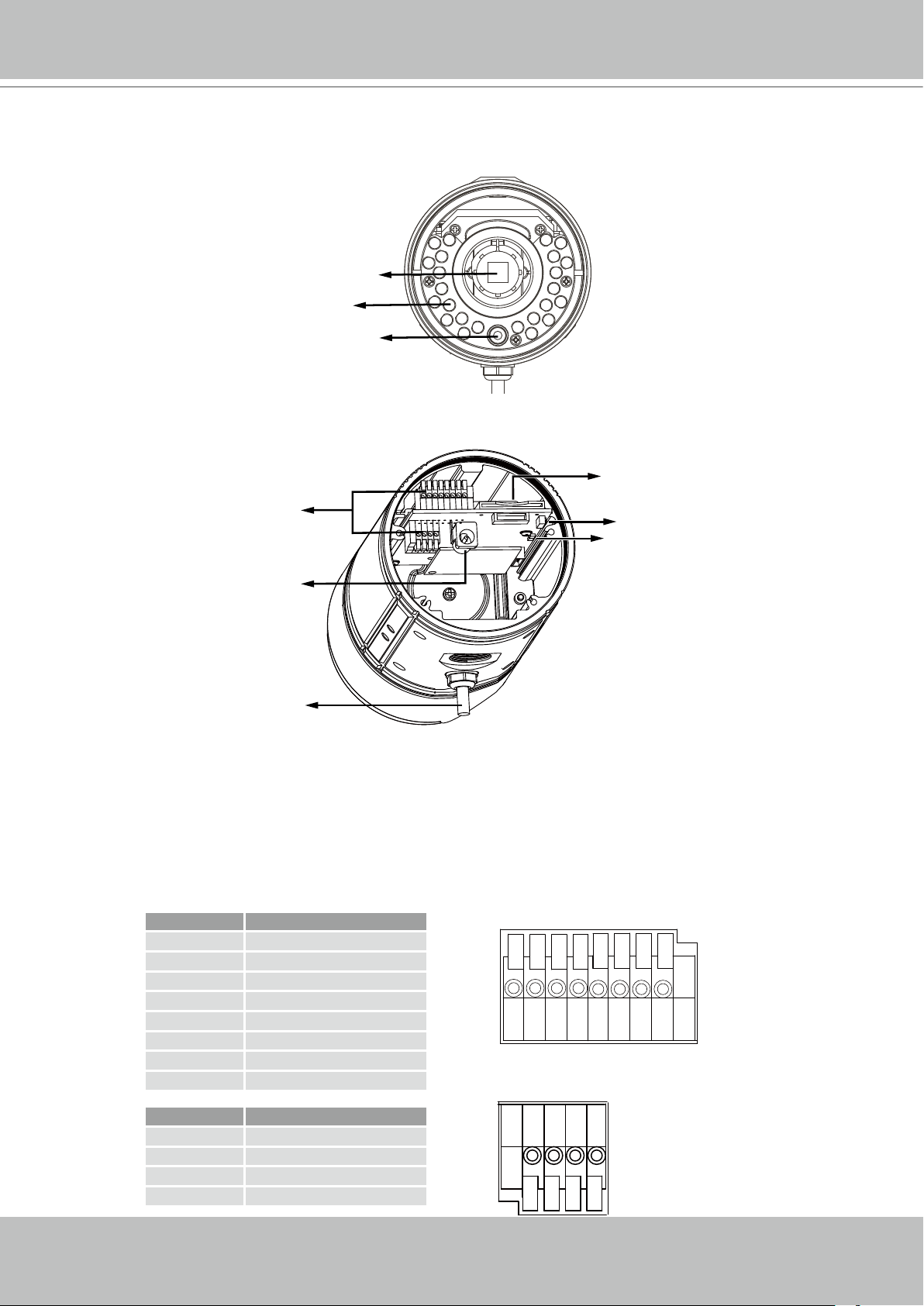
Physical Description
IR LEDs
Light Sensor
General I/O
Terminal Block
Lens
SD/SDHC/SDXC
Card Slot
Reset Button
Status LED
Power Cord Socket
RJ45 Cable
General I/O Terminal Block
This Network Camera provides a general I/O terminal block which is used to connect external
input / output devices. The pin denitions are described below.
Pin Name
1 Power +12V
2 Digital Output
3 Digital Input
4 Ground
5 AC 24V Input
6 AC 24V Input
7 RS-485 +
8 RS-485 -
87654321
6 - User's Manual
Pin Name
1 External MIC In
2 Ground
3 Audio Out
4 Ground
4321
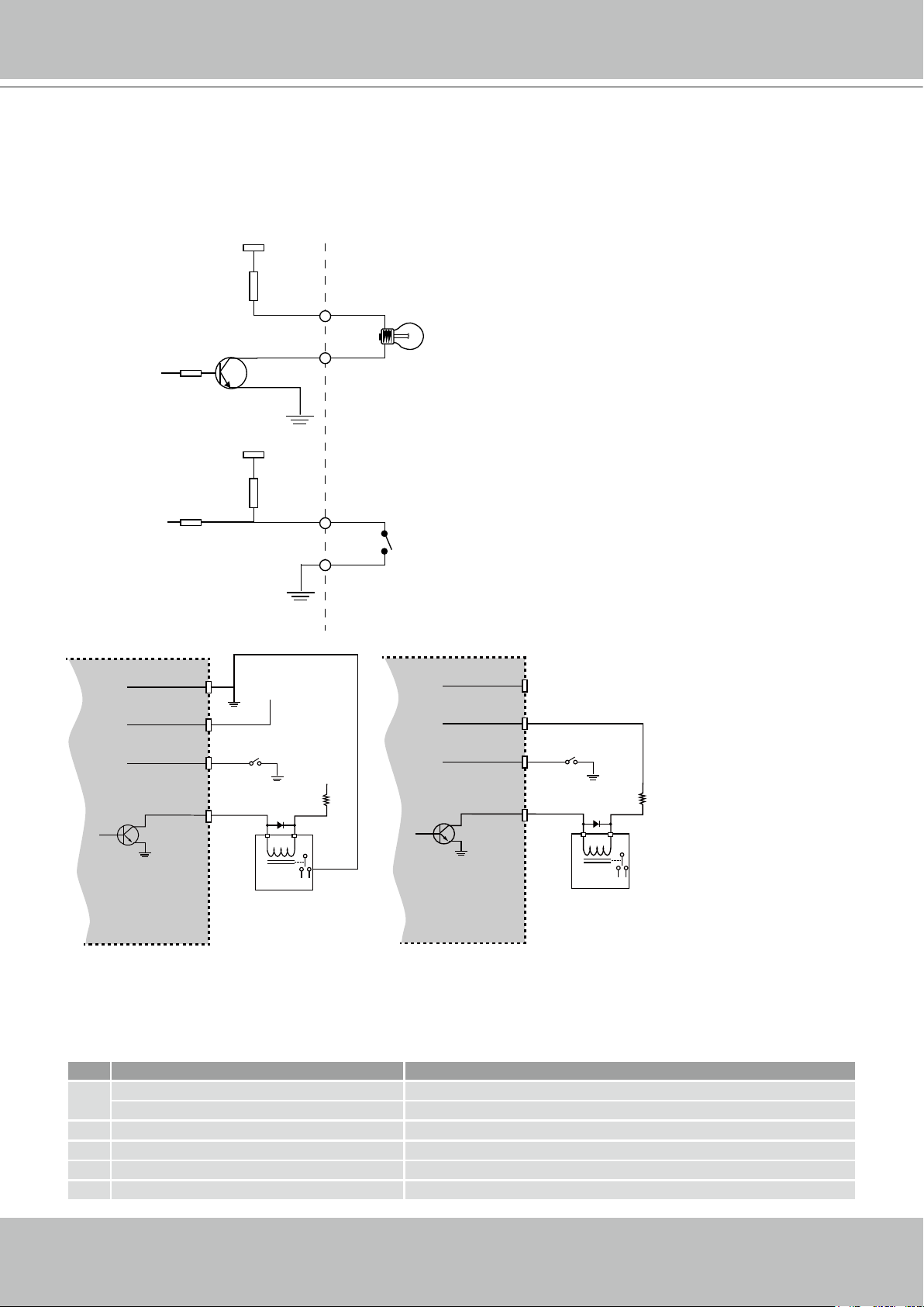
DI/DO Diagram
12V
Please refer to the following illustration for the connection method.
PIN 1
Power+12V
PIN 2
Digital output
+12V
VIVOTEK
Camera Power
BJT transistor
Gnd
Input
Output
PIN 3
Digital input
PIN 4
Ground
Gnd
Input
Output
4
1
VDC
Relay
+12
VDC
3
Switch
2
4
VDC
1
Relay
+30
VDC
Max.
BJT transistor
3
Switch
2
Camera Power
Status LED
The LED indicates the status of the Network Camera.
Item LED status Description
Steady Red Power on and system booting
1
Red LED Off Power off or power is supplied but the network is disconnected.
2 Steady Red Network works (heartbeat)
3 Red Blinks every 2 sec. Audio mute (heartbeat)
4 Blink Red every 0.15 sec. Upgrading Firmware
5 Blink Red every 0.15 sec. Restoring default
User's Manual - 7
VIVOTEK
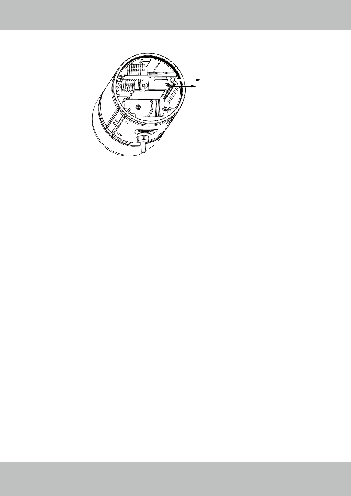
Hardware Reset
Reset Button
Status LED
The reset button is used to reset the system or to restore factory defaults. Sometimes resetting
the system can return the camera to normal operation. If the system problems remain after
reset, restore the factory settings and install again.
Reset: Press and release the recessed reset button with a paper clip or thin object. Wait for the
Network Camera to reboot.
Restore: Press and hold the recessed reset button until the status LED rapidly blinks. It takes
about 30 seconds. Note that all settings will be restored to factory default. Upon successful
restore, the status LED will blink red during normal operation.
SD/SDHC Card Capacity
This network camera is compliant with SD/SDHC/SDXC 16GB / 8GB and other preceding
standard SD cards.
8 - User's Manual
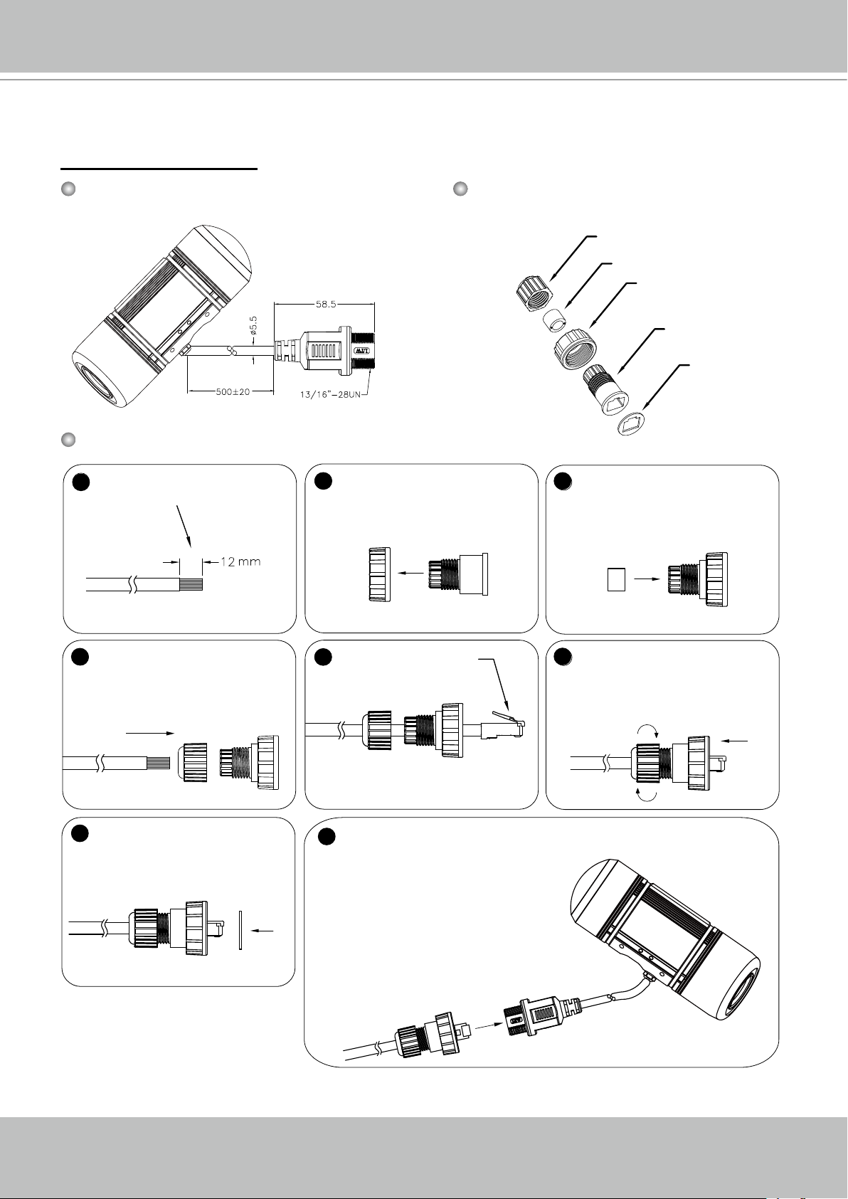
Cabling Assembly
RJ45 Cable Connector
VIVOTEK
RJ45 Cable Dimension (unit: mm)
Assembling Steps
1
Prepare an Ethernet cable
and strip part of the sheath.
2
Components of the Waterproof
Connector
Insert the housing into the
screw nut.
(C)
(D)
Sealing Nut (A)
Seal (B)
Screw Nut (C)
Housing (D)
Gasket (E)
3
Insert the seal into the housing.
(B)
Recommended cable gauge: 24AWG
(0.51 mm)
Insert the stripped Ethernet
4
cable through the sealing
nut and the housing.
(A)
7
Attach the gasket to the front
of the housing.
(E)
5
Clamp the cable with
an RJ45 plug.
Connect the Ethernet cable to the RJ45 cable and secure the
8
connectors tightly.
6
Push the RJ45 plug into the
housing, then secure the
sealing nut tightly.
User's Manual - 9
VIVOTEK
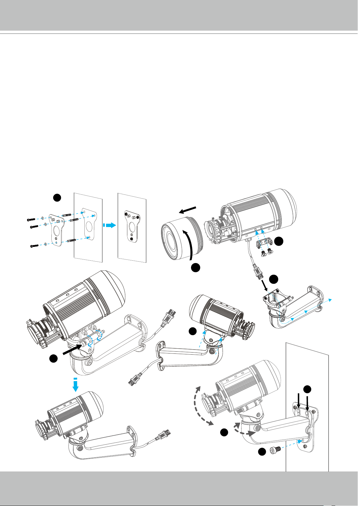
Hardware Installation
1. Attach the alignment sticker to the wall. Drill four holes into the wall. Then hammer the
supplied plastic anchors into the holes and secure the plate with supplied screws.
2. Fix the intersection bracket to the side of the Network Camera with two screws.
3. Feed the RJ45 cable through the front opening of the wall mount bracket. (If you want to use
external devices such as sensors and alarms, please refer to the assembling steps on the
next page.)
4. Open the lens cover.
5. Push the spring mortise and hook the bracket onto the groove of the wall mount bracket.
6. Secure the two screws on the other side of the wall mount bracket.
7. Hang the wall mount bracket on the plate.
8. Fix the wall mount bracket with the supplied screws.
9. Adjust the angle of the wall mount bracket to aim at the area of interest.
1
2
4
3
6
5
7
10 - User's Manual
9
8
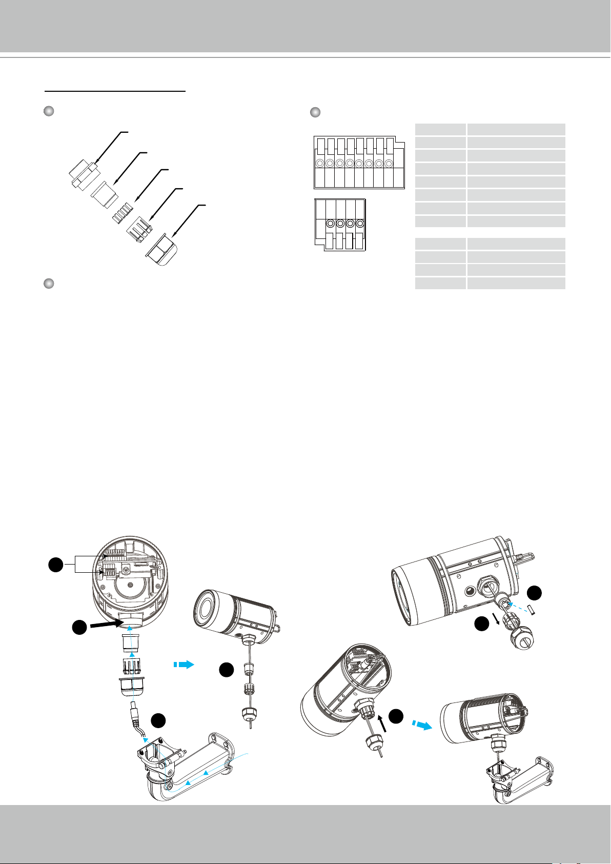
Waterproof Connector
VIVOTEK
Components of the Waterproof Connector
Screw Nut (A)
Seal (B)
Seals (C)
Housing (D)
Sealing Nut (E)
Assembling Steps
Pin Denition
87654321
4321
1 Power +12V
2 Digital Output
3 Digital Input
4 Ground
5 AC 24V
6 AC 24V
7 RS485 +
8 RS485 -
1 External MIC In
2 Ground
3 Audio Out
4 Ground
1. Disassemble the components of the waterproof connector into part (A) ~ (E) as shown above.
2. Open the back cover of the Network Camera.
3. Remove the rubber stopper from the bottom of the Network Camera and secure the screw nut
(A) tightly.
4. If you need extra power for external devices, please feed the power cable through the wall
mount bracket and the waterproof connector (E --> D --> B --> A) as the illustration shown
below. Then connect the power cord to the socket. Note: There are 7 holes on the seal (B),
and the widest hole with a crack on the side is specic for power cord.
5. If you have external devices such as sensors and alarms, feed the cables through the wall
mount bracket and the waterproof connector (E --> D --> B --> A) as the illustration shown
below. Then refer to the pin denition to connect them to the general I/O terminal block. Note:
The recommended cable gauge is 2.0 ~ 2.8 mm.
6. Push the seal (B) into the housing (D).
7. Insert the seals (C) into the empty holes on the seal (B) to avoid moisture.
8. Secure the sealing nut (E) tightly.
5
7
(B)
3
(A)
(B)
(D)
(E)
4
4
8
(E)
6
(D)
User's Manual - 11
(C)
VIVOTEK
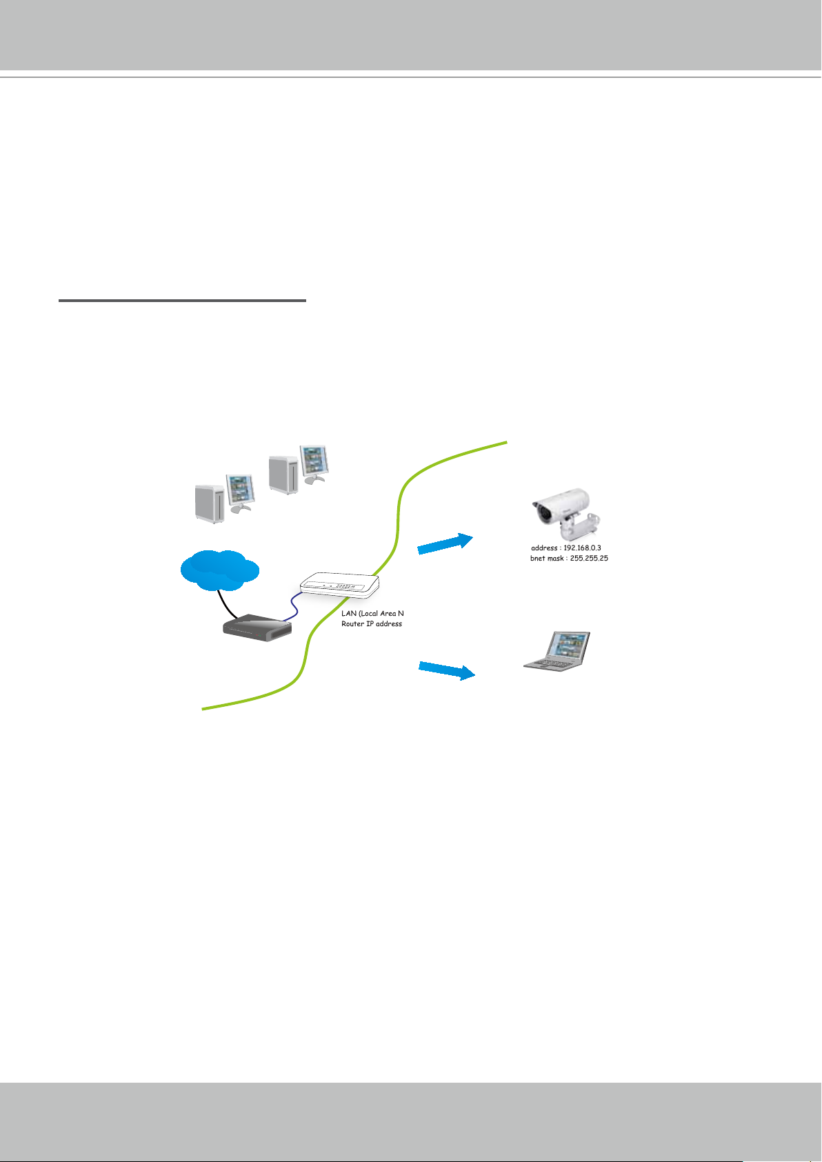
Network Deployment
Setting up the Network Camera over the Internet
There are several ways to set up the Network Camera over the Internet. The rst way is to set
up the Network Camera behind a router. The second way is to utilize a static IP. The third way is
to use PPPoE.
Internet connection via a router
Before setting up the Network Camera over the Internet, make sure you have a router and follow
the steps below.
1. Connect your Network Camera behind a router, the Internet environment is illustrated below.
Regarding how to obtain your IP address, please refer to Software Installation on page 15 for
details.
Internet
Cable or DSL Modem
WAN (Wide Area Network )
Router IP address : from ISP
LINK
POWER
COLLISION
RECEIVE
1
2
PARTITION
3
4
5
LAN (Local Area Network)
Router IP address : 192.168.0.1
IP address : 192.168.0.3
Subnet mask : 255.255.255.0
Default router : 192.168.0.1
IP address : 192.168.0.2
Subnet mask : 255.255.255.0
Default router : 192.168.0.1
2. In this case, if the Local Area Network (LAN) IP address of your Network Camera is
192.168.0.3, please forward the following ports for the Network Camera on the router.
■ HTTP port: 80
■ RTSP port: 554
■ RTP port for audio: 5558
■ RTCP port for audio: 5559
■ RTP port for video: 5556
■ RTCP port for video: 5557
If you have changed the port numbers on the Network page, please open the ports
accordingly on your router. For information on how to forward ports on the router, please refer
to your router’s documentation.
3. Find out the public IP address of your router provided by your ISP (Internet Service Provider).
Use the public IP and the secondary HTTP port to access the Network Camera from the
Internet. Please refer to Network Type on page 41 for details.
12 - User's Manual

VIVOTEK
Internet connection with static IP
Choose this connection type if you are required to use a static IP for the Network Camera.
Please refer to LAN on page 41 for details.
Internet connection via PPPoE (Point-to-Point over Ethernet)
Choose this connection type if you are connected to the Internet via a DSL Line. Please refer to
PPPoE on page 42 for details.
User's Manual - 13
VIVOTEK
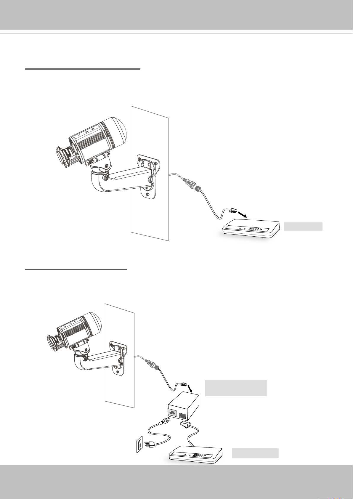
Set up the Network Camera through Power over Ethernet (PoE)
When using a PoE-enabled switch
The Network Camera is PoE-compliant, allowing transmission of power and data via a single
Ethernet cable. Follow the below illustration to connect the Network Camera to a PoE-enabled
switch via an Ethernet cable.
power + data transmission
POWER
COLLISION
LINK
RECEIVE
1
2
PARTITION
3
4
5
PoE Switch
When using a non-PoE switch
If your switch/router does not support PoE, use a PoE power injector (optional) to connect
between the Network Camera and a non-PoE switch.
PoE Power Injector
(optional)
14 - User's Manual
POWER
COLLISION
LINK
RECEIVE
1
2
PARTITION
3
4
5
Non-PoE Switch
VIVOTEK
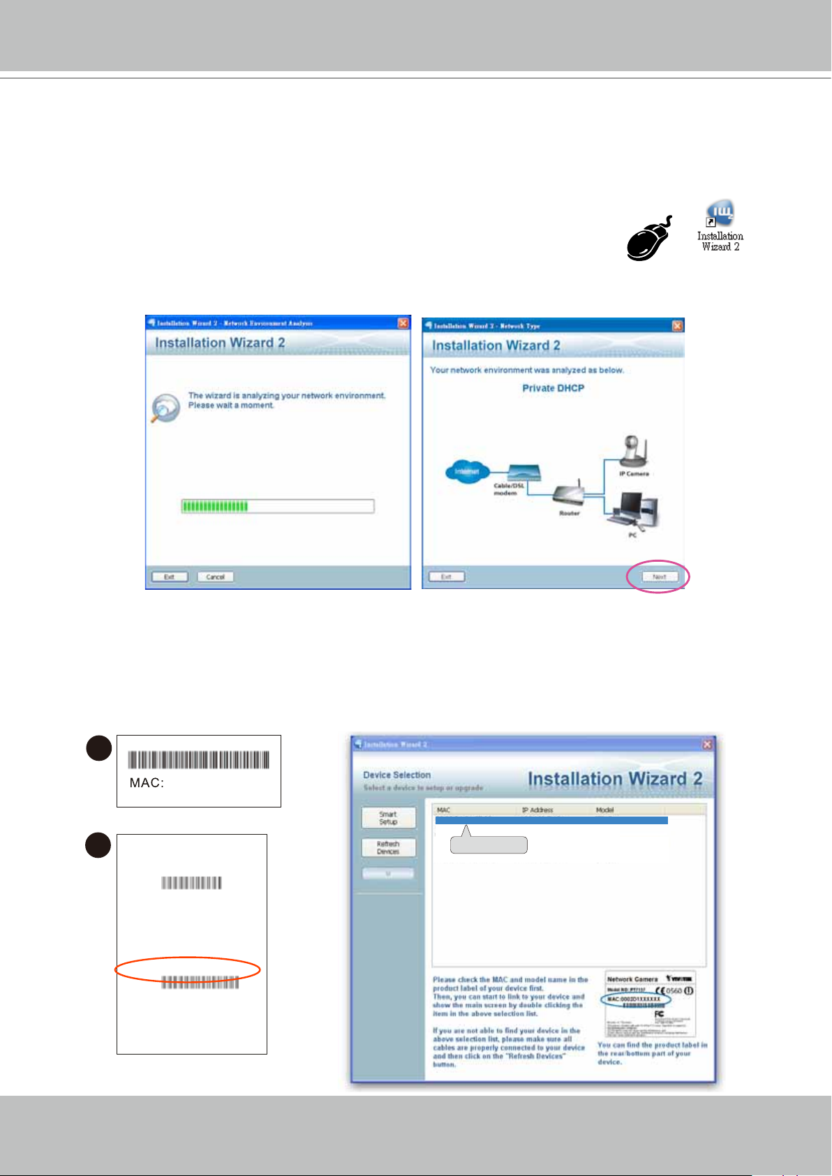
Software Installation
Installation Wizard 2 (IW2), free-bundled software included on the product CD, helps you set up
your Network Camera on the LAN.
1. Install IW2 under the Software Utility directory from the software CD.
Double click the IW2 shortcut on your desktop to launch the program.
2. The program will conduct an analysis of your network environment.
After your network environment is analyzed, please click Next to continue the program.
3. The program will search for all VIVOTEK network devices on the same LAN.
4. After searching, the main installer window will pop up. Click on the MAC and model name
which matches the product label on your device to connect to the Network Camera via
Internet Explorer.
1
0002D17151CD
00-02-D1-73-02-02 192.168.5.151 IP8361
2
Model No.: IP8361
P/ N: 10 00 436 90G
EA N: 47 12 123 671 550
Q 'ty: 1 PCS
S/ N: 00 02 D1715 1C D
F/W V er. : 010 0d
CA RTO N OF N O. 01
MAD E IN TA IWA N
/
0002D1730202
User's Manual - 15
VIVOTEK
T
W
∞
N
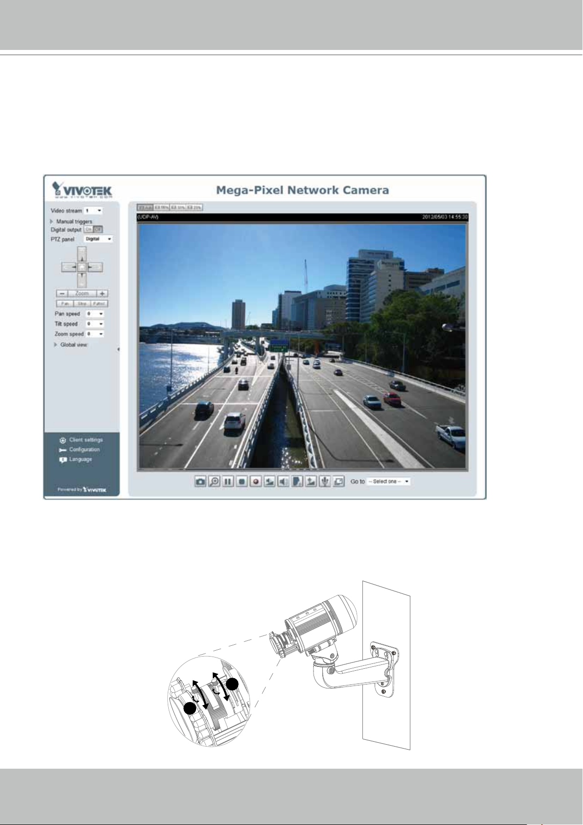
Ready to Use
1. A browser session with the Network Camera should prompt as shown below
2. You should be able to see live video from your camera. You may also install the 32-channel
recording software from the software CD in a deployment consisting of multiple cameras. For
its installation details, please refer to its related documents.
3. Unscrew the zoom controller to adjust the zoom factor. Upon completion, tighten the zoom
controller.
4. Unscrew the focus controller to adjust the focus range. Upon completion, tighten the focus
controller.
3
4
16 - User's Manual
VIVOTEK
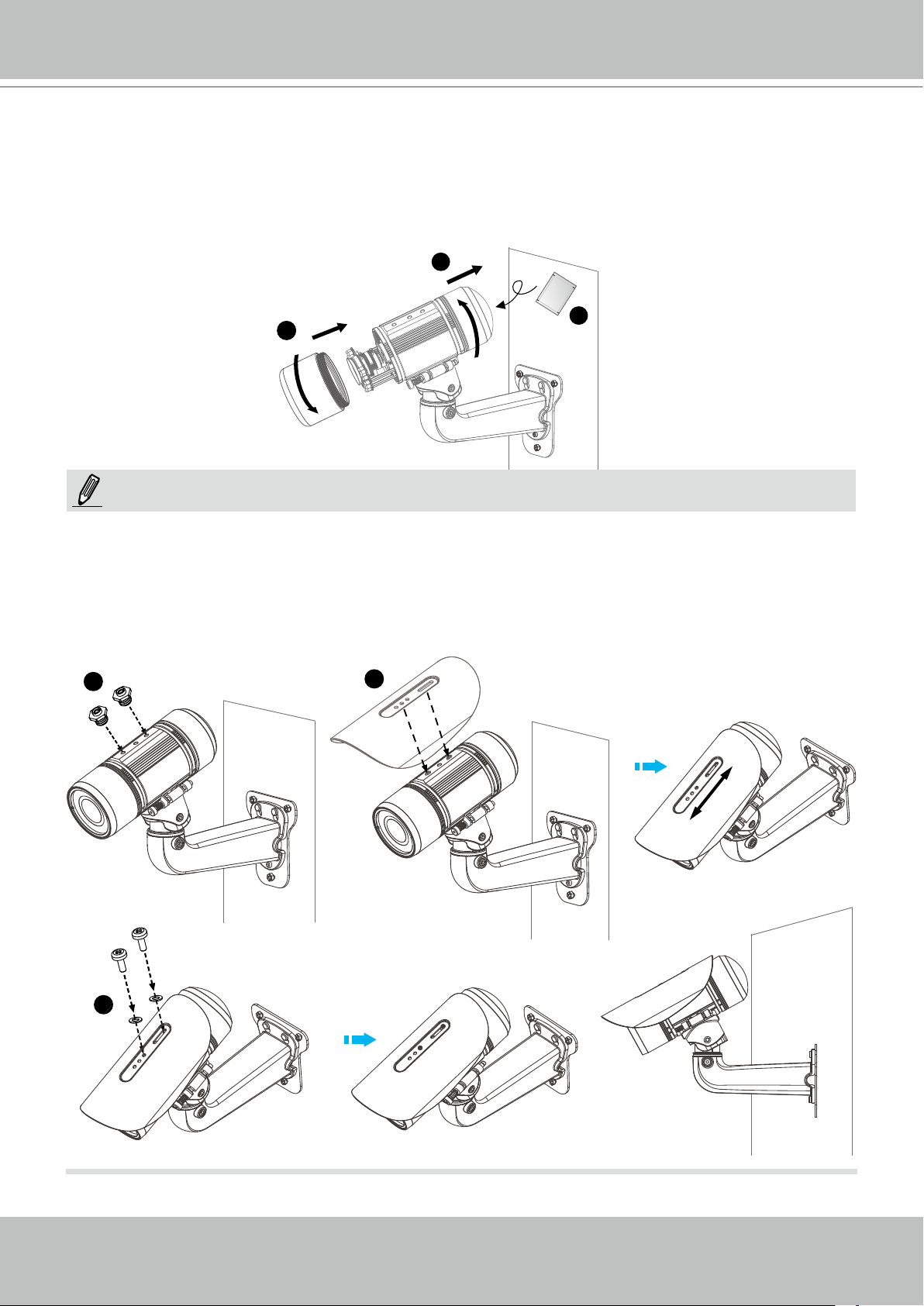
5. Tighten the lens cover.
6. Open the back cover.
7. Tear down the aluminum foil vacuum bag and take out the silica gel. Attach the silica gel to
the inner side of the back cover, then tighten the back cover. (Please replace the silica gel
desiccant with a new one if you open the back cover after installation.)
6
5
7
NOTE:
If you want to use the supplied sun shield for outdoor environments, please follow the steps
below to install:
1. Tighten the supplied two coupler screws.
2. Attach the supplied sun shield to the Network Camera and slide it to the desired position.
3. Fix the sun shield with the supplied two screws.
1
2
3
User's Manual - 17
VIVOTEK
Accessories
VIVOTEK also provides other accessories for versatile applications as the following illustrations.
Please visit VIVOTEK's ofcial website for more purchase information.
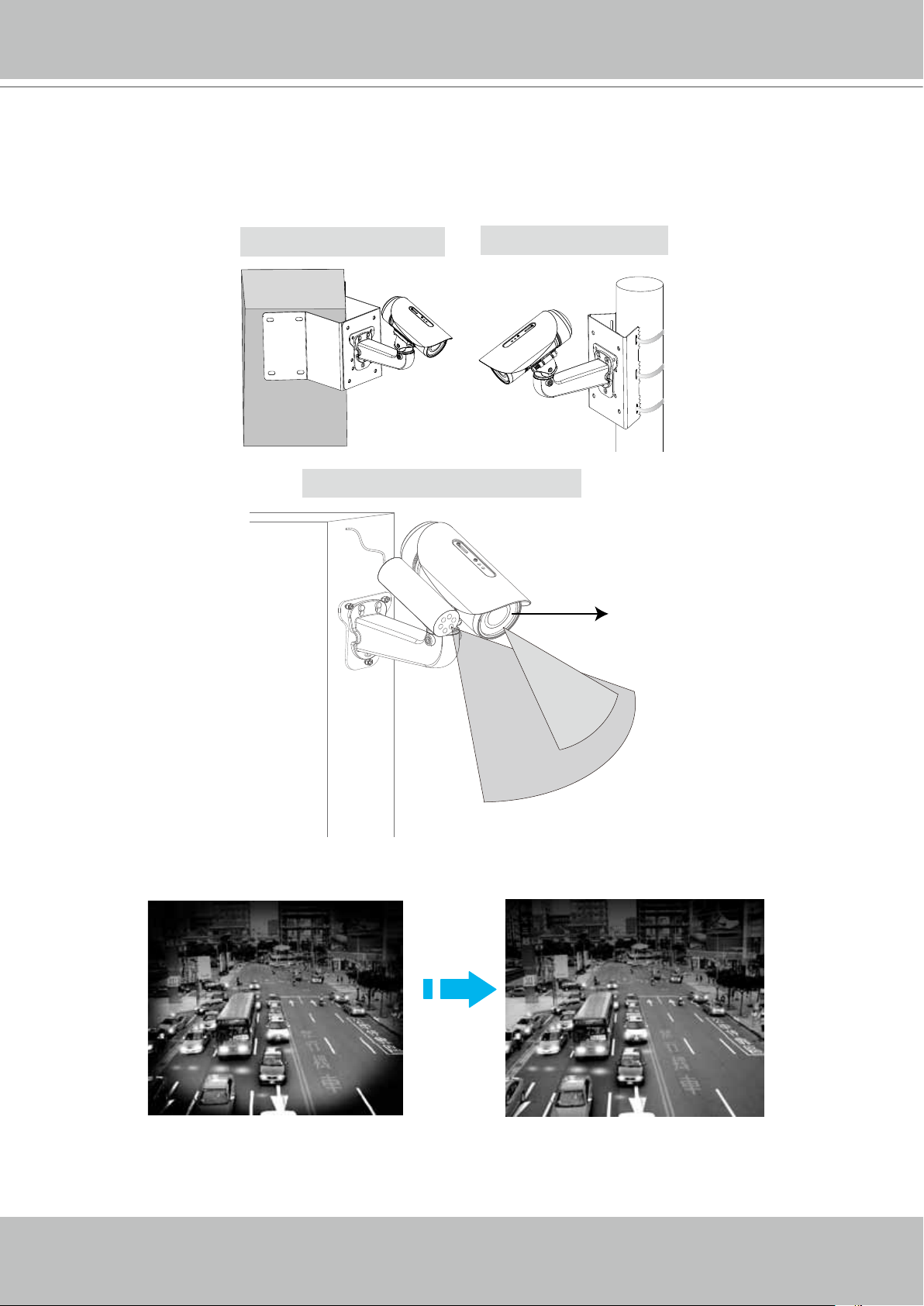
Corner Mount Bracket
IR illuminator (distance 30m, 60°)
Pole Mount Bracket
60°
35°
Built-in 24 LED units
(distance 25m, 35°)
The 30m, 60° IR illuminator extends the coverage of the Network Camera and reduces the halo
effect around captured images.
18 - User's Manual
VIVOTEK
Accessing the Network Camera
This chapter explains how to access the Network Camera through web browsers, RTSP players,
3GPP-compatible mobile devices, and VIVOTEK recording software.
Using Web Browsers
Use Installation Wizard 2 (IW2) to access to the Network Cameras on the LAN.
If your network environment is not a LAN, follow these steps to access the Netwotk Camera:
1. Launch your web browser (ex. Microsoft
2. Enter the IP address of the Network Camera in the address eld. Press Enter.
3. The live video will be displayed in your web browser.
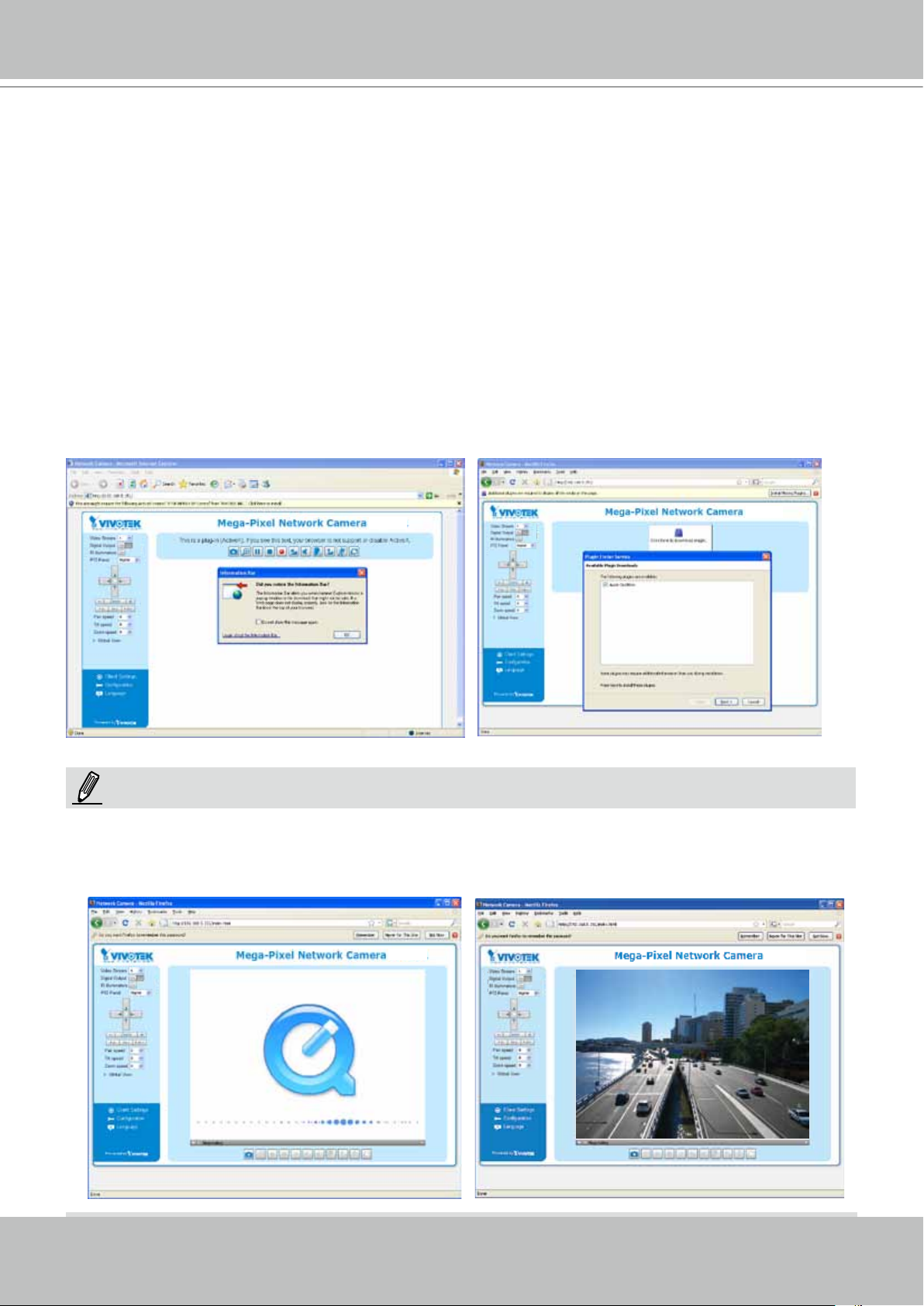
4. If it is the rst time installing the VIVOTEK network camera, an information bar will pop up as
shown below. Follow the instructions to install the required plug-in on your computer.
®
Internet Explorer, Mozilla Firefox, or Netscape).
NOTE:
► For Mozilla Firefox or Netscape users, your browser will use Quick Time to stream the live
video. If you do not have Quick Time on your computer, please download it rst, then launch
the web browser.
User's Manual - 19
VIVOTEK
► By default, the Network Camera is not password-protected. To prevent unauthorized access,
it is highly recommended to set a password for the Network Camera.
For more information about how to enable password protection, please refer to Security on
page 34.
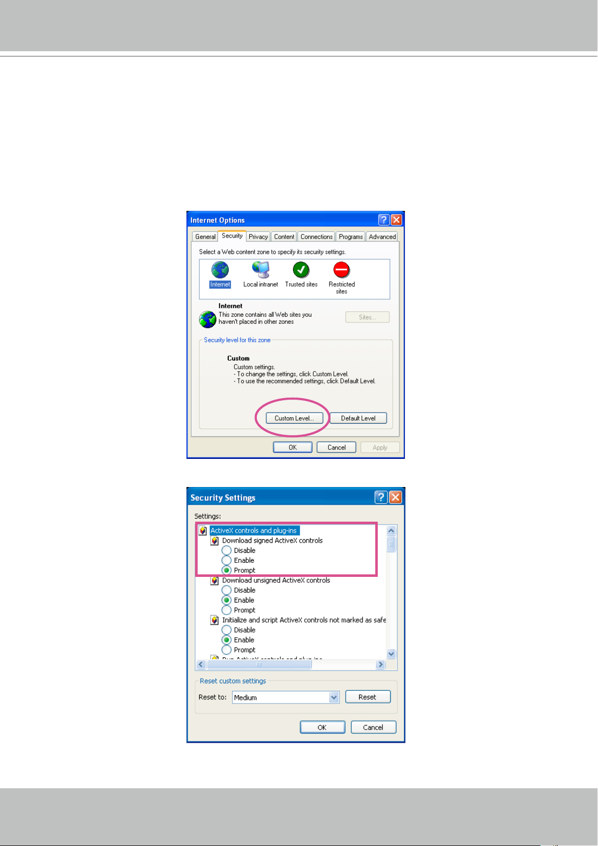
► If you see a dialog box indicating that your security settings prohibit running ActiveX
®
Controls, please enable the ActiveX
Controls for your browser.
®
1. Choose Tools > Internet Options > Security > Custom Level.
2. Look for Download signed ActiveX
®
controls; select Enable or Prompt. Click OK.
3. Refresh your web browser, then install the Active X
complete installation.
®
control. Follow the instructions to
20 - User's Manual

IMPORTANT:
Currently the Network Camera utilizes 32-bit ActiveX plugin. You CAN NOT open a
•
management/view session with the camera using a 64-bit IE browser.
If you encounter this problem, try execute the Iexplore.exe program from C:\
•
Windows\SysWOW64. A 32-bit version of IE browser will be installed.
On Windows 7, the 32-bit explorer browser can be accessed from here:
•
C:\Program Files (x86)\Internet Explorer\iexplore.exe
VIVOTEK
User's Manual - 21
VIVOTEK
Using RTSP Players
To view the MPEG-4 streaming media using RTSP players, you can use one of the following
players that support RTSP streaming.
Quick Time Player
VLC Media Player
mpegable Player
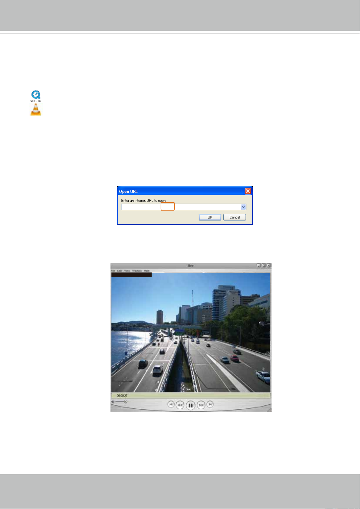
1. Launch the RTSP player.
pvPlayer
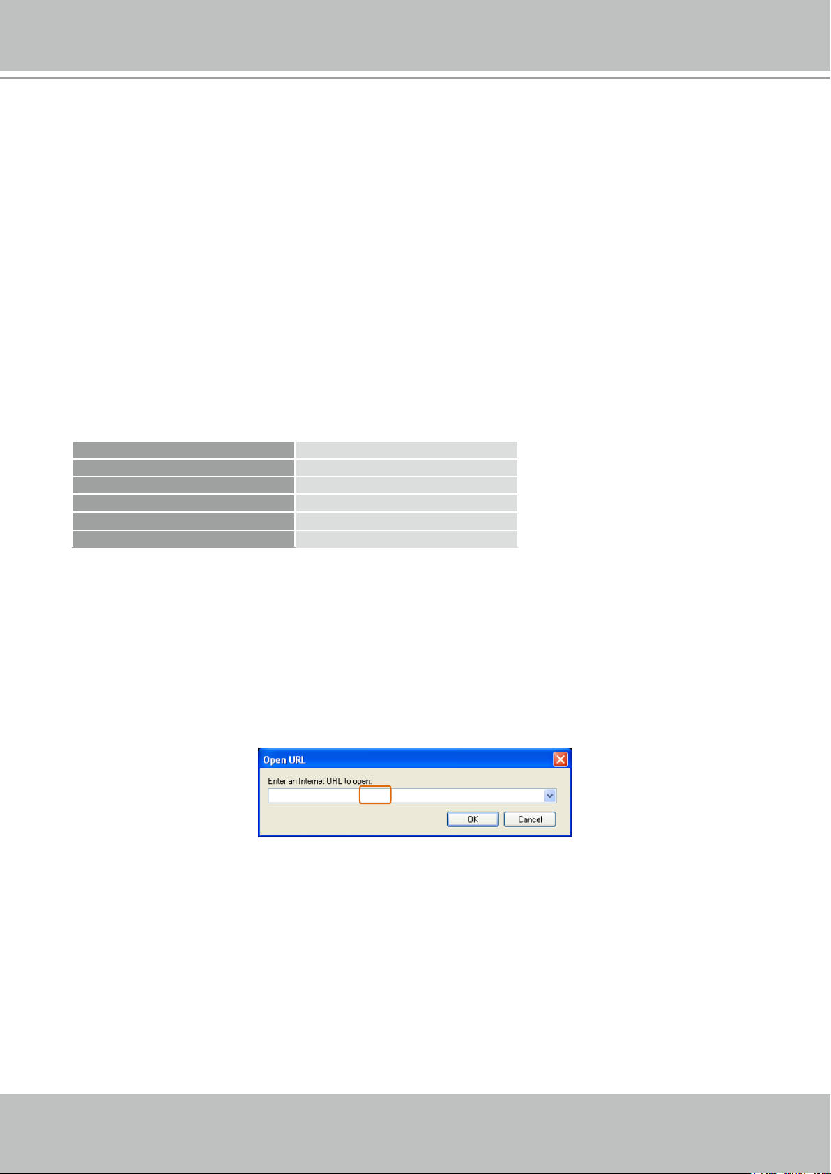
2. Choose File > Open URL. A URL dialog box will pop up.
3. The address format is rtsp://<ip address>:<rtsp port>/<RTSP streaming access name for
stream1/stream2/stream3>
As most ISPs and players only allow RTSP streaming through port number 554, please set the
RTSP port to 554. For more information, please refer to RTSP Streaming on page 54.
For example:
rtsp://192.168.5.151:554/live.sdp
4. The live video will be displayed in your player.
For more information on how to configure the RTSP access name, please refer to RTSP
Streaming on page 54 for details.
Video 16:38:01 2008/01/03
22 - User's Manual
VIVOTEK
Using 3GPP-compatible Mobile Devices
To view the streaming media through 3GPP-compatible mobile devices, make sure the Network
Camera can be accessed over the Internet. For more information on how to set up the Network
Camera over the Internet, please refer to Setup the Network Camera over the Internet on page
12.
To utilize this feature, please check the following settings on your Network Camera:
1. Because most players on 3GPP mobile phones do not support RTSP authentication, make
sure the authentication mode of RTSP streaming is set to disable.
For more information, please refer to RTSP Streaming on page 54.
2. As the the bandwidth on 3G networks is limited, you will not be able to use a large video size.
Please set the video and audio streaming parameters as listed below.
For more information, please refer to Viewing Window on page 67.
Video Mode MPEG-4
Frame size 176 x 144
Maximum frame rate 5 fps
Intra frame period 1S
Video quality (Constant bit rate) 40kbps
Audio type (GSM-AMR) 12.2kbps
3. As most ISPs and players only allow RTSP streaming through port number 554, please set
the RTSP port to 554. For more information, please refer to RTSP Streaming on page 54.
4. Launch the player on the 3GPP-compatible mobile devices (ex. Real Player).
5. Type the following URL commands into the player.
The address format is rtsp://<public ip address of your camera>:<rtsp port>/<RTSP streaming
access name for stream 3>.
For example:
rtsp://192.168.5.151:554/live.sdp
User's Manual - 23
VIVOTEK
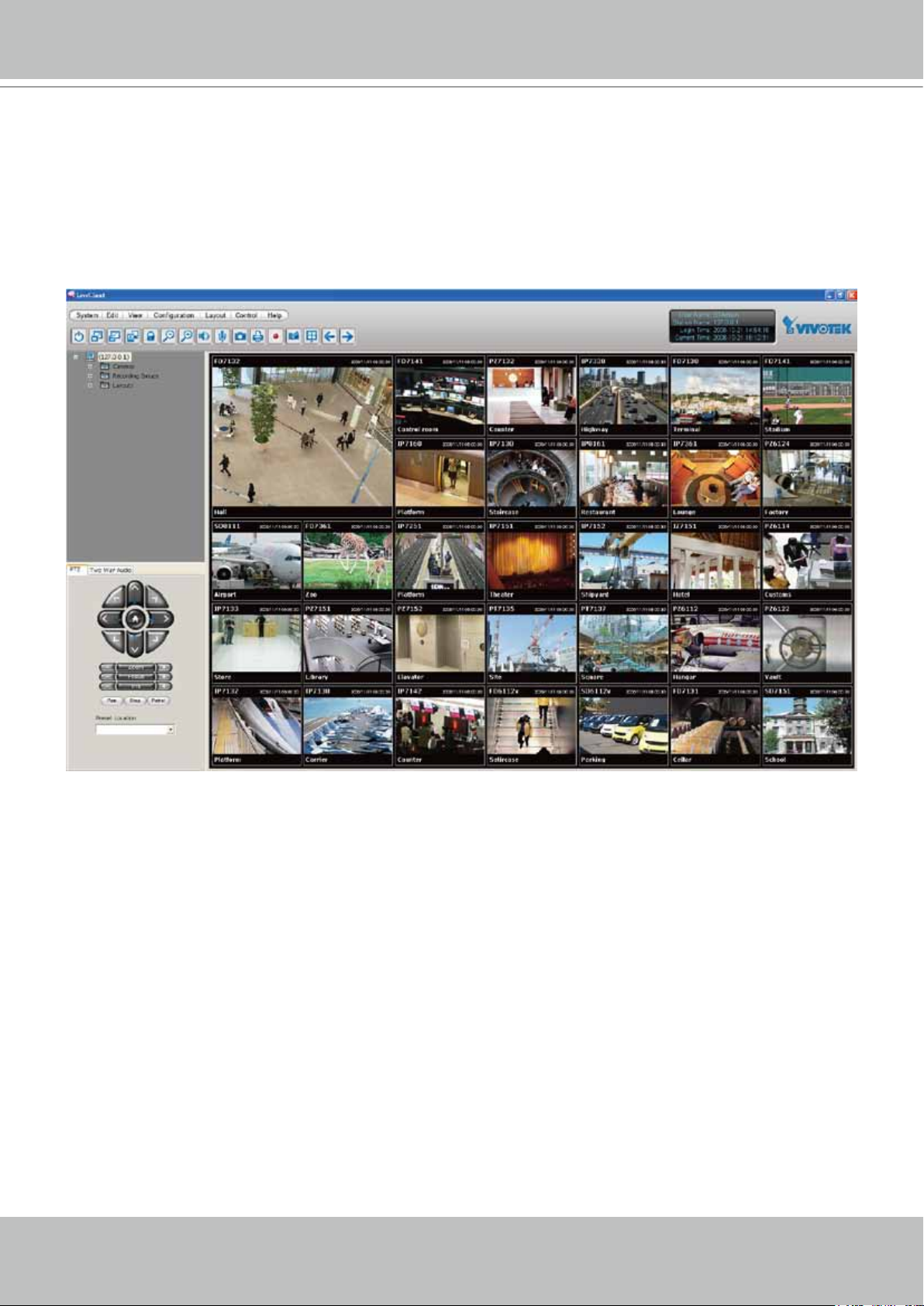
Using VIVOTEK Recording Software
The product software CD also contains an ST7501 recording software, allowing simultaneous
monitoring and video recording for multiple Network Cameras. Please install the recording
software; then launch the program to add the Network Camera to the Channel list. For detailed
information about how to use the recording software, please refer to the user’s manual of the
software or download it from http://www.vivotek.com.
24 - User's Manual
VIVOTEK
Main Page
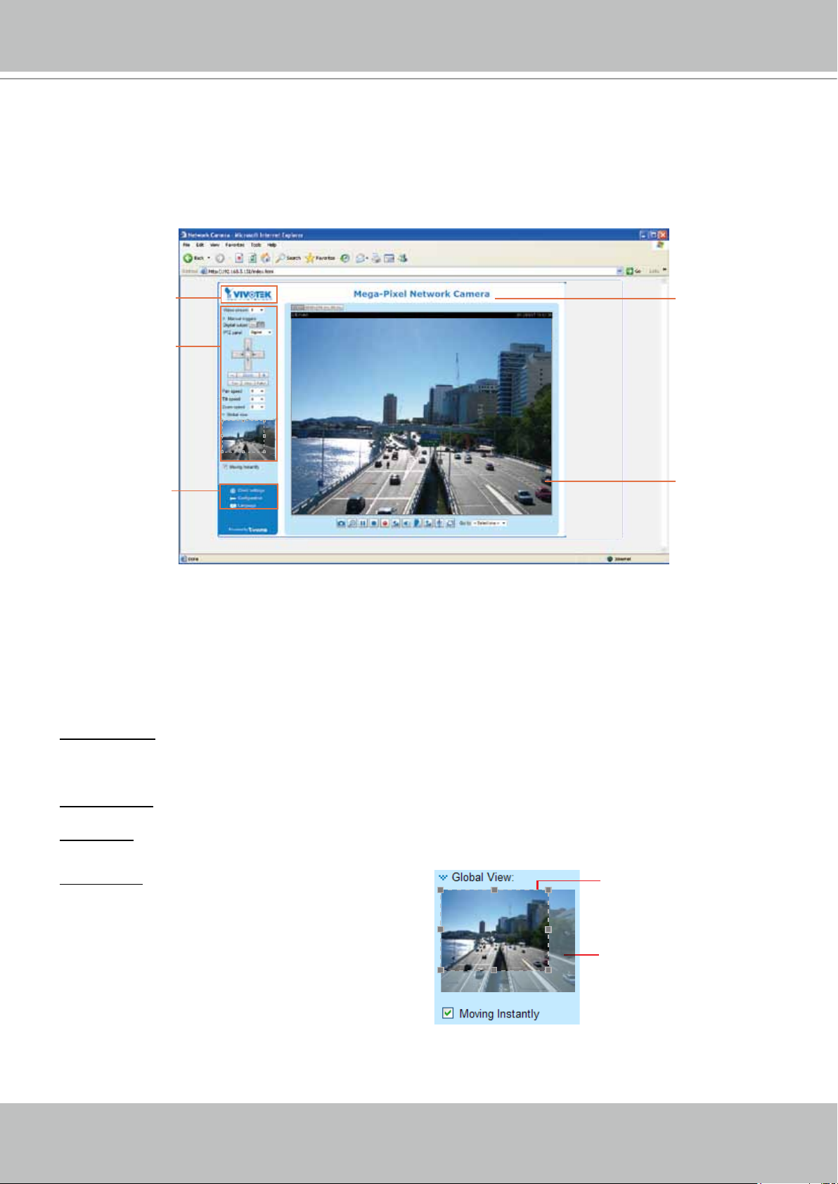
This chapter explains the layout of the main page. It is composed of the following sections:
VIVOTEK INC. Logo, Host Name, Camera Control Area, Configuration Area, Menu, and Live
Video Window.
VIVOTEK INC. Logo
Camera Control Area
Configuration Area
Host Name
Live View Window
VIVOTEK INC. Logo
Click this logo to visit the VIVOTEK website.
Host Name
The host name can be customized to t your needs. For more information, please refer to System on page
32.
Camera Control Area
Video Stream: This Network Cmera supports multiple streams (stream 1 ~ 3) simultaneously. You can
select either one for live viewing. For more information about multiple streams, please refer to page 67
for detailed information.
Digital Output: Click to turn the digital output device on or off.
PTZ Panel: This Network Camera supports both “digital“ (e-PTZ) and “mechanical“ pan/tilt/zoom control.
Please refer to Camera Control on page 78 for detailed information.
Global View: Click on this item to display the Global
View window. The Global View window contains a full
view image (the largest frame size of the captured
video) and a oating frame (the viewing region of the
curruent video stream). The floating frame allows
users to control the e-PTZ function (Electronic
Pan/Tilt/Zoom). For more information about e-PTZ
operation, please refer to E-PTZ Operation on page
83. For more information about how to set up the
viewing region of the current video stream, please
refer to Viewing Windows on page 67.
The viewing region of
the curruent video
stream
The largest frame size
User's Manual - 25
VIVOTEK
Conguration Area
Client Settings: Click this button to access the client setting page. For more information, please refer to
Client Settings on page 29.
Conguration: Click this button to access the conguration page of the Network Camera. It is suggested
that a password be applied to the Network Camera so that only the administrator can configure the
Network Camera. For more information, please refer to Conguration on page 31.
Language: Click this button to choose a language for the user interface. Language options are available
in: English, Deutsch, Español, Français, Italiano,
日本語
, Português,
簡体中文
, and
繁體中文
.
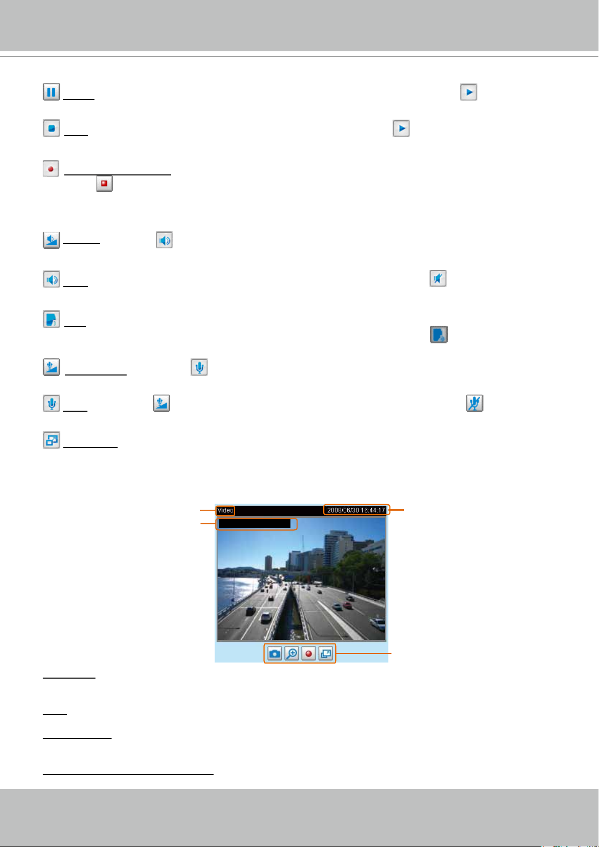
Live Video Window
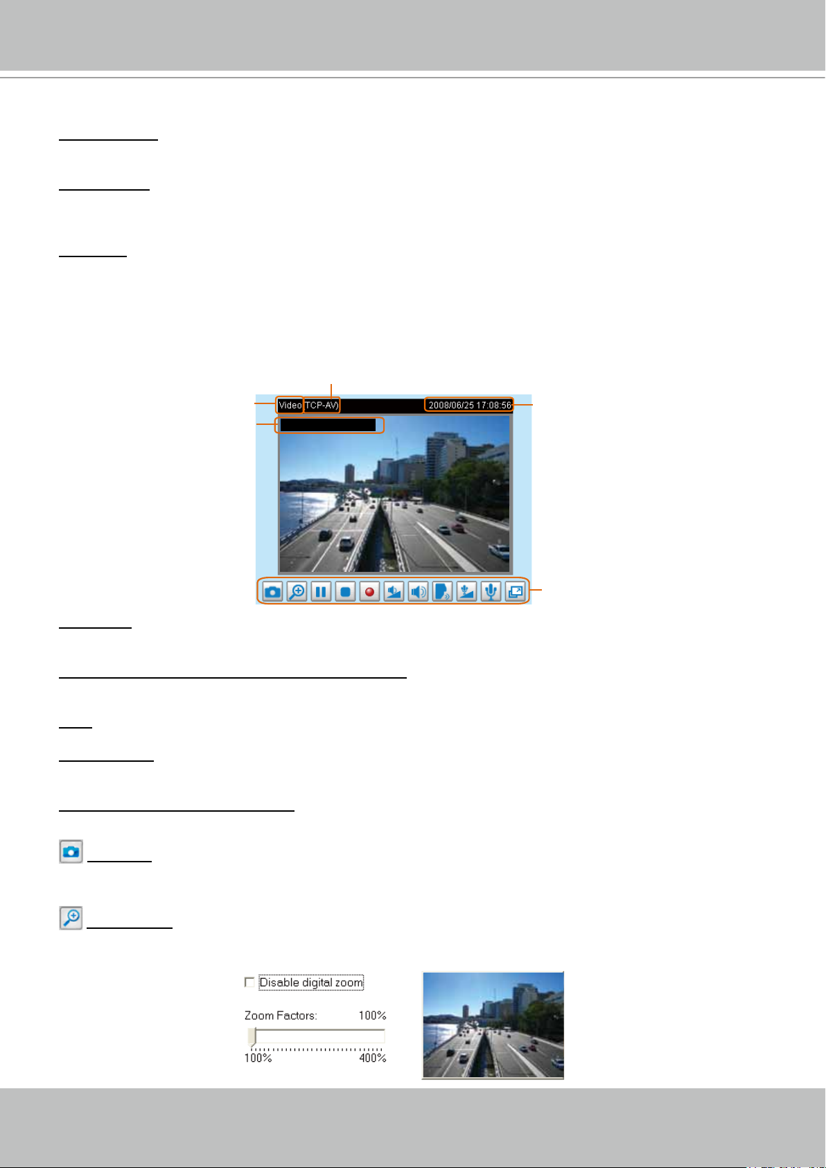
■ The following window is displayed when the video mode is set to MPEG-4 or H.264:
H.264 & MPEG-4 Protocol and Media Options
Video Title
Title and Time
Video 17:08:56 2008/06/25
Time
Video and Audio Control Buttons
Video Title: The video title can be congured. For more information, please refer to Video Settings on
page 61.
H.264 and MPEG-4 Protocol and Media Options: The transmission protocol and media options for
MPEG-4 video streaming. For further conguration, please refer to Client Settings on page 29.
Time: Display the current time. For further conguration, please refer to Video Settings on page 61.
Title and Time: The video title and time can be stamped on the streaming video. For further conguration,
please refer to Video Settings on page 61.
Video and Audio Control Buttons: Depending on the Network Camera model and Network Camera
conguration, some buttons may not be available.
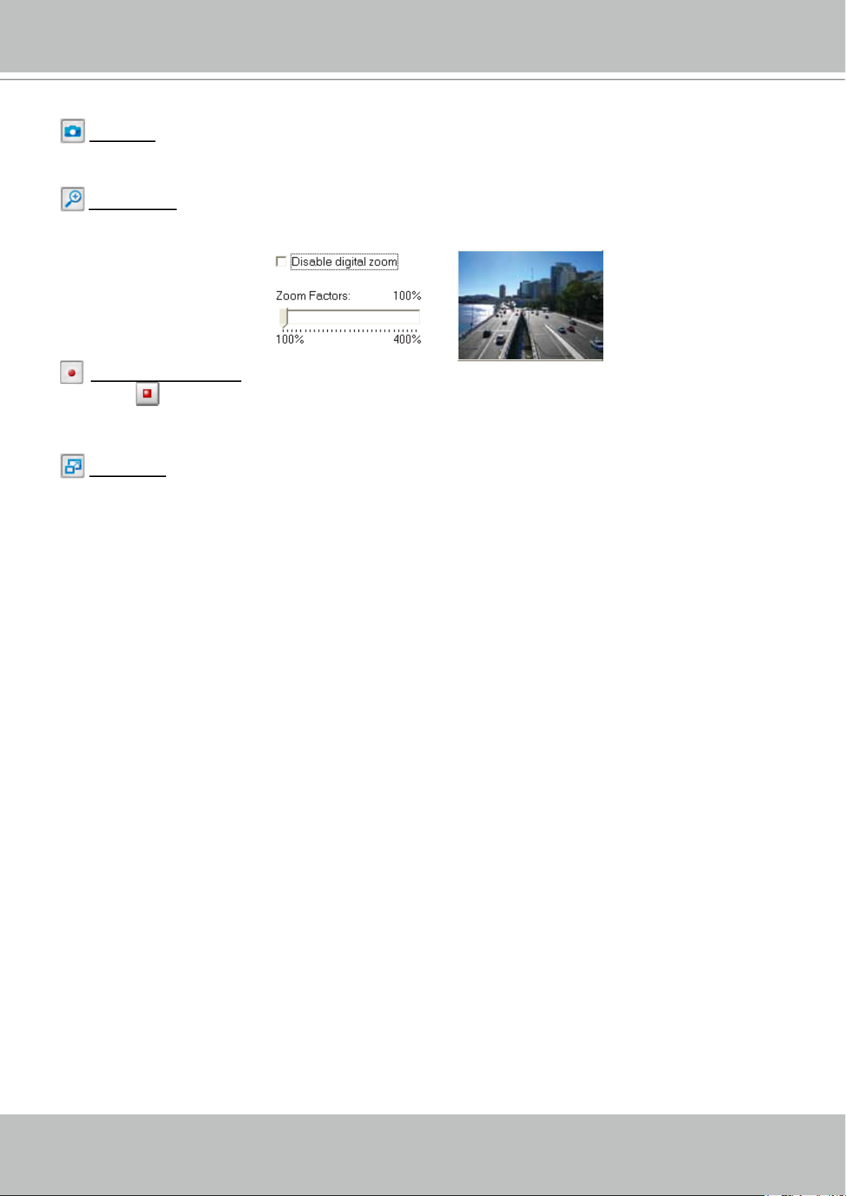
Snapshot: Click this button to capture and save still images. The captured images will be displayed
in a pop-up window. Right-click the image and choose Save Picture As to save it in JPEG (*.jpg) or BMP
(*.bmp) format.
Digital Zoom: Click and uncheck “Disable digital zoom” to enable the zoom operation. The navigation
screen indicates the part of the image being magnied. To control the zoom level, drag the slider bar. To
move to a different area you want to magnify, drag the navigation screen.
26 - User's Manual
VIVOTEK
Pause: Pause the transmission of the streaming media. The button becomes the Resume button
after clicking the Pause button.
Stop: Stop the transmission of the streaming media. Click the Resume button to continue
transmission.
Start MP4 Recording: Click this button to record video clips in MP4 file format to your computer.
Press the
Stop MP4 Recording button to end recording. When you exit the web browser, video
recording stops accordingly. To specify the storage destination and le name, please refer to MP4 Saving
Options on page 30 for details.
Volume: When the Mute function is not activated, move the slider bar to adjust the volume on the
local computer.
Mute: Turn off the volume on the local computer. The button becomes the Audio On button after
clicking the Mute button.
Talk: Click this button to talk to people around the Network Camera. Audio will project from
the external speaker connected to the Network Camera. Click this button
again to end talking
transmission.
Mic Volume: When the Mute function is not activated, move the slider bar to adjust the
microphone volume on the local computer.
Mute: Turn off the Mic volume on the local computer. The button becomes the Mic On button
after clicking the Mute button.
Full Screen: Click this button to switch to full screen mode. Press the “Esc” key to switch back to normal
mode.
■ The following window is displayed when the video mode is set to MJPEG:
Video Title
Title and Time
Video 13:44:17 2008/06/30
Time
Video Control Buttons
Video Title: The video title can be congured. For more information, please refer to Video Settings on
page 61.
Time: Display the current time. For more information, please refer to
Video Settings on page 61.
Title and Time: Video title and time can be stamped on the streaming video. For more information, please
refer to
Video Settings on page 61.
Video and Audio Control Buttons: Depending on the Network Camera model and Network Camera
conguration, some buttons may not be available.
User's Manual - 27
VIVOTEK
Snapshot: Click this button to capture and save still images. The captured images will be displayed
in a pop-up window. Right-click the image and choose Save Picture As to save it in JPEG (*.jpg) or BMP
(*.bmp) format.
Digital Zoom: Click and uncheck “Disable digital zoom” to enable the zoom operation. The navigation
screen indicates the part of the image being magnied. To control the zoom level, drag the slider bar. To
move to a different area you want to magnify, drag the navigation screen.
Start MP4 Recording: Click this button to record video clips in MP4 file format to your computer.
Press the
Stop MP4 Recording button to end recording. When you exit the web browser, video
recording stops accordingly. To specify the storage destination and le name, please refer to MP4 Saving
Options on page 30 for details.
Full Screen: Click this button to switch to full screen mode. Press the “Esc” key to switch back to normal
mode.
28 - User's Manual
VIVOTEK
Client Settings
This chapter explains how to select the stream transmission mode and saving options on the
local computer. When completed with the settings on this page, click Save on the page bottom
to enable the settings.
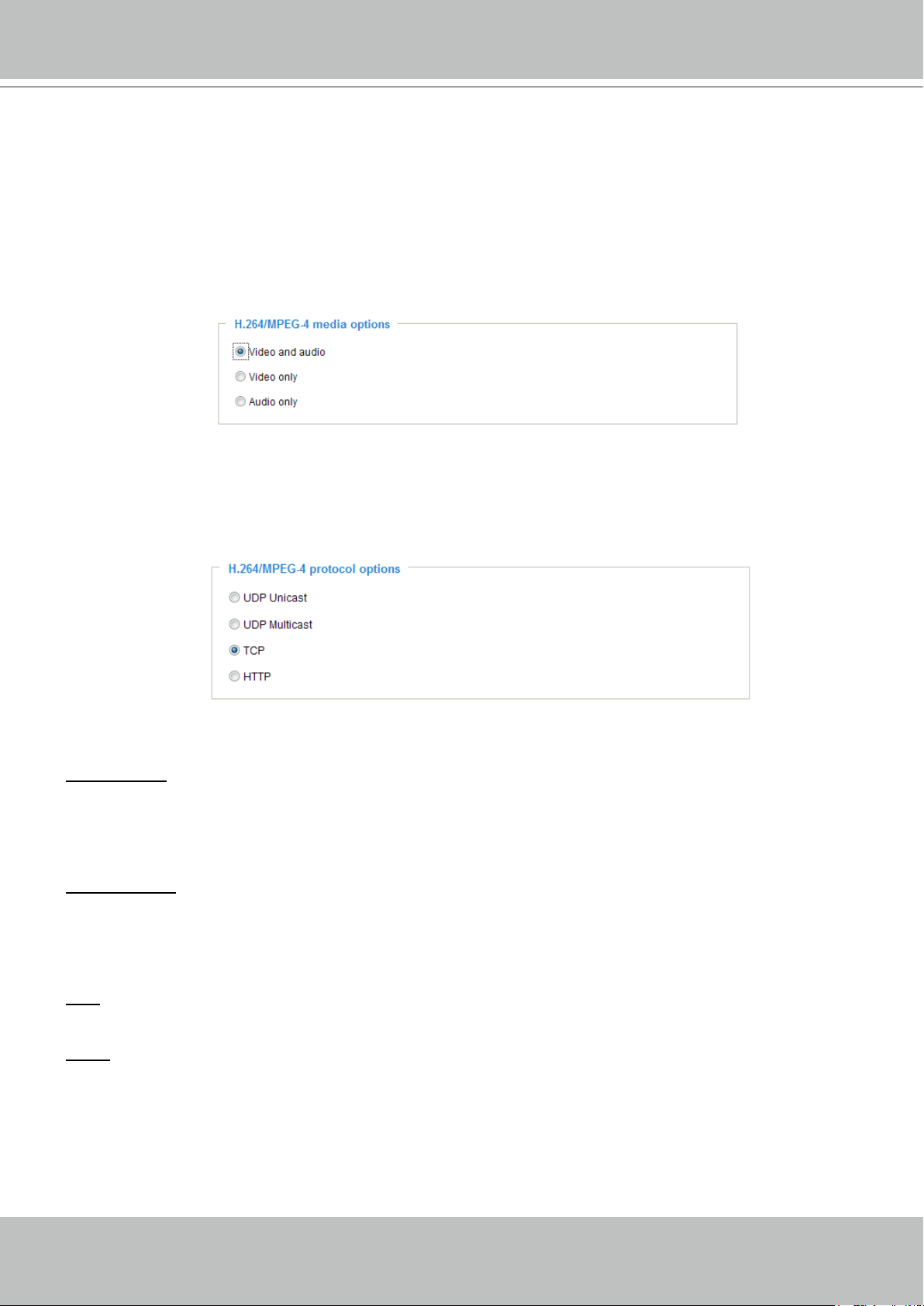
H.264/MPEG-4 Media Options
Select to stream video or audio data or both. This is enabled only when the video mode is set to H.264 or
MPEG-4.
H.264/MPEG-4 Protocol Options
Depending on your network environment, there are four transmission modes of H.264/MPEG-4
streaming:
UDP unicast: This protocol allows for more real-time audio and video streams. However, network
packets may be lost due to network burst trafc and images may be broken. Activate UDP connection
when occasions require time-sensitive responses and the video quality is less important. Note that each
unicast client connecting to the server takes up additional bandwidth and the Network Camera allows up
to ten simultaneous accesses.
UDP multicast: This protocol allows multicast-enabled routers to forward network packets to all clients
requesting streaming media. This helps to reduce the network transmission load of the Network Camera
while serving multiple clients at the same time. Note that to utilize this feature, the Network Camera must
be configured to enable multicast streaming at the same time. For more information, please refer to
RTSP Streaming on page 54.
TCP: This protocol guarantees the complete delivery of streaming data and thus provides better video
quality. The downside of this protocol is that its real-time effect is not as good as that of the UDP protocol.
HTTP: This protocol allows the same quality as TCP protocol without needing to open specic ports for
streaming under some network environments. Users inside a firewall can utilize this protocol to allow
streaming data through.
User's Manual - 29
VIVOTEK
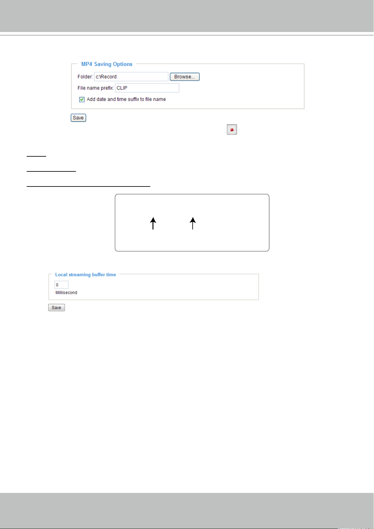
MP4 Saving Options
Users can record live video as they are watching it by clicking Start MP4 Recording on the main
page. Here, you can specify the storage destination and le name.
Folder: Specify a storage destination for the recorded video les.
File name prex: Enter the text that will be appended to the front of the video le name.
Add date and time sufx to the le name: Select this option to append the date and time to the end of the
le name.
CLIP_20080108-180853
File name prefix
Date and time suffix
The format is: YYYYMMDD_HHMMSS
Local Streaming Buffer Time
Due to unsteady bandwidth flow, live streaming may lag and not be very smoothly. If you enable this
option, the live streaming will be stored on the camera’s buffer area for a few seconds before being
played on the live viewing window. This helps produce a smooth live streaming. If you enter a value of
3000 milliseconds, the streaming will delay for 3 seconds.
30 - User's Manual
 Loading...