

Bullet
IP8337H-C
Network Camera
User’s Manual
Outdoor • Day & Night • Weather-proof • Cable Management
Rev. 1.0

VIVOTEK
Table of Contents
Overview
Revision History ...................................................................................................................................... 4
Read Before Use ..................................................................................................................................... 5
Package Contents ................................................................................................................................... 5
Symbols and Statements in this Document ............................................................................................. 5
Hardware Installation ............................................................................................................................... 7
Network Deployment ............................................................................................................................. 12
Software Installation .............................................................................................................................. 14
Ready to Use ......................................................................................................................................... 15
Secure the Shooting Angle .................................................................................................................... 16
Accessing the Network Camera
Using Web Browsers ............................................................................................................................. 17
Using RTSP Players .............................................................................................................................. 20
Using 3GPP-compatible Mobile Devices ............................................................................................... 21
Using VIVOTEK Recording Software .................................................................................................... 22
Main Page
Client Settings
Conguration
System > General settings .................................................................................................................... 33
System > Homepage layout ................................................................................................................. 35
System > Logs ...................................................................................................................................... 38
System > Parameters ........................................................................................................................... 39
System > Maintenance .......................................................................................................................... 40
Media > Image .................................................................................................................................... 44
Media > Video ....................................................................................................................................... 52
Media > Video ....................................................................................................................................... 53
Network > General settings ................................................................................................................... 57
Network > Streaming protocols ........................................................................................................... 64
Network > SNMP (Simple Network Management Protocol).................................................................. 73
Security > User accounts ...................................................................................................................... 74
Security > HTTPS (Hypertext Transfer Protocol over SSL) ........................................................75
Security > Access List ......................................................................................................................... 82
PTZ > PTZ settings ............................................................................................................................... 87
Event > Event settings........................................................................................................................... 91
Applications > Motion detection........................................................................................................... 104
Applications > Digital input .................................................................................................................. 107
Applications > Tampering detection ....................................................................................................107
Applications > VADP (VIVOTEK Application Development Platform ...................................................108
Recording > Recording settings ......................................................................................................... 11 0
Local storage > SD card management ................................................................................................ 115
Local storage > Content management ................................................................................................ 11 6
Appendix
URL Commands for the Network Camera ........................................................................................... 119
Technical Specications ...................................................................................................................... 201
.....................................................................................................................................................
............................................................................................................
.................................................................................................................................................
..........................................................................................................................................
............................................................................................................................................
................................................................................................................................................
4
17
23
28
32
119
2 - User's Manual

VIVOTEK
Technology License Notice ....................................................................................................................... 202
Electromagnetic Compatibility (EMC) .......................................................................................................203
User's Manual - 3

VIVOTEK
Overview
VIVOTEK IP8337H-C is a best-in-class, bullet-style network camera designed for diverse
outdoor applications. It features an HD WDR CMOS sensor to cope with challenging lighting
conditions. The WDR feature allows the camera to capture both the dark and bright parts of an
image and combines the differences to generate a highly realistic image representative of the
original scene, enabling it to provide video quality close to the capabilities of the human eye.
This function enables the IP8337H-C to be widely applicable in high contrast environments such
as lobby entrances, parking lots, ATMs, loading areas, and much more.
In order to adapt to constantly changing outdoor lighting conditions, the IP8337H-C features a
removable IR-cut lter as well as IR illuminators effective up to 20M for superior image quality
around the clock. For protection against harsh outdoor environments, the camera is encased
in an IP66-rated housing to withstand dust and rain. The IP8337H-C further strengthens the
robustness of the camera by protecting the cable within the bracket.
The IP8337H-C supports the industry-standard H.264 compression technology, drastically
reducing file sizes and conserving valuable network bandwidth. With H.264, and MJPEG
compatibility both included, the dual streams can be simultaneously transmitted in any of these
formats at different resolutions, frame rates, and image qualities for versatile platforms. Thereby
it further optimizes bandwidth and storage efciency.
Incorporating a number of advanced features standard for VIVOTEK cameras, including tamper
detection, 802.3af compliant PoE, MicroSD/SDHC card slot, and VIVOTEK’s 32-channel
recording software, the IP8337H-C is the ideal solution for your outdoor surveillance needs.
Revision History
■ Rev. 1.0: Initial release
■ Rev. 1.1: The later revision of rmware, 0101a, supports the 3D Noise Reduction
conguration.
4 - User's Manual
VIVOTEK
i
Read Before Use
The use of surveillance devices may be prohibited by law in your country. The Network Camera
is not only a high-performance web-ready camera but can also be part of a exible surveillance
system. It is the user’s responsibility to ensure that the operation of such devices is legal before
installing this unit for its intended use.
It is important to first verify that all contents received are complete according to the Package
Contents listed below. Take note of the warnings in the Quick Installation Guide before the Network
Camera is installed; then carefully read and follow the instructions in the Installation chapter to
avoid damage due to faulty assembly and installation. This also ensures the product is used
properly as intended.
The Network Camera is a network device and its use should be straightforward for those who
have basic networking knowledge. It is designed for various applications including video sharing,
general security/surveillance, etc. The Configuration chapter suggests ways to best utilize the
Network Camera and ensure proper operations. For creative and professional developers, the URL
Commands of the Network Camera section serves as a helpful reference to customizing existing
homepages or integrating with the current web server.
Package Contents
■ IP8337H-C
■ Ball swivel mount bracket
■ L-type Hex key wrench, dessicant bag, screws, rubber seal
■ Software CD
■ Warranty Card
■ Quick Installation Guide & alignment sticker
Symbols and Statements in this Document
INFORMATION: provides important messages or advices that might help prevent
inconvenient or problem situations.
NOTE: Notices provide guidance or advices that are related to the functional integrity of
the machine.
Tips: Tips are useful information that helps enhance or facilitae an installation, function,
or process.
WARNING! or IMPORTANT!: These statements indicate situations that can be
dangerous or hazardous to the machine or you.
Electrical Hazard: This statement appears when high voltage electrical hazards might
occur to an operator.
User's Manual - 5
VIVOTEK
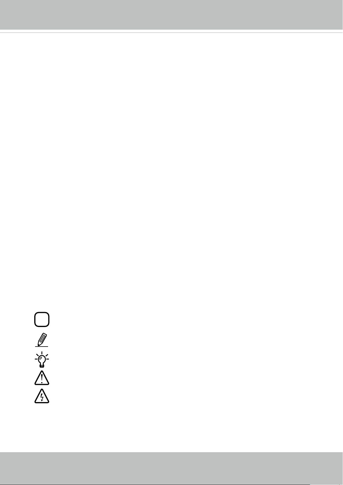
Front Panel
Rear Panel
Lens
IR LEDs
Reset Button
General I/O Terminal
Block
MicroSD/SDHC
Card Slot
Ethernet 10/100 RJ45 Plug
6 - User's Manual
VIVOTEK
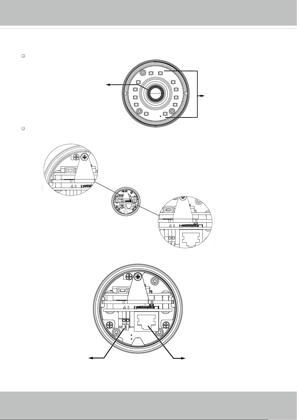
Hardware Installation
If you prefer installing a MicroSD card as onboard storage:
1. Loosen the waterproof connector, and then remove the rubber seal, and the waterproof
connector.
2. Loosen and open the rear cover.
3. Install a MicroSD/SDHC card.
4. Tear down the aluminum foil vacuum bag and take out the dessicant bag. Attach the
supplied dessicant bag to the inner side of the Network Camera. (Please replace the
dessicant bag with a new one every time you open the rear cover.)
5. Connect an Ethernet cable and DI lines to the camera, and pass them through the
rubber seal.
icro
M
SD
2
1
3
5
IMPORTANT:
The diameters of the cable holes on the rubber seal
are shown on the right. Please properly install the
waterproof cable gland and cables through it to obtain
IP66 waterproof functionality.
All units are in millimeters. The cable range for the
Ethernet cable is 6.4 to 4.3mm, 1.6mm for DI lines.
4
Silica gel
User's Manual - 7

VIVOTEK
General I/O Terminal Block
This Network Camera provides two digital input pins that can be connected to external sensor
devices. The pin denitions are described below.
DI- DI+
DI/DO Diagram
Please refer to the following illustration for the connection method.
+12V
PIN 2
Digital input
PIN 1
Ground
8 - User's Manual
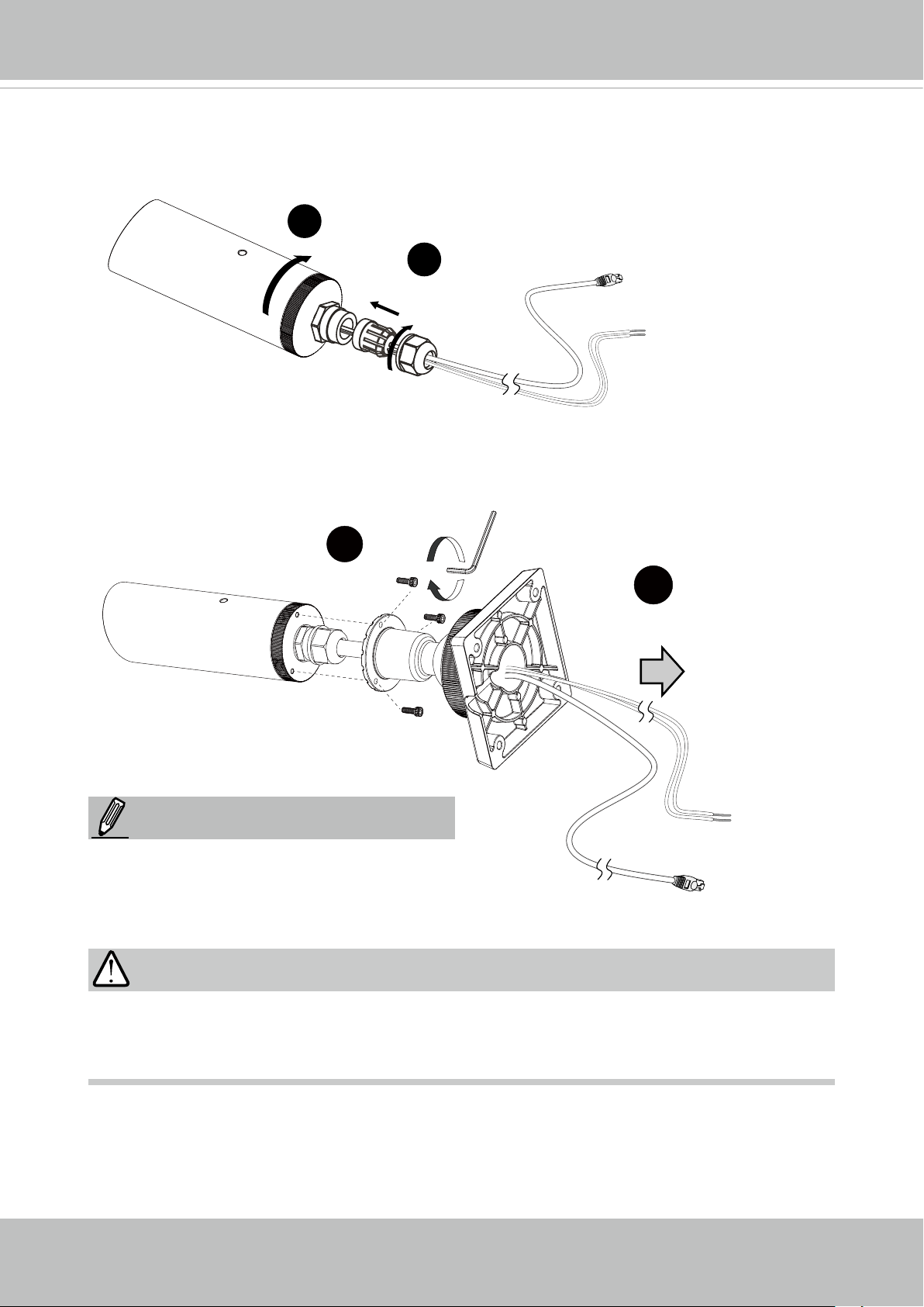
6. Install and tighten the camera's rear cover.
7. Tighten the rubber seal, seal clamp, and cap nut of the waterproof connector.
6
7
8. Pass the cables through the center of the ball swivel mount bracket, one at a time.
9. Fasten the bracket to the camera using 3 hex socket screws.
VIVOTEK
9
NOTE:
The camera weighs up to 1.28 kgs. Make
sure the mounting surface can support this
camera.
IMPORTANT:
8
Whenever you want to open the camera canister, loosen the waterproof cable gland before
you loosen the rear cover. Otherwise, you can damage the cables attached to the inside of
the camera.
User's Manual - 9
VIVOTEK
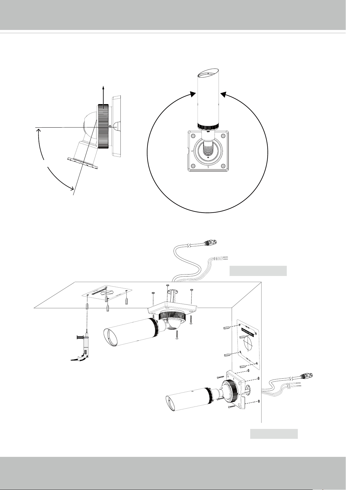
10. Loosen the fastening ring on the mount bracket, and aim the camera at the area of
your interest. When done, tighten the fastening ring.
Fastening ring
75º Tilt
360º Pan
11. Secure the Network Camera to a wall or ceiling.
Ceiling Mount
10 - User's Manual
Wall Mount
VIVOTEK
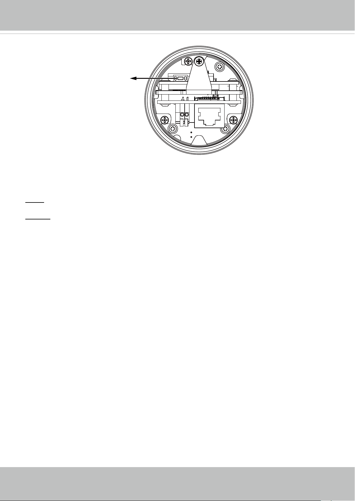
Hardware Reset
Reset Button
The reset button is used to reset the system or restore the factory default settings. Sometimes
resetting the system can return the camera to normal operation. If the system problems remain
after reset, restore the factory settings and install again.
Reset: Press the recessed reset button. Wait for the Network Camera to reboot.
Restore: Press and hold the reset button until the status LED rapidly blinks. Note that all settings
will be restored to factory default. Upon successful restore, the status LED will blink green and
red during normal operation.
Micro SD/SDHC Card Capacity
This network camera is compliant with Micro SD/SDHC 16GB / 8GB / 32GB and other
preceding standard SD cards.
User's Manual - 11
VIVOTEK
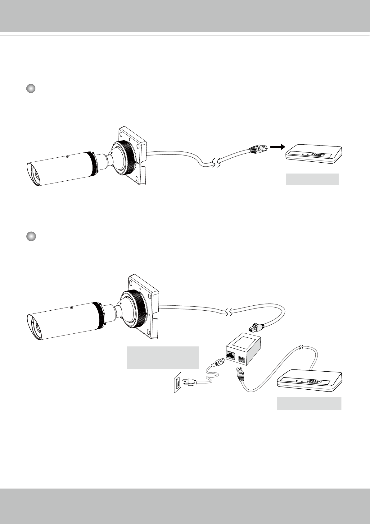
Network Deployment
General Connection (PoE)
When using a PoE-enabled switch
The Network Camera is PoE-compliant, allowing transmission of power and data via a single Ethernet cable. Follow the below illustration to connect the Network Camera to a PoEenabled switch via Ethernet cable.
POW
ER
C
OLL
I
S
LINK
RECEIVE
ION
1
PARTITIO
2
3
N
4
5
PoE Switch
When using a non-PoE switch
Use a PoE power injector (optional) to connect between the Network Camera and a nonPoE switch.
12 - User's Manual
PoE Power Injector
(optional)
L
I
N
POW
ER
C
O
LL
I
S
ION
K
RE
CEIVE
1
PARTITIO
2
3
N
4
5
Non-PoE Switch
VIVOTEK
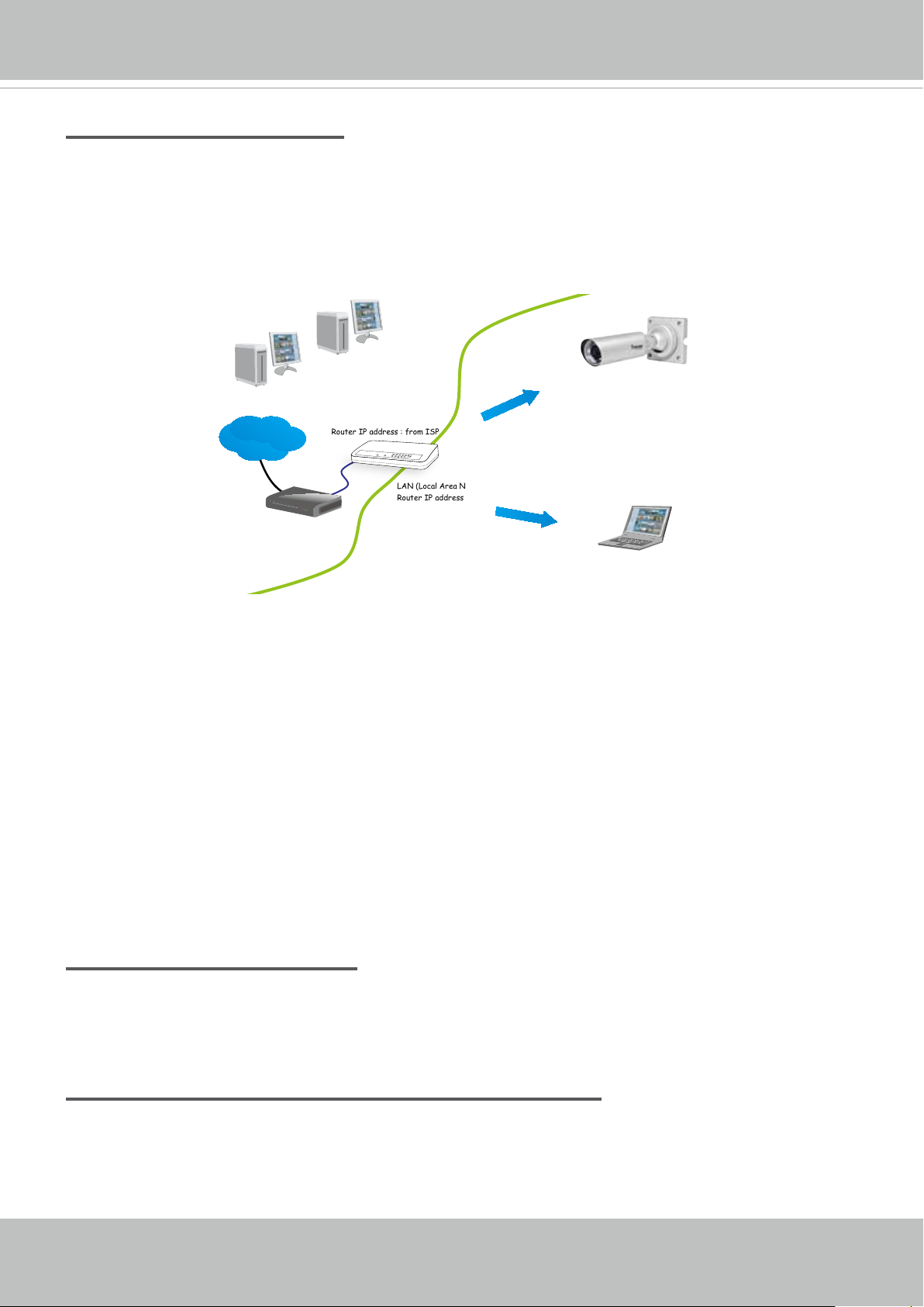
Internet connection via a router
Before setting up the Network Camera over the Internet, make sure you have a router and follow
the steps below.
1. Connect your Network Camera behind a router, the Internet environment is illustrated below.
Regarding how to obtain your IP address, please refer to Software Installation on page 14 for
details.
IP address : 192.168.0.3
Subnet mask : 255.255.255.0
Default router : 192.168.0.1
IP address : 192.168.0.2
Subnet mask : 255.255.255.0
Default router : 192.168.0.1
Internet
Cable or DSL Modem
WAN (Wide Area Network )
Router IP address : from ISP
LINK
POWER
COLLISION
RECEIVE
1
2
PARTITION
3
4
5
LAN (Local Area Network)
Router IP address : 192.168.0.1
2. In this case, if the Local Area Network (LAN) IP address of your Network Camera is
192.168.0.3, please forward the following ports for the Network Camera on the router.
■ HTTP port: default is 80
■ RTSP port: default is 554
■ RTP port for video: default is 5556
■ RTCP port for video: default is 5557
If you have changed the port numbers on the Network page, please open the ports
accordingly on your router. For information on how to forward ports on the router, please refer
to your router’s user’s manual.
3. Find out the public IP address of your router provided by your ISP (Internet Service Provider).
Use the public IP and the secondary HTTP port to access the Network Camera from the
Internet. Please refer to Network Type on page 58 for details.
Internet connection with static IP
Choose this connection type if you are required to use a static IP for the Network Camera.
Please refer to LAN setting on page 57 for details.
Internet connection via PPPoE (Point-to-Point over Ethernet)
Choose this connection type if you are connected to the Internet via a DSL Line. Please refer to
PPPoE on page 58 for details.
User's Manual - 13
VIVOTEK
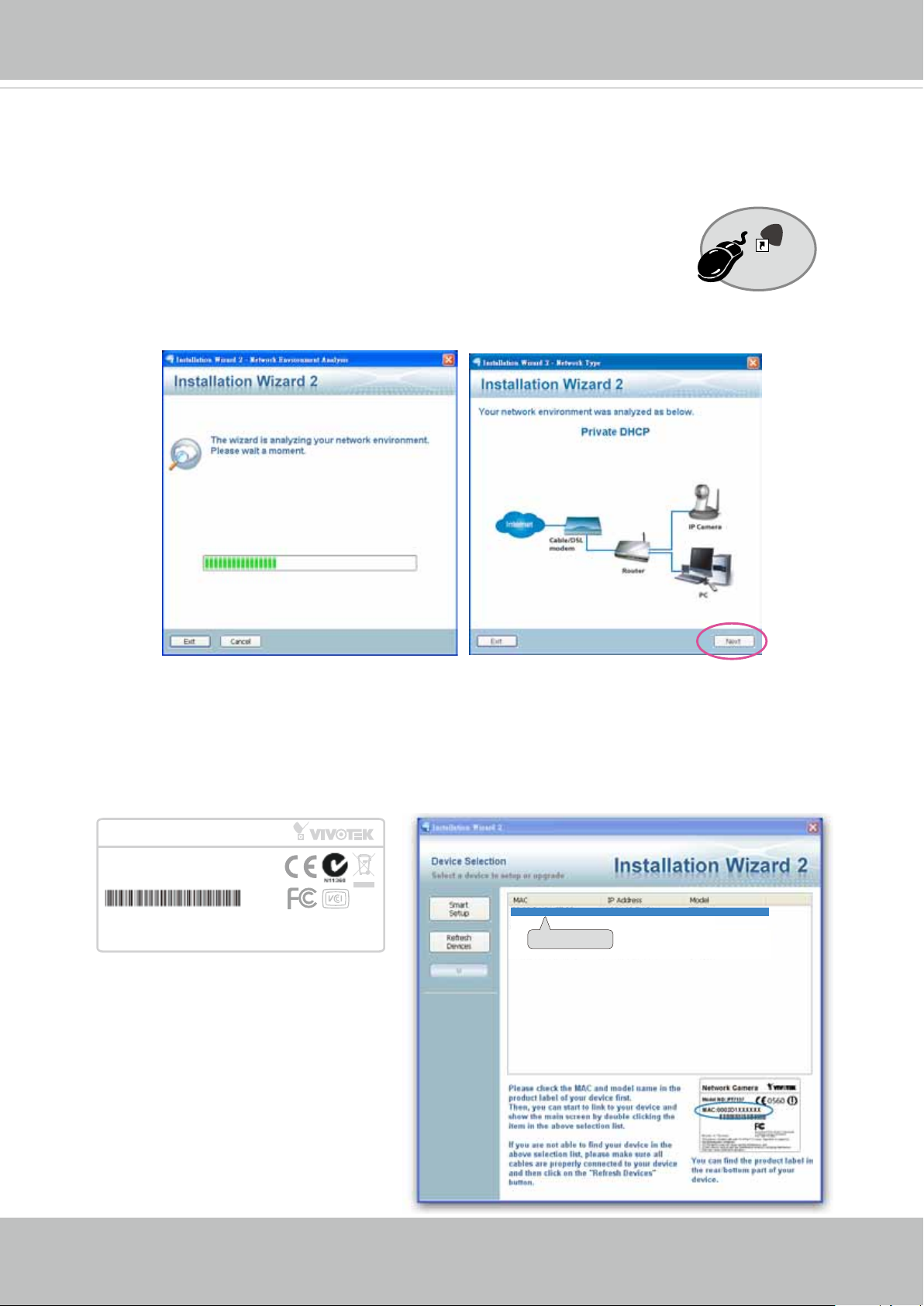
Software Installation
Installation Wizard 2 (IW2), a software included in the product CD, helps you set up your
Network Camera on the LAN.
IW
1. Install IW2 under the Software Utility directory from the software CD.
Double-click the IW2 shortcut on your desktop to launch the program.
2. The program will conduct an analysis of your network environment.
After your network environment is analyzed, please click Next to continue the program.
2
Installation
Wizard 2
3. The program will search for all VIVOTEK network devices on the same LAN.
4. After a brief search, the installer window will prompt. Click on the MAC and model name
that matches the one printed on the product label. You can then double-click on the address
to open a management session with the Network Camera.
Network Camera
Model No: IP8337H-C
MAC:0002D1730202
This device complies with part 15 of the FCC rules. Operation is subject to the following two conditions:
(1)This device may not cause harmful interference, and
(2) this device must accept any interference received, including interference that may cause undesired operation.
Pat. 6,930,709
R o HS
Made in Taiwan
00-02-D1-73-02-02 192.168.5.151 IP8337H-C
0002D1730202
14 - User's Manual
VIVOTEK
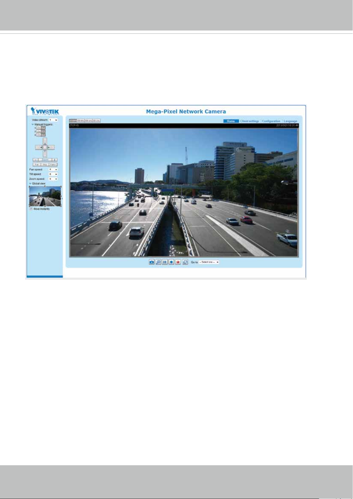
Ready to Use
1. A browser session with the Network Camera should prompt as shown below.
2. You should be able to see live video from your camera. You may also install the 32-channel
recording software from the software CD in a deployment consisting of multiple cameras. For
its installation details, please refer to its related documents.
User's Manual - 15
VIVOTEK
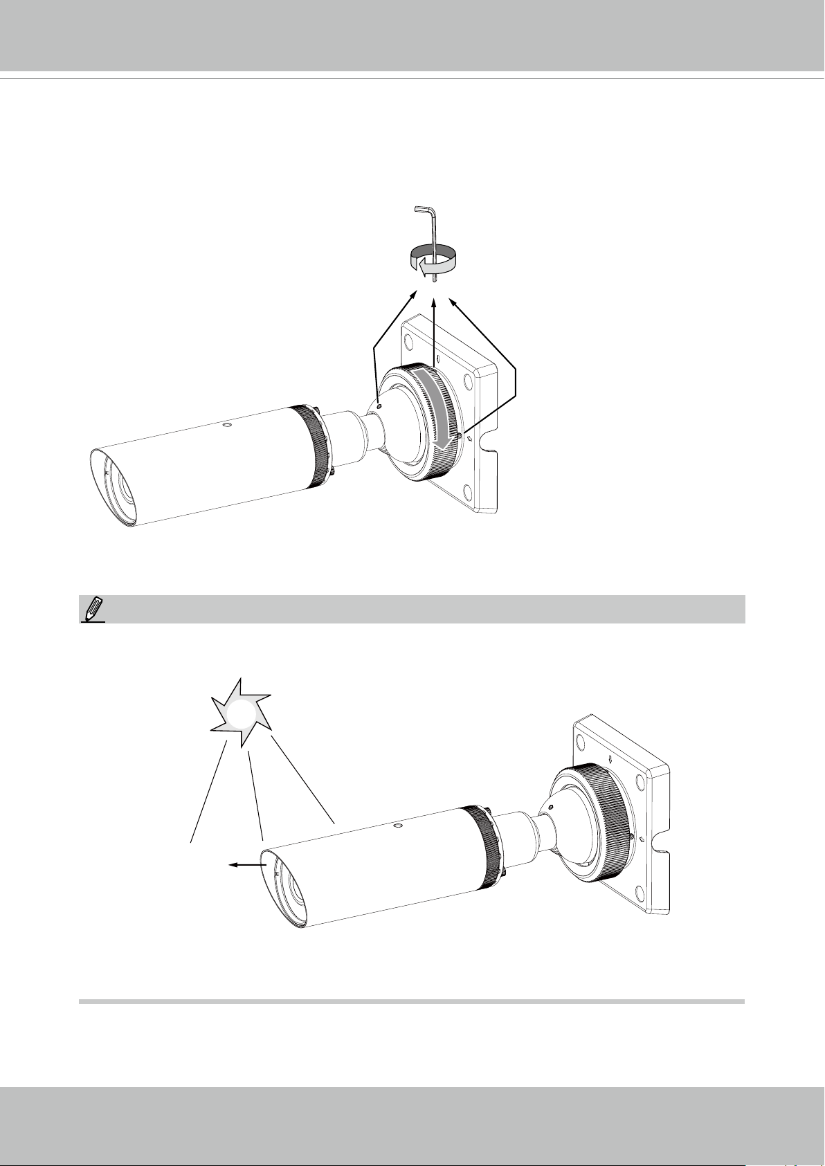
Secure the Shooting Angle
When you are done with tuning the eld of view and obtain a satisfactory image, tighten
the fastening ring and the 3 small hex screws on the ball-swivel bracket.
NOTE:
Orient the camera so that the protruding edge of its sunshield is positioned against the
direction of direct sunlight.
Protruding edge
16 - User's Manual
VIVOTEK
Accessing the Network Camera
This chapter explains how to access the Network Camera through web browsers, RTSP players,
3GPP-compatible mobile devices, and VIVOTEK recording software.
Using Web Browsers
Use Installation Wizard 2 (IW2) to access the Network Cameras on LAN.
If your network environment is not a LAN, follow these steps to access the Netwotk Camera:
1. Launch your web browser (e.g., Microsoft
2. Enter the IP address of the Network Camera in the address eld. Press Enter.
3. Live video will be displayed in your web browser.
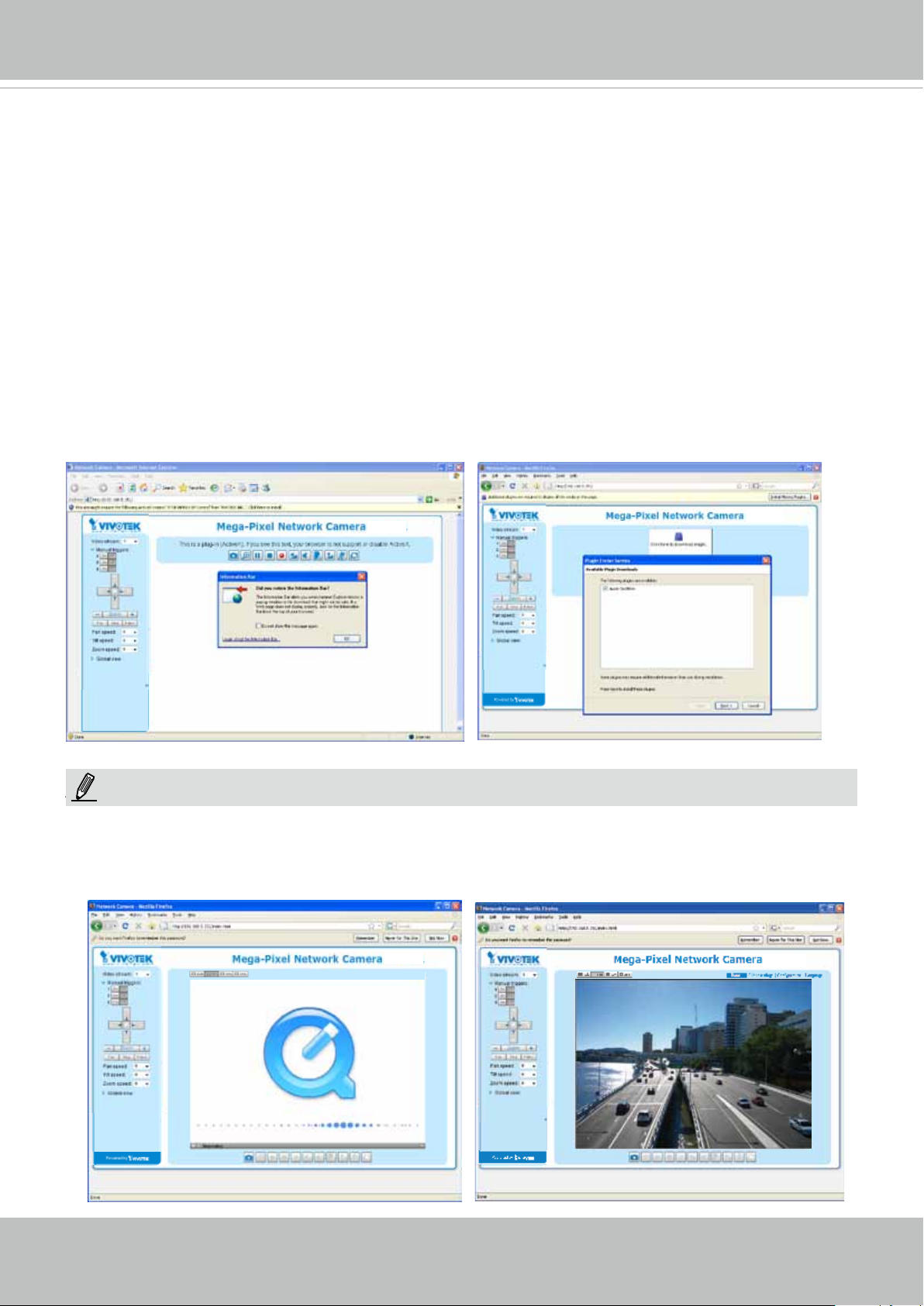
4. If it is the rst time installing the VIVOTEK network camera, an information bar will prompt as
shown below. Follow the instructions to install the required plug-in on your computer.
®
Internet Explorer or Mozilla Firefox).
NOTE
NOTE:
► For Mozilla Firefox or Netscape users, your browser will use Quick Time to stream the live
video. If you don’t have Quick Time on your computer, please download it rst, then launch
the web browser.
User's Manual - 17
VIVOTEK
► By default, the Network Camera is not password-protected. To prevent unauthorized access,
it is highly recommended to set a password for the Network Camera.
For more information about how to enable password protection, please refer to Security on
page 74.
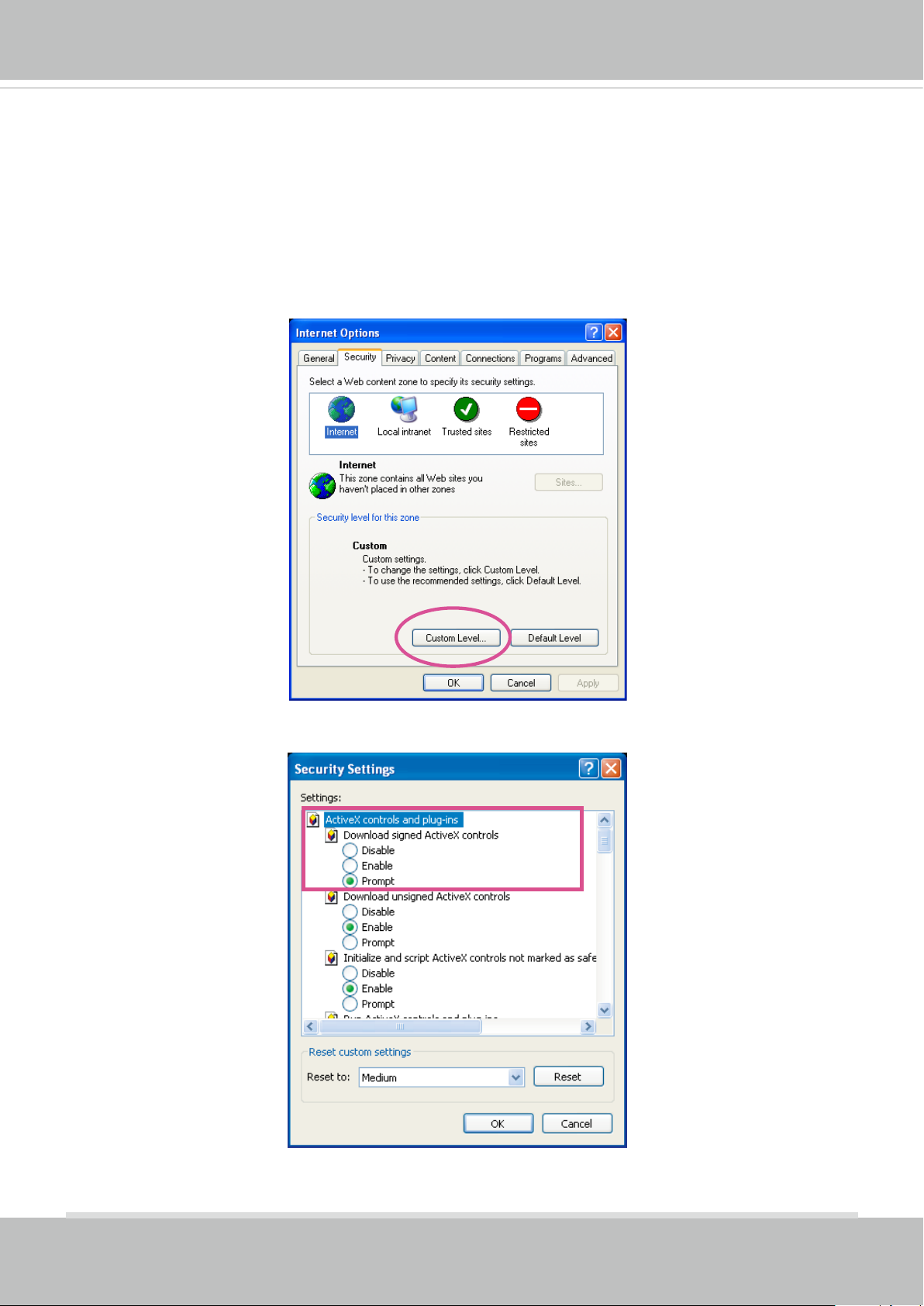
► If you see a dialog box indicating that your security settings prohibit running ActiveX
®
Controls, please enable the ActiveX
Controls for your browser.
®
1. Choose Tools > Internet Options > Security > Custom Level.
2. Look for Download signed ActiveX
®
controls; select Enable or Prompt. Click OK.
3. Refresh your web browser, then install the ActiveX
complete installation.
®
control. Follow the instructions to
18 - User's Manual
VIVOTEK
IMPORTANT:
Currently the Network Camera utilizes 32-bit ActiveX plugin. You CAN NOT open a
•
management/view session with the camera using a 64-bit IE browser.
If you encounter this problem, try execute the Iexplore.exe program from C:\Windows\
•
SysWOW64. A 32-bit version of IE browser will be installed.
On Windows 7, the 32-bit explorer browser can be accessed from here:
•
C:\Program Files (x86)\Internet Explorer\iexplore.exe
If you open a web session from the IW2 utility, a 32-bit IE browser will be opened.
•
Tips
• If you encounter problems with the on-screen control (often related to plug-in compat-
ibility), you can try removing the browser’s cookies.
• The onscreen Java control can malfunction under the following situations:
A PC connects to different cameras that are using the same IP address (or the same
camera running different rmware versions). Removing your browser cookies will solve
this problem.
User's Manual - 19
VIVOTEK
Using RTSP Players
To view the MPEG-4 streaming media using RTSP players, you can use one of the following
players that support RTSP streaming.
Quick Time Player
VLC media player
VLC media player
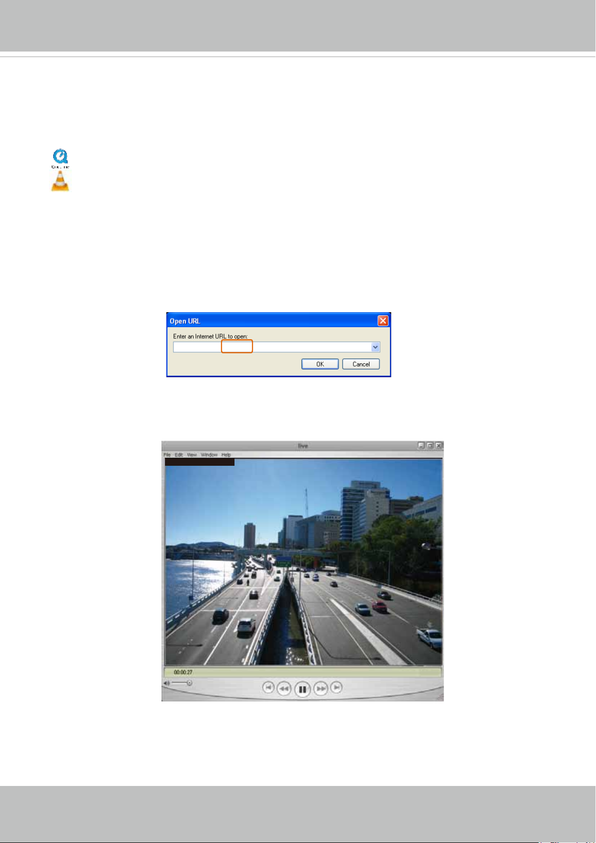
1. Launch the RTSP player.
mpegable Player
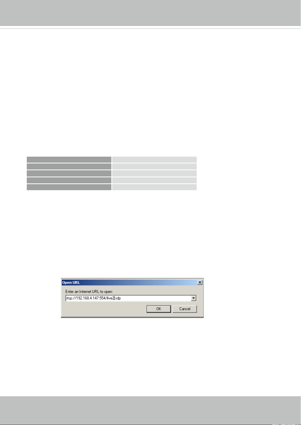
2. Choose File > Open URL. A URL dialog box will pop up.
3. The address format is rtsp://<ip address>:<rtsp port>/<RTSP streaming access name for
pvPlayer
stream1 or stream2>
As most ISPs and players only allow RTSP streaming through port number 554, please set the
RTSP port to 554. For more information, please refer to RTSP Streaming on page 65.
For example:
rtsp://192.168.5.151:554/live.sdp
4. The live video will be displayed in your player.
For more information on how to configure the RTSP access name, please refer to RTSP
Streaming on page 65 for details.
Video 16:38:01 2012/01/25
20 - User's Manual
VIVOTEK
Video quality (Constant bit rate) 128kbps
Using 3GPP-compatible Mobile Devices
To view the streaming media through 3GPP-compatible mobile devices, make sure the Network
Camera can be accessed over the Internet. For more information on how to set up the Network
Camera over the Internet, please refer to Setup the Network Camera over the Internet on page
12.
To utilize this feature, please check the following settings on your Network Camera:
1. Because most players on 3GPP mobile phones do not support RTSP authentication, make
sure the authentication mode of RTSP streaming is set to disable.
For more information, please refer to RTSP Streaming on page 65.
2. As the the bandwidth on 3G networks is limited, you will not be able to use a large video size.
Please set the video streaming parameters as listed below.
For more information, please refer to Stream settings on page 52.
Video Mode H.264
Frame size 384 x 216
Maximum frame rate 15 fps
Intra frame period 1S
3. As most ISPs and players only allow RTSP streaming through port number 554, please set
the RTSP port to 554. For more information, please refer to RTSP Streaming on page 65.
4. Launch the player on the 3GPP-compatible mobile devices (e.g., Quick Time).
5. Type the following URL commands into the player.
The address format is rtsp://<public ip address of your camera>:<rtsp port>/<RTSP streaming
access name for stream # with small frame size and frame rate>.
For example:
You can configure Stream #2 into the suggested stream settings as listed above for live
viewing on a mobile device.
User's Manual - 21
VIVOTEK
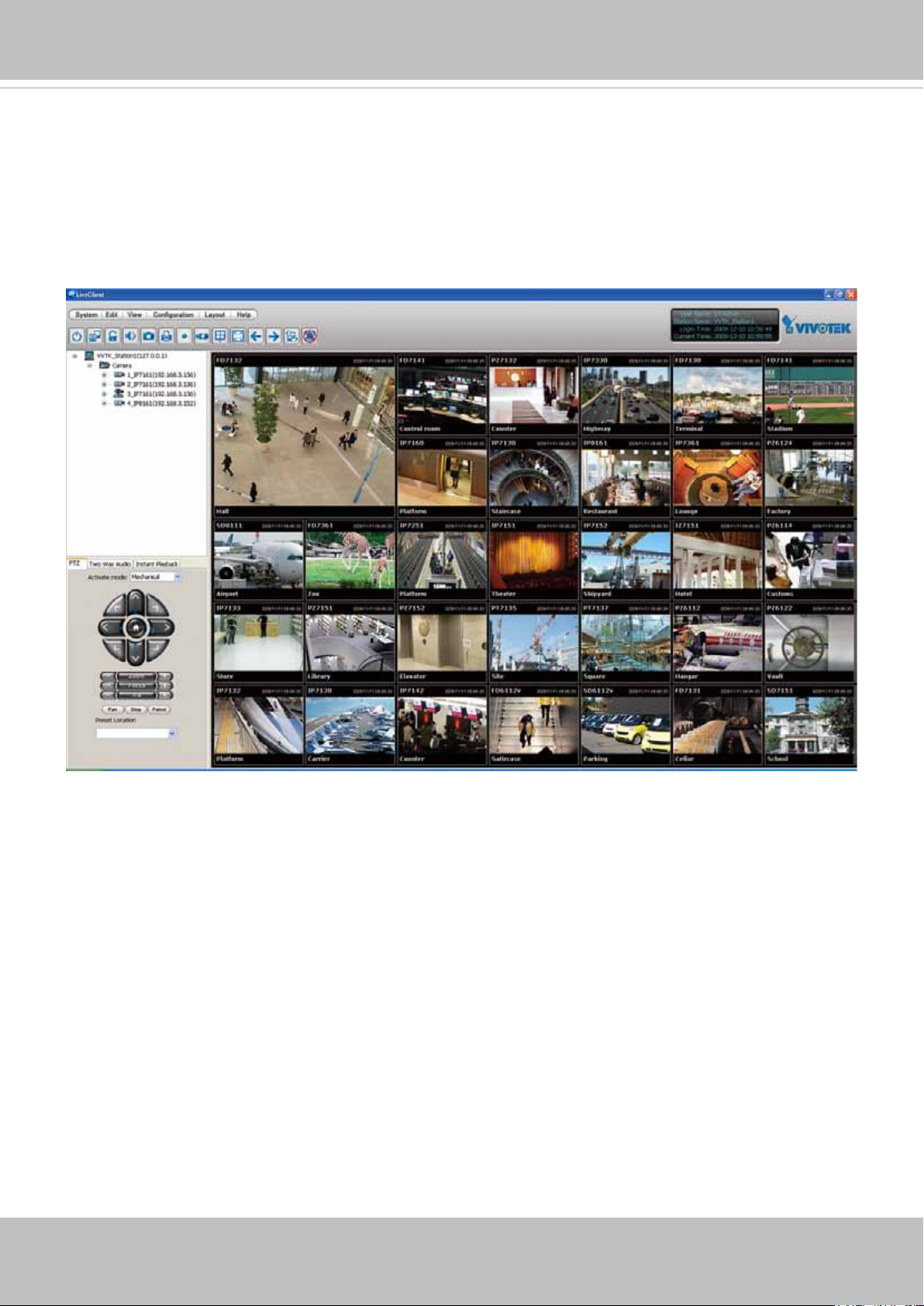
Using VIVOTEK Recording Software
The product software CD also contains an ST7501 recording software, allowing simultaneous
monitoring and video recording for multiple Network Cameras. Please install the recording
software; then launch the program to add the Network Camera to the Channel list. For detailed
information about how to use the recording software, please refer to the user’s manual of the
software or download it from http://www.vivotek.com.
22 - User's Manual
VIVOTEK
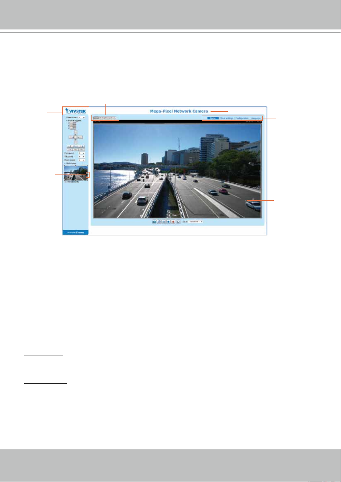
Main Page
This chapter explains the layout of the main page. It is composed of the following sections:
VIVOTEK INC. Logo, Host Name, Camera Control Area, Configuration Area, Menu, and Live
Video Window.
Resize Buttons
VIVOTEK INC.
Logo
Camera Control
Area
Hide Button
Host Name
Configuration
Area
Live View Window
VIVOTEK INC. Logo
Click this logo to visit the VIVOTEK website.
Host Name
The host name can be customized to t your needs. The name can be changed especially there are many
cameras in your surveillance deployment. For more information, please refer to System on page 33.
Camera Control Area
Video Stream: This Network Camera supports multiple streams (streams 1 and 2) simultaneously. You
can select any of them for live viewing. For more information about multiple streams, please refer to page
52 for detailed information.
Manual Trigger: Click to enable/disable an event trigger manually. Please congure an event setting on
the Application page before you enable this function. A total of 3 event conguration can be congured.
For more information about event setting, please refer to page 90. If you want to hide this item on
the homepage, please go to Configuration> System > Homepage Layout > General settings >
Customized button to deselect the “show manual trigger button” checkbox.
User's Manual - 23
VIVOTEK
H.264 Protocol and Media Options
Conguration Area
Client Settings: Click this button to access the client setting page. For more information, please refer to
Client Settings on page 28.
Conguration: Click this button to access the conguration page of the Network Camera. It is suggested
that a password be applied to the Network Camera so that only the administrator can configure the
Network Camera. For more information, please refer to Conguration on page 32.
Language: Click this button to choose a language for the user interface. Language options are available
in: English, Deutsch, Español, Français, Italiano,
日本語
, Português,
簡体中文
, and
繁體中文
. Please
note that you can also change a language on the Conguration page; please refer to page 32.
Hide Button
You can click the hide button to hide or display the control panel.
Resize Buttons
:
Click the Auto button, the video cell will resize automatically to t the monitor.
Click 100% is to display the original homepage size.
Click 50% is to resize the homepage to 50% of its original size.
Click 25% is to resize the homepage to 25% of its original size.
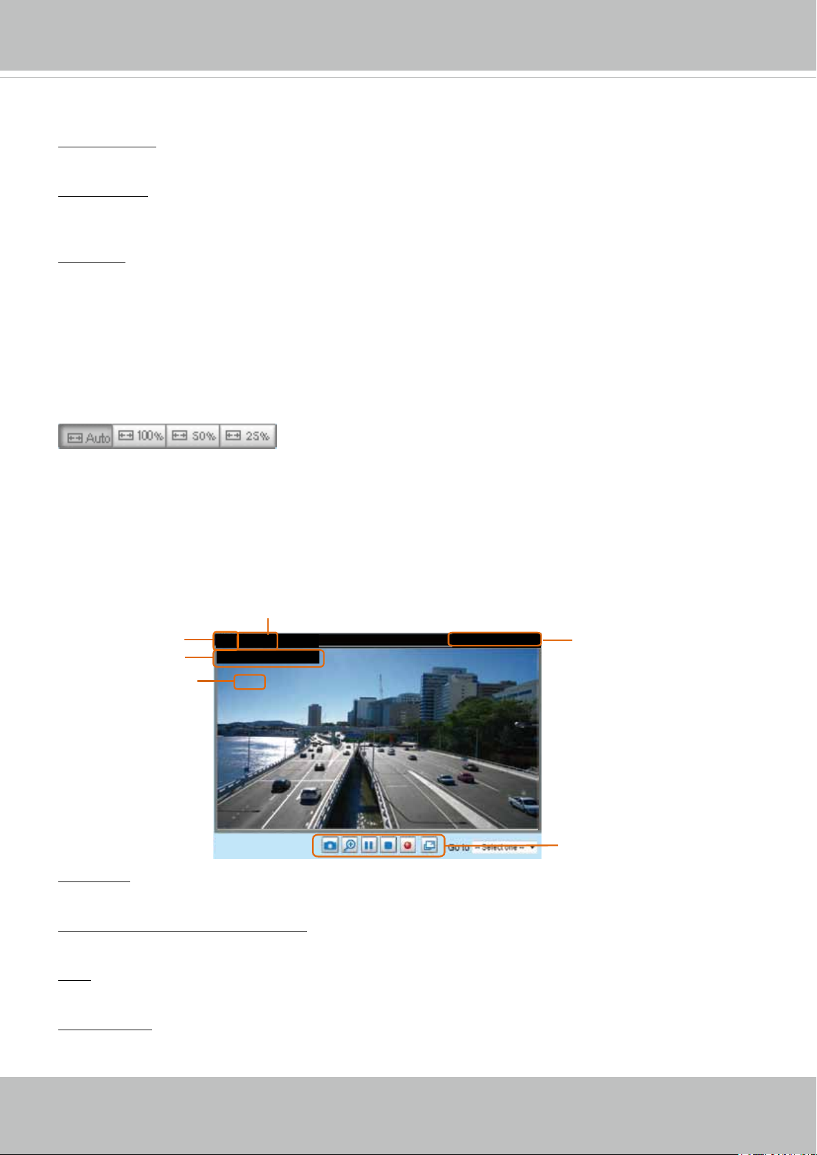
Live Video Window
■ The following window is displayed when the video mode is set to H.264:
Video Title
Title and Time
Zoom Indicator
Video (TPC-AV)
Video 17:08:56 2013/03/25
x4.0
Video Title: The video title can be congured. For more information, please refer to Video Settings on
page 44.
H.264 Protocol and Media Options: The transmission protocol and media options for H.264 video
streaming. For further conguration, please refer to Client Settings on page 28.
2013/03/25 17:08:56
Time
Video Control Buttons
Time: Display the current time. For further conguration, please refer to Media > Image > Genral settings
on page 44.
Title and Time: The video title and time can be stamped on the streaming video. For further conguration,
please refer to Media > Image > General settings on page 46.
24 - User's Manual
VIVOTEK
PTZ Panel: This Network Camera supports “digital“ (e-PTZ) pan/tilt/zoom control, which allows roaming
a smaller view frame within a large view frame. Please refer to PTZ settiings on page 87 for detailed
information.
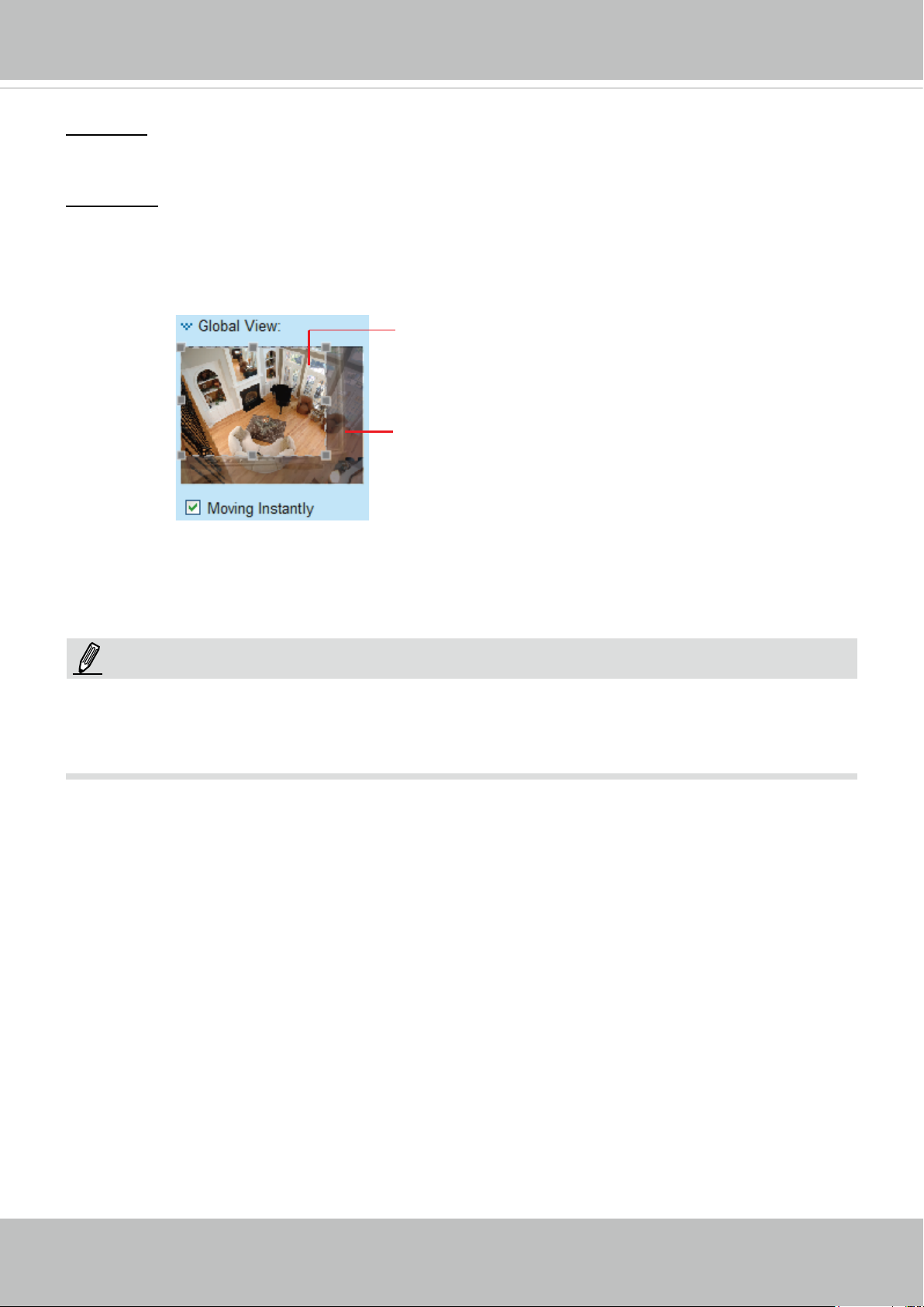
Global View: Click on this item to display the Global View window. The Global View window contains a
full view image (the largest frame size of the captured video) and a oating frame (the viewing region of
the current video stream). The oating frame allows users to control the e-PTZ function (Electronic Pan/
Tilt/Zoom). For more information about e-PTZ operation, please refer to E-PTZ Operation on page 87.
For more information about how to set up the viewing region of the current video stream, please refer to
page 87.
The viewing region of
the curruent video
stream
The largest frame size
Note that the PTZ buttons on the panel are not operational unless you are showing only a portion of the
full image. If the live view window is displaying the full view, the PTZ buttons are not functional.
NOTE:
For a megapixel camera, it is recommended to use monitors of the 24" size or larger, and
are capable of 1600x1200 or better resolutions.
User's Manual - 25
VIVOTEK
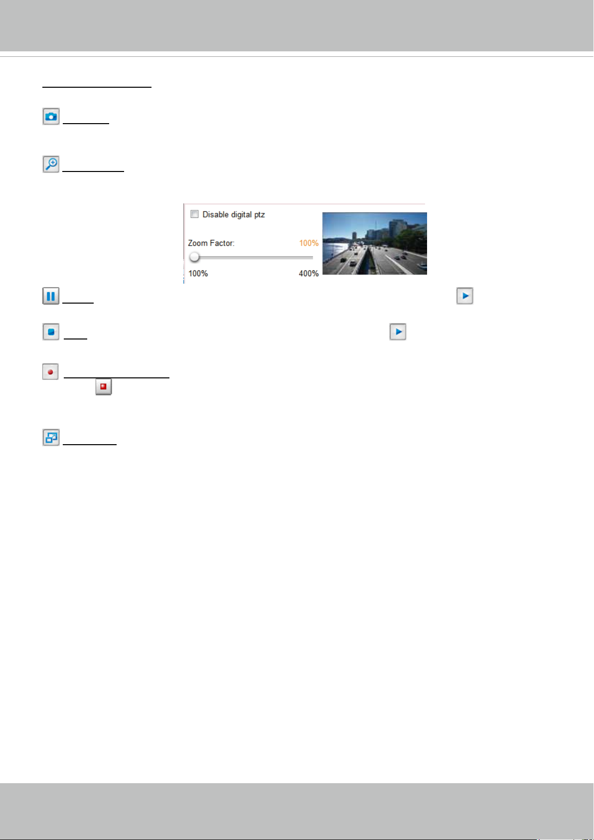
Video Control Buttons: Depending on the Network Camera model and Network Camera conguration,
some buttons may not be available.
Snapshot: Click this button to capture and save still images. The captured images will be displayed
in a pop-up window. Right-click the image and choose Save Picture As to save it in JPEG (*.jpg) or BMP
(*.bmp) format.
Digital Zoom: Click and uncheck “Disable digital zoom” to enable the zoom operation. The navigation
screen indicates the part of the image being magnied. To control the zoom level, drag the slider bar. To
move to a different area you want to magnify, drag the navigation screen.
Pause: Pause the transmission of the streaming media. The button becomes the Resume button
after clicking the Pause button.
Stop: Stop the transmission of the streaming media. Click the Resume button to continue
transmission.
Start MP4 Recording: Click this button to record video clips in MP4 file format to your computer.
Press the
Stop MP4 Recording button to end recording. When you exit the web browser, video
recording stops accordingly. To specify the storage destination and le name, please refer to MP4 Saving
Options on page 29 for details.
Full Screen: Click this button to switch to full screen mode. Press the “Esc” key to switch back to normal
mode.
26 - User's Manual
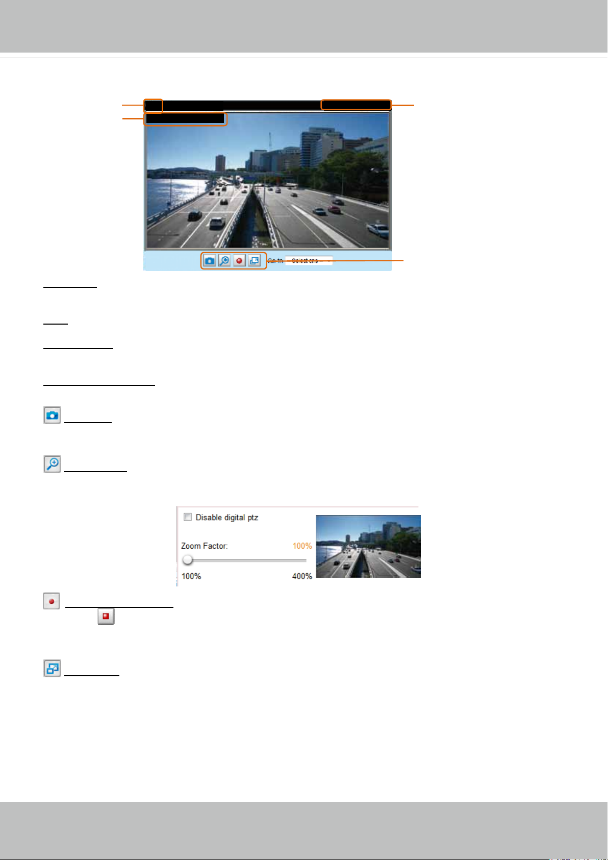
■ The following window is displayed when the video mode is set to MJPEG:
VIVOTEK
Video Title
Title and Time
Video (HTTP-V)
Video 17:08:56 2013/02/25
2013/02/25 17:08:56
Time
Video Control Buttons
Video Title: The video title can be congured. For more information, please refer to Media > Image on
page 46.
Time: Display the current time. For more information, please refer to Media > Image on page 46.
Title and Time: Video title and time can be stamped on the streaming video. For more information, please
refer to Media > Image on page 46
.
Video Control Buttons: Depending on the Network Camera model and Network Camera conguration,
some buttons may not be available.
Snapshot: Click this button to capture and save still images. The captured images will be displayed
in a pop-up window. Right-click the image and choose Save Picture As to save it in JPEG (*.jpg) or BMP
(*.bmp) format.
Digital Zoom: Click and uncheck “Disable digital zoom” to enable the zoom operation. The navigation
screen indicates the part of the image being magnied. To control the zoom level, drag the slider bar. To
move to a different area you want to magnify, drag the navigation screen.
Start MP4 Recording: Click this button to record video clips in MP4 file format to your computer.
Press the
Stop MP4 Recording button to end recording. When you exit the web browser, video
recording stops accordingly. To specify the storage destination and le name, please refer to MP4 Saving
Options on page 29 for details.
Full Screen: Click this button to switch to full screen mode. Press the “Esc” key to switch back to normal
mode.
User's Manual - 27
VIVOTEK
Client Settings
This chapter explains how to select the stream transmission mode and saving options on the
local computer. When completed with the settings on this page, click Save on the page bottom
to enable the settings.
H.264 Protocol Options
H.264/MPEG-4 Protocol Options
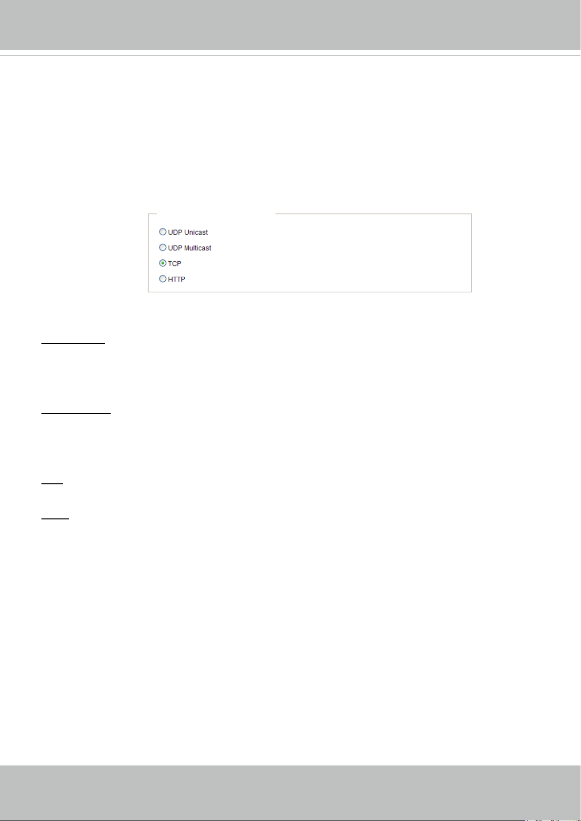
Depending on your network environment, there are four transmission modes of H.264 or MPEG-4
streaming:
UDP unicast: This protocol allows for more real-time audio and video streams. However, network
packets may be lost due to network burst trafc and images may be broken. Activate UDP connection
when occasions require time-sensitive responses and the video quality is less important. Note that each
unicast client connecting to the server takes up additional bandwidth and the Network Camera allows up
to ten simultaneous accesses.
UDP multicast: This protocol allows multicast-enabled routers to forward network packets to all clients
requesting streaming media. This helps to reduce the network transmission load of the Network Camera
while serving multiple clients at the same time. Note that to utilize this feature, the Network Camera must
be configured to enable multicast streaming at the same time. For more information, please refer to
RTSP Streaming on page 65.
TCP: This protocol guarantees the complete delivery of streaming data and thus provides better video
quality. The downside of this protocol is that its real-time effect is not as good as that of the UDP protocol.
HTTP: This protocol allows the same quality as TCP protocol without needing to open specic ports for
streaming under some network environments. Users inside a firewall can utilize this protocol to allow
streaming data through.
28 - User's Manual
VIVOTEK
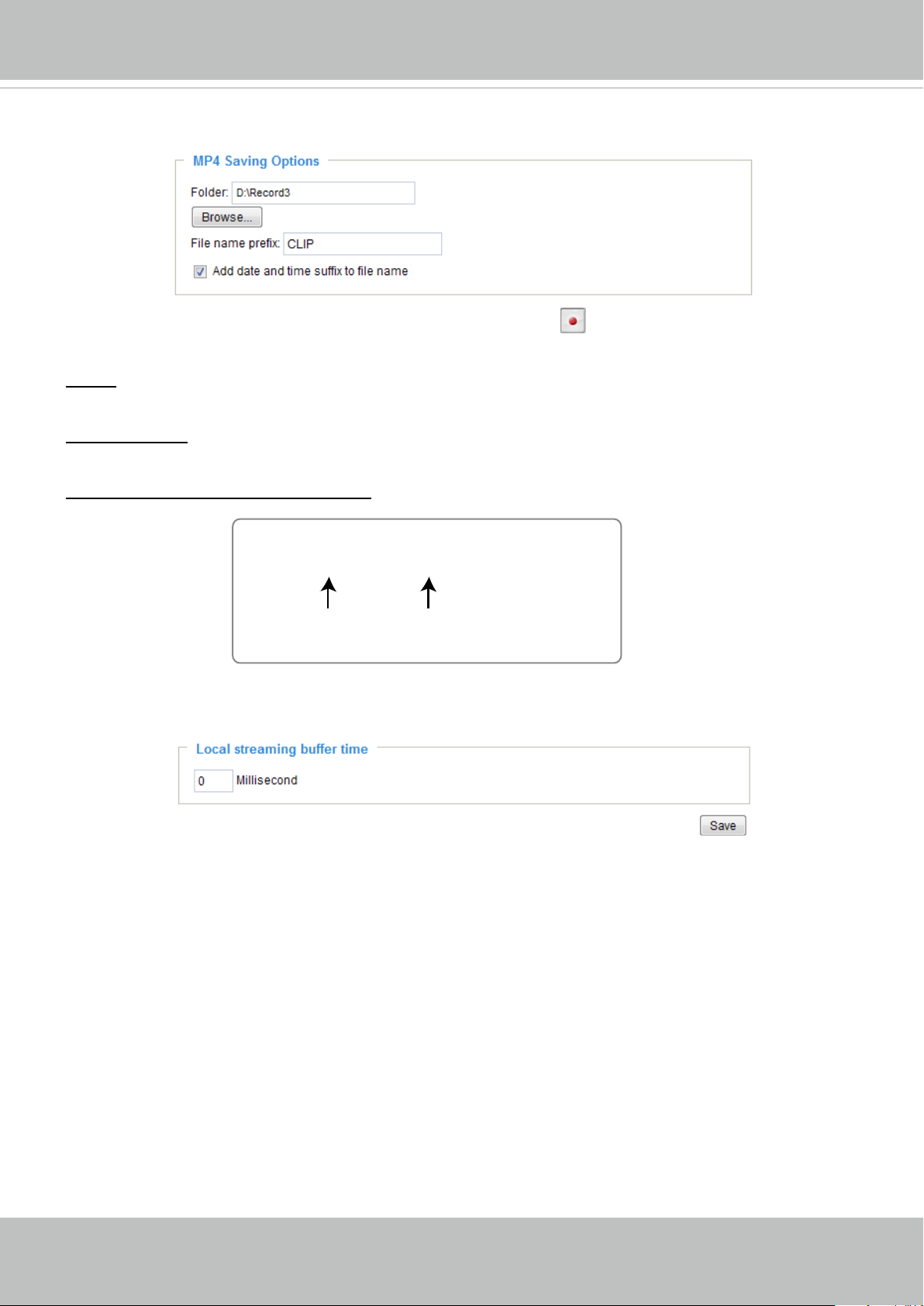
MP4 Saving Options
Users can record live video as they are watching it by clicking Start MP4 Recording on the main
page. Here, you can specify the storage destination and le name.
Folder: Specify a storage destination on your PC for the recorded video files. The location can be
changed.
File name prex: Enter the text that will be appended to the front of the video le name. A specied folder
will be automatically created on your local hard disk.
Add date and time sufx to the le name: Select this option to append the date and time to the end of the
le name.
CLIP_20130321-180853
File name prefix
Date and time suffix
The format is: YYYYMMDD_HHMMSS
Local Streaming Buffer Time
Due to the unsteady bandwidth ow, the live streaming may lag and not be very smoothly. If you enable
this option, the live streaming will be stored temporarily on your PC’s cache memory for a few seconds
before being played on the live viewing window. This will help you see the streaming more smoothly. If
you enter 3,000 Millisecond, the streaming will delay for 3 seconds.
User's Manual - 29

VIVOTEK
Joystick settings
Enable Joystick
Connect a joystick to a USB port on your management computer. Supported by the plug-in
(Microsoft’s DirectX), once the plug-in for the web console is loaded, it will automatically detect if
there is any joystick on the computer. The joystick should work properly without installing any other
driver or software.
Then you can begin to configure the joystick settings of connected devices. Please follow the
instructions below to enable joystick settings.
1. Select a detected joystick, if there are multiple, from the Selected joystick menu. If your joystick
is not detected, if may be defective.
2. Click Calibrate or Congure buttons to congure the joystick-related settings.
NOTE:
• If you want to assign Preset actions to your joystick, the preset locations should be congured in
advance in the Conguration > PTZ page.
• If your joystick is not working properly, it may need to be calibrated. Click the Calibrate button
to open the Game Controllers window located in Microsoft Windows control panel and follow the
instructions for trouble shooting.
• The joystick will appear in the Game Controllers list in the Windows Control panel. If you want to
check out for your devices, go to the following page: Start -> Control Panel -> Game Controllers.
30 - User's Manual
 Loading...