

Page 1
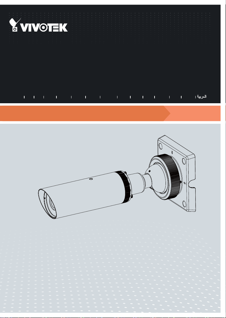
IP8332-C
Bullet
Network Camera
Quick Installation Guide
繁中 日本語
English
Outdoor • Day & Night • Weather-proof • Cable Management
簡中
Français
Deutsch
Español Português
Italiano
Türkçe
Polski
Русский
Česky Svenska
Page 2
Warning Before Installation
5
1
0
0
0
0
2
2
1
G
English
Power off the Network Camera as
soon as smoke or unusual odors are
detected.
Do not place the Network Camera on
unsteady surfaces.
Do not insert sharp or tiny objects
into the Network Camera.
Replacing or failing to properly
install the waterproof components,
e.g., cables or cable glands, will void
our IP65/66/67 warranty.
1
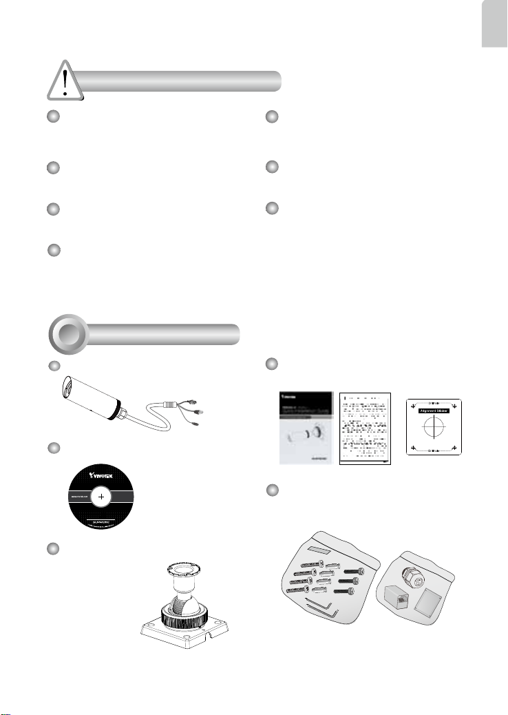
Package Contents
IP8332-C
Software CD
Refer to your user’s manual for the
operating temperature.
Do not touch the Network Camera
during a lightning storm.
Do not drop the Network Camera.
Quick Installation Guide / Warranty
Card / Alignment Sticker
L-type Hex Key Wrench / Dessicant
Bag / Screws / RJ45 Female-Famale
Coupler / Waterproof Connector
Ball Swivel
Mount Bracket
EN-1
Page 3
2
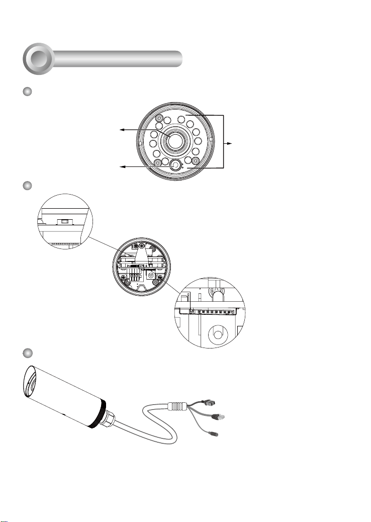
Physical Description
Front Panel
Lens
Light Sensor
Rear Panel
Reset Button
IR LEDs
MicroSD/SDHC
Card Slot
Connectors
General I/O Terminal Block
Ethernet 10/100 RJ45 Plug
Power Cord Socket (Black)
EN-2
Page 4

3
Hardware Installation
If you prefer installing a MicroSD card as onboard storage:
1. Loosen the waterproof connector, and then remove the rubber seal, and the
waterproof connector.
2. Loosen and open the rear cover.
3. Install a MicroSD/SDHC card.
4. Tear down the aluminum foil vacuum bag and take out the dessicant bag. Attach the
supplied dessicant bag to the inner side of the Network Camera. (Please replace the
dessicant bag with a new one every time you open the rear cover.)
5. Make sure all cable lines are securely connected.
icro
M
SD
2
3
English
1
4
Silica gel
IMPORTANT:
Although the camera and the cable gland on the camera's end are waterproof, the cable
molding at the other end is not waterproof.
Measures should be taken to prevent water from leaking in through the cable-end
molding, such as the use of expanding foam sealant, putties, and so on. Note that the
cable gland on the camera should also be securely fastened to attain its waterproof
functionality.
Waterproof
Not Waterproof
Cable Gland
Cable Molding
EN-3
Page 5

5. Tighten the rear cover, rubber seal and waterproof connector.
5
6. Pass the cables through the center of the ball swivel mount bracket, one at a time.
7. Fasten the bracket to the camera using 3 hex socket screws.
7
NOTE:
The camera weighs up to 1.28 kgs.
Make sure the mounting surface can
support this camera.
6
8. Loosen the fastening ring on the mount bracket, and aim the camera at the area of
your interest. When done, tighten the fastening ring.
Fastening ring
75º Tilt
360º Pan
EN-4
Page 6

GND
DI
AC24V
AC24V
9. Secure the Network Camera to a wall or ceiling.
9
4
Network Deployment
General Connection (without PoE)
1. If you have external devices such as
sensors and alarms, make connections
from general I/O terminal block.
Ceiling Mount
Wall Mount
GND : Ground
DI : Digital Input
AC24V : 24VAC24V : 24V+
English
2. Use the supplied RJ45 female/female
coupler to connect the Network Camera
to a switch.
3. Connect the power cable from the
Network Camera to a power outlet.
EN-5
L
I
N
K
POW
ER
C
O
LL
I
S
RE
ION
CEIVE
1
PARTITIO
2
3
N
4
5
Page 7

Power over Ethernet (PoE)
When using a PoE-enabled switch
The Network Camera is PoE-compliant, allowing transmission of power and data
via single Ethernet cable. Follow the below illustration to connect the Network
Camera to a PoE-enabled switch via Ethernet cable.
POW
ER
C
O
LL
I
S
ION
1
2
3
4
PoE Switch
When using a non-PoE switch
Use a PoE power injector (optional) to connect between the Network Camera and
a non-PoE switch.
PoE Power Injector
(optional)
L
I
N
K
RE
CEIVE
PARTITIO
N
5
EN-6
L
I
N
K
POW
ER
C
O
LL
I
RE
S
ION
CEIVE
1
PARTITIO
2
3
N
4
5
Non-PoE Switch
Page 8

5
Assigning an IP Address
1. Install the "Installation Wizard 2" from the Software Utility directory on the software
CD.
2. The program will conduct an analysis of your network environment. After your network
is analyzed, please click on the "Next" button to continue the program.
3. The program will search for VIVOTEK Video Receivers, Video Servers or Network
Cameras on the same LAN.
4. After a brief search, the main installer window will pop up. Double-click on the MAC
address that matches the one printed on the camera label or the S/N number on the
package box label to open a browser management session with the Network Camera.
6
Ready to Use
1. A browser session with the Network Camera should prompt as shown below.
2. You should be able to see live video from your camera. You may also install the
32-channel recording software from the software CD in a deployment consisting of
multiple cameras. For its installation details, please refer to its related documents.
English
For further setup, please refer to user’s manual on the software CD.
EN-7
Page 9

6
Secure the Shooting Angle
When you are done with tuning the eld of view and obtain a satisfactory image, tighten
the fastening ring and the 3 small hex screws on the ball-swivel bracket.
NOTE:
Orient the camera so that the protruding edge of its sunshield is positioned against the
direction of direct sunlight.
Protruding edge
EN-8
Page 10

P/N:625018500G Rev. 1.0
All specications are subject to change without notice.
c
Copyright 2012 VIVOTEK INC. All rights reserved.
VIVOTEK INC.
6F, No.192, Lien-Cheng Rd., Chung-Ho, New Taipei City, 235, Taiwan, R.O.C.
|T: +886-2-82455282| F: +886-2-82455532| E: sales@vivotek.com
VIVOTEK USA, INC.
2050 Ringwood Avenue, San Jose, CA 95131
|T: 408-773-8686| F: 408-773-8298|E : salesusa@vivotek.com
 Loading...