

Page 1
IP816A-LPC
License Plate Capturing Solution
Quick Installation Guide
2MP • WDR Pro • Remote back Focus • Snapshot Focus
Ordering part no.:
180000600G - IP816A-LPC(Street)
Document part no.: 625030101G
Rev. 1.1
Page 2
CAUTION:
TO REDUCE RISK OF FIRE OR ELECTRIC SHOCK, DO NOT REMOVE COVER.
NO USER SERVICEABLE PARTS INSIDE.
REFER SERVICING TO QUALIFIED SERVICE PERSONNEL.
UNPACKING:
Unpack carefully. Electronic components can be damaged if improperly handled or
dropped. If an item appears damaged in shipment, place it properly in its carton and
notify the shipper.
IMPORTANT!:
1. Read and follow Instructions: All operating and user instructions should be read and
followed before the unit is to be operated.
2. Electrical Connections: Only a qualied electrician is allowed to make electrical
connections.
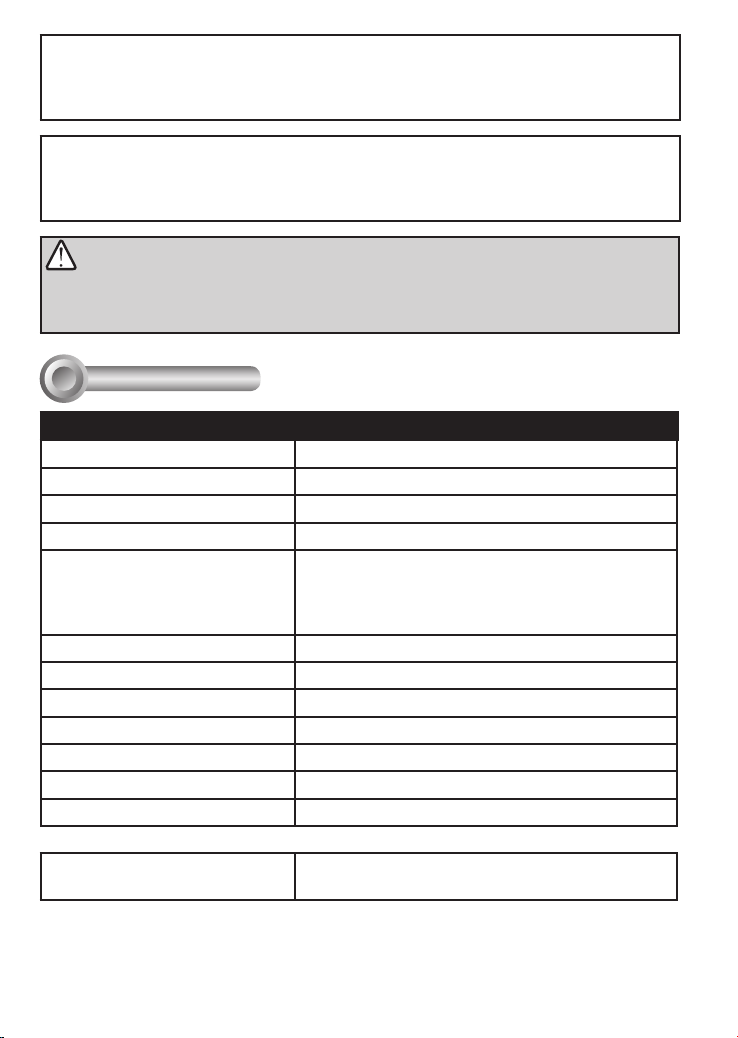
Specications
I
Model Number IP816A-LPC enclosure
Power Input 24VAC (+/-10%)
Rating Current 3.5 A
Heater Control 15°C (ON) / 25°C (OFF)
Blower Control 35°C (ON) / 25°C (OFF)
Environmental Operation Temp. AE-237 Single heater: -20°C ~ +50°C
Protection Level IP66, IK10
Temper Glass thickness 4mm
Mounting Bracket Fully-cable Management
Construction Die-cast Aluminum Alloy
Coating White epoxy powder coating
Dimensions 400 (L) x 130 (W) x 108 (H) mm
Net Weight 2900g
AE-236 Double heater: -40°C ~ +50°C (heater is
on at -40°C. When temperature reaches -10°C,
camera is powered on)
IR light angle of beam
(different IR light units)
AI-104-010 Street: 10º
2
Page 3
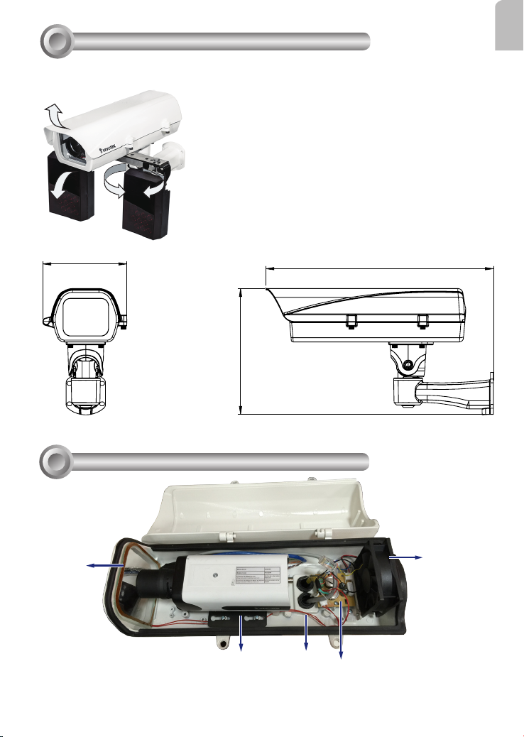
Mounting Conguration & Dimensions
II
Swivel Positions and Directions
English
171
Component Description
III
Heater
Heater for the dual-heater,
-40ºC model
256
Waterproof cable
gland
Power Supply Unit
3
462.7
Circulation
fan
Page 4
Installation Suggestions
IV
If you plan to install this camera enclosure into a tropical, sea coastal, or an environment
where salt water or corrosive industrial waste water/moist are present, please seal each
stainless steel screws and ttings with a silicon grease compounds. This will help prevent
electrolysis to occur and extend the life span of the camera and housing.
IMPORTANT:
1. Disconnect devices: A readily accessible disconnect device in the building installation wiring
should be incorporated.
2. Electrical Connection: Only a qualied electrician is allowed to make electrical connections.
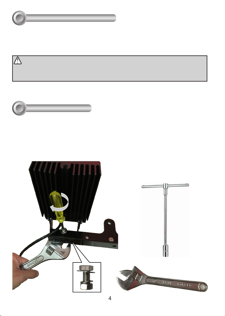
Installation
V
Loosen the socket screws using the included L-type hex key wrench, and open the
1.
cover.
Secure the IR light units to the included iron brackets using a crescent wrench and a
2.
socket wrench.
4
Page 5
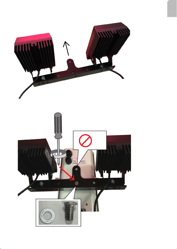
Secure both IR light units to the included iron bracket in the orientation shown below.
To the front of
enclosure
Secure the IR light bracket to the bottom of th enclosure. Secure one screw only at this
3.
stage of installation.
English
5
Page 6
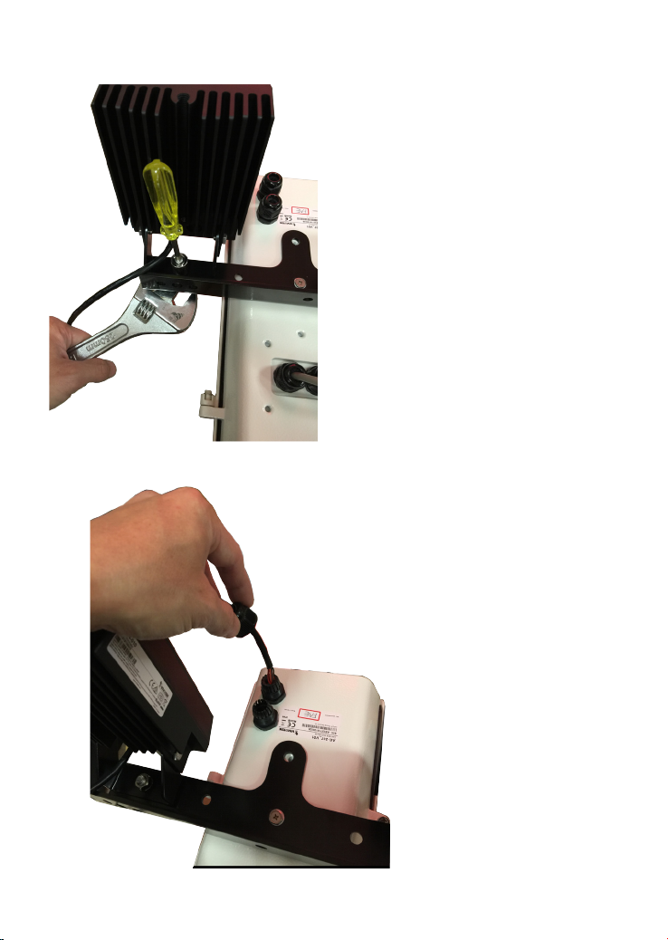
Adjust the IR lights' shooting direction and tighten up the mount screws. You may need
4.
to adjust the shooting angles later.
Pass the IR light units' signal wires through the waterproof connectors on the front.
5.
6
Page 7

Loosen the retention hex screws of the enclosure. To access the screws, you can push
6.
the IR bracket to the side.
English
7
Page 8

Check the inside of the enclosure to make sure the I/O wires can reach the power
7.
supply unit inside. An approximate of 25cm cable length is required. Install and tighten up
the waterproof connectors.
8
Page 9

Prepare the AC24V power wires and a CAT5e Ethernet cable. Pass them through the
8.
waterproof connectors.
English
You may need to remove the RJ45 connector, and use a crimping tool to connect the
Ethernet wires to an RJ45 connector inside the enclosure. Use an Ethernet cable of the
width of 5 ~ 6.5mm.
o: white/orange stripe
O: orange solid
g: white/green stripe
B: blue solid
b: white/blue stripe
G: green solid
br: white/brown stripe
BR: brown solid
o
O
g
B
b
G
br
BR
1
2
3
4
5
6
7
8
9
Page 10

When done, tighten up the waterproof connectors.
9.
Assemble the camera components, e.g., the CS ring and lens module. Align the
10.
buffer pad with the mounting hole at the bottom of the camera (the label side).
LPC
Place the mounting plate on top of the buffer pad and then secure it to the camera.
11.
You may need adjust its position so that the lens module can ush align with the tempered
glass.
10
Page 11

Secure the camera to the enclosure by securing screws through the keyhole slots.
12.
Attach the AC24V power wires and power inputs from the IR light units to the terminal
13.
connector. Connect the Brown and Orange (26AWG) wires from both IR units to the
terminal. Since AC 24V is polarity free, Connect AC 24V from outer source, 24V inputs for
IR (2 pairs), and 24V inputs for camera, all to the same terminal connector.
English
AC24V
power
Power to IR:
Brown & Orange
11
Page 12

Connect the power inputs from another IR light unit to the same terminal connector.
12
Page 13

Listed below is the color scheme for wires coming fom the IR light units.
Description Color Gauge
IR status DO- Orange (26AWG)
IR status DO+ Brown (26AWG)
LED ON/OFF mode DO- Black (26AWG)
LED ON/OFF mode DO+ Red (26AWG)
Input(V-): 24V AC/DC or 12V DC Orange (20AWG)
Input(V+): 24V AC/DC or 12V DC Brown (20AWG)
Output(V-): Volts same as input Black (20AWG)
Output(V+): Volts same as input Red (20AWG)
Prepare two power lines as the 24V inputs for the camera. Connect the input lines
14.
from the enclosure's terminal to that on the camera. Also connect the DO- (black) and the
DO+ (red) lines from the IR unit to the camera's DI pins on the terminal connector. You
only need to connect one pair of day/night mode DO wires to the camera (the other unit
will automatically turn on when light level reaches the preset threshold).
AC/DC pwr
AC/DC pwr
DO+
DO-
DI1+
DI2+
DI3+
DI-
RS485-
RS485+
English
The day/night mode DO connection enables the synchronization of IR light and the
automated day/night switching mechanism on the camera.
13
Page 14

Having the wiring done inside the enclosure, you can install the enclosure bracket to
15.
a preferred location at your installation site. Drill mounting holes and a cable routing hole (if
preferred) on a wall. Install the bracket.
Lift the whole enclosure up to the installation position, and pass the 24V power wire
16.
and the Ethernet cables through the bracket.
14
Page 15

Mount the enclosure on to the installed bracket, and secure the connection by
17.
tightening the 4 socket screws. Due to the weight of the enclosure (5.5kg), it is best to
have two men mounting the enclosure.
Adjust zoom and focus and open a web session with the camera to tune for the
18.
best image. When zoom and focus is done, Close the top cover and fasten the top cover
screws.
English
15
Page 16

Close the top cover of the enclosure, tighten the screws,and secure another screw to
19.
the IR bracket.
16
Page 17

Firmware congurable options:
20.
Open a web session with the camera. Make sure that external IR is turned on in the night
mode, and that the IR cut lter option is synchronized with the digital input you connected
(default is DI1).
Use the Media > Focus function to tune for a best image focus on your target area.
English
17
Page 18

In the Conguration > Media > Image settings page, select an application scenario, LPC
street or LPC parking lot. Related parameters, such as shutter time, will be automatically
change for the scenario.
If preferred, e.g., shooting fast moving vehicles, select the 60fps frame rate.
18
Page 19

In the night mode, check if the input signals are correctly detected. You may simulate the
night mode by blocking the IR unit's light sensor. Change the triggering parameters when
necessary.
If your target area is a stretched out eld of view, such as shooting a part of a highway,
nding the best focus can be a problem. You can use the Snapshot Focus utility to make
sure you acquire clear images of the license plates of passing vehicles.
English
19
Page 20

Operation Procedure:
1. Press the Snapshot Recording button, e.g.,
when a car is passing the eld of view. A short,
2.5 seconds of video recording will be available
(including 1 second of pre-recording and
another second of post-recording).
2. The recording takes place on Stream 1 with a
focusing result calculated from the full of the
current eld of view.
3. The Snapshot Focus comes with an embedded
Quick time player. Users can review the
current focusing results on a viewing window.
Users can also use the left arrow key on
their keyboard to go through the recording in
a frame-by-frame manner (after the video is
played once).
In this way, an installer can immediately
examine whether the focus is optimal when
a fast going car is captured by video. If not,
he can tune the focus again and review the
imaging result until satised.
4. Users can also download the short recording
clip to a PC. Note that if the Snapshot Focus
page is refreshed or the web session is closed,
the recording will be erased.
Note that you can use the arrow buttons on the
sides of the Focus tuning bar to find the best
focus.
20
 Loading...