

Page 1
IP Surveillance
IP7130
I
P
S
urve
illan
c
e
Tamper Detection Dual Streams PoE
Page 2

VIVOTEK - A Leading Provider of Multimedia Communication Solutions
2 - User's Manual
Table of Contents
Overview.......................................................................................................................................................3
Read Before Use �������������������������������������������������������������������������������������������������������������������������������������3
Package Contents ����������������������������������������������������������������������������������������������������������������������������������� 3
Physical Description �������������������������������������������������������������������������������������������������������������������������������� 4
Network Deployment ������������������������������������������������������������������������������������������������������������������������������� 7
Software Installation ������������������������������������������������������������������������������������������������������������������������������ 10
Ready to Use ����������������������������������������������������������������������������������������������������������������������������������������� 11
Accessing the Network Camera .................................................................................................................12
Using Web Browsers �����������������������������������������������������������������������������������������������������������������������������12
Using RTSP Players ������������������������������������������������������������������������������������������������������������������������������14
Using 3GPP-compatible Mobile Devices �����������������������������������������������������������������������������������������������15
Using VIVOTEK Recording Software ���������������������������������������������������������������������������������������������������� 16
Main Page ..................................................................................................................................................17
Client Settings ............................................................................................................................................21
Conguration ..............................................................................................................................................23
System ��������������������������������������������������������������������������������������������������������������������������������������������������24
Security �������������������������������������������������������������������������������������������������������������������������������������������������26
HTTPS ���������������������������������������������������������������������������������������������������������������������������������������������������27
Network �������������������������������������������������������������������������������������������������������������������������������������������������32
DDNS ����������������������������������������������������������������������������������������������������������������������������������������������������43
Access List ��������������������������������������������������������������������������������������������������������������������������������������������45
Audio and Video ������������������������������������������������������������������������������������������������������������������������������������ 48
Motion Detection �����������������������������������������������������������������������������������������������������������������������������������55
Camera Tampering Detection ���������������������������������������������������������������������������������������������������������������57
Application ���������������������������������������������������������������������������������������������������������������������������������������������61
Recording ���������������������������������������������������������������������������������������������������������������������������������������������� 74
System Log �������������������������������������������������������������������������������������������������������������������������������������������77
View Parameters ����������������������������������������������������������������������������������������������������������������������������������� 78
Maintenance ������������������������������������������������������������������������������������������������������������������������������������������79
Appendix ....................................................................................................................................................83
URL Commands for the Network Camera ���������������������������������������������������������������������������������������������83
Technical Specications ����������������������������������������������������������������������������������������������������������������������123
Technology License Notice ������������������������������������������������������������������������������������������������������������������124
Electromagnetic Compatibility (EMC) ��������������������������������������������������������������������������������������������������125
Page 3

VIVOTEK - A Leading Provider of Multimedia Communication Solutions
User's Manual - 3
Overview
VIVOTEK’s IP7130 fixed network camera is an economical and easy-to-use surveillance system
designed for indoor applications such as ofces, banks, and retail stores.
This camera comes with the tamper detection feature, which detects data loss from camera tampering in
real-time. When the camera is blocked, redirected, or spray-painted, security staff
will be alerted immediately in accordance with the camera settings. With its dual-stream feature, the
IP7130 also allows two video streams to be delivered in a different resolutions, frame rates, and image
qualities for individual recording or bandwidth demands� Images can be displayed in VGA format for real-
time monitoring while displayed on a 3GPP mobile phone in lower resolution, giving users a higher level
of exibility for dealing with camera images on different platforms. The integrated 802.3af compliant PoE
function reduces cabling clutter, making IP7130 a cost-effective surveillance system.
With other advanced features such as two-way audio via SIP protocol, digital I/O, HTTPS encryption,
and the included 32-CH central management software, IP7130 is the camera of choice for customers
requiring value in their investment�
Read Before Use
The use of surveillance devices may be prohibited by law in your country� The Network Camera is not
only a high-performance web-ready camera but can also be part of a exible surveillance system. It is
the user’s responsibility to ensure that the operation of such devices is legal and complies with all privacy
laws before installing this unit for its intended use�
It is important to rst verify that all contents received are complete according to the Package Contents
listed below� Take note of the warnings in the Quick Installation Guide before the Network Camera is
installed; then carefully read and follow the instructions in the Installation chapter to avoid damage due to
faulty assembly and installation� This also ensures the product is used properly as intended�
The Network Camera is a network device and its use should be straightforward for those who have basic
networking knowledge. It is designed for various applications including video sharing, general security/
surveillance, etc. The Configuration chapter suggests ways to best utilize the Network Camera and
ensure proper operations. For more creative and professional developers, the URL Commands of the
Network Camera section serves as a helpful reference to customizing existing homepages or integrating
with the current web server�
Package Contents
■ IP7130
■ Power Adapter
■ Camera Stand
■ Software CD
■ Warranty Card
■ Quick Installation Guide
Page 4
VIVOTEK - A Leading Provider of Multimedia Communication Solutions
4 - User's Manual
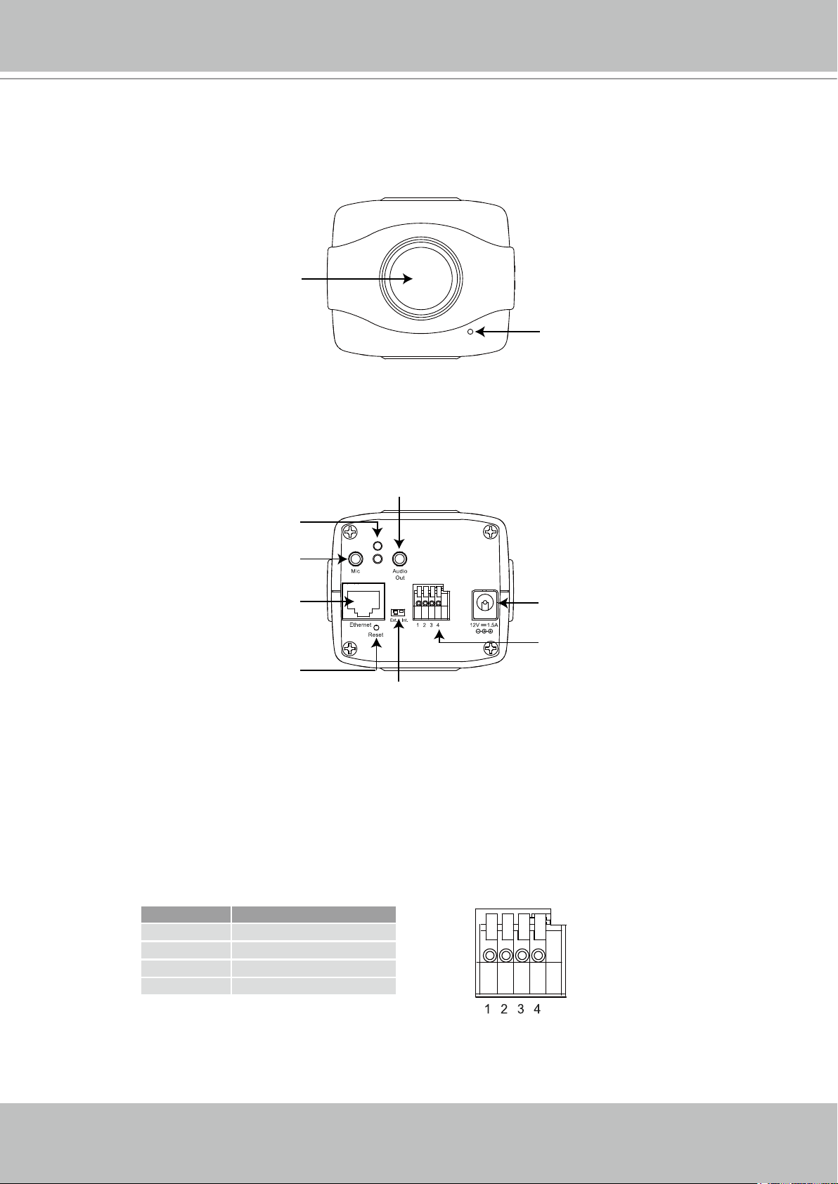
Physical Description
Front Panel
Lens
Back Panel
Built-in Microphone
Audio Out
Status LED
Microphone In
Ethernet 10/100
RJ45 Socket
Indented Reset
Button
External/Internal MIC Switch
Power Cord Socket
General I/O
Terminal Block
General I/O Terminal Block
This Network Camera provides a general I/O terminal block which is used to connect external
input / output devices. The pin denitions are described below.
Pin Name
1 Power +12V
2 Digital Output
3 Digital Input
4 Ground
Page 5
VIVOTEK - A Leading Provider of Multimedia Communication Solutions
User's Manual - 5
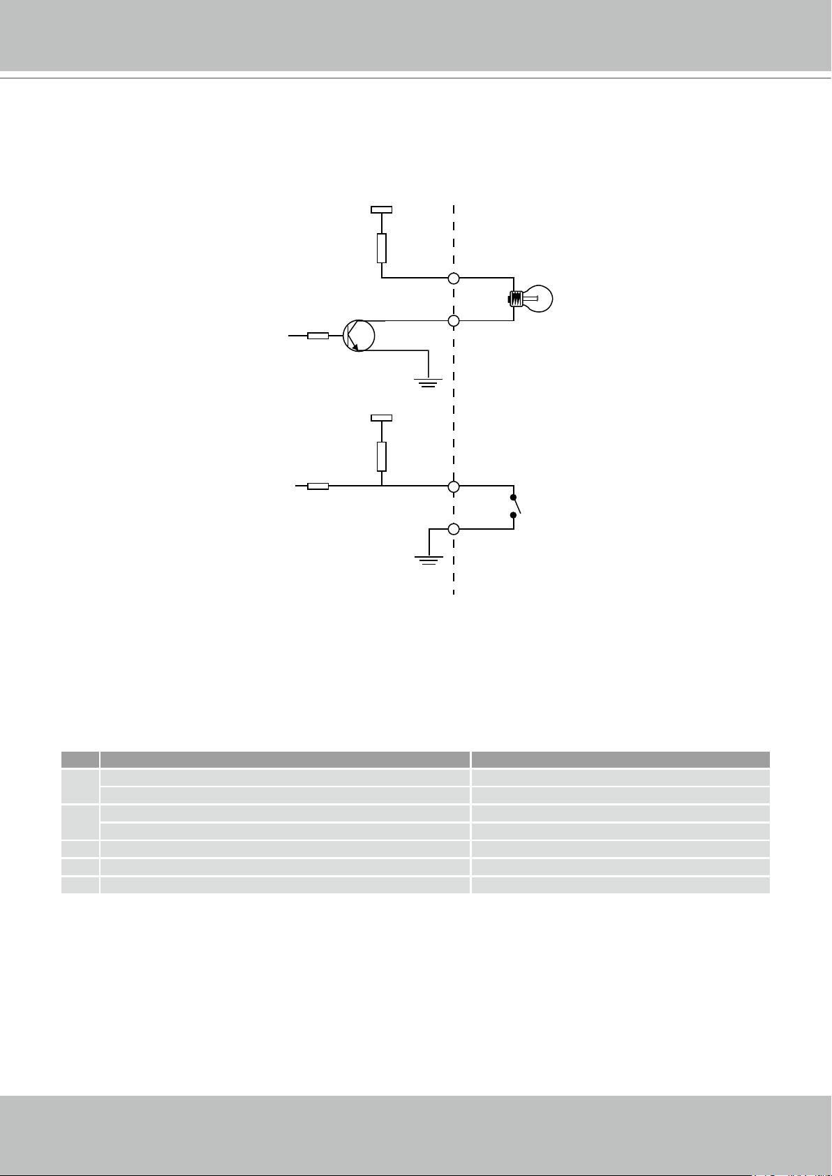
12V
+12V
Digital output
PIN 1
Power+12V
PIN 2
Digital input
PIN 3
Ground
PIN 4
DI/DO Diagram
Please refer to the following illustration for the connection method�
Status LED
The LED indicates the status of the Network Camera�
Item LED status Description
Steady Red Power on and system booting
1
Red LED unlighted Power off
Steady Red + Blink Green every 1 sec� Network works (heartbeat)
2
Steady Red + Green LED unlighted Network fail
3 Steady Red + Blink Green every 2 sec� Audio mute (heartbeat)
4 Blink Red every 0�15 sec� + Blink Green every 1 sec� Upgrading firmware
5 Blink Red every 0�15 sec� + Blink Green every 0�15 sec� Restore default
Page 6
VIVOTEK - A Leading Provider of Multimedia Communication Solutions
6 - User's Manual
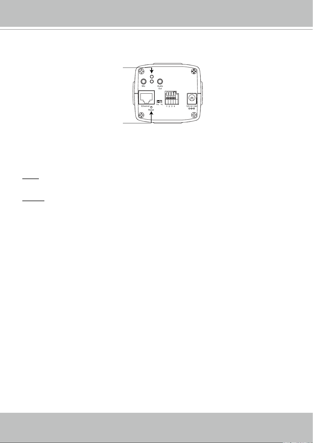
Hardware Reset
Status LED
Indented Reset
Button
The reset button is used to reset the system or restore the factory default settings� Sometimes
resetting the system can return the camera to normal operation� If the system problems remain
after reset, restore the factory settings and install again.
Reset: Press and release the indented reset button with a paper clip or thin object� Wait for the
Network Camera to reboot�
Restore: Press and hold the reset button until the status LED rapidly blinks� It takes about 30
seconds. Note that all settings will be restored to factory default. Upon successful restore, the
status LED will blink green and red during normal operation�
Page 7
VIVOTEK - A Leading Provider of Multimedia Communication Solutions
User's Manual - 7
IP address : 192.168.0.3
Subnet mask : 255.255.255.0
Default router : 192.168.0.1
IP address : 192.168.0.2
Subnet mask : 255.255.255.0
Default router : 192.168.0.1
LAN (Local Area Network)
Router IP address : 192.168.0.1
WAN (Wide Area Network )
Router IP address : from ISP
Cable or DSL Modem
POWER
COLLISION
LINK
RECEIVE
PARTITION
1
2
3
4
5
Internet
1
2
3
POWE R
COLLISION
LINK
RECEI VE
PARTITI ON
1
2
3
4
5
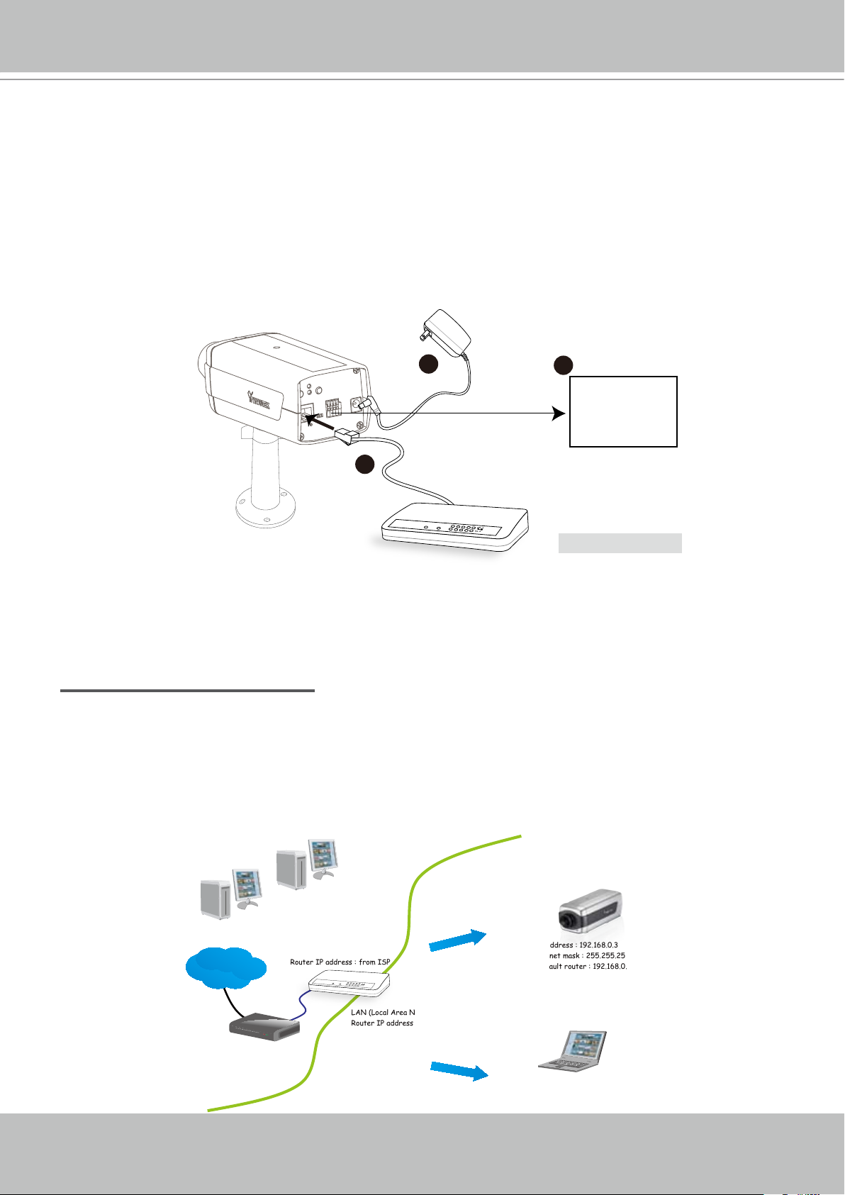
Network Deployment
Setting up the Network Camera over the Internet
This section explains how to congure the Network Camera over an Internet connection�
1. If you have external devices such as sensors and alarms, make the connection from the
general I/O terminal block.
2� Connect the camera to a switch via Ethernet cable�
3� Connect the supplied power cable from the Network Camera to a power outlet�
1:Power +12V
2:Digital output
3:Digital input
4:Ground
Ethernet Switch
There are several ways to set up the Network Camera over the Internet� The rst way is to set
up the Network Camera behind a router� The second way is to utilize a static IP� The third way is
to use PPPoE�
Internet connection via a router
Before setting up the Network Camera over the Internet, make sure you have a router and follow
the steps below�
1. Connect your Network Camera behind a router, the Internet environment is illustrated below.
Regarding how to obtain your IP address, please refer to Software Installation on page 10 for
details�
Page 8

VIVOTEK - A Leading Provider of Multimedia Communication Solutions
8 - User's Manual
2. In this case, if the Local Area Network (LAN) IP address of your Network Camera is
192.168.0.3, please forward the following ports for the Network Camera on the router.
■ HTTP port
■ RTSP port
■ RTP port for audio
■ RTCP port for audio
■ RTP port for video
■ RTCP port for video
If you have changed the port numbers on the Network page, please open the ports accordingly
on your router. For information on how to forward ports on the router, please refer to your
router’s user’s manual�
3� Find out the public IP address of your router provided by your ISP (Internet Service Provider)�
Use the public IP and the secondary HTTP port to access the Network Camera from the
Internet� Please refer to Network Type on page 32 for details�
Internet connection with static IP
Choose this connection type if you are required to use a static IP for the Network Camera�
Please refer to LAN on page 32 for details�
Internet connection via PPPoE (Point-to-Point over Ethernet)
Choose this connection type if you are connected to the Internet via a DSL Line� Please refer to
PPPoE on page 33 for details�
Page 9
VIVOTEK - A Leading Provider of Multimedia Communication Solutions
User's Manual - 9
POWER
COLLISION
LINK
RECEIV E
PARTITION
1
2
3
4
5
POWER
COLLISION
LINK
RECEIVE
PARTITION
1
2
3
4
5
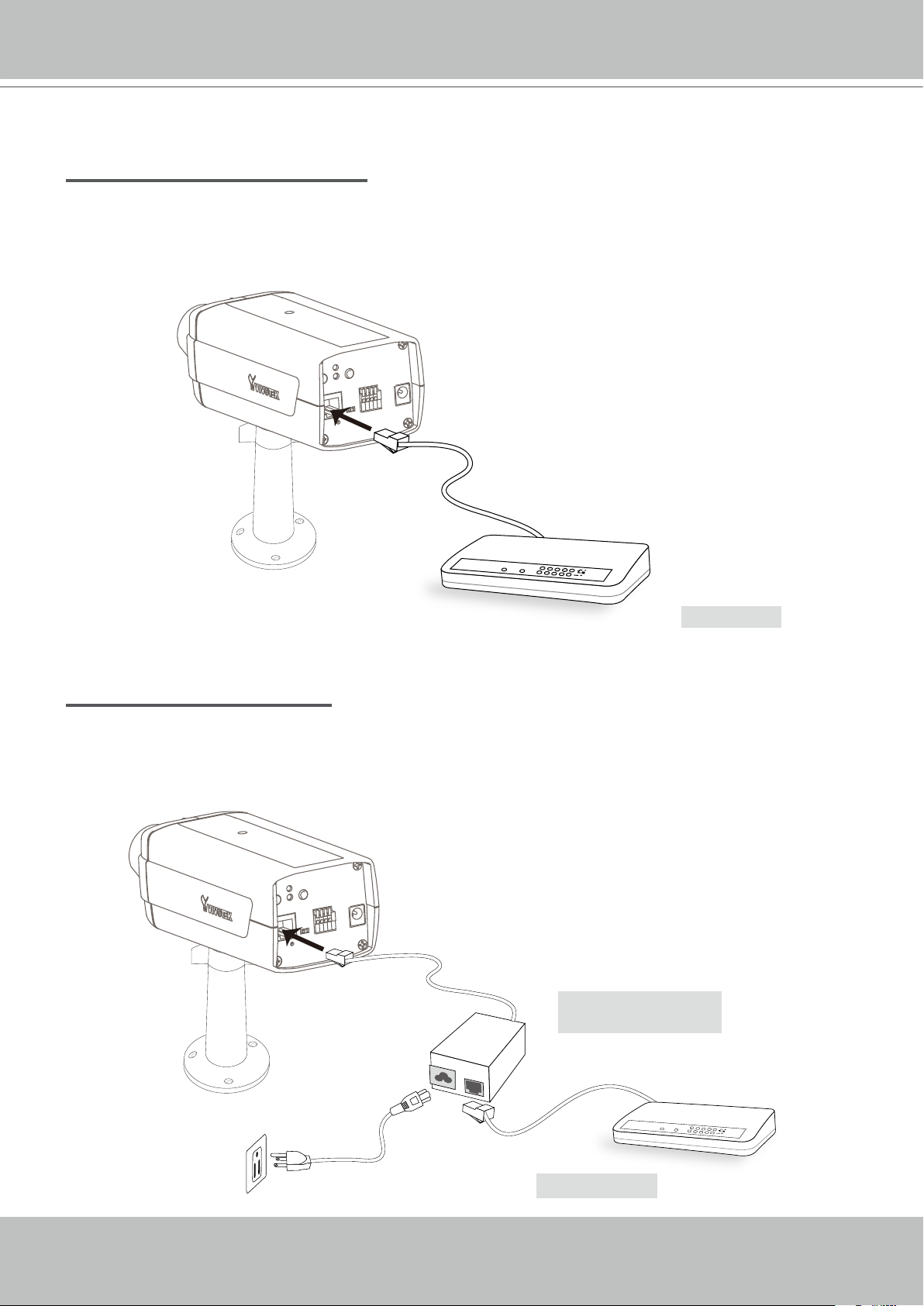
Set up the Network Camera through Power over Ethernet (PoE)
When using a PoE-enabled switch
The Network Camera is PoE-compliant, which allows it to be powered via a single Ethernet
cable� If your switch/router supports PoE, refer to the following illustration to connect the
Network Camera to a PoE-enabled switch/router.
power + data transmission
PoE Switch
When using a non-PoE switch
If your switch/router does not support PoE, use a PoE power injector (optional) to connect the
Network Camera and a non-PoE switch/router.
PoE Power Injector
(optional)
Non-PoE Switch
Page 10
VIVOTEK - A Leading Provider of Multimedia Communication Solutions
10 - User's Manual
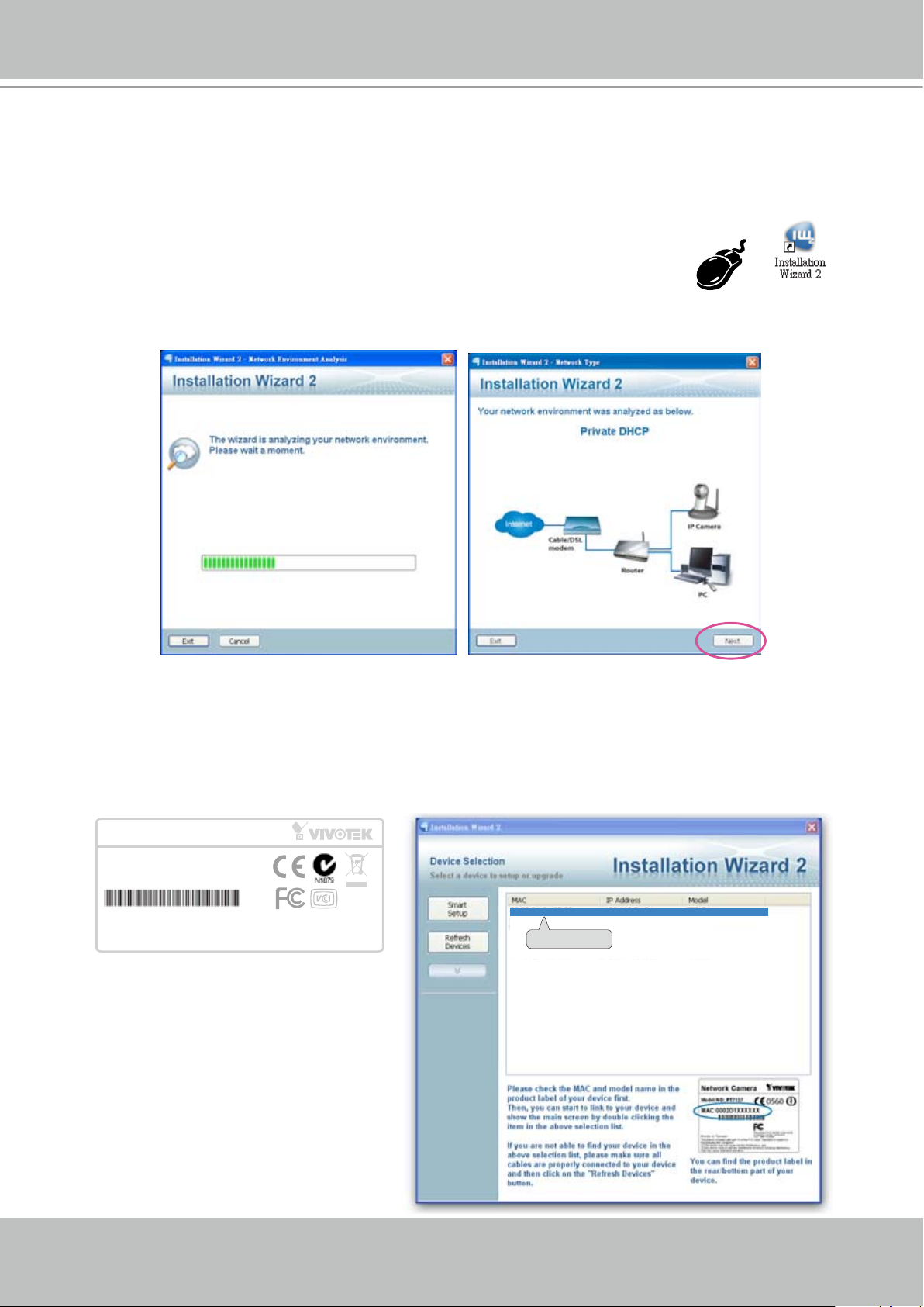
0002D1730202
00-02-D1-73-02-02 192.168.5.151 IP7130
Network Camera
Model No: IP7130
Made in Taiwan
This device complies with part 15 of the FCC rules. Operation is subject to the following two conditions:
(1)This device may not cause harmful interference, and
(2) this device must accept any interference received, including interference that may cause undesired operation.
Pat. 6,930,709
MAC:0002D1730202
R o H S
Software Installation
Installation Wizard 2 (IW2), free-bundled software included on the product CD, helps you set up
your Network Camera on the LAN�
1� Install IW2 from the Software Utility directory on the software CD�
Double click the IW2 shortcut on your desktop to launch the program�
2� The program will conduct an analysis of your network environment�
After your network environment is analyzed, please click Next to continue the program�
3� The program will search for all VIVOTEK network devices on the same LAN�
4. After searching, the main installer window will pop up. Click on the MAC and model name
which matches the product label on your device to connect to the Network Camera via
Internet Explorer�
Page 11
VIVOTEK - A Leading Provider of Multimedia Communication Solutions
User's Manual - 11
Ready to Use
1� Access the Network Camera from the LAN�
2� Retrieve live video through a web browser or recording software�
Page 12
VIVOTEK - A Leading Provider of Multimedia Communication Solutions
12 - User's Manual
Accessing the Network Camera
This chapter explains how to access the Network Camera through web browsers, RTSP players,
3GPP-compatible mobile devices, and VIVOTEK recording software.
Using Web Browsers
Use Installation Wizard 2 (IW2) to access to the Network Cameras installed on the LAN.
If your network environment is not a LAN, follow these steps to access the Network Camera:
1� Launch your web browser (ex� Microsoft
2. Enter the IP address of the Network Camera in the address eld. Press Enter�
3� The live video will be displayed in your web browser�
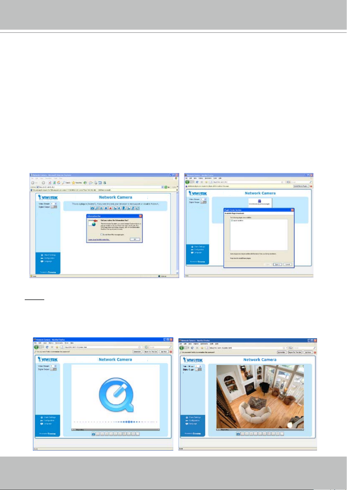
4. If this is the rst time installing the VIVOTEK network camera, an information bar will pop up
as shown below� Follow the instructions to install the required plug-in on your computer�
®
Internet Explorer, Mozilla Firefox, or Netscape).
NOTE
► For Mozilla Firefox or Netscape users, your browser will use Quick Time to stream the live
video. If you donn’t have Quick Time on your computer, please install it rst, then launch the
web browser�
Page 13
VIVOTEK - A Leading Provider of Multimedia Communication Solutions
User's Manual - 13
► By default, the Network Camera is not password-protected. To prevent unauthorized access,
it is highly recommended to set a password for the Network Camera� For more information
about how to enable password protection, please refer to Security on page 26�
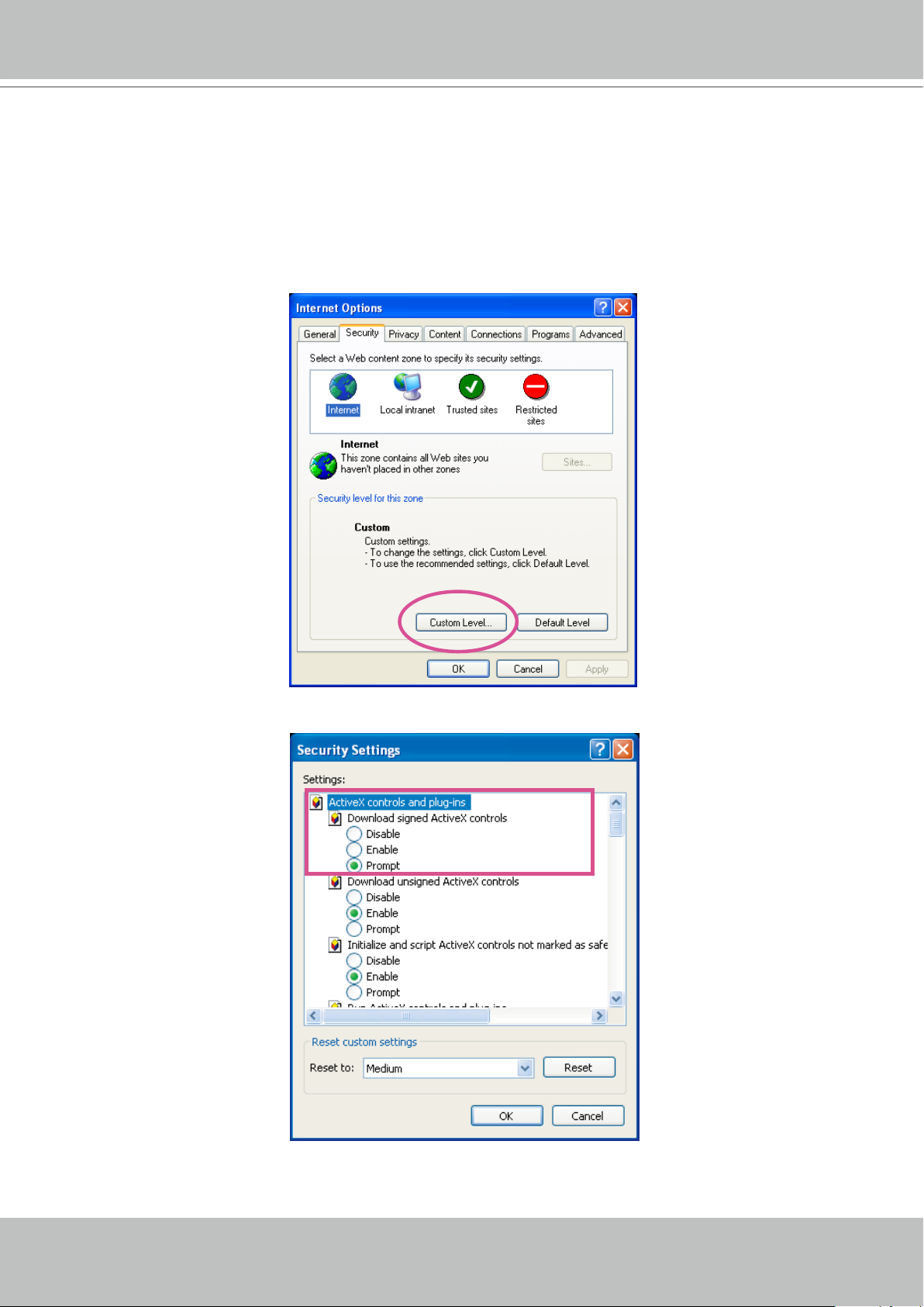
► If you see a dialog box indicating that your security settings prohibit running ActiveX
®
Controls, please enable the ActiveX
Controls for your browser�
®
1� Choose Tools > Internet Options > Security > Custom Level�
2. Look for Download signed ActiveX
®
controls; select Enable or Prompt� Click OK�
3. Refresh your web browser, then install the Active X® control� Follow the instructions to
complete installation�
Page 14
VIVOTEK - A Leading Provider of Multimedia Communication Solutions
14 - User's Manual
rtsp://192.168.5.151:554/live.sdp
Video 16:38:01 2008/01/03
Using RTSP Players
To view the MPEG-4 streaming media using RTSP players, you can use one of the following
applications that support RTSP streaming�
Quick Time Player
Real Player
VLC media player
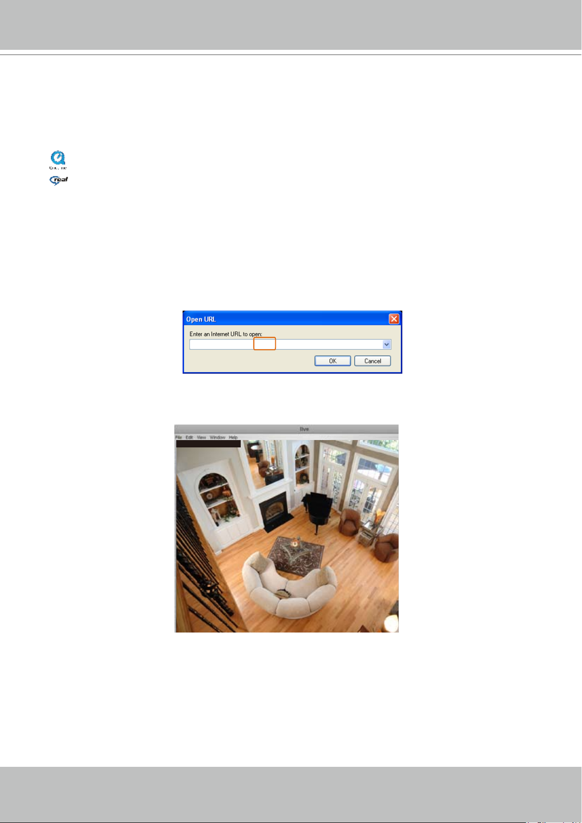
1� Launch the RTSP player�
mpegable Player
2� Choose File > Open URL� A URL dialog box will pop up�
3. The address format is rtsp://<ip address>:<rtsp port>/<RTSP streaming access name for
pvPlayer
stream1 or stream2>
As most ISPs and players only allow RTSP streaming through port number 554, please set the
RTSP port to 554. For more information, please refer to RTSP Streaming on page 41�
For example:
4� The live video will be displayed in your player�
For more information on how to configure the RTSP access name, please refer to RTSP
Streaming on page 41 for more details�
Page 15
VIVOTEK - A Leading Provider of Multimedia Communication Solutions
User's Manual - 15
Video Mode MPEG-4
Frame size 176 x 144
Maximum frame rate 5 fps
Intra frame period 1S
Video quality (Constant bit rate) 40kbps
Audio type (GSM-AMR) 12.2kbps
rtsp://192.168.5.151:554/live.sdp
Using 3GPP-compatible Mobile Devices
To view the streaming media through 3GPP-compatible mobile devices, make sure the Network
Camera can be accessed over the Internet� For more information on how to set up the Network
Camera over the Internet, please refer to Setting up the Network Camera over the Internet on
page 7�
To utilize this feature, please check the following settings on your Network Camera:
1. Because most players on 3GPP mobile phones do not support RTSP authentication, make
sure the authentication mode of RTSP streaming is set to disable�
For more information, please refer to RTSP Streaming on page 41�
2. As the the bandwidth on 3G networks is limited, larger video sizes are not available. Please
set the video and audio streaming parameters as listed below�
For more information, please refer to Audio and Video on page 48�
3. As most ISPs and players only allow RTSP streaming through port number 554, please set
the RTSP port to 554. For more information, please refer to RTSP Streaming on page 41�
4� Launch the player on the 3GPP-compatible mobile device (ex� Real Player)�
5� Type the following URL command into the player�
The address format is rtsp://<public ip address of your camera>:<rtsp port>/<RTSP streaming
access name for stream1 or stream2>�
For example:
Page 16
VIVOTEK - A Leading Provider of Multimedia Communication Solutions
16 - User's Manual
Using VIVOTEK Recording Software
The product software CD also contains VIVOTEK’s recording software, allowing simultaneous
monitoring and video recording for multiple Network Cameras� Please install the recording
software, then launch the program to add the Network Camera to the Channel list. For detailed
information about how to use the recording software, please refer to the user’s manual of the
software or download the manual from http://www.vivotek.com�
Page 17
VIVOTEK - A Leading Provider of Multimedia Communication Solutions
User's Manual - 17
VIVOTEK INC. Logo
Live View Window
Camera Control Area
Configuration Area
Host Name
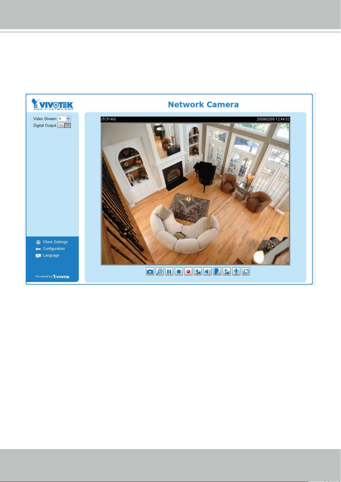
Main Page
This chapter explains the layout of the main page� It is composed of the following sections:
VIVOTEK INC. Logo, Host Name, Camera Control Area, Configuration Area, Menu, and Live
Video Window�
VIVOTEK INC. Logo
Click this logo to visit the VIVOTEK website�
Host Name
The host name can be customized to t your needs. For more information,
24�
Camera Control Area
Video Stream: This Network Cmera supports MJPEG or MPEG-4 dual streams simultaneously� You can
select either one for live viewing�
Digital Output: Click to turn the digital output device on or off�
Conguration Area
Client Settings: Click this button to access the client setting page. For more information, please refer to
Client Settings on page 21�
Conguration: Click this button to access the conguration page of the Network Camera. It is suggested
that a password be applied to the Network Camera so that only the administrator can configure the
Network Camera. For more information, please refer to Conguration on page 23�
please refer to
System on page
Language: Click this button to choose a language for the user interface� Language options are available
in: English, Deutsch, Español, Français, Italiano,
日本語
, Português,
簡体中文
繁體中文
and
�
Page 18
VIVOTEK - A Leading Provider of Multimedia Communication Solutions
18 - User's Manual
Video and Audio Control Buttons
MPEG-4 Protocol and Media Options
Video Title
Time
Title and Time
Video 17:08:56 2008/06/25
Live Video Window
■ The following window is displayed when the video mode is set to MPEG-4:
Video Title: The video title can be congured. For more information, please refer to Video Settings on
page 48�
MPEG-4 Protocol and Media Options: The transmission protocol and media options for MPEG-4 video
streaming. For further conguration, please refer to Client Settings on page 21�
Time: Display the current time. For further conguration, please refer to Video Settings on page 48�
Title and Time: The video title and time can be stamped on the streaming video. For further conguration,
please refer to Video Settings on page 48�
Video and Audio Control Buttons: Depending on the Network Camera model and Network Camera
conguration, some buttons may not be available.
Snapshot: Click this button to capture and save still images� The captured images will be displayed
in a pop-up window� Right-click the image and choose Save Picture As to save it in JPEG (*�jpg) or BMP
(*�bmp) format�
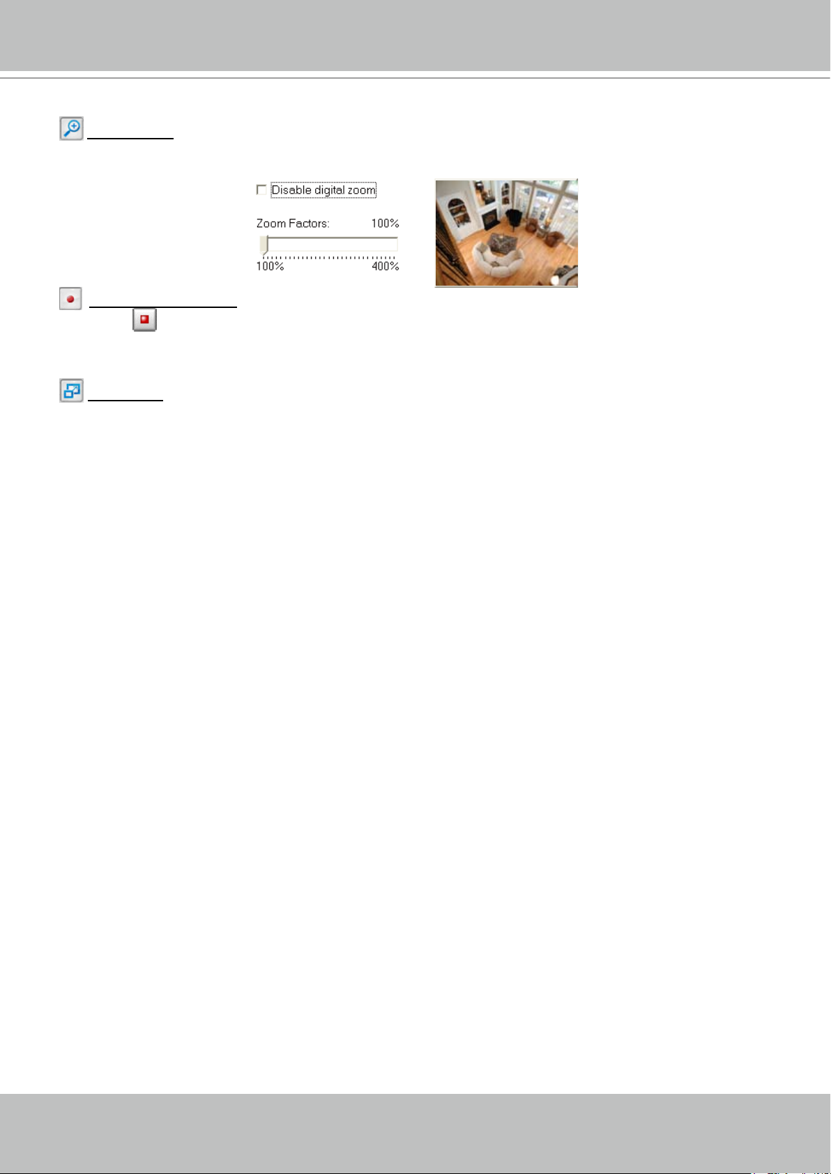
Digital Zoom: Click and uncheck “Disable digital zoom” to enable the zoom operation. The navigation
screen indicates the part of the image being magnied. To control the zoom level, drag the slider bar. To
move to a different area you want to magnify, drag the navigation screen image.
after clicking the Pause button�
transmission�
Stop MP4 Recording button to end recording. When you exit the web browser, video recording stops
accordingly. To specify the storage destination and le name, please refer to MP4 Saving Options on
page 22 for details�
Pause: Pause the transmission of the streaming media� The button becomes the Resume button
Stop: Stop the transmission of the streaming media� Click the Resume button to continue
Start MP4 Recording: Click this button to record video clips in MP4 file format� Press the
Page 19
VIVOTEK - A Leading Provider of Multimedia Communication Solutions
User's Manual - 19
Time
Video Title
Title and Time
Video Control Buttons
Video 13:44:17 2008/06/30
Volume: If the Mute function is not activated, move the slider bar to adjust the volume on the
local computer�
Mute: Turn off the volume on the local computer� The button becomes the Audio On button after
clicking the Mute button�
Talk: Click this button to talk to people around the Network Camera� Audio will project from
the external speaker connected to the Network Camera� Click this button
again to end talking
transmission�
Mic Volume: When the Mute function is not activated, move the slider bar to adjust the
microphone volume on the local computer�
Mute: Turn off the Mic volume on the local computer� The button becomes the Mic On button
after clicking the Mute button�
Full Screen: Click this button to switch to full screen mode. Press the “Esc” key to switch back to normal
mode�
■ The following window is displayed when the video mode is set to MJPEG:
Video Title: The video title can be congured. For more information, please refer to Video Settings on
page 48�
Time: Display the current time. For more information, please refer to
Title and Time: Video title and time can be stamped on the streaming video. For more information, please
refer to
Video Settings on page 48�
Video and Audio Control Buttons: Depending on the Network Camera model and Network Camera
conguration, some buttons may not be available.
Video Settings on page 48�
in a pop-up window� Right-click the image and choose Save Picture As to save it in JPEG (*�jpg) or BMP
(*�bmp) format�
Snapshot: Click this button to capture and save still images� The captured images will be displayed
Page 20
VIVOTEK - A Leading Provider of Multimedia Communication Solutions
20 - User's Manual
Digital Zoom: Click and uncheck “Disable digital zoom” to enable the zoom operation. The navigation
screen indicates the part of the image being magnied. To control the zoom level, drag the slider bar. To
move to a different area you want to magnify, drag the navigation screen.
Start MP4 Recording: Click this button to record video clips in MP4 file format to your computer�
Press the
Stop MP4 Recording button to end recording. When you exit the web browser, video
recording stops accordingly. To specify the storage destination and le name, please refer to MP4 Saving
Options on page 22 for details�
Full Screen: Click this button to switch to full screen mode. Press the “Esc” key to switch back to normal
mode�
Page 21
VIVOTEK - A Leading Provider of Multimedia Communication Solutions
User's Manual - 21
Client Settings
This chapter explains how to select the stream transmission mode and saving options on the
local computer. When nished with the settings on this page, click Save on the page bottom to
enable the settings�
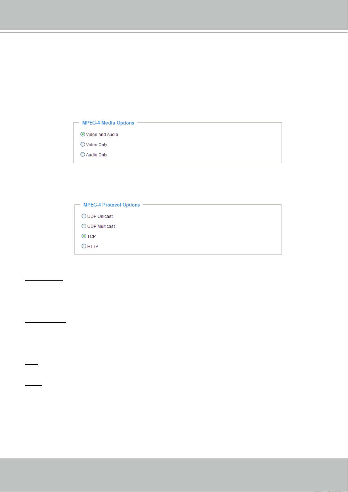
MPEG-4 Media Options
Select to stream video or audio data or both� This is enabled only when the video mode is set to MPEG-4�
MPEG-4 Protocol Options
Depending on your network environment, there are four transmission modes for MPEG-4 streaming:
UDP unicast: This protocol allows for better real-time audio and video streams. However, network
packets may be lost due to network burst trafc and images may be broken. Activate the UDP connection
when occasions require time-sensitive responses and the video quality is less important� Note that each
unicast client connecting to the server takes up additional bandwidth and the Network Camera allows up
to ten simultaneous accesses�
UDP multicast: This protocol allows multicast-enabled routers to forward network packets to all clients
requesting streaming media� This helps to reduce the network transmission load of the Network Camera
while serving multiple clients at the same time. Note that to utilize this feature, the Network Camera must
be configured to enable multicast streaming at the same time. For more information, please refer to
RTSP Streaming on page 41�
TCP: This protocol guarantees the complete delivery of streaming data and thus provides better video
quality� The downside of this protocol is that its real-time effect is not as good as that of the UDP protocol�
HTTP: This protocol allows for the same transmission quality as the TCP protocol without needing to
open specic ports for streaming under some network environments. Users inside a rewall can utilize
this protocol to allow streaming data through�
Page 22
VIVOTEK - A Leading Provider of Multimedia Communication Solutions
22 - User's Manual
CLIP_20080108-180853
Date and time suffix
The format is: YYYYMMDD_HHMMSS
File name prefix
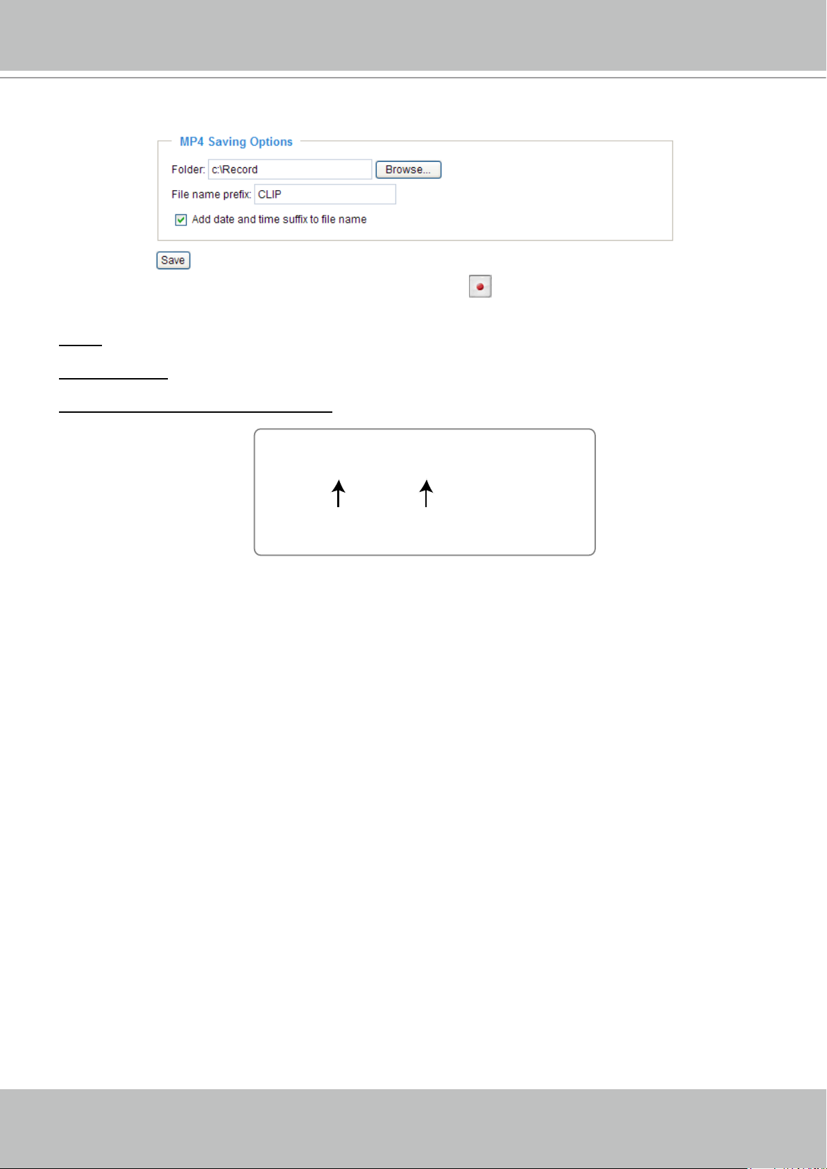
MP4 Saving Options
Users can record live video as they are watching by clicking Start MP4 Recording on the main page�
Here, you can specify the storage destination and le name.
Folder: Specify the storage destination for the recorded video les.
File name prex: Enter the text that will be appended to the front of the video le name.
Add date and time sufx to the le name: Select this option to append the date and time to the end of the
le name.
Page 23
VIVOTEK - A Leading Provider of Multimedia Communication Solutions
User's Manual - 23
Click to switch to Advanced Mode
Firmware Version
Configuration List
Conguration
Click Configuration on the main page to enter the camera setting pages� Note that only
Administrators can access the conguration page.
VIVOTEK offers an easy-to-use user interface that helps you set up your network camera with
minimal effort. To simplify the setting procedure, two types of user interfaces are available:
Advanced Mode for professional users and Basic Mode for entry-level users� Some advanced
functions (HTTPS/ Access list/ Homepage layout/ Application/ Recording/ System log/ View
parameters) are not displayed in Basic Mode�
If you want to set up advanced functions, please click [Advanced Mode] on the bottom of the
conguration list to quickly switch to Advanced Mode.
In order to simplify the user interface, the detailed information will be hidden unless you click on
the function item. When you click on the rst sub-item, the detailed information for the rst subitem will be displayed; when you click on the second sub-item, the detailed information for the
second sub-item will be displayed and that of the rst sub-item will be hidden.
The following is the user interface of the Basic Mode and the Advanced Mode:
Basic Mode
Page 24
VIVOTEK - A Leading Provider of Multimedia Communication Solutions
24 - User's Manual
Configuration List
Firmware Version
Click to switch to Basic Mode
Advanced Mode
Each function on the conguration list will be explained in the following sections. Those functions that are
displayed only in Advanced Mode are marked with
Advanced Mode
� If you want to set up advanced
functions, please click [Advanced Mode] on the bottom of the conguration list to quickly switch over.
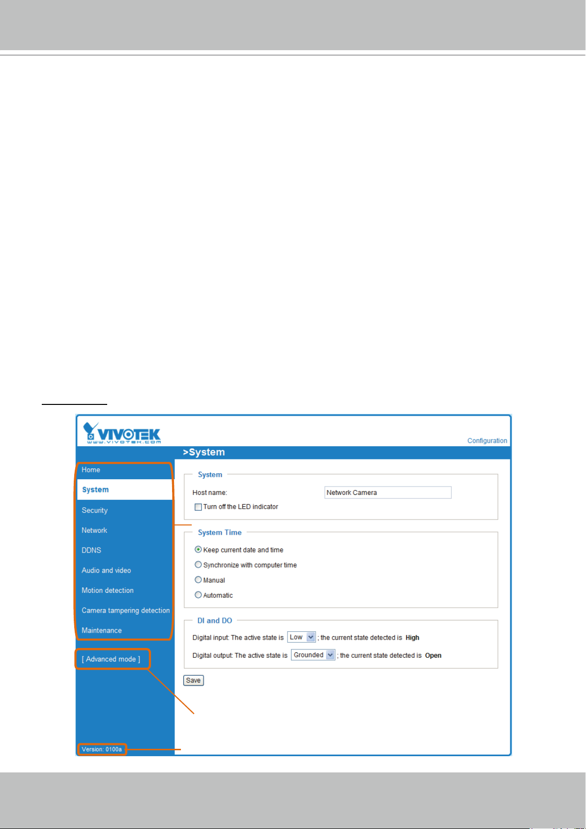
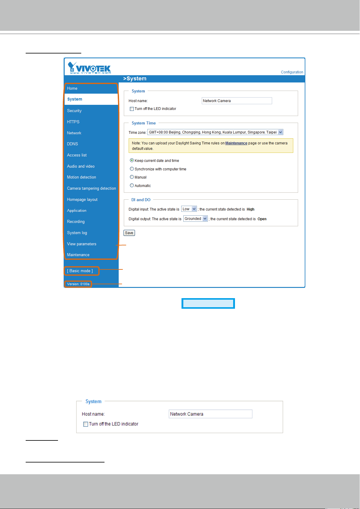
System
This section explains how to congure the basic settings for the Network Camera, such as the
host name and system time. It is composed of the following three columns: System, System
Time and DI and DO. When nished with the settings on this page, click Save at the bottom of
the page to enable the settings�
System
Host name: Enter the desired name for the Network Camera� The text will be displayed at the top of the
main page�
Turn off the LED indicators: If you do not want to let others know that the network camera is in operation,
you can select this option to turn off the LED indicators�
Page 25
VIVOTEK - A Leading Provider of Multimedia Communication Solutions
User's Manual - 25
System Time
Keep current date and time: Select this option to preserve the current date and time of the Network
Camera� The Network Camera’s internal real-time clock maintains the date and time even when the
system power is turned off�
Sync with computer time: Select this option to synchronize the date and time of the Network Camera with
the local computer� The read-only date and time of the PC is displayed when updated�
Manual: The administrator can enter the date and time manually� Note that the date and time format are
[yyyy/mm/dd] and [hh:mm:ss].
Automatic: The Network Time Protocol is a protocol which synchronizes computer clocks by periodically
querying an NTP Server�
NTP server: Assign the IP address or domain name of the time-server� Leaving the text box blank
connects the Network Camera to the default time servers�
Update interval: Select to update the time using the NTP server on an hourly, daily, weekly, or monthly
basis�
Time zone
Advanced Mode
: Select the appropriate time zone from the list. If you want to upload
Daylight Savings Time rules on the Maintenance page, please refer to Upload / Export Daylight Saving
Time Conguration File on page 80 for details�
DI and DO
Digital input: Select High or Low to dene the normal status for the digital input. The Network Camera will
report the current status�
Digital output: Select Grounded or Open to dene the normal status for the digital output. The Network
Camera will show whether the trigger is activated or not�
Page 26
VIVOTEK - A Leading Provider of Multimedia Communication Solutions
26 - User's Manual
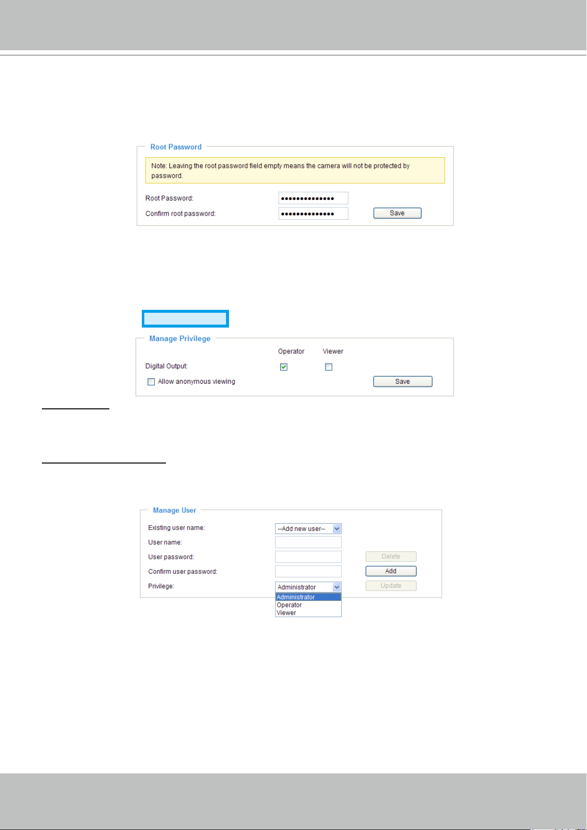
Security
This section explains how to enable password protection and create multiple accounts�
Root Password
The administrator account name is “root”, which is permanent and can not be deleted. If you want to add
more accounts in the Manage User section, please set the password for the “root” account rst.
1. Type the password in both text boxes, then click Save to enable password protection�
2� A window will be prompted for authentication; type the correct user’s name and password in their
respective elds to access the Network Camera.
Manage Privilege
Digital Output: You can modify the management privileges of operators or viewers� Check or uncheck
the desired items, then click Save to enable the settings. If you give Viewers the privilege, Operators will
also have the ability to control the Network Camera through the main page� (Please refer to Main Page
on page 17�)
Allow anonymous viewing: If you check this item, any client can access the live stream without entering a
User ID and Password�
Advanced Mode
Manage User
Administrators can add up to 20 user accounts�
1� Input the new user’s name and password�
2� Select the privilege level for the new user account� Click Add to enable the setting�
Access rights are sorted by user privilege (Administrator, Operator, and Viewer). Only administrators can
access the Conguration page. Though operators cannot access the Conguration page, they can use
the URL Commands to get and set the value of parameters. For more information, please refer to URL
Commands of the Network Camera on page 83� Viewers access only the main page for live viewing�
You can also change a user’s access rights or delete user accounts�
1� Select an existing account to modify�
2� Make necessary changes and click Update or Delete to enable the setting�
Page 27
VIVOTEK - A Leading Provider of Multimedia Communication Solutions
User's Manual - 27
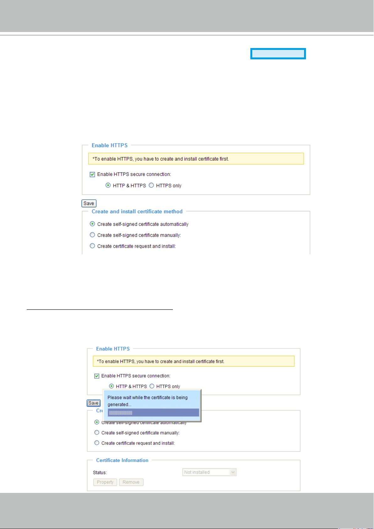
HTTPS (Hypertext Transfer Protocol over SSL)
Advanced Mode
This section explains how to enable authentication and encrypted communication over SSL
(Secure Socket Layer)� It helps protect streaming data transmission over the Internet on higher
security level�
Enable HTTPS
Check this item to enable HTTPS communication, then select a connection option: "HTTP & HTTPS"
or "HTTPS only". Note that you have to create and install a certicate rst in the second section before
clicking the Save button�
Create and Install Certicate Method
Before using HTTPS for communication with the Network Camera, a Certicate must be created rst.
There are three ways to create and install a certicate:
Create a self-signed certificate automatically
1� Select this option�
2. In the rst section, check Enable HTTPS secure connection, then select a connection option: “HTTP
& HTTPS” or “HTTPS only”.
3� Click Save to generate a certicate.
Page 28
VIVOTEK - A Leading Provider of Multimedia Communication Solutions
28 - User's Manual
https://192.168.5.151/index.html
https://
4. The Certicate Information will automatically de displayed in the third section as shown below. You can
click Property to view detailed information about the certicate.
5� Click Home to return to the main page� Change the address from “http://” to “https://“ in the address
bar and press Enter on your keyboard� A Security Alert dialog box will pop up� Click OK or Yes to enable HTTPS�
Page 29
VIVOTEK - A Leading Provider of Multimedia Communication Solutions
User's Manual - 29
Create a self-signed certificate manually
1� Select this option�
2� Click Create to open the Create Certicate page, then click Save to generate the certicate.
3. The Certicate Information will automatically be displayed in the third column as shown below. You
can click Property to see detailed information about the certicate.
Create a certificate and install : Select this option if you want to create a certicate from a certi-
cate authority�
1� Select this option�
2� Click Create to open the Create Certicate page, then click Save to generate the certicate.
Page 30
VIVOTEK - A Leading Provider of Multimedia Communication Solutions
30 - User's Manual
3. If you see the following Information bar, click OK and click on the Information bar at the top of the page
to allow pop-ups�
4. The pop-up window shows an example of a certicate request.
Page 31

VIVOTEK - A Leading Provider of Multimedia Communication Solutions
User's Manual - 31
5� Look for a trusted certificate authority that issues digital certificates� Enroll the Network Camera�
Wait for the certicate authority to issue an SSL certicate; click Browse... to search for the issued
certicate, then click Upload in the second section.
NOTE
► How do I cancel the HTTPS settings?
1� Uncheck Enable HTTPS secure connection in the rst column and click Save; a warning dialog box
will pop up�
2� Click OK to disable HTTPS�
3� The webpage will redirect to a non-HTTPS page automatically�
► If you want to create and install other certicates, please remove any existing ones. To remove the
signed certicates, uncheck Enable HTTPS secure connection in the rst section and click Save�
Then click Remove to erase the certicate.
Page 32

VIVOTEK - A Leading Provider of Multimedia Communication Solutions
32 - User's Manual
Network
This section explains how to congure a wired network connection for the Network Camera.
Network Type
LAN
Select this option when the Network Camera is deployed on a local area network (LAN) and is intended
to be accessed by local computers� The default setting for the Network Type is LAN� Rememer to click
Save when you complete the Network setting�
Get IP address automatically: Select this option to obtain an available dynamic IP address assigned by
the DHCP server each time the camera is connected to the LAN�
Use xed IP address: Select this option to manually assign a static IP address to the Network Camera�
1. You can make use of VIVOTEK Installation Wizard 2 on the software CD to easily set up the Network
Camera on the LAN� Please refer to Software Installation on page 10 for details�
2. Enter the Static IP, Subnet mask, Default router, and Primary DNS provided by your ISP.
TM
Enable UPnP presentation: Select this option to enable UPnP
presentation for your Network Camera
so that whenever a Network Camera is connected to the LAN, shortcuts to those Network Cameras
will be listed in My Network Places� You can then click the shortcut to go directly to the web browser�
Currently, UPnP
TM
is supported by Windows XP and Vista. Note that to utilize this feature, the UPnPTM
component must be installed on your computer�
Page 33

VIVOTEK - A Leading Provider of Multimedia Communication Solutions
User's Manual - 33
Network Camera (192.168.5.151)
Enable UPnP port forwarding: To access the Network Camera from the Internet, select this option to
allow the Network Camera to open ports on the router automatically so that video streams can be sent
from the LAN. To utilize this feature, make sure that your router supports UPnP
TM
and it is activated�
PPPoE (Point-to-point over Ethernet)
Select this option to configure your Network Camera to make it accessible from anywhere with an
Internet connection. Note that to utilize this feature, it requires an account provided by your ISP.
Follow the steps below to acquire your Network Camera’s public IP address�
1� Set up the Network Camera on the LAN�
2. Go to Home > Conguration > Application > Server Settings (please refer to Server Settings on page
67) to add a new email or FTP server�
3. Go to Conguration > Application > Media Settings (please refer to Media Settings on page 70)� Select
System log so that you will receive the system logs in TXT file format which contains the Network
Camera’s public IP address on your email or FTP server�
4. Go to Conguration > Network > Network Type. Select PPPoE and enter the user name and password
provided by your ISP� Click Save to enable the setting�
5� The Network Camera will reboot�
6� Disconnect the power to the Network Camera; move it from the LAN environment�
NOTE
► If the default ports are already used by other devices connected to the same router, the Network
Camera will select other ports for the Network Camera�
TM
► If UPnP
is not supported by your router, you will see the following message:
Error: Router does not support UPnP port forwarding.
Page 34

VIVOTEK - A Leading Provider of Multimedia Communication Solutions
34 - User's Manual
► Steps to enable the UPnPTM user interface on your computer:
Note that you must log on to the computer as a system administrator to install the UPnP
components�
1. Go to Start, click Control Panel, then click Add or Remove Programs�
2. In the Add or Remove Programs dialog box, click Add/Remove Windows Components�
TM
3�
In the Windows Components Wizard dialog box, select Networking Services and click Details�
Page 35

VIVOTEK - A Leading Provider of Multimedia Communication Solutions
User's Manual - 35
From the Internet LAN
http://203.67.124.123:8080 http://192.168.4.160 or
http://192.168.4.160:8080
4. In the Networking Services dialog box, select Universal Plug and Play and click OK�
5� Click Next in the following window�
TM
6� Click Finish� UPnP
► How does UPnP
UPnP
TM
networking technology provides automatic IP conguration and dynamic discovery of devices
TM
is enabled�
work?
added to a network. Services and capabilities offered by networked devices, such as printing and le
sharing, are available to each other without the need for cumbersome network conguration. In the
case of Network Cameras, you will see Network Camera shortcuts under My Network Places.
► Enabling UPnP port forwarding allows the Network Camera to open a secondary HTTP port on the
router-not HTTP port-meaning that you will need to add the secondary HTTP port number to the
Network Camera’s public address in order to access the Network Camera from the Internet� For
example, when the HTTP port is set to 80 and the secondary HTTP port is set to 8080, refer to the list
below for the Network Camera’s IP address�
► If the PPPoE settings are incorrectly congured or Internet access is not working, restore the Network
Camera to factory default; please refer to Restore on page 79 for details� After the Network Camera is
reset to factory default, it will be accessible on the LAN.
Page 36

VIVOTEK - A Leading Provider of Multimedia Communication Solutions
36 - User's Manual
Enable IPv6
Select this option and click Save to enable IPv6 settings�
Please note that this only works if your network environment and hardware equipment support IPv6� The
browser should be Microsoft
®
Internet Explorer 6.5, Mozilla Firefox 3.0 or above.
When IPv6 is enabled, by default, the network camera will listen to router advertisements and be
assigned with a link-local IPv6 address accordingly�
IPv6 Information: Click this button to obtain the IPv6 information as shown below�
If your IPv6 settings are successful, the IPv6 address list will be listed in the pop-up window. The IPv6
address will be displayed as follows:
Refers to Ethernet
Link-global IPv6 address/network mask
Link-local IPv6 address/network mask
Page 37

VIVOTEK - A Leading Provider of Multimedia Communication Solutions
User's Manual - 37
http://[2001:0c08:2500:0002:0202:d1ff:fe04:65f4]/
IPv6 address
http://[2001:0c08:2500:0002:0202:d1ff:fe04:65f4]/:8080
IPv6 address
Secondary HTTP port
Please follow the steps below to link to an IPv6 address:
1� Open your web browser�
2� Enter the link-global or link-local IPv6 address in the address bar of your web browser�
3� The format should be:
4� Press Enter on the keyboard or click Refresh button to refresh the webpage�
For example:
NOTE
► If you have a Secondary HTTP port (the default value is 8080), you can also link to the webpage in
the following address format: (Please refer to HTTP on page 38 for detailed information�)
► If you choose PPPoE as the Network Type, the [PPP0 address] will be displayed in the IPv6
information column as shown below�
Manually setup the IP address: Select this option to manually set up IPv6 settings if your network
environment does not have DHCPv6 server and router advertisements-enabled routers�
If you check this item, the following blanks will be displayed for you to enter the corresponding
information:
Page 38

VIVOTEK - A Leading Provider of Multimedia Communication Solutions
38 - User's Manual
LAN
http://192.168.4.160 or
http://192.168.4.160:8080
HTTP
Advanced Mode
To utilize HTTP authentication, make sure that your have set a password for the Network Camera rst;
please refer to Security on page 26 for details�
Authentication: Depending on your network security requirements, the Network Camera provides two
types of security settings for an HTTP transaction: basic and digest�
If basic authentication is selected, the password is sent in plain text format, where there is a potential
risk of being intercepted� If digest authentication is selected, user credentials are encrypted using MD5
algorithm and thus provide better protection against unauthorized access.
HTTP port / Secondary HTTP port: By default, the HTTP port is set to 80 and the secondary HTTP port
is set to 8080� There can be assigned to another port number between 1025 and 65535� If the ports are
incorrectly assigned, the following warning messages will be displayed:
To access the Network Camera on the LAN, both the HTTP port and secondary HTTP port can be used
to access the Network Camera. For example, when the HTTP port is set to 80 and the secondary HTTP
port is set to 8080, refer to the list below for the Network Camera’s IP address.
Access name for stream 1 / Access name for stream 2: The access name is used to differentiate the
streaming source�
When using Mozilla Firefox or Netscape to access the Network Camera and the video mode is set to
JPEG, users will receive video comprised of continuous JPEG images. This technology, known as “server
push”, allows the Network Camera to feed live pictures to Mozilla Firefox and Netscape.
Page 39

VIVOTEK - A Leading Provider of Multimedia Communication Solutions
User's Manual - 39
http://192.168.5.151/video2.mjpg
URL command -- http://<ip address>:<http port>/<access name for stream1 or stream2>
For example, when the Access name for stream 2 is set to video2�mjpg:
1. Launch Mozilla Firefox or Netscape.
2� Type the URL command in the address bar� Press Enter�
3� The JPEG images will be displayed in your web browser�
NOTE
®
► Microsoft
Internet Explorer does not support server push technology; therefore, using http://<ip
address>:<http port>/<access name for stream1 or stream2> will fail to access the Network Camera�
HTTPS
By default, the HTTPS port is set to 443. It can also be assigned to another port number between 1025
and 65535�
Two way audio
By default, the two way audio port is set to 5060. Also, it can also be assigned to another port number
between 1025 and 65535�
The Network Camera supports two way audio communication so that operators can transmit and receive
audio simultaneously� By using the Network Camera’s built-in or external microphone and an external
speaker, you can communicate with people around the Network Camera.
Page 40

VIVOTEK - A Leading Provider of Multimedia Communication Solutions
40 - User's Manual
Audio transmitted from operators
Audio transmitted to operators
America
Taiwan
Mute
Audio is being transmitted to the Network Camera
Mic Volume
Talk Button
Note that as JPEG only transmits a series of JPEG images to the client; to enable the two-way audio
function, make sure the video mode is set to “MPEG-4” on the Audio and Video Settings page and the
media option is set to “Video and Audio” on the Client Settings page. Please refer to Client Settings on
page 21 and Audio and Video Settings on page 48�
Click to enable audio transmission to the Network Camera; click to adjust the volume of
microphone; click
to turn off the audio. To stop talking, click again�
FTP
The FTP server allows the user to save recorded video clips. You can utilize VIVOTEK's Installation
Wizard 2 to upgrade the rmware via an FTP server. By default, the FTP port is set to 21. It also can be
assigned to another port number between 1025 and 65535�
Page 41

VIVOTEK - A Leading Provider of Multimedia Communication Solutions
User's Manual - 41
rtsp://192.168.5.151:554/live.sdp
Video 16:38:01 2008/01/03
RTSP Streaming
To utilize RTSP streaming authentication, make sure that you have set a password for the Network
Camera rst; please refer to Security on page 26 for details�
Authentication: Depending on your network security requirements, the Network Camera provides three
types of security settings for streaming via RTSP protocol: disable, basic, and digest.
If basic authentication is selected, the password is sent in plain text format, there can be potential risks
of it being intercepted� If digest authentication is selected, user credentials are encrypted using MD5
algorithm, which provides stronger protection against unauthorized access.
The availability of RTSP streaming for the three authentication modes is listed in the following table:
Quick Time player Real Player
Disable O O
Basic O O
Digest O X
Access name for stream 1 / Access name for stream 2: This Network camera supports dual streams
simultaneously� The access name is used to differentiate the streaming source�
If you want to use an RTSP player to access the Network Camera, you must set the video mode to
MPEG-4 and use the following RTSP URL command to request transmission of the streaming data�
rtsp://<ip address>:<rtsp port>/<access name for stream1 or stream2>
For example, when the access name for stream 1 is set to live�sdp:
1� Launch an RTSP player�
2� Choose File > Open URL� A URL dialog box will pop up�
3� Type the URL command in the text box� For example:
4� The live video will be displayed in your player as shown
below�
Page 42

VIVOTEK - A Leading Provider of Multimedia Communication Solutions
42 - User's Manual
RTSP port /RTP port for video, audio/ RTCP port for video, audio
■ RTSP (Real-Time Streaming Protocol) controls the delivery of streaming media. By default, the port
number is set to 554�
■ The RTP (Real-time Transport Protocol) is used to deliver video and audio data to the clients. By
default, the RTP port for video is set to 5556 and the RTP port for audio is set to 5558.
■ The RTCP (Real-time Transport Control Protocol) allows the Network Camera to transmit data by
monitoring the Internet trafc volume. By default, the RTCP port for video is set to 5557 and the RTCP
port for audio is set to 5559�
The ports can be changed to values between 1025 and 65535� The RTP port must be an even number
and the RTCP port is the RTP port number plus one, and thus is always an odd number. When the RTP
port changes, the RTCP port will change accordingly.
If the RTP ports are assigned incorrectly, the following warning message will be displayed:
Multicast settings for stream 1 / Multicast settings for stream 2: Click the items to display the detailed
conguration information. Select the Always multicast option to enable multicast for stream 1 or stream 2.
Unicast video transmission delivers a stream through point-to-point transmission; multicast, on the other
hand, sends a stream to the multicast group address and allows multiple clients to acquire the stream at
the same time by requesting a copy from the multicast group address. Therefore, enabling multicast can
effectively save Internet bandwith�
The ports can be changed to a value between 1025 and 65535� The multicast RTP port must be an even
number and the multicast RTCP port number is the multicast RTP port number plus one, and thus is
always odd. When the multicast RTP port changes, the multicast RTCP port will change accordingly.
If the multicast RTP video ports are incorrectly assigned, the following warning message will be
displayed:
Multicast TTL [1~255]: The multicast TTL (Time To Live) is the value that tells the router the range a
packet can be forwarded�
Page 43
VIVOTEK - A Leading Provider of Multimedia Communication Solutions
User's Manual - 43
[Register] Successfully Your account information has
been mailed to registered e-mail address
DDNS
This section explains how to configure the dynamic domain name service for the Network
Camera. DDNS is a service that allows your Network Camera, especially when assigned with a
dynamic IP address, to have a xed host and domain name.
DDNS: Dynamic Domain Name Service
Enable DDNS: Select this option to enable the DDNS setting�
Provider: Select a DDNS provider from the provider drop-down list�
VIVOTEK offers Safe100.net, a free dynamic domain name service, to VIVOTEK customers. It is
recommended that you register with Safe100.net to access VIVOTEK’s Network Cameras from the
Internet. Additionally, we offer other DDNS providers, such as Dyndns.org (Dynamic), Dyndns.org
(Custom), TZO.com, DHS.org, CustomSafe100, dyn-interfree.it.
Note that before utilizing this function, please apply for a dynamic domain account rst.
■ Safe100�net
1. In the DDNS column, select Safe100.net from the drop-down list� Click I accept after reviewing the
terms of the Service Agreement�
2. In the Register column, ll in the Host name (xxxx.safe100.net), Email, Key, and Conrm Key, and
click Register. After a host name has been successfully created, a success message will appear in
the DDNS Registration Result column�
3� Click Copy and all registered information will automatically be uploaded to the corresponding elds in
the DDNS column at the top of the page as seen in the picture�
Page 44

VIVOTEK - A Leading Provider of Multimedia Communication Solutions
44 - User's Manual
[Register] Successfully Your account information has
been mailed to registered e-mail address
4� Select Enable DDNS and click Save to enable the setting�
■ CustomSafe100
VIVOTEK offers documents to establish a CustomSafe100 DDNS server for distributors and system
integrators� You can use CustomSafe100 to register a dynamic domain name if your distributor or system
integrators offer such services�
1. In the DDNS column, select CustomSafe100 from the drop-down list.
2. In the Register column, ll in the Host name, Email, Key, and Conrm Key; then click Register� After a
host name has been successfully created, you will see a success message in the DDNS Registration
Result column�
3� Click Copy and all for the registered information will be uploaded to the corresponding elds in the
DDNS column�
4� Select Enable DDNS and click Save to enable the setting�
Forget key: Click this button if you have forgotten the key for Safe100�net or CustomSafe100� Your
account information will be sent to your email address�
Refer to the following links to apply for a dynamic domain account when selecting other DDNS
providers:
■ Dyndns.org(Dynamic) / Dyndns.org(Custom): visit http://www.dyndns.com/
■ TZO�com: visit http://www.tzo.com/
■ DHS�org: visit http://www.dhs.org/
■ dyn-interfree�it: visit http://dyn-interfree.it/
Page 45

VIVOTEK - A Leading Provider of Multimedia Communication Solutions
User's Manual - 45
Connection status
Connection status
192.168.3.25
61.22.15.3
192.168.1.147
IP address
45:00:34
00:10:09
12:20:34
Elapsed time
greg
anonymous
root
User ID
Add to Deny List DisconnectRefresh
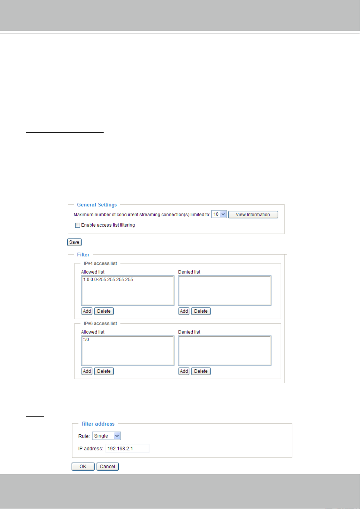
Access List
Advanced Mode
This section explains how to control access permission by verifying the client PC’s IP address�
General Settings
Maximum number of concurrent streaming connection(s) limited to: Simultaneous live viewing for 1~10
clients (including stream 1 and stream 2)� The default value is 10� If you modify the value and click Save,
all current connections will be disconnected and automatically attempt to re-link (IE Explore or Quick
Time Player)�
View Information: Click this button to display the connection status window showing a list of the current
connections� For example:
■ IP address: Current connections to the Network Camera.
■ Elapsed time: How much time the client has been at the webpage.
■ User ID: If the administrator has set a password for the webpage, the clients have to enter a user name
and password to access the live video� The user name will be displayed in the User ID column� If the
administrator allows clients to link to the webpage without a user name and password, the User ID
column will be empty�
There are some situations which allow clients access to the live video without a user name and
password:
1� The administrator does not set up a root password� For more information about how to set up a root
2. The administrator has set up a root password, but set RTSP Authentication to “disable“� For more
3. The administrator has set up a root password, but allows anonymous viewing. For more information
password and manage user accounts, please refer to Security on page 26�
information about RTSP Authentication, please refer to RTSP Streaming on page 41�
about Allow Anonymous Viewing, please refer to Security on page 26�
Page 46
VIVOTEK - A Leading Provider of Multimedia Communication Solutions
46 - User's Manual
■ Refresh: Click this button to refresh all current connections.
■ Add to deny list: You can select entries from the Connection Status list and add them to the Deny List
to deny access� Please note that those checked connections will only be disconnected temporarily
and will automatically try to re-link again (IE Explore or Quick Time Player)� If you want to enable the
denied list, please check Enable access list ltering and click Save in the rst column.
■ Disconnect: If you want to break off the current connections, please select them and click this
button� Please note that those checked connections will only be disconnected temporarily and will
automatically try to re-link again (IE Explore or Quick Time Player)�
Enable access list ltering: Check this item and click Save if you want to enable the access list ltering
function�
Filter
There are two lists for permission control: Allowed list and Denied list� Only those clients whose IP
addresses are on the Allowed list and not on the Denied list can access the Network Camera� Please
note that the IPv6 access list column will not be displayed unless you enable IPv6 on the Network page�
For more information about IPv6 Settings, please refer to page 36 for detailed information�
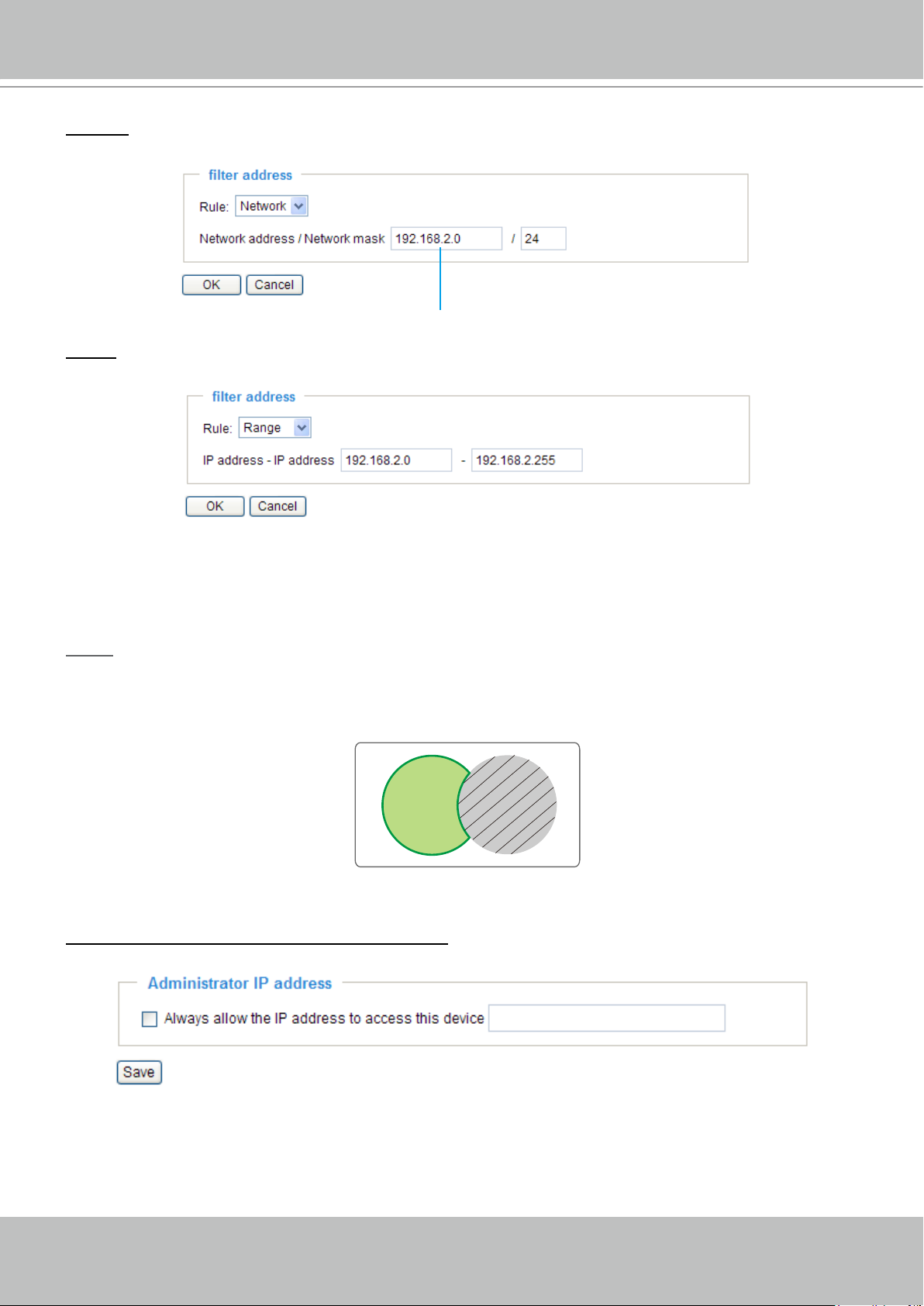
■ Add a rule to Allowed/Denied list: Click Add to add a rule to Allowed/Denied list.
There are three types of rules:
Single: This rule allows the user to add an IP address to the Allowed/Denied list.
For example:
Page 47
VIVOTEK - A Leading Provider of Multimedia Communication Solutions
User's Manual - 47
Allowed
List
Denied
List
Network: This rule allows the user to assign a network address and corresponding subnet mask to the
Allow/Deny List.
For example:
IP address 192�168�2�x will be blocked�
Range: This rule allows the user to assign a range of IP addresses to the Allow/Deny List. This rule is
only applied to IPv4�
For example:
■ Delete Allowed/Denied list:
In the Delete Allowed List or Delete Denied List column, make a selection and click Delete�
NOTE
► For example, when the range of IP addresses on the allowed list is set from 1.1.1.0 to
192.255.255.255 and the range in the denied list is set from 1.1.1.0 to 170.255.255.255, only users’
IPs between 171�0�0�0 and 192�255�255�255 can access the Network Camera�
Administrator IP address
Always allow the IP address to access this device: You can check this item and add the Administrator’s
IP address in this eld to make sure the Administrator can always connect to the device.
Page 48

VIVOTEK - A Leading Provider of Multimedia Communication Solutions
48 - User's Manual
Video Title
Title and Time
Video 17:08:56 2008/06/25
Audio and Video
This section explains how to cogure the audio and video settings of the Network Camera. It is
composed of the following two columns: Video Settings and Audio Settings�
Video Settings
Video title: Enter a name that will be displayed on the title bar of the live video�
Color: Select to display color or black/white video streams.
Power line frequency: Set the power line frequency consistent with local utility settings to eliminate image
flickering associated with fluorescent lights. Note that after the power line frequency is changed, you
must disconnect and reconnect the power cord of the Network Camera in order for the new setting to
take effect�
Video orientation: Flip--vertically reect the display of the live video; Mirror--horizontally reect the display
of the live video� Select both options if the Network Camera is installed upside-down (ex� on the ceiling)
to correct the image orientation�
Maximum exposure time: Select a proper maximum exposure time according to the light source of the
surroundings. The exposure times are selectable for the following durations: 1/120 second, 1/90 second,
1/30 second, 1/15 second, and 1/5 second. Shorter exposure times result in less light.
Overlay title and time stamp on video: Select this option to place the video title and time on the video
streams�
Page 49

VIVOTEK - A Leading Provider of Multimedia Communication Solutions
User's Manual - 49
17:08:56 2008/06/25
Note that when the frame size is set to 176 x 144 as shown in the picture below, only the time will be
stamped on the video streams�
Image Settings
Advanced Mode
Click Image settings to open the Image Settings page. On this page, you can tune the White balance,
Brightness, Saturation, Contrast, and Sharpness settings for the video.
White balance: Adjust the value for the best color temperature�
■ Auto
The Network Camera automatically adjusts the color temperature of the light in response to different light
sources� The white balance setting defaults to Auto and works well in most situations�
Page 50

VIVOTEK - A Leading Provider of Multimedia Communication Solutions
50 - User's Manual
■ Keep current value
Follow the steps below to manually set the white balance to compensate for the ambient lighting
conditions�
1� Set the White balance to Auto and click Save�
2. Place a sheet of white paper in front of the lens, then allow the Network Camera to adjust the color
temperature automatically�
3. Select Keep Current Value to conrm the setting while the white balance is being measured.
4� Click Save to enable the new setting�
Image Adjustment
■ Brightness: Adjust the image brightness level, which ranges from -5 to +5. The default value is set to 0.
■ Saturation: Adjust the image saturation level, which ranges from -5 to +5. The default value is set to 0.
■ Contrast: Adjust the image contrast level, which ranges from -5 to +5. The default value is set to 0.
■ Sharpness:
Adjust the image sharpness level, which ranges from -3 to +3. The default value is set to 0.
Enable Edge Enhancement
Edge enhancement is an image processing lter that enhances the edge contrast of an image or video to
improve its sharpness� Enter a value from 1 to 128 to set the degree of enhancement desired�
Enable Noise Reduction
Noise reduction is the process of removing noise from a signal� Select the type of noise to remove and
enter a value from 1 to 63 to set the degree of enhancement required�
You can click Preview to fine-tune the image, or click Restore to recall the original settings without
incorporating the changes. When completed with the settings on this page, click Save to enable the
setting and click Close to exit the page�
Page 51

VIVOTEK - A Leading Provider of Multimedia Communication Solutions
User's Manual - 51
Privacy Mask
Advanced Mode
Click Privacy Mask to open the settings page. On this page, you can block out sensitive zones to
address privacy concerns�
■ To set the privacy mask windows, follow the steps below:
1� Click New to add a new window�
2. Use the mouse to size and drag-drop the window, which is recommended to be at least twice the size
of the object (height and width) you want to cover�
3� Enter a Window Name and click Save to enable the setting�
4� Select Enable privacy mask to enable this function�
NOTE
Up to 5 privacy mask windows can be set up on the same screen�
►
► If you want to delete the
privacy mask
window, please click the ‘x’ on the upper right-hand corner of
the window�
Page 52

VIVOTEK - A Leading Provider of Multimedia Communication Solutions
52 - User's Manual
Video quality settings for stream 1 / stream 2
Advanced Mode
The Network Camera offers two choices of video compression standards for real-time viewing: MPEG-4
and MJPEG�
Click the items to display the detailed conguration settings. You can set up two seperate streams for the
Network Camera for different viewing devices. For example, set a smaller frame size and lower bit rate
for remote viewing on mobile phones and a larger video size and a higher bit rate for live viewing on web
browsers�
If MPEG-4 mode is selected, the video is streamed via RTSP protocol. There are four parameters
provided in MPEG-4 mode which allow you to adjust the video performance:
■ Frame size
Select the video size. Note that a larger frame size takes up more bandwidth. The frame sizes are
selectable in the following resolutions: 176 x 144, 320 x 240, and 640 x 480.
■ Maximum frame rate
This limits the maximum refresh frame rate per second� Set the frame rate higher for smoother video
quality�
If the power line frequency is set to 50Hz, the frame rates are selectable at 1fps, 2fps, 3fps, 5fps,
8fps, 10fps, 15fps, 20fps, and 25fps. If the power line frequency is set to 60Hz, the frame rates are
selectable at 1fps, 2fps, 3fps, 5fps, 8fps, 10fps, 15fps, 20fps, 25fps, and 30fps. You can also select
Customize and manually enter a value�
■ Intra frame period
Determine how often to plant an I frame. The shorter the duration, the more likely you will get better
video quality, but at the cost of higher network bandwidth consumption. Select the intra frame period
from the following durations: 1/4 second, 1/2 second, 1 second, 2 seconds, 3 seconds, and 4 seconds.
■ Video quality
A complex scene generally produces a larger le size, meaning that higher bandwidth will be needed
for data transmission. Therefore, if Constant bit rate is selected, the bandwidth utilization is xed at
a selected level, resulting in mutable video quality performance. The bit rates are selectable at the
following rates: 20Kbps, 30Kbps, 40Kbps, 50Kbps, 64Kbps, 128Kbps, 256Kbps, 512Kbps, 768Kbps,
1Mbps, 2Mbps, 3Mbps, and 4Mbps. You can also select Customize and manually enter a value�
On the other hand, if Fixed quality is selected, all frames are transmitted with the same quality;
bandwidth utilization is therefore unpredictable. The video quality can be adjusted to the following
settings: Medium, Standard, Good, Detailed, and Excellent. You can also select Customize and
manually enter a value�
Page 53

VIVOTEK - A Leading Provider of Multimedia Communication Solutions
User's Manual - 53
If JPEG mode is selected, the Network Camera continuously sends JPEG images to the client, producing
a moving effect similar to a filmstrip� Every single JPEG image transmitted guarantees the same
image quality, which in turn comes at the expense of variable bandwidth usage. Because the media
contents are a combination of JPEG images, no audio data is transmitted to the client. There are three
parameters provided in MJPEG mode to control the video performance:
■ Frame size
Select the video size. Note that a larger frame size takes up more bandwidth. The frame sizes are
selectable in the following resolutions: 176 x 144, 320 x 240, and 640 x 480.
■ Maximum frame rate
This limits the maximum refresh frame rate per second� Set the frame rate higher for smoother video
quality�
If the power line frequency is set to 50Hz, the frame rates are selectable at 1fps, 2fps, 3fps, 5fps,
8fps, 10fps, 15fps, 20fps, and 25fps. If the power line frequency is set to 60Hz, the frame rates are
selectable at 1fps, 2fps, 3fps, 5fps, 8fps, 10fps, 15fps, 20fps, 25fps, and 30fps. You can also select
Customize and manually enter a value�
■ Video quality
The video quality can be adjusted to the following settings: Medium, Standard, Good, Detailed, and
Excellent� You can also select Customize and manually enter a value�
NOTE
Video quality and fixed quality refers to the compression rate, so a lower value will produce higher
►
quality�
Page 54

VIVOTEK - A Leading Provider of Multimedia Communication Solutions
54 - User's Manual
Audio Settings
Mute: Select this option to disable audio transmission from the Network Camera to all clients� Note that
if mute mode is turned on, no audio data will be transmitted even if audio transmission is enabled on the
Client Settings page. In that case, the following message is displayed:
Internal microphone input gain: Select the gain of the internal audio input according to ambient
conditions� Adjust the gain from +21 db (most sensitive) ~ -33 db (least sensitive)�
External microphone input: Select the gain of the external audio input according to ambient conditions�
Adjust the gain from +21 db (most sensitive) or -33 db (least sensitive)�
Audio type: Select audio codec AAC or GSM-AMR and the bit rate
Advanced Mode
�
■ AAC provides good sound quality at the cost of higher bandwidth consumption. The bit rates are
selectable from: 16Kbps, 32Kbps, 48Kbps, 64Kbps, 96Kbps, and 128Kbps.
■ GSM-ARM is designed to optimize speech quality and requires less bandwidth. The bit rates are
selectable from: 4.75Kbps, 5.15Kbps, 5.90Kbps, 6.7Kbps, 7.4Kbps, 7.95Kbps,10.2Kbps, and
12�2Kbps�
When completed with the settings on this page, click Save to enable the settings�
NOTE
► The Network Camera offers two inputs to capture audio - internal microphone or external microphone.
The internal/external microphone switch is located on the back panel of the Network Camera.
Page 55

VIVOTEK - A Leading Provider of Multimedia Communication Solutions
User's Manual - 55
Video(TCP-AV)
Motion Detection
This section explains how to congure the Network Camera to enable motion detection. A total
of three motion detection windows can be congured.
Follow the steps below to enable motion detection:
1� Click New to add a new motion detection window�
2. In the Window Name text box, enter a name for the motion detection window.
■ To move and resize the window, drag and drop your mouse on the window.
■ To delete window, click X on the top right corner of the window.
3� Define the sensitivity to moving objects and the space ratio of all alerted pixels by moving the
Sensitivity and Percentage slider bar�
4� Click Save to enable the settings�
5� Select Enable motion detection to enable this function�
For example:
The Percentage Indicator will rise or fall depending on the variation between sequential images� When
motions are detected by the Network Camera and are judged to exceed the defined threshold, the
red bar rises. Meanwhile, the motion detection window will be outlined in red. Photos or videos can be
captured instantly and congured to be sent to a remote server (Email, FTP) by utilizing this feature as a
trigger source. For more information on how to set an event, please refer to Application on page 61�
Page 56

VIVOTEK - A Leading Provider of Multimedia Communication Solutions
56 - User's Manual
Percentage = 30%
A
B D
C
A green bar indicates that even though motions have been detected, the event has not been triggered
because the image variations still fall under the dened threshold.
This motion detection window will also be displayed on the Event Settings page� You can go to
Application > Event Settings > Trigger to choose it as a trigger source� Please refer to page 63 for
detailed information�
NOTE
► How does motion detection work?
There are two motion detection parameters: Sensitivity and Percentage. In the illustration above,
frame A and frame B are two sequential images� Pixel differences between the two frames are
detected and highlighted in gray (frame C) and will be compared with the sensitivity setting� Sensitivity
is a value that expresses the sensitivity to moving objects� Higher sensitivity settings are expected to
detect slight movements while smaller sensitivity settings will neglect them� When the sensitivity is set
to 70%, the Network Camera denes the pixels in the purple areas as “alerted pixels” (frame D).
Percentage is a value that expresses the proportion of “alerted pixels” to all pixels in the motion
detection window. In this case, 50% of pixels are identied as “alerted pixels”. When the percentage is
set to 30%, the motions are judged to exceed the dened threshold; therefore, the motion window will
be outlined in red�
For applications that require a high level of security management, it is suggested to use higher
sensitivity settings and smaller percentage values�
Page 57

VIVOTEK - A Leading Provider of Multimedia Communication Solutions
User's Manual - 57
Camera Tampering Detection
This section explains how to set up camera temper detection. With tamper detection, the
camera is capable of detecting incidents such as redirection, blocking or defocusing, or even
spray paint�
Please follow the steps below to set up the camera tamper detection function:
1� Check Enable camera tampering detection�
2� Enter the tamper trigger duration� (10 sec� ~ 10 min�) The tamper alarm will be triggered only when the
tampering factor (the difference between current frame and pre-saved background) exceeds the trigger
threshold�
3� Set up the event source as Camera Tamper Detection on Application page > Event Settings /Server
Settings (how to send alarm message) / Media Settings (send what type of alarm message)�
Please refer to page 63 for detailed information�
Page 58

VIVOTEK - A Leading Provider of Multimedia Communication Solutions
58 - User's Manual
Homepage Layout
Advanced Mode
This section explains how to set up your own customized homepage layout.
Preview
This column shows the settings of your homepage layout� You can manually select the background and
font colors in Theme Options (the third column on this page)� The settings will be displayed automatically
in this Preview eld. The following shows the homepage using the default settings:
Logo
Here you can change the logo at the top of your homepage�
Follow the steps below to upload a new logo:
1� Click Custom and the Browse eld will appear.
2. Select a logo image le from your local computer.
3� Click Upload to replace the existing logo with a new one�
4� Enter a website link if necessary�
5� Click Save to enable the settings�
Page 59

VIVOTEK - A Leading Provider of Multimedia Communication Solutions
User's Manual - 59
Font Color of the Video
Title
Font Color
Background Color of the
Control Area
Font Color of the Configuration Area
Background Color of the
Configuration Area
Background Color of the
Video Area
Frame Color
Theme Options
Here you can change the color of your homepage layout� There are three types of preset patterns for you
to choose from� The new layout will simultaneously appear in the Preview led. Click Save to enable the
settings�
Preset Patterns
Page 60
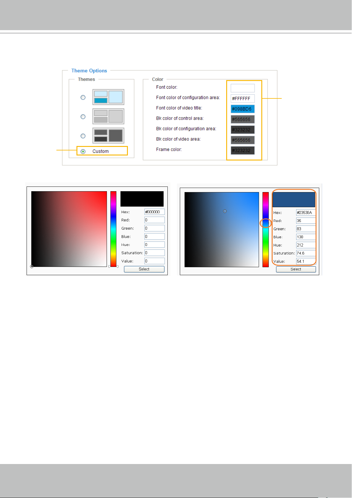
VIVOTEK - A Leading Provider of Multimedia Communication Solutions
60 - User's Manual
1
2
3
4
■ Follow the steps below to set up a customized homepage:
1� Click Custom on the left column�
2. Click the eld where you want to change the color on the right column.
Custom
Pattern
3� The palette window will pop up as shown below�
Color Selector
4� Drag the slider bar and click on the left square to select a desired color�
5. The selected color will be displayed in the corresponding elds and in the Preview column�
6� Click Save to enable the settings�
Page 61

VIVOTEK - A Leading Provider of Multimedia Communication Solutions
User's Manual - 61
ex. Motion Detection,
Digital Input,
System Reboot
Event Trigger
ex. Snapshot, Video Clips,
System Log, Digital Output
ex. Email, FTP, HTTP Server,
Network Storage
Media
(what to send)
Server
(where to send)
Action
Application
Advanced Mode
This section explains how to congure the Network Camera to responds to particular situations
(event). A typical application is that when a motion is detected, the Network Camera sends
buffered images to an FTP server or e-mail address as notications.
In the illustation on the right, an event can be triggered
by many sources, such as motion detection or external
digital input devices. When an event is triggered, you
can specify what type of action that will be performed�
You can configure the Network Camera to send
snapshots or videos to your email address or FTP site�
Customized Script
This function allows you to upload a sample script (.xml le) to the webpage, which will save your time on
conguring the settings. Please note that there is a limited number of customized scripts you can upload;
if the current amount of customized scripts has reached the limit, an alert message will pop up. If you
need more information, please ask for VIVOTEK technical support.
Click to upload a le
Click to modify the
script online
Page 62

VIVOTEK - A Leading Provider of Multimedia Communication Solutions
62 - User's Manual
Event Settings
In the Event Settings column, click Add to open the Event Settings page. On this page, you can
arrange three elements -- Trigger, Schedule, and Action to set an event. A total of 3 event settings can be
congured.
Event name: Enter a name for the event setting�
Enable this event: Select this option to enable the event setting�
Priority: Select the relative importance of this event (High, Normal, or Low). Events with a higher priority
setting will be executed rst.
Detect next event after
seconds: Enter the duration in seconds to pause motion detection after a
motion is detected�
Page 63
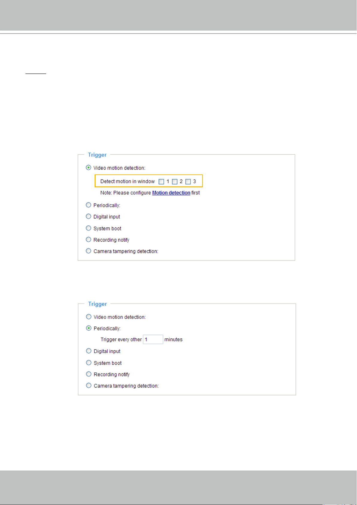
VIVOTEK - A Leading Provider of Multimedia Communication Solutions
User's Manual - 63
An event is an action initiated by a user-defined trigger source; it is the causal arrangement of the
following three elements: Trigger, Event Schedule, and Action.
Trigger
This is the cause or stimulus which denes when to trigger the Network Camera. The trigger source can
be congured to use the Network Camera’s built-in motion detection mechanism or external digital input
devices�
There are several choices of trigger sources as shown below�
Select the item to display the detailed
conguration options.
■ Video motion detection
This option makes use of the built-in motion detection mechanism as a trigger source� To enable this
function, you need to congure a Motion Detection Window rst. For more information, please refer to
Motion Detection on page 55 for details�
■ Periodically
This option allows the Network Camera to trigger periodically for every other dened minute. Up to 999
minutes are allowed�
■ Digital input
This option allows the Network Camera to use an external digital input device or sensor as a trigger
source. Depending on your application, there are many choices of digital input devices on the market
which helps to detect changes in temperature, vibration, sound, and light, etc.
■ System boot
This option triggers the Network Camera when the power to the Network Camera is disconnected�
Page 64

VIVOTEK - A Leading Provider of Multimedia Communication Solutions
64 - User's Manual
■ Recording notify
This option allows the Network Camera to trigger when the recording disk is full or when recording
starts to rewrite older data� If you want receive Recording notify message, please refer to page 72
for detailed information�
■ Camera tampering detection
This option allows the Network Camera to trigger when the camera detects that is is being tampered
with� To enable this function, you need to congure the Tampering Detection option rst. Please refer
to page 57 for detailed information�
Event Schedule
Specify the period for the event�
■ Select the days of the week.
■ Select the recording schedule in 24-hr time format.
Action
Dene the actions to be performed by the Network Camera when a trigger is activated.
■ Trigger digital output for
seconds
Select this option to turn on the external digital output device when a trigger is activated� Specify the
length of the trigger interval in the text box�
Page 65

VIVOTEK - A Leading Provider of Multimedia Communication Solutions
User's Manual - 65
To set an event with recorded video or snapshots, it is necessary to congure the server and
media settings so that the Network Camera will know what action to take (such as which server
to send the media files to) when a trigger is activated�
■ Add
Server / Add Media
Click Add Server to configure Server Settings. For more information, please refer to Server Settings
on page 67�
Click Add Media to configure Media Settings� For more information, please refer to Media Settings on
page 70�
Here is an example of the Event Settings page:
Page 66

VIVOTEK - A Leading Provider of Multimedia Communication Solutions
66 - User's Manual
When completed, click Save to enable the settings and click Close to exit the Event Settings page�
The new event settings / server settings / media settings will appear in the event drop-down list on the
Application page�
Here is an example of the Application page with an event setting:
When the Event Status is ON, once an event is triggered by motion detection, the Network Camera will
automatically send snapshots via e-mail�
If you want to stop the event trigger, you can click ON to turn it to OFF status or click Delete to remove
the event setting�
To remove a server setting from the list, select a server name from the drop-down list and click Delete�
Note that only when the server setting is not being applied to an event setting can it be deleted�
To remove a media setting from the list, select a media name from the drop-down list and click Delete�
Note that only when the media setting is not being applied to an event setting can it be deleted�
Page 67

VIVOTEK - A Leading Provider of Multimedia Communication Solutions
User's Manual - 67
Server Settings
Click Add Server on the Event Settings page to open the Server Setting page. On this page, you can
specify where the notication messages are sent when a trigger is activated. A total of 5 server settings
can be congured.
Server name: Enter a name for the server setting�
Server Type
There are four choices of server types available: Email, FTP, HTTP, and Network storage.
to display the detailed conguration options. You can congure either one or all of them.
Email: Select to send the media les via email when a trigger is activated.
Select the item
■ Sender email address: Enter the email address of the sender.
■ Recipient email address: Enter the email address of the recipient.
■ Server address: Enter the domain name or IP address of the email server.
■ User name: Enter the user name of the email account if necessary.
■ Password: Enter the password of the email account if necessary.
■ Server port: The defualt mail server port is set to 25. You can also manually set another port.
If your SMTP server requires a secure connection (SSL), check This server requires a secure
connection (SSL).
To verify if the email settings are correctly congured, click Test. The result will be shown in a pop-up
window. If successful, you will also receive an email indicating the result.
Click Save to enable the settings, then click Close to exit the page�
Page 68

VIVOTEK - A Leading Provider of Multimedia Communication Solutions
68 - User's Manual
FTP: Select to send the media les to an FTP server when a trigger is activated.
■ Server address: Enter the domain name or IP address of the FTP server.
■ Server port
By default, the FTP server port is set to 21. It can also be assigned to another port number between
1025 and 65535�
■ User name: Enter the login name of the FTP account.
■ Password: Enter the password of the FTP account.
■ Remote folder name
Enter the folder where the media file will be placed. If the folder name entered does not exist, the
Network Camera will create it on the FTP server�
■ Passive mode
Most firewalls do not accept new connections initiated from external requests� If the FTP server
supports passive mode, select this option to enable passive mode FTP and allow data transmission to
pass through the rewall.
To verify if the FTP settings are correctly congured, click Test� The result will be shown in a pop-up
window as shown below. If successful, you will also receive a test.txt le on the FTP server.
Click Save to enable the settings, then click Close to exit the page�
Page 69

VIVOTEK - A Leading Provider of Multimedia Communication Solutions
User's Manual - 69
HTTP: Select to send the media les to an HTTP server when a trigger is activated.
■ URL: Enter the URL of the HTTP server.
■ User name: Enter the user name if necessary.
■ Password: Enter the password if necessary.
To verify if the HTTP settings are correctly congured, click Test� The result will be shown in a pop-up
window as below. If successful, you will receive a test.txt le on the HTTP server.
Click Save to enable the settings, then click Close to exit the page�
Network storage: Select to send the media les to a network storage location when a trigger is activated�
Please refer to Network Storage Setting on page 74 for details�
Click Save to enable the settings, then click Close to exit the page�
When completed, the new server settings will automatically be displayed on the Event Settings page.
For example:
Page 70

VIVOTEK - A Leading Provider of Multimedia Communication Solutions
70 - User's Manual
1 pic. 2 pic. 3 pic. 4 pic. 5 pic. 6 pic. 7 pic. 8 pic. 9 pic.
10 pic. 11 pic. 10 pic. 12 pic. 13 pic. 14 pic. 15 pic.
Trigger Activation
Snapshot_20080104_100341
Date and time suffix
The format is: YYYYMMDD_HHMMSS
File name prefix
Media Settings
Click Add Media on the Event Settings page to open the Media Settings page. On this page, you can
specify the type of media that will be sent when a trigger is activated� A total of 5 media settings can be
congured.
Media name: Enter a name for the media setting�
Media Type
There are three media types available: Snapshot, Video Clip, and System log.
the detailed conguration options. You can congure either or all of them.
Snapshot: Select to send snapshots when a trigger is activated�
Select the item to display
■ Source: Select to take snapshots from stream 1 or stream 2.
■ Send
pre-event images
The Network Camera has a buffer area; it temporarily holds data up to a certain limit� Enter a number
to decide how many images to capture before a trigger is activated� Up to 7 images can be generated�
■ Send
post-event images
Enter a number to decide how many images to capture after a trigger is activated� Up to 7 images can
be generated�
For example, if both the Send pre-event images and Send post-event images are set to 7, a total of 15
images are generated after a trigger is activated�
■ File name prex
Enter the text that will be appended to the front of the le name.
■ Add date and time sufx to the le name
Select this option to append the date/time to the le name.
For example:
Click Save to enable the settings, then click Close to exit the page�
Page 71

VIVOTEK - A Leading Provider of Multimedia Communication Solutions
User's Manual - 71
Video_20080104_100341
Date and time suffix
The format is: YYYYMMDD_HHMMSS
File name prefix
1 sec. 2 sec. 3 sec. 4 sec. 5 sec. 6 sec. 7 sec. 8 sec. 9 sec. 10 sec.
Trigger Activation
Video clip: Select to send video clips when a trigger is activated�
■ Source: Select to record video clips from stream 1 or stream 2.
■ Pre-event recording
The Network Camera has a buffer area; it temporarily holds data up to a certain limit� Enter a number
to decide the duration of recording before a trigger is activated� Up to 9 seconds can be set�
■ Maximum duration
Specify the maximum recording duration in seconds� Up to 10 seconds can be set�
For example, if pre-event recording is set to five seconds and the maximum duration is set to ten
seconds, the Network Camera continues to record for another 4 seconds after a trigger is activated.
■ Maximum le size
Specify the maximum le size allowed.
■ File name prex
Enter the text that will be appended to the front of the le name.
For example:
Click Save to enable the settings, then click Close to exit the page�
System log: Select to send a system log when a trigger is activated�
Click Save to enable the settings, then click Close to exit the page�
Page 72

VIVOTEK - A Leading Provider of Multimedia Communication Solutions
72 - User's Manual
Recording notify message: Select to send a recording notication message when a trigger is activated.
The following is an example of a recording notication message (.txt le), which shows a list of deleted
previously-recorded data due to cycle recording�
When completed, click Save to enable the settings and click Close to exit this page� The new media
settings will appear on the Event Settings page�
You can continue to select a server and media type for the event� Please go back to page 66 for detailed
information�
■ Create folders by date, time, and hour automatically: If you check this item, the system will generate
folders automatically by date�
■ View: Click this button to open a le list window. This function is only for Network Storage�
If you click View button of Network storage, a file directory window will pop up for you to view
recorded data on Network storage. For detailed illustration, please refer to next page�
Page 73

VIVOTEK - A Leading Provider of Multimedia Communication Solutions
User's Manual - 73
20081120
20081121
20081122
The following is an example of a le destination with video clips:
The format is: YYYYMMDD
Click to open the directory
Click to delete selected items
Click 20081120 to open the directory:
The format is: HH (24r)
Click to open the le list for that hour
Click to delete
selected items
Click to delete all
recorded data
Click to delete all recorded data
Click to go back to the previous
level of the directory
The format is: File name prex + Minute (mm)
You can set up the le name prex on Media Settings page.
Please refer to page 70 for detailed information�
Page 74

VIVOTEK - A Leading Provider of Multimedia Communication Solutions
74 - User's Manual
1
2
3
4
Network storage path
(\\server name or IP address\folder name)
User name and password for your server
Recording
Advanced Mode
This section explains how to congure the recording settings for the Network Camera.
Recording Settings
NOTE
► Before setting up this page, please set up the Network Storage on the Server Settings page rst.
Network Storage Setting
Click Server to open the Server Settings page and follow the steps below:
1� Fill in the information for your server�
For example:
2� Click Test to check the setting� The result will be shown in the pop-up window�
Page 75

VIVOTEK - A Leading Provider of Multimedia Communication Solutions
User's Manual - 75
If successful, you will receive a test.txt le on the network storage server.
3� Enter a server name�
4� Click Save to enable the settings and click Close to exit the page�
Recording Settings
Click Add to open the recording setting page. On this page, you can define the recording source,
recording schedule and recording capacity. A total of 2 recording settings can be congured.
Recording name: Enter a name for the recording setting�
Enable this recording: Select this option to enable video recording�
Priority: Select the relative importance of the recording setting (High, Normal, and Low).
Page 76

VIVOTEK - A Leading Provider of Multimedia Communication Solutions
76 - User's Manual
20081120
20081121
20081122
Source: Select the recording source (stream 1 or stream 2)�
Recording Schedule: Specify the recording duration�
■ Select the days of the week.
■ Select the recording start and end times in a 24-hr time format.
Destination: You can select the SD card or network storage to strore the recorded video les.
Capacity: You can choose either the entire free space available or limit the recording size. The recording
size limit must be larger than the reserved amount for cyclic recording.
File name prex: Enter the text that will be appended to the front of the le name.
Enable cyclic recording: If you check this item, when the maximum capacity is reached, the oldest le
will be overwritten by the latest one� The reserved amount is reserved for cyclic recording to prevent
malfunction� This value must be larger than 15 MBytes�
If you want to enable recording notication, please click Application to set up� Please refer to Trigger >
Recording notify on page 64 for detailed information�
When completed, select Enable this recording� Click Save to enable the setting and click Close to exit
this page. When the system begins recording, it will send the recorded les to the Network Storage.
The new recording name will appear in the drop-down list on the recording page as shown below�
To remove a recording setting from the list, select a recording name from the drop-down list and click
Delete�
■ Click Video (Name): Opens the Recording Settings page to modify�
■ Click ON (Status): The Status will become OFF and stop recording�
■ Click NAS (Destination): Opens the le list of recordings as shown below. For more information about
folder naming rules, please refer to page 73 for details�
Page 77

VIVOTEK - A Leading Provider of Multimedia Communication Solutions
User's Manual - 77
System Log
Advanced Mode
This section explains how to configure the Network Camera to send the system log to the
remote server as backup�
Remote Log
You can congure the Network Camera to send the system log le to a remote server as a log backup.
Before utilizing this feature, it is suggested that the user install a log-recording tool to receive system log
messages from the Network Camera� An example is Kiwi Syslog Daemon� Visit http://www.kiwisyslog.
com/kiwi-syslog-daemon-overview/�
Follow the steps below to set up the remote log:
1. In the IP address text box, enter the IP address of the remote server.
2. In the port text box, enter the port number of the remote server.
3. When completed, select Enable remote log and click Save to enable the setting�
Current Log
This column displays the system log in chronological order� The system log is stored in the Network
Camera’s buffer area and will be overwritten when reaching the maximum limit�
Page 78

VIVOTEK - A Leading Provider of Multimedia Communication Solutions
78 - User's Manual
View Parameters
Advanced Mode
The View Parameters page lists the entire system’s parameters in alphabetical order� If you
need technical assistance, please provide the information listed on this page.
Page 79

VIVOTEK - A Leading Provider of Multimedia Communication Solutions
User's Manual - 79
Maintenance
This chapter explains how to restore the Network Camera to factory default, upgrade rmware
version, etc.
Reboot
This feature allows you to reboot the Network Camera, which takes about one minute to complete. When
completed, the live video page will be displayed in your browser. The following message will be displayed
during the reboot process�
If the connection fails after rebooting, manually enter the IP address of the Network Camera in the
address eld to resume the connection.
Restore
This feature allows you to restore the Network Camera to factory default settings�
Network Type: Select this option to retain the Network Type settings (please refer to Network Type on
page 32)�
Daylight Saving Time: Select this option to retain the Daylight Saving Time settings (please refer to
System on page 24)�
Custom Language: Select this option to retain the Custom Language settings�
If none of the options are selected, all settings will be restored to factory default.
The following message is displayed during the restoring process�
Page 80

VIVOTEK - A Leading Provider of Multimedia Communication Solutions
80 - User's Manual
Export / Upload Files
Advanced Mode
This feature allows you to Export / Upload daylight saving time rules, custom language les, and setting
backup les.
Export daylight saving time conguration le: Click to set the start and end time of DST�
Follow the steps below to export:
1. In the Export les column, click Export to export the daylight saving time conguration le from the
Network Camera�
2. A le download dialog will pop up as shown below. Click Open to review the XML le or click Save to
store the le for editing.
®
3. Open the le with Microsoft
Notepad and locate your time zone; set the start and end time of DST.
When completed, save the le.
In the example below, DST begins each year at 2:00 a.m. on the second Sunday in March and ends at
2:00 a.m. on the rst Sunday in November.
Page 81

VIVOTEK - A Leading Provider of Multimedia Communication Solutions
User's Manual - 81
Upload daylight saving time rule: Click Browse… and specify the XML le to upload.
If the incorrect date and time are assigned, you will see the following warning message when uploading
the le to the Network Camera.
The following message is displayed when attempting to upload an incorrect le format.
Export language file: Click to export language strings� VIVOTEK provides nine languages: English,
Deutsch, Español, Français, Italiano,
日本語
, Português,
簡体中文
, and
繁體中文
�
Upload custom language le: Click Browse… and specify your own custom language le to upload.
Export setting backup le: Click to export all parameters for the device and user-dened scripts.
Upload setting backup le: Click Browse… to upload a setting backup le. Please note that the model
and rmware version of the device should be the same as the setting backup le. If you have set up a
xed IP or other special settings for your device, it is not suggested to upload a settings backup le.
Upgrade Firmware
This feature allows you to upgrade the firmware of your Network Camera� It takes a few minutes to
complete the process�
Note: Do not power off the Network Camera during the upgrade!
Follow the steps below to upgrade the rmware:
1. Download the latest rmware le from the VIVOTEK website. The le is in .pkg le format.
2� Click Browse… and specify the rmware le.
3� Click Upgrade� The Network Camera starts to upgrade and will reboot automatically when the upgrade
completes�
If the upgrade is successful, you will see “Reboot system now!! This connection will close”. After that, re-
access the Network Camera�
Page 82

VIVOTEK - A Leading Provider of Multimedia Communication Solutions
82 - User's Manual
Starting firmware upgrade...
Do not power down the server during the upgrade.
The server will restart automatically after the upgrade is
completed.
This will take about 1 - 5 minutes.
Wrong PKG file format
Unpack fail
0
IP7130 - VVTK - 0100b
The following message is displayed when the upgrade has succeeded�
The following message is displayed when you have selected an incorrect rmware le.
Page 83

VIVOTEK - A Leading Provider of Multimedia Communication Solutions
User's Manual - 83
Appendix
URL Commands for the Network Camera
Overview
For some customers who already have their own web site or web control application, the Network
Camera/Video Server can be easily integrated through URL syntax. This section specifies the external
HTTP-based application programming interface� The HTTP-based camera interface provides the
functionality to request a single image, control camera functions (PTZ, output relay etc.), and get and set
internal parameter values� The image and CGI-requests are handled by the built-in Web server�
Style Convention
In URL syntax and in descriptions of CGI parameters, text within angle brackets denotes content that
is to be replaced with either a value or a string. When replacing the text string, the angle brackets
should also be replaced. An example of this is the description of the name for the server, denoted with
<servername> in the URL syntax description below, that is replaced with the string myserver in the URL
syntax example further down in the page�
URL syntax is denoted with the word "Syntax:" written in bold face followed by a box with the referenced
syntax as shown below. For example, name of the server is written as <servername> and is intended to
be replaced with the name of the actual server. This can either be a name, e.g., "mywebcam" or "thecam.
adomain.net" or the associated IP number for the server, e.g., 192.168.0.220.
Syntax:
http://<servername>/cgi-bin/viewer/video.jpg
Description of returned data is written with "Return:" in bold face followed by the returned data in a box. All data is
returned in HTTP format, i.e., each line is separated with a Carriage Return and Line Feed (CRLF) printed as \r\n.
Return:
HTTP/1.0 <HTTP code> <HTTP text>\r\n
URL syntax examples are written with "Example:" in bold face followed by a short description and a light grey box
with the example�
Example: request a single snapshot image
http://mywebserver/cgi-bin/viewer/video.jpg
Page 84

VIVOTEK - A Leading Provider of Multimedia Communication Solutions
84 - User's Manual
Overview
For some customers who already have their own web site or web control application, a Network
Camera/Video server can be easily integrated through URLs. This document provides the supersets of URL
commands V2 for VIVOTEK 7000 series products.
This section specifies the external HTTP-based application programming interface. The HTTP-based camera
interface provides the functionality to request a single image, to control camera functions (PTZ, output relay
etc.), and to get and set internal parameter values. The image and CGI-requests are handled by the built-in
Web server.
Style Convention
In URL syntax and in descriptions of CGI parameters, a text within angle brackets denotes a content that is
to be replaced with either a value or a string. When replacing the text string, the angle brackets shall also be
replaced. An example of this is the description of the name for the server, denoted with <servername> in the
URL syntax description below, which is replaced with the string myserver in the URL syntax example, also
below.
URL syntax is written with the word “Syntax:" written in bold face followed by a box with the reference
syntax as seen below. The name of the server is written as <servername>. This is intended to be replaced
with the name of the actual server. This can either be a name, e.g., "mywebcam" or "thecam.adomain.net"
or the associated IP number for the server, e.g., 192.168.0.220.
Special notes will be marked in RED.
Syntax:
http://<servername>/cgi-bin/viewer/video.jpg
Description of returned data is written with "Return:" in bold face followed by the returned data shown in a
box. All data is returned as HTTP formatted, i.e., starting with the string HTTP and line separated with a
Carriage Return and Line Feed (CRLF) printed as \r\n.
Return:
HTTP/1.0 <HTTP code> <HTTP text>\r\n
URL syntax examples are written with "Example:" in bold face followed by a short description and a light
grey box with the example.
Example: Request a single snapshot image
http://mywebserver/cgi-bin/viewer/video.jpg
Page 85

VIVOTEK - A Leading Provider of Multimedia Communication Solutions
User's Manual - 85
General CGI URL Syntax and Parameters
CGI parameters are written in lower-case and as one word without any underscores or other separators.
When the CGI request includes internal camera parameters, these parameters must be written exactly as
they are named in the camera or video server. The CGIs are organized in functionally-related directories
under the cgi-bin directory. The file extension .cgi is required.
Syntax:
http://<servername>/cgi-bin/<subdir>[/<subdir>...]/<cgi>.<ext>
[?<parameter>=<value>[&<parameter>=<value>...]]
Example: Set digital output #1 to active
http://mywebserver/cgi-bin/dido/setdo.cgi?do1=1
Security Level
SECURITY LEVEL SUB-DIRECTORY DESCRIPTION
0 anonymous Unprotected.
1 [view] anonymous, viewer,
dido, camctrl
1. Can view, listen, talk to camera.
2. Can control DI/DO, PTZ of the camera.
4 [operator] anonymous, viewer,
dido, camctrl, operator
Operator access rights can modify most of the camera’s
parameters except some privileges and network options.
6 [admin] anonymous, viewer,
dido, camctrl, operator,
admin
Administrator access rights can fully control the camera’s
operations.
7 N/A Internal parameters. Unable to be changed by any external
interfaces.
Get Server Parameter Values
Note: The access right depends on the URL directory.
Method: GET/POST
Syntax:
http://<servername>/cgi-bin/anonymous/getparam.cgi?[<parameter>]
[&<parameter>…]
http://<servername>/cgi-bin/viewer/getparam.cgi?[<parameter>]
[&<parameter>…]
Page 86

VIVOTEK - A Leading Provider of Multimedia Communication Solutions
86 - User's Manual
http://<servername>/cgi-bin/operator/getparam.cgi?[<parameter>]
[&<parameter>…]
http://<servername>/cgi-bin/admin/getparam.cgi?[<parameter>]
[&<parameter>…]
Where the <parameter> should be <group>[_<name>] or <group>[.<name>]. If you do not specify any
parameters, all the parameters on the server will be returned. If you specify only <group>, the parameters
of the related group will be returned.
When querying parameter values, the current parameter values are returned.
A successful control request returns parameter pairs as follows:
Return:
HTTP/1.0 200 OK\r\n
Content-Type: text/html\r\n
Context-Length: <length>\r\n
\r\n
<parameter pair>
where <parameter pair> is
<parameter>=<value>\r\n
[<parameter pair>]
<length> is the actual length of content.
Example: Request IP address and its response
Request:
http://192.168.0.123/cgi-bin/admin/getparam.cgi?network_ipaddress
Response:
HTTP/1.0 200 OK\r\n
Content-Type: text/html\r\n
Context-Length: 33\r\n
\r\n
network.ipaddress=192.168.0.123\r\n
Set Server Parameter Values
Note: The access right depends on the URL directory.
Page 87

VIVOTEK - A Leading Provider of Multimedia Communication Solutions
User's Manual - 87
Method: GET/POST
Syntax:
http://<servername>/cgi-bin/anonymous/setparam.cgi? <parameter>=<value>
[&<parameter>=<value>…][&update=<value>][&return=<return page>]
http://<servername>/cgi-bin/viewer/setparam.cgi? <parameter>=<value>
[&<parameter>=<value>…][&update=<value>] [&return=<return page>]
http://<servername>/cgi-bin/operator/setparam.cgi? <parameter>=<value>
[&<parameter>=<value>…][&update=<value>] [&return=<return page>]
http://<servername>/cgi-bin/admin/setparam.cgi? <parameter>=<value>
[&<parameter>=<value>…][&update=<value>] [&return=<return page>]
PARAMETER VALUE DESCRIPTION
<group>_<name>
value to assigned Assign <value> to the parameter <group>_<name>.
update
<boolean> Set to 1 to update all fields (no need to update parameter in
each group).
return
<return page> Redirect to the page <return page> after the parameter is
assigned. The <return page> can be a full URL path or relative
path according to the current path. If you omit this parameter, it
will redirect to an empty page.
(Note : The retu rn page c an be a gen era l HTML file (.htm, .html)
or a VIVOTEK server script executable (.vspx) file. It cannot be
a CGI command or have any extra parameters. This parameter
must be placed at the end of the parameter list
Return:
HTTP/1.0 200 OK\r\n
Content-Type: text/html\r\n
Context-Length: <length>\r\n
\r\n
<parameter pair>
where <parameter pair> is
<parameter>=<value>\r\n
[<parameter pair>]
Only the parameters that you set and are readable will be returned.
Page 88

VIVOTEK - A Leading Provider of Multimedia Communication Solutions
88 - User's Manual
Example: Set the IP address of server to 192.168.0.123:
Request:
http://myserver/cgi-bin/admin/setparam.cgi?network_ipaddress=192.168.0.123
Response:
HTTP/1.0 200 OK\r\n
Content-Type: text/html\r\n
Context-Length: 33\r\n
\r\n
network.ipaddress=192.168.0.123\r\n
Available parameters on the server
Valid values:
VALID VALUES DESCRIPTION
string[<n>] Text strings shorter than ‘n’ characters. The characters “,’, <,>,& are invalid.
password[<n>] The same as string but displays ‘*’ instead.
integer Any number between (-231 – 1) and (231 – 1).
positive integer Any number between 0 and (232 – 1).
<m> ~ <n> Any number between ‘m’ and ‘n’.
domain name[<n>] A string limited to a domain name shorter than ‘n’ characters (eg.
www.ibm.com).
email address [<n>] A string limited to an email address shorter than ‘n’ characters (eg.
joe@www.ibm.com).
ip address A string limited to an IP address (eg. 192.168.1.1).
mac address A string limited to contain a MAC address without hyphens or colons.
boolean A boolean value of 1 or 0 represents [Yes or No], [True or False], [Enable or
Disable].
<value1>,
<value2>,
<value3>,
…
Enumeration. Only given values are valid.
blank A blank string.
everything inside <> A description
positive Integer Any number between 0 and (232 – 1)
integer primary key SQLite data type. A 32-bit signed integer. The value is assigned a unique
integer by the server.
text SQLite data type. The value is a text string, stored using the database
encoding (UTF-8, UTF-16BE or UTF-16-LE).
Page 89

VIVOTEK - A Leading Provider of Multimedia Communication Solutions
User's Manual - 89
NOTE: The camera should not be restarted when parameters are changed.
Group: system
NAME VALUE SECURITY
(get/set)
DESCRIPTION
hostname string[40] 1/6 Host name of server
(Network Camera,
Wireless Network Camera,
Video Server,
Wireless Video Server).
ledoff <boolean> 6/6 Turn on (0) or turn off (1) all led
indicators.
date <yyyy/mm/dd>,
keep,
auto
6/6 Current date of system. Set to ‘keep’
to keep date unchanged. Set to ‘auto’
to use NTP to synchronize date.
time <hh:mm:ss>,
keep,
auto
6/6 Current time of the system. Set to
‘keep’ to keep time unchanged. Set to
‘auto’ to use NTP to synchronize time.
datetime <MMDDhhmmYYYY.ss> 6/6 Another current time format of the
system.
ntp <domain name>,
<ip address>,
<blank>
6/6 NTP server.
*Do not use “skip to invoke default
server” for default value.
timezoneindex -489 ~ 529 6/6 Indicate timezone and area.
-480: GMT-12:00 Eniwetok,
Kwajalein
-440: GMT-11:00 Midway Island,
Samoa
-400: GMT-10:00 Hawaii
-360: GMT-09:00 Alaska
-320: GMT-08:00 Las Vegas,
San_Francisco, Vancouver
-280: GMT-07:00 Mountain Time,
Denver
-281: GMT-07:00 Arizona
-240: GMT-06:00 Central America,
Central Time, Mexico City,
Saskatchewan
-200: GMT-05:00 Eastern Time, New
York, Toronto
Page 90

VIVOTEK - A Leading Provider of Multimedia Communication Solutions
90 - User's Manual
-201: GMT-05:00 Bogota, Lima,
Quito, Indiana
-160: GMT-04:00 Atlantic Time,
Canada, Caracas, La Paz, Santiago
-140: GMT-03:30 Newfoundland
-120: GMT-03:00 Brasilia, Buenos
Aires, Georgetown, Greenland
-80: GMT-02:00 Mid-Atlantic
-40: GMT-01:00 Azores,
Cape_Verde_IS.
0: GMT Casablanca, Greenwich Mean
Time: Dublin, Edinburgh, Lisbon,
London
40: GMT 01:00 Amsterdam, Berlin,
Rome, Stockholm, Vienna, Madrid,
Paris
41: GMT 01:00 Warsaw, Budapest,
Bern
80: GMT 02:00 Athens, Helsinki,
Istanbul, Riga
81: GMT 02:00 Cairo
82: GMT 02:00 Lebanon, Minsk
83: GMT 02:00 Israel
120: GMT 03:00 Baghdad, Kuwait,
Riyadh, Moscow, St. Petersburg,
Nairobi
121: GMT 03:00 Iraq
140: GMT 03:30 Tehran
160: GMT 04:00 Abu Dhabi, Muscat,
Baku, Tbilisi, Yerevan
180: GMT 04:30 Kabul
200: GMT 05:00 Ekaterinburg,
Islamabad, Karachi, Tashkent
220: GMT 05:30 Calcutta, Chennai,
Mumbai, New Delhi
230: GMT 05:45 Kathmandu
240: GMT 06:00 Almaty, Novosibirsk,
Astana, Dhaka, Sri Jayawardenepura
260: GMT 06:30 Rangoon
280: GMT 07:00 Bangkok, Hanoi,
Page 91

VIVOTEK - A Leading Provider of Multimedia Communication Solutions
User's Manual - 91
Jakarta, Krasnoyarsk
320: GMT 08:00 Beijing, Chongging,
Hong Kong, Kuala Lumpur, Singapore,
Taipei
360: GMT 09:00 Osaka, Sapporo,
Tokyo, Seoul, Yakutsk
380: GMT 09:30 Adelaide, Darwin
400: GMT 10:00 Brisbane, Canberra,
Melbourne, Sydney, Guam,
Vladivostok
440: GMT 11:00 Magadan, Solomon
Is., New Caledonia
480: GMT 12:00 Aucklan, Wellington,
Fiji, Kamchatka, Marshall Is.
520: GMT 13:00 Nuku'Alofa
formertimezoneindex -489 ~ 529 6/6 Record the last time zone for time
jump when changing time zones.
daylight_enable <boolean> 6/6 Enable automatic daylight saving
time in time zone.
daylight_dstactualmode <boolean> 6/7 Check if current time is under daylight
saving time.
daylight_auto_begintime string[19] 6/7 Display the current daylight saving
start time.
(product dependent)
daylight_auto_endtime string[19] 6/7 Display the current daylight saving
end time.
(product dependent)
daylight_manual_offset <integer> 6/6 Manually set daylight saving time with
offset.
daylight_manual_begintime string[19] 6/6 Manually set daylight saving time
beginning.
daylight_manual_endtime string[19] 6/6 Manually set daylight saving time
end.
updateinterval 0,
3600,
86400,
604800,
2592000
6/6 0 to Disable automatic time
adjustment, otherwise, it indicates
the seconds between NTP automatic
update intervals.
enableir <boolean> 6/6 Enable IR control
(capability.nir>0)
Page 92

VIVOTEK - A Leading Provider of Multimedia Communication Solutions
92 - User's Manual
(product dependent).
restore 0,
<positive integer>
7/6 Restore the system parameters to
default values after <value> seconds.
reset 0,
<positive integer>
7/6 Restart the server after <value>
seconds if <value> is non-negative.
restoreexceptnet <Any value> 7/6 Restore the system parameters to
default values except (ipaddress,
subnet, router, dns1, dns2, pppoe).
This command can cooperate with
other “restoreexceptXYZ” commands.
When cooperating with others, the
system parameters will be restored to
the default value except for a union of
the combined results.
restoreexceptdst <Any value> 7/6 Restore the system parameters to
default values except all daylight
saving time settings.
This command can cooperate with
other “restoreexceptXYZ” commands.
When cooperating with others, the
system parameters will be restored to
default values except for a union of
combined results.
restoreexceptlang <Any Value> 7/6 Restore the system parameters to
default values except the custom
language file the user has uploaded.
This command can cooperate with
other “restoreexceptXYZ” commands.
When cooperating with others, the
system parameters will be restored to
the default value except for a union of
the combined results.
SubGroup of system: info (The fields in this group are unchangeable.)
NAME VALUE SECURITY
(get/set)
DESCRIPTION
modelname string[40] 0/7 Internal model name of the server (eg. IP7139)
extendedmodelname string[40] 0/7 ODM specific model name of server (eg.
DCS-5610). If it is not an ODM model, this field
will be equal to “modelname”
Page 93

VIVOTEK - A Leading Provider of Multimedia Communication Solutions
User's Manual - 93
serialnumber <mac
address>
0/7 12 characters MAC address (without hyphens).
firmwareversion string[40] 0/7 Firmware version, including model, company,
and version number in the format:
<MODEL-BRAND-VERSION>
fwversion string[40] 0/7
ODM-specific firmware version (eg.
210l for
IP7133-SECN
). If there is no specific value, this
field should not be added.
supportscriptversion string[40] 0/7 The version of the supported script language.
scriptversion string[40] 0/7 Current script language version.
webpageversion string[40] 0/7 Current webpage version.
language_count <integer> 0/7 Number of webpage languages available on the
server.
language_i<0~(count-1)> string[16] 0/7 Available language lists.
customlanguage_maxcount <integer> 0/7 Maximum number of custom languages
supported on the server.
customlanguage_count <integer> 0/7 Number of custom languages which have been
uploaded to the server.
customlanguage_i<0~(max
count-1)>
string 0/7 Custom language name.
Group: status
NAME VALUE SECURITY
(get/set)
DESCRIPTION
videoactualmodulation ntsc,
pal
4/7 The actual modulation type
(videoin.type=0).
di_i<0~(ndi-1)> <boolean> 1/7 0 => Inactive, normal
1 => Active, triggered
do_i<0~ndi-1)> <boolean> 1/7 0 => Inactive, normal
1 => Active, triggered
onlinenum_rtsp integer 6/7 Current number of RTSP connections.
onlinenum_sip integer 6/7 Current number of SIP connections.
onlinenum_httppush integer 6/7 Current number of HTTP push server connections.
eth_i0 <string> 1/99 Get network information from mii-tool.
Group: di_i<0~(ndi-1)> (capability.ndi > 0)
NAME VALUE SECURITY
(get/set)
DESCRIPTION
normalstate high, 1/1 Indicates open circuit or closed circuit
Page 94

VIVOTEK - A Leading Provider of Multimedia Communication Solutions
94 - User's Manual
low (inactive status)
Group: do_i<0~(ndo-1)> (capability.ndo > 0)
NAME VALUE SECURITY
(get/set)
DESCRIPTION
normalstate open,
grounded
1/1 Indicate open circuit or closed circuit
(inactive status)
Group: viewmode
NAME VALUE SECURITY
(get/set)
DESCRIPTION
busymode <boolean> 1/1 Enable snapshot mode to allow more users to view
video.
refreshinterval 1~99 1/1 The interval for busy mode video refresh in seconds.
defaultsource 0~(n-1),
quad
1/1 Default channel of video source
(capability.nvideoin>0)
Group: security
NAME VALUE SECURITY
(get/set)
DESCRIPTION
privilege_do view, operator,
admin
6/6 Indicate which privileges and above can control
digital output
user_i0_name string[64] 6/7 User name of root
user_i<1~20>_name string[64] 6/7 User name
user_i0_pass password[64] 6/6 Root password
user_i<1~20>_pass password[64] 7/6 User password
user_i0_privilege viewer,
operator,
admin
6/7 Root privilege
user_i<1~20>_
privilege
viewer,
operator,
admin
6/6 User privilege
Group: network
NAME VALUE SECURITY
(get/set)
DESCRIPTION
type lan,
pppoe
6/6 Network connection type.
preprocess 0~15 6/6 Stop related process before setting port value.
Page 95

VIVOTEK - A Leading Provider of Multimedia Communication Solutions
User's Manual - 95
resetip <boolean> 6/6 1 => Get ipaddress, subnet, router, dns1, dns2 from DHCP
server at next reboot.
0 => Use preset ipaddress, subnet, rounter, dns1, and dns2.
ipaddress <ip address> 6/6 IP address of server.
subnet <ip address> 6/6 Subnet mask.
router <ip address> 6/6 Default gateway.
dns1 <ip address> 6/6 Primary DNS server.
dns2 <ip address> 6/6 Secondary DNS server.
wins1 <ip address> 6/6 Primary WINS server.
wins2 <ip address> 6/6 Secondary WINS server.
Subgroup of network: ipv6
NAME VALUE SECURITY
(get/set)
DESCRIPTION
enable <boolean> 6/6 Enable IPv6.
addonipaddress <ip address> 6/6 IPv6 IP address.
addonprefixlen 0~128 6/6 IPv6 prefix length.
addonrouter <ip address> 6/6 IPv6 router address.
addondns <ip address> 6/6 IPv6 DNS address.
allowoptional <boolean> 6/6 Allow manually setup of IP address setting.
Subgroup of network: ftp
NAME VALUE SECURITY
(get/set)
DESCRIPTION
port 21, 1025~65535 6/6 Local ftp server port.
Subgroup of network: http
NAME VALUE SECURITY
(get/set)
DESCRIPTION
port 80, 1025 ~ 65535 6/6 HTTP port.
alternateport 1025~65535 6/6 Alternate HTTP port.
authmode basic, digest 1/6 HTTP authentication mode.
s0_accessname string[32] 1/6 HTTP server push access name for stream 1.
(capability.protocol.spush_mjpeg =1 and
video.stream.count>0)
s1_accessname string[32] 1/6 HTTP server push access name for stream 2.
(capability.protocol.spush_mjpeg =1 and
video.stream.count>1)
anonymousviewing <boolean> 1/6 Enable anoymous streaming viewing.
Page 96

VIVOTEK - A Leading Provider of Multimedia Communication Solutions
96 - User's Manual
Subgroup of network: https
NAME VALUE SECURITY
(get/set)
DESCRIPTION
port 443, 1025 ~ 65535 6/6 HTTPS port.
Subgroup of network: rtsp
NAME VALUE SECURITY
(get/set)
DESCRIPTION
port 554, 1025 ~
65535
1/6 RTSP port.
(capability.protocol.rtsp=1)
anonymousviewing <boolean> 1/6 Enable anoymous streaming viewing.
authmode disable,
basic,
digest
1/6 RTSP authentication mode.
(capability.protocol.rtsp=1)
s0_accessname string[3b;42] 1/6 RTSP access name for stream1.
(capability.protocol.rtsp=1 and video.stream.count>0)
s1_accessname string[32] 1/6 RTSP access name for stream2.
(capability.protocol.rtsp=1 and video.stream.count>1)
s0_audiotrack <integer> 6/6 The current audio track for stream1.
-1 => audio mute
s1_audiotrack <integer> 6/6 The current audio track for stream2.
-1 => audio mute
Subgroup of rtsp_s<0~(n-1)>: multicast, n is stream count (capability.protocol.rtp.multicast=1)
NAME VALUE SECURITY
(get/set)
DESCRIPTION
alwaysmulticast <boolean> 4/4 Enable always multicast.
ipaddress <ip address> 4/4 Multicast IP address.
videoport 1025 ~ 65535 4/4 Multicast video port.
audioport 1025 ~ 65535 4/4 Multicast audio port.
ttl 1 ~ 255 4/4 Mutlicast time to live value.
Subgroup of network: sip
NAME VALUE SECURITY
(get/set)
DESCRIPTION
port 554, 1025 ~
65535
6/6 SIP port.
(capability.protocol.sip=1)
Page 97

VIVOTEK - A Leading Provider of Multimedia Communication Solutions
User's Manual - 97
Subgroup of network: rtp
NAME VALUE SECURITY
(get/set)
DESCRIPTION
videoport 1025 ~ 65535 6/6 Video channel port for RTP.
(capability.protocol.rtp_unicast=1)
audioport 1025 ~ 65535 6/6 Audio channel port for RTP.
(capability.protocol.rtp_unicast=1)
Subgroup of network: pppoe
NAME VALUE SECURITY
(get/set)
DESCRIPTION
user string[128] 6/6 PPPoE account user name.
pass password[64] 6/6 PPPoE account password.
Group: ipfilter
NAME VALUE SECURITY
(get/set)
DESCRIPTION
enable <boolean> 6/6 Enable access list filtering.
admin_enable <boolean> 6/6 Enable administrator IP address.
admin_ip String[44] 6/6 Administrator IP address.
maxconnection 1~10 6/6 Maximum number of concurrent streaming
connection(s).
allow_i<0~9>_start 1.0.0.0 ~
255.255.255.255
6/6 Allowed starting IPv4 address for connection.
allow_i<0~9>_end 1.0.0.0 ~
255.255.255.255
6/6 Allowed ending IPv4 address for connection.
deny_i<0~9>_start 1.0.0.0 ~
255.255.255.255
6/6 Denied starting IPv4 address for connection.
deny_i<0~9>_end 1.0.0.0 ~
255.255.255.255
6/6 Denied ending IPv4 address for connection.
ipv6_allow_i<0~9> String[44] 6/6 Allowed IPv6 address for connection.
ipv6_deny_i<0~9> String[44] 6/6 Denied IPv6 address for connection.
Group: videoin
NAME VALUE SECURITY
(get/set)
DESCRIPTION
cmosfreq 50, 60 4/4 CMOS frequency.
(videoin.type=2)
(product dependent)
Page 98

VIVOTEK - A Leading Provider of Multimedia Communication Solutions
98 - User's Manual
whitebalance <product
dependent>
4/4 Auto, auto white balance:
Manual
Indoor, 3200K
Fluorescent, 5500K
Outdoor, > 5500K
atwbvalue 0 ~ 65535 4/4 Auto white balance value.
Group: videoin_c<0~(n-1)> for n channel products, m is stream number
NAME VALUE SECURITY
(get/set)
DESCRIPTION
color 0, 1 4/4 0 =>monochrome
1 => color
flip <boolean> 4/4 Flip the image.
mirror <boolean> 4/4 Mirror the image.
ptzstatus <integer> 1/7 A 32-bit integer, each bit can be set
separately as follows:
Bit 0 => Support camera control
function; 0(not support), 1(support)
Bit 1 => Built-in or external
camera; 0 (external), 1(built-in)
Bit 2 => Support pan operation;
0(not support), 1(support)
Bit 3 => Support tilt operation; 0(not
support), 1(support)
Bit 4 => Support zoom operation;
0(not support), 1(support)
Bit 5 => Support focus operation;
0(not support), 1(support)
text string[16] 1/4 Enclose caption.
imprinttimestamp <boolean> 4/4 Overlay time stamp on video.
maxexposure 1~120 4/4 Maximum exposure time.
options quality,
framerate
4/4 Customize video quality first or video
frame rate first.
(product dependent)
enablepreview <boolean> 1/4 0: normal mode
1: preview mode
(capability_nvideoinprofile > 0)
s<0~(m-1)>_codectype mpeg4,
mjpeg
4/4 Video codec type.
s<0~(m-1)>_resolution 176x144, 4/4 Video resolution in pixels.
Page 99

VIVOTEK - A Leading Provider of Multimedia Communication Solutions
User's Manual - 99
320x240,
640x480
s<0~(m-1)>_mpeg4_intraperiod 250, 500,
1000, 2000,
3000, 4000
4/4 Intra frame period in milliseconds.
s<0~(m-1)>_mpeg4_ratecontrol
mode
cbr, vbr 4/4 cbr, constant bitrate
vbr, fix quality
s<0~(m-1)>_mpeg4_quant 0, 1~5 4/4 Quality of video when choosing vbr in
“ratecontrolmode”.
0 is the customized manual input
setting.
1 = worst quality, 5 = best quality.
s<0~(m-1)>_mpeg4_qvalue 1~31 7/4 The specific quality parameter of the
Mpeg4 encoder.
1 = best quality, 31 = worst quality.
s<0~(m-1)>_mpeg4_bitrate 1000~40000004/4 Set bit rate in bps when choosing cbr
in “ratecontrolmode”.
s<0~(m-1)>_mpeg4_maxframe 1~30 4/4 Set maximum frame rate in fps (for
MPEG-4).
s<0~(m-1)>_mjpeg_quant 0 ~ 5 4/4 Quality of JPEG video.
0 is the customized manual input
setting.
1 = worst quality, 5 = best quality.
s<0~(m-1)>_mjpeg_qvalue 10~200 7/4 The specific quality parameter of the
JPEG encoder.
10 = best quality, 200 = worst quality.
s<0~(m-1)>_mjpeg_maxframe 1~30 4/4 Set maximum frame rate in fps (for
JPEG).
s<0~(m-1)>_forcei 1 7/6 Force I frame.
Group: audio (product dependent)
NAME VALUE SECURITY
(get/set)
DESCRIPTION
duplexmode full,
half,
post,
get
4/4 Full => full-duplex
Half => half-duplex
Post => simplex talk only
Get => simplex listen only
(capability.audioput>0 and capability.audioin>0)
sendclientaudio <boolean> 4/4 Enable audio send from active client to all other clients.
(capability.audioput>0 and capability.audioin>0)
Page 100

VIVOTEK - A Leading Provider of Multimedia Communication Solutions
100 - User's Manual
lowbandwidth <boolean> 4/4 Improve low bandwidth environment support.
enableaec <boolean> 4/4 Enable acoustic echo cancellation for full-duplex audio.
(capability.audio.aec=1)
Group: audioin_c<0~(n-1)> for n channel products (capability.audioin>0)
NAME VALUE SECURITY
(get/set)
DESCRIPTION
source micin,
linein
4/4 Micin => use external microphone input.
Linein => use line input.
mute 0, 1 4/4 Enable audio mute.
gain 0~31 4/4 Gain of input.
boostmic 0, 1 4/4 Enable microphone boost.
s<0~(m-1)>_codectype aac4, gamr 4/4 Set audio codec type for input.
s<0~(m-1)>_aac4_bitrate 16000,
32000,
48000,
64000,
96000,
128000
4/4 Set AAC4 bitrate in bps.
s<0~(m-1)>_gamr_bitrate 4750,
5150,
5900,
6700,
7400,
7950,
10200,
12200
4/4 Set AMR bitrate in bps.
Group: image_c<0~(n-1)> for n channel products
NAME VALUE SECURITY
(get/set)
DESCRIPTION
brightness -5 ~ 5 4/4 Adjust brightness of image according to mode settings.
saturation -5 ~ 5 4/4 Adjust saturation of image according to mode settings.
contrast -5 ~ 5 4/4 Adjust contrast of image according to mode settings.
sharpness -5 ~ 5 4/4 Adjust sharpness of image according to mode settings.
IBPE_edgeenable <boolean> 4/4 Enable edge enhancement.
IBPE_edgestrength 1 ~ 128 4/4 Adjust edge enhancement strength. 1 is minimum and
128 is maximum.
IBPE_nrenable <boolean> 4/4 Enable noise reduction.
 Loading...