

Page 1
Page 2

Before You Use
Surveillance devices may be prohibited by law in your country. Though Network
Camera is not only a high per forma nce web equipped camera but also a fle xible
surveillance system, ensure that the operation of such devices are legal before
installing this un it fo r sur ve illance.
I t is im por tan t to ca ref ull y check the co ntents wi th the " Pac kag e Conten ts" ch apte r
after opening the package. Fully read and follow the “Installation” chapter to prevent
damage caused by abnormal usage and reduce most problem s during usage.
Bas ically Network Camera is a network de vice and should be easy to use for those
wh o al re ady h a ve b as ic ne tw ork kn ow l ed ge. If t h er e i s a sys tem e r ro r an d i t do es not
recover easily due to erroneous configuration, refer to the appendix
"Troubleshooting” for appropriate operation.
Network Camera has been designe d to build various applications for video shar ing,
general security or demonstration purposes. Understanding the meaning of each
parameter in “How to Use” chapter can best utilize Network Camera and ensure
correct operations. To those creative and professional developers, chapter of "URL
Commands of Network Camera" will be a very h elpful ref erence to customize existing
homepa ges or integrating with current web ser ver.
Those paragraphs preceded by should be fully understood and cautioned.
Ignoring the wa rnings may result in serious hazards.
- 1 -
www.vivotek.com
T: 886-2-22404099
F: 886-2-22404097
Page 3

Table of Contents
Before You Use..................................................................................... 1
Package Con tents................................................................................. 5
Installation.......................................................................................... 5
Hardware installation...........................................................................5
Software installation............................................................................8
First access to Network Camera..........................................................13
Check network settings even if connected alre ady............................13
Add p assword to protect from offense from strangers....................... 13
How to Use......................................................................................... 14
Authentication..................................................................................14
Ins talling p lug -in ..............................................................................15
Pr imary user’s capa b ility....................................................................16
Main screen with ca mera view.......................................................16
Connection type ..........................................................................17
Administrator’s capability...................................................................19
Tune the best perfor mance...........................................................19
Open accounts fo r users...............................................................21
Change homepage layout.............................................................22
Build a multimedi a web attraction site............................................29
Build a s ecurity application...........................................................33
Software revision up grade............................................................36
Def i nition of Conf igura tion................................................................. 37
System parameters...........................................................................38
Use r group administration..................................................................39
Network settings...............................................................................40
General......................................................................................40
HTTP .........................................................................................40
Streaming..................................................................................41
WLAN Configu ration.....................................................................41
Mail & FTP settings............................................................................43
SMTP.........................................................................................43
- 2 -
www.vivotek.com
T: 886-2-22404099
F: 886-2-22404097
Page 4

FTP ...........................................................................................43
Video codec parameters.....................................................................45
Video codec parameters.....................................................................45
Motion dete ction...............................................................................47
App lication setup..............................................................................48
Weekly schedule .........................................................................48
Event operation...........................................................................48
Sequential operation....................................................................49
Homepage la yout settings..................................................................50
Viewing system log...........................................................................51
Viewing system parameters................................................................51
Re stor e factory default settings ..........................................................51
Appendix............................................................................................ 52
A. Trou b leshooting............................................................................52
Status LED................................................................................. 52
Reset and restore........................................................................52
B. Frequently asked questions............................................................53
C. URL comma nds of Network Camera.................................................56
Ca p ture upd ate Sna pshot of JPEG image........................................56
Query status of the digital input....................................................56
Drive the dig ital output................................................................56
Re stor e factory default settings.....................................................56
Restart system............................................................................57
Pa ge URL ...................................................................................58
System resource URL................................................................... 58
General format of command URL...................................................59
System configuration URL.............................................................59
Security configura tion URL............................................................60
Network configur ation URL ...........................................................61
Mail&FTP configuration UR L ..........................................................63
Video configuration UR L ...............................................................64
Im age qua lity configuration URL....................................................66
App lication configuration URL........................................................67
- 3 -
www.vivotek.com
T: 886-2-22404099
F: 886-2-22404097
Page 5

Home page layout configuration URL...............................................68
D. Tec hnical specifications..................................................................69
- 4 -
www.vivotek.com
T: 886-2-22404099
F: 886-2-22404097
Page 6
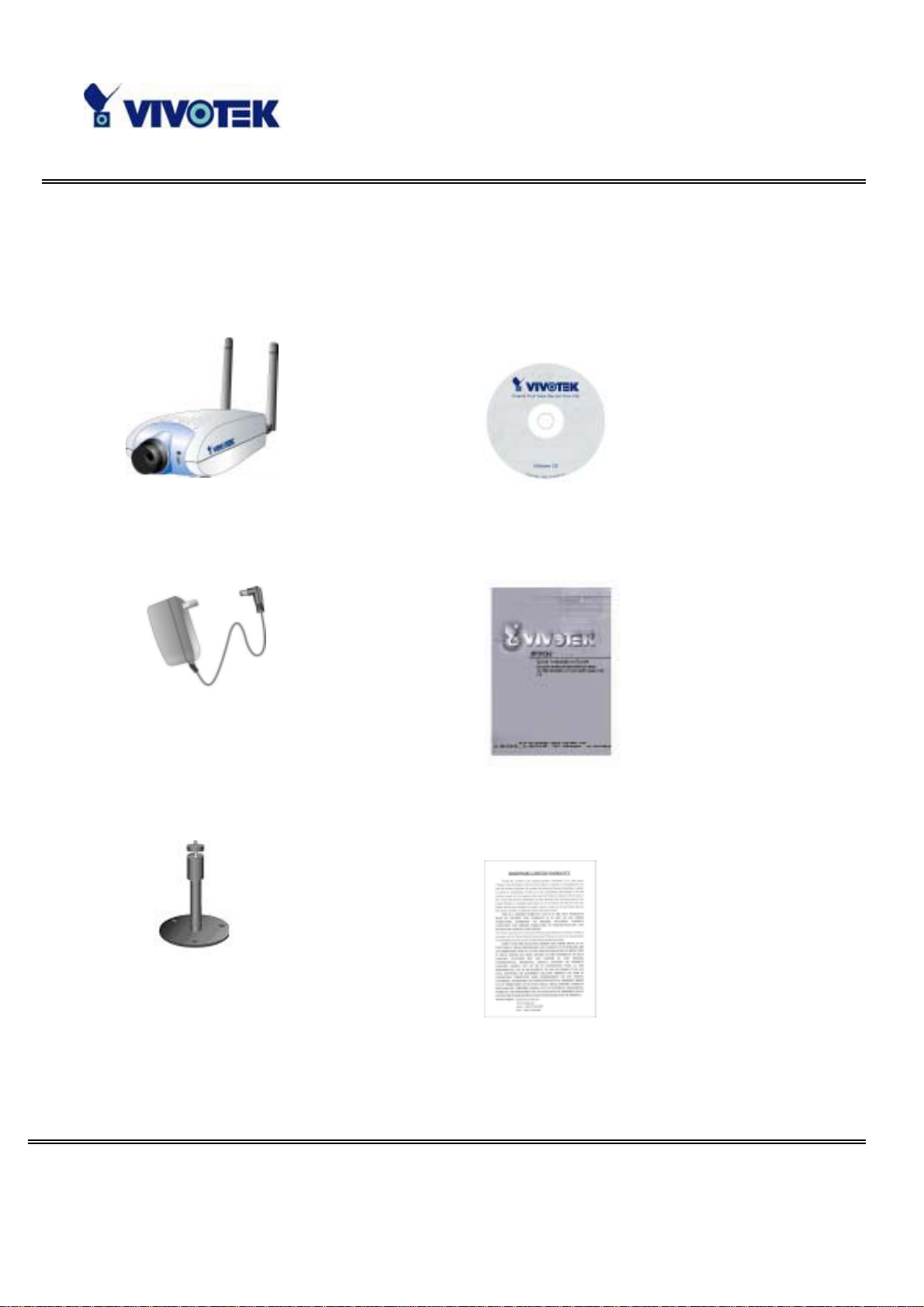
Package Co n tents
Network Camera IP3133
Power adapter
Software CD
Quic k insta llation guide
Camera stand
- 5 -
www.vivotek.com
T: 886-2-22404099
F: 886-2-22404097
Warranty card
Page 7
o
e
c
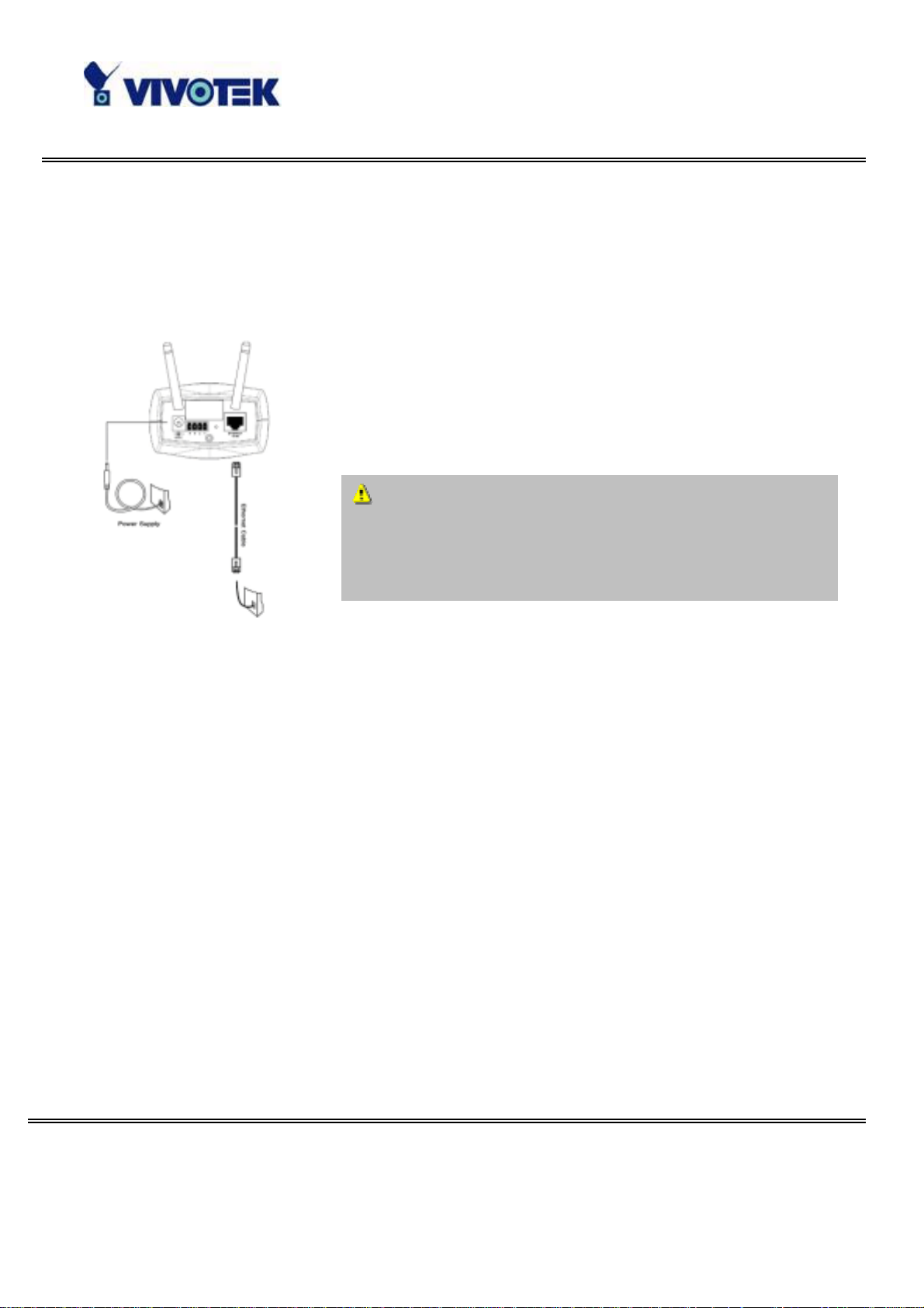
Installation
Hardware installation
All necessary accessories can be found in the product
pack ag e ex cept f or t h e E t hern et c abl e t hat depen d s on t he
user’s environment. The Ethernet cable should meet UTP
cate g ory 5 that cannot e xceed 100 meters.
C o nnec t the jack of the power adapter t
MiniAVServer prior to plugging the utility e nd i nto th
As s oon as the power adapter is plug ged into the utility socket, the f ront LED will switch
betw een gre en and red for sever al tim es. Afte r pass ing the self-test, the LED will shut
off and Network Camera will standby for software installation. Otherwise refer to
Appendix A for troubleshoo ting.
utility power socket. It will reduce accidental electri
surge shock.
To install in Ethernet,
Make sure the Ethernet is firmly connected to a switch hub. After attaching the
Et h ernet cable plu g i n t he power adap ter. If th e L ED t urns out t o be stead y green after
self-test, go to next paragraph “Software installation” . If the Ethernet is not availabl e,
Network Camera will s witch to wireless LAN mod e.
To install in wireless LAN,
If the Ethernet is not available while power o n , Ne two rk C ame ra will search fo r any
access point wit h the SSID “default” . Onc e an y access point is found, the LED will turn
green to wait for installation. If the network environment cannot meet the default
settings, install Network Camera in Ethernet to proceed with wireless LAN
- 5 -
www.vivotek.com
T: 886-2-22404099
F: 886-2-22404097
Page 8
config uration.
Network Camera will automatica lly de tect and o perate in the availa b le network
in terf ace with the priori ty of Ethernet tha n WLAN. Op eratin g in e ither network mode,
the LED will f lash every seco nd as heartbeat to indicate a live .
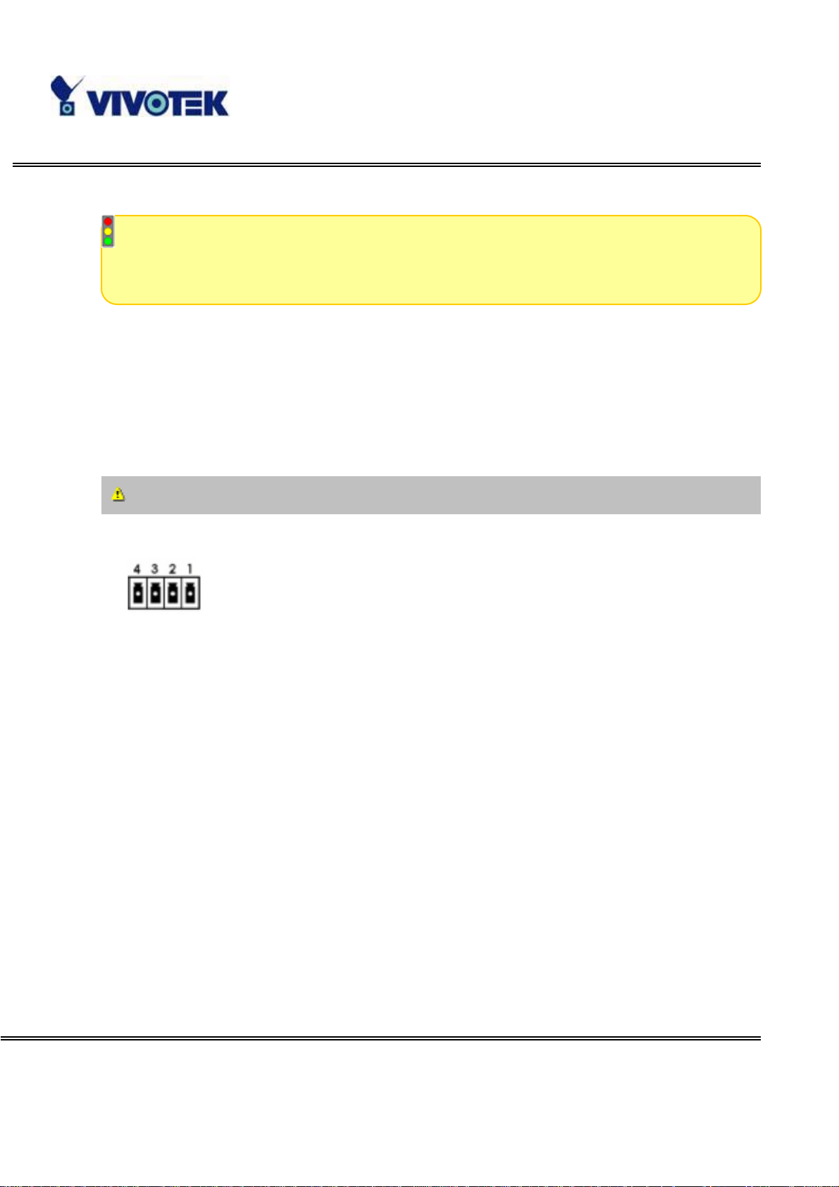
Network Came ra provides a general I/O terminal bloc k with one digital input and one
rela y swit ch f or d evi ce cont r ol. Pin 1 an d pin 2 c an be c on nected t o an e xternal sens or
and the state of voltage will be monitored from the initial stat e 'LOW'. Th e relay switch
of pin 3 and pin 4 can be used to turn on or off the ex terna l de vice.
Consult with the dea ler of the p eripherals f or correc t install ati on.
1 DI- INPUT (Initial state of DI is low)
2 DI+ INPUT (Max . 50mA, 12VDC)
3 SW_COM MON OUTPUT (open f rom SW_OPE N at initial st ate)
(close with SW_OPE N whe n set DO to ON)
4 SW_NOPEN OUTPUT (M ax. 1A, 24VDC or 0.5A, 125VAC)
- 7 -
www.vivotek.com
T: 886-2-22404099
F: 886-2-22404097
Page 9
Software installation
In the following content, "user" re fers to those who ca n a ccess Ne twork Camera and
"admi nistrator" refers to th e supe rvisor who c an configure Network Camera and grant
users access.
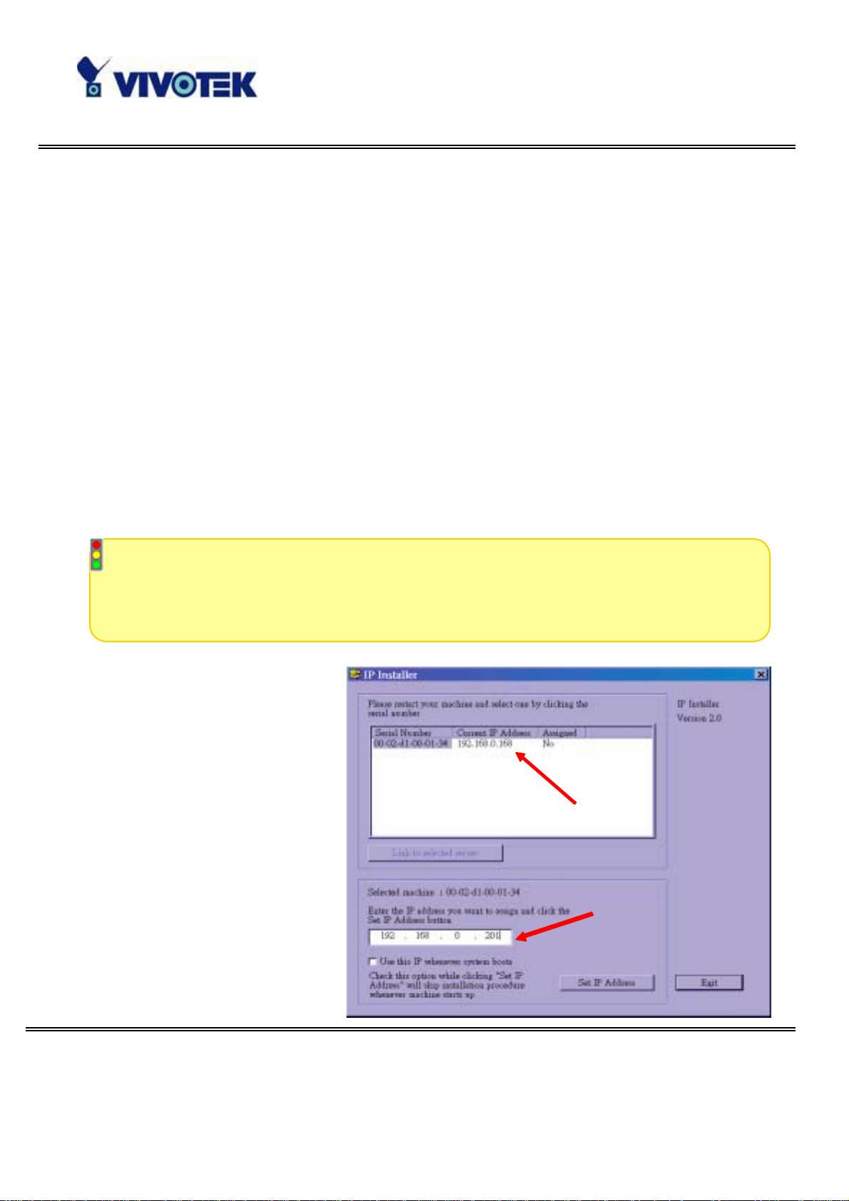
Wh en co m ple tin g the h ar dw are insta lla tio n, ad min istra tors need to run the I ns talle r
program included in the product CDROM to locat e the newly install ed Network Cameras.
Any Network Cam era standb y for softw are install ation will be captur ed by the Installer
prog r am. Theref ore t h e re m ay b e s ev er a l en tr ies s h ow n i n t h e wi nd ow . Admi ni st rat o r s
may differe ntiate the Netw ork Cameras with the serial number and cli ck on th e entry
wit h "Assigned" field l abel ed "No" t o perf orm softwa re install at ion. Th e s erial nu mber is
printed on the labels on the car ton and the rea r panel of Network Camera body.
To install Network Camera for wireless usage, it is recommended to install in
Ethernet first. After successfully entering the network configuration page, input the
correct W LAN s et t i ngs , remo ve t h e Et h e rnet cable an d r ecycl e t he p owe r t o work i n
WLAN.
The IP address shown in
"Current IP Address" field
depends on t he local netw ork.
It may get from the DHCP
serv er for the administrator's
reference . I f there is no DHCP
server, administrators can
choose any neighbor IP
address of the PC. The
Installer program will check
the I P a d dr ess au toma tica lly;
there will be a warning
message if it conflicts with
- 8 -
www.vivotek.com
T: 886-2-22404099
F: 886-2-22404097
Page 10

others. If adm inis trators wa nt to use ano the r IP address, modify the IP address text
field.
- 9 -
www.vivotek.com
T: 886-2-22404099
F: 886-2-22404097
Page 11
I f the ad ministrator wants to f ix the
IP address of the unit, check the
option "Use this IP whenever
system boots" to skip future
installation procedures. Otherwise
the unit will need installation
whenever it is restarted.
Click on “S et IP Address” butto n to
proceed.
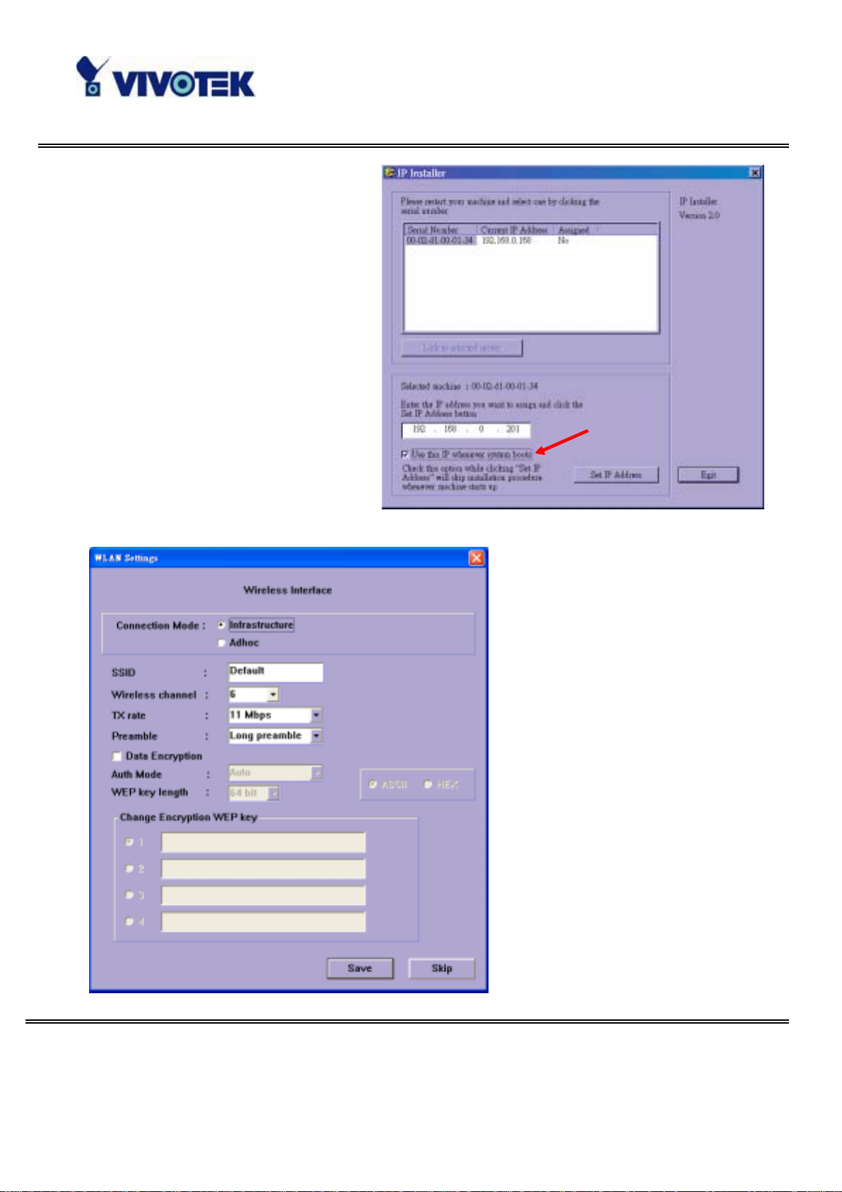
En ter the wire less LA N s etti ngs
according to the access point in
infrastructure or Ad Hoc master.
The connection mode, SSID,
WEP settings are required. If
the settin gs are not sure a t this
stage, click “Skip” to continue
installation in Ethernet. All the
settings can be entered later
from the web configuration
page.
- 1 0 -
www.vivotek.com
T: 886-2-22404099
F: 886-2-22404097
Page 12
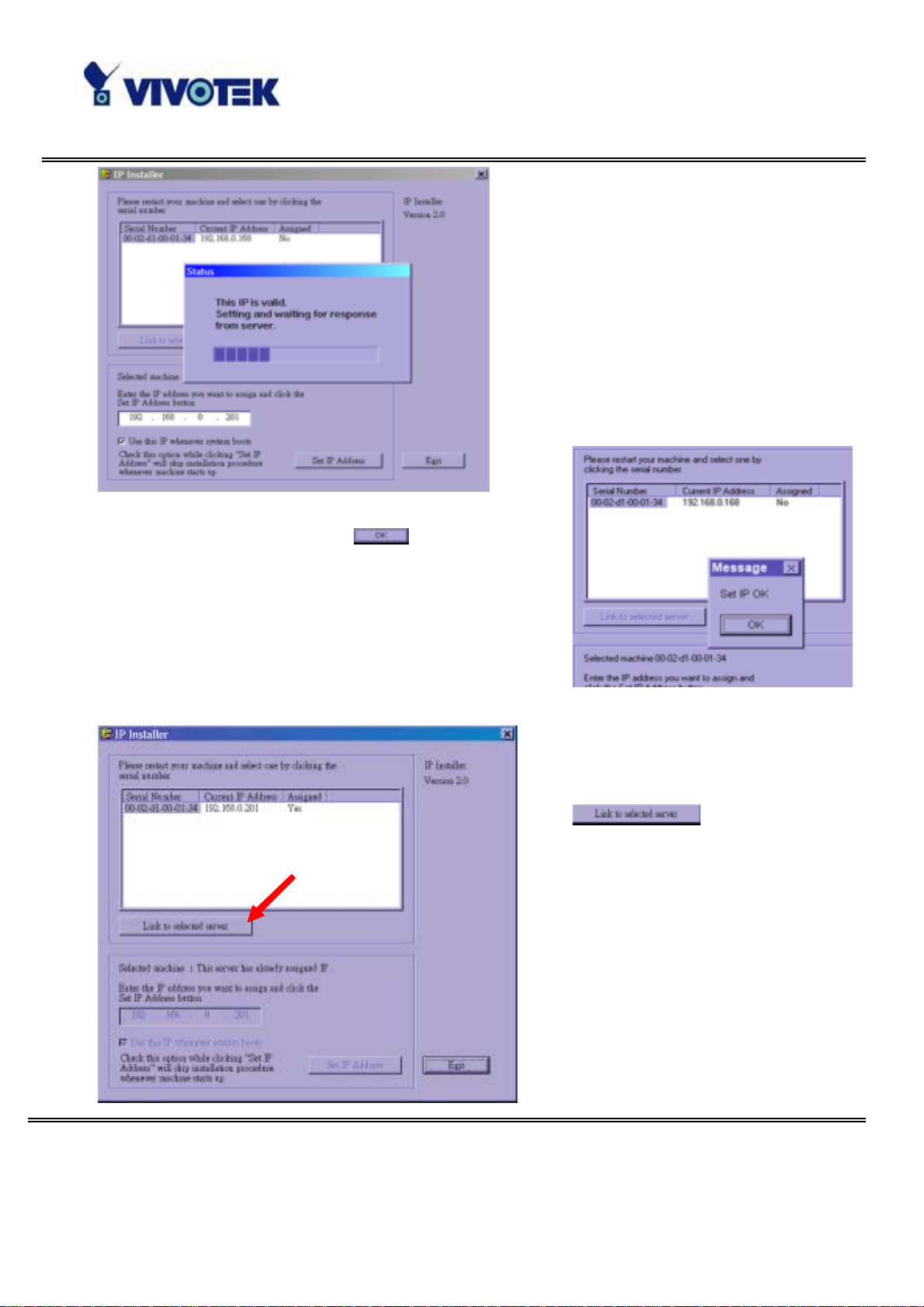
After clicki ng on “S ave”, a progressive
bar will indicate the installation
process.
Cong ra tula tio ns ! Now Network Camera i s ready
for acc es s. Aft er clicki ng on
in the successful
dialog, the "Assigned" field will be labeled "Yes".
Administrators should keep the address information
for users’ reque st.
If there is any error dialog rather than “Set IP OK”,
please follow the next page.
Administrators may click directly
on
newly installed server in the
default browser.
to access the
- 1 1 -
www.vivotek.com
T: 886-2-22404099
F: 886-2-22404097
Page 13
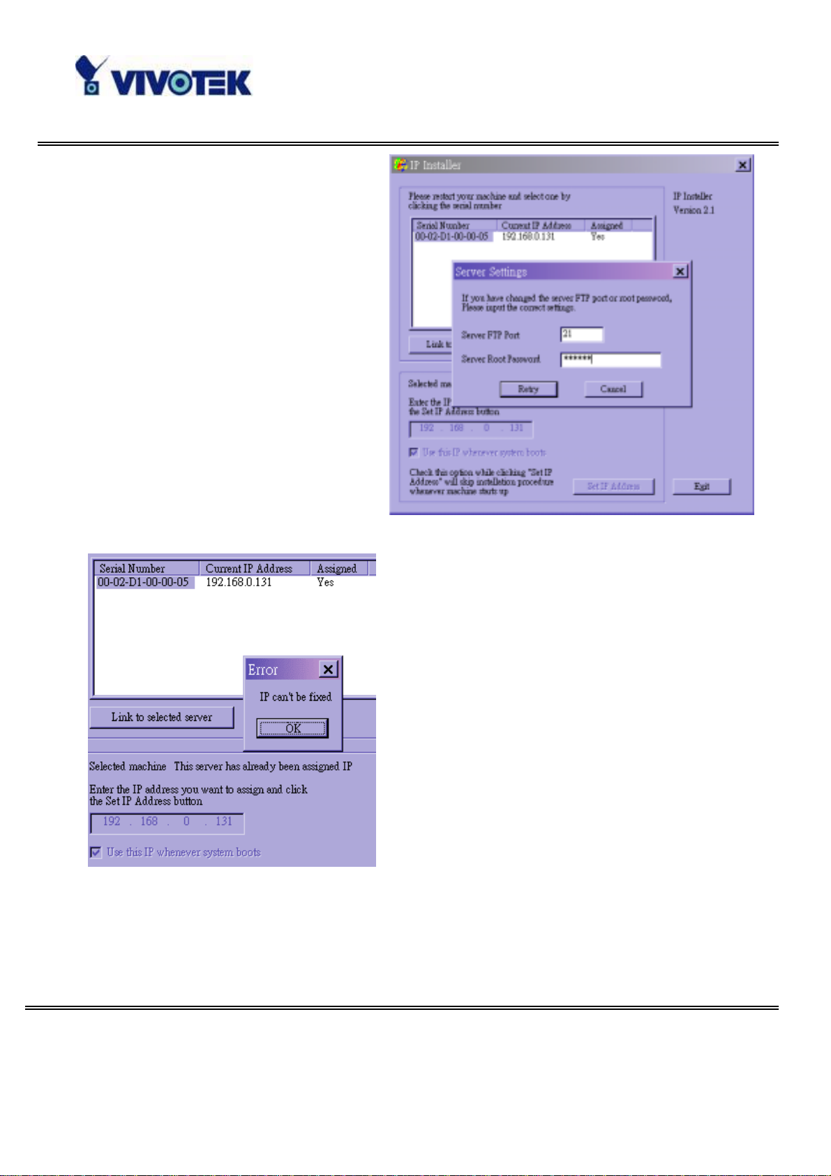
When administrators choose “Use
this IP whenever system boots” or
fill any wireless network settings,
the local FTP server port and root
password of Netwo rk Camera will be
utilized. If they have b een changed
prior to the installation, a
con f irmation window will pop out to
request correct settings. After
ente ring the correct settings, press
“Retry”.
If the “Server FTP Port” or “Server Root
Pas sword” is lost, click “ Can cel” to exit. In this
case, the IP address of Network C amera will
still be installed though it is not fixed for
furt her re boot . If t h e root passw o rd is correct ,
a dmin istrator can l og in to browse the correct
local FTP server port in the network settings.
Oth erwise re f er to Appen di x A T r ou bleshootin g
to restore factory default settings and then
use the installer to install ag ain.
Once installation is complete, administrators should proceed to the next
section "First access to Network Camera" for necessary checks and
configurations.
- 1 2 -
www.vivotek.com
T: 886-2-22404099
F: 886-2-22404097
Page 14

First access to Network Camera
Check n etwork settings ev en if connected alread y
A ltho ug h Ne twork Camer a alre ady ca n be co nn ecte d a fte r so ftwar e ins ta lla tio n f rom
Local Area Network, administrators should complete the network settings in the
configuration page including the corre ct subne t mask a nd IP address of gateway and
DNS. Ask for the network administrator or Internet service provider for the detail
infor mation. By defa ult Ne twork Ca mera will need a dminis trator 's installation every
time it reboots. If the network settings are sure to work all the time, disable the install
option . Refer to “Network setti ngs” in system confi guration page f or detail s. Once any
setting is entered incorrectly and thus hangs Network C amera, restore the factory
settings according to the steps in troubleshooting.
Add password to protect from offense fro m strangers
Since the administrator’s p assw ord is blank by d efault, Network Cam era will not a sk for
any password. However the administrator should change the password as soon as
possible t o prote ct fro m n etw or k int rude rs. Once t he admin istrat or ’s pa ssw o rd is s av ed,
Network Camera always needs user name and password before access. The
administrator can setup at most twenty use r accounts. Each user is able to access
Network C amera ex cep t f or sys tem configuration. S om e c ritica l functions are lim ite d
only fo r ad ministrator s su ch as s yst em confi gu rat ion, us er admi nist r at ion an d soft wa re
upgrade. The user name of the administrator is assigned to “root” permanently. Once
the p ass wo rd is ch anged , the browser wil l di sp la y an au thenti cation win do w to ask for
the new password. Ther e i s n o wa y to disco v er adm i nist r ator’s p a ssw ord. If t he
pas s word is for g o tten, only r estor ing factor y de faults ca n he lp .
- 1 3 -
www.vivotek.com
T: 886-2-22404099
F: 886-2-22404097
Page 15
How to Use
Authentication
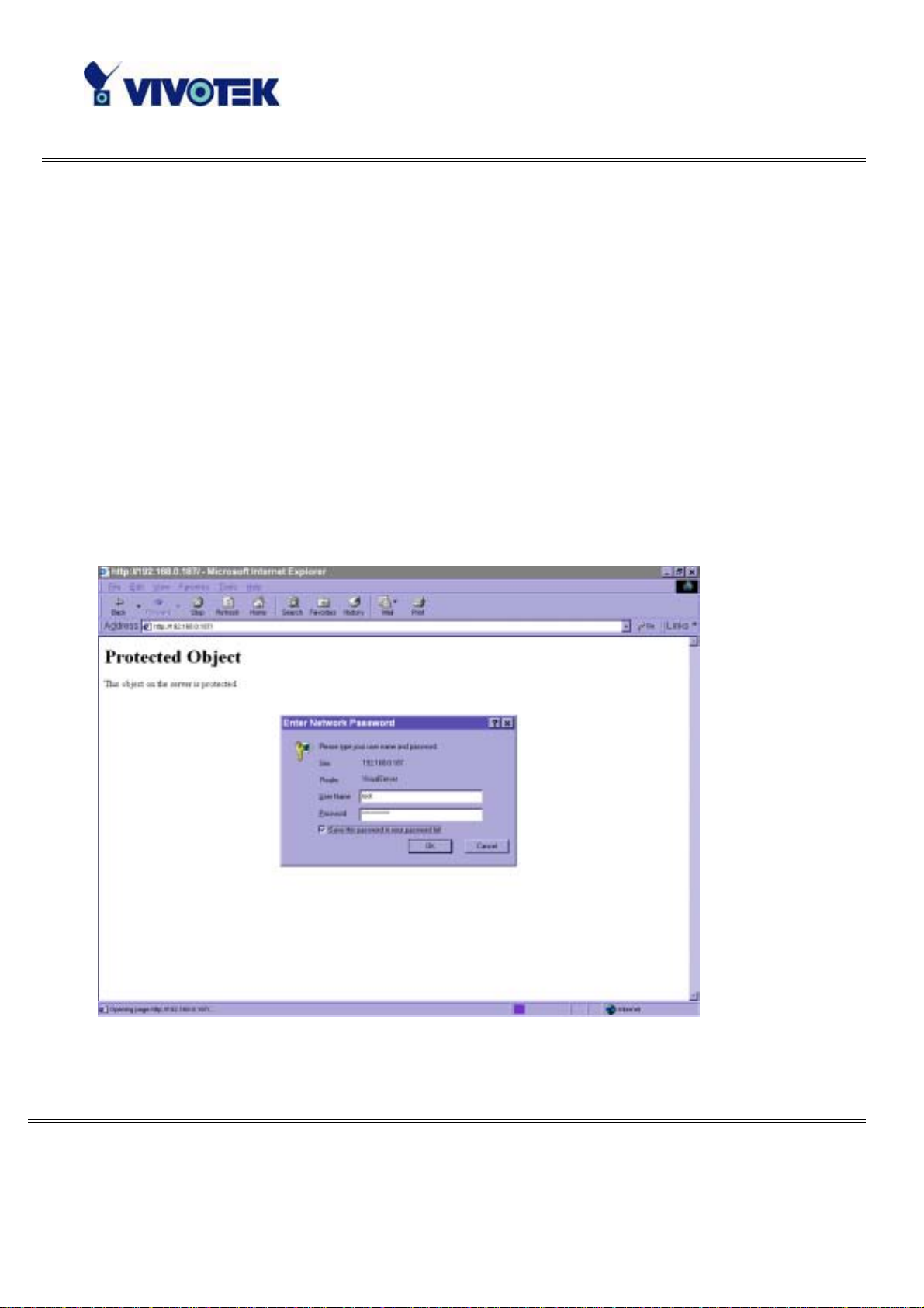
After opening the Web brows er a nd typing in the URL of Network Camera, a dia logue
window ma y p op up to requ est a use rname a nd pa ssword e xc ept th at th e administ r ator
does not save any password. Upon successful authentication, the main page will
display like the figur e be low.
In the figure, the foreground is the login window and the background shows the
message when authentication fails. The user may check the option to save the
passwor d fo r futur e conv enience.
- 1 4 -
www.vivotek.com
T: 886-2-22404099
F: 886-2-22404097
Page 16
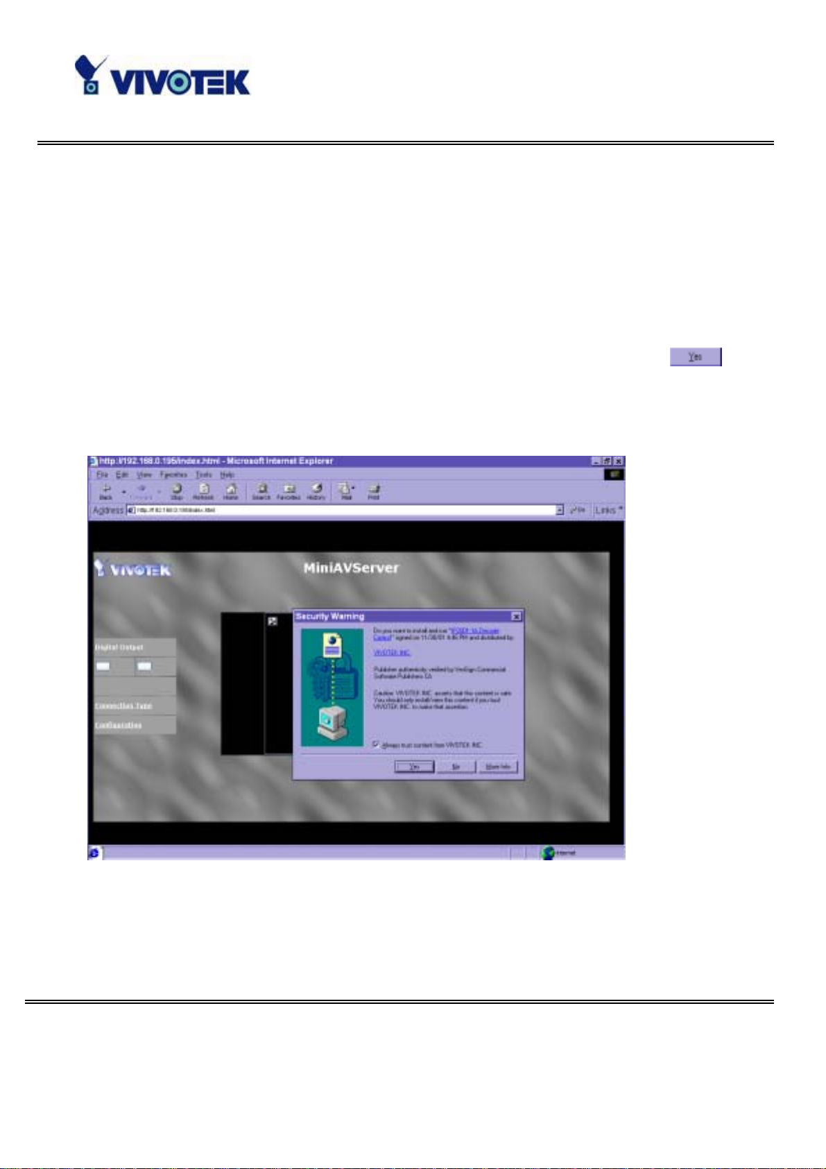
Installing plug-in
If it is initial access to Network Camera in Windows, the web browser may prompt fo r
permission to install a new plug-in that is provided by Ne twork Ca mera. Prompt or not
and the prompt message depend on the Internet security settings of user’s PC or
notebook. The highest security level may prohibit any installation and execution
attempt even the plug-in is safe. This plug-in has been registered for certificate and is
us ed to d is pl ay th e moti on ed pi ctu res in the bro wser. Us er s ma y c lic k on
to
proceed. If the web browser does not allow the user to install, check the Internet
security option to lowe r se curity le vels or contact network supervisors.
- 1 5 -
www.vivotek.com
T: 886-2-22404099
F: 886-2-22404097
Page 17
Primary user’s capability
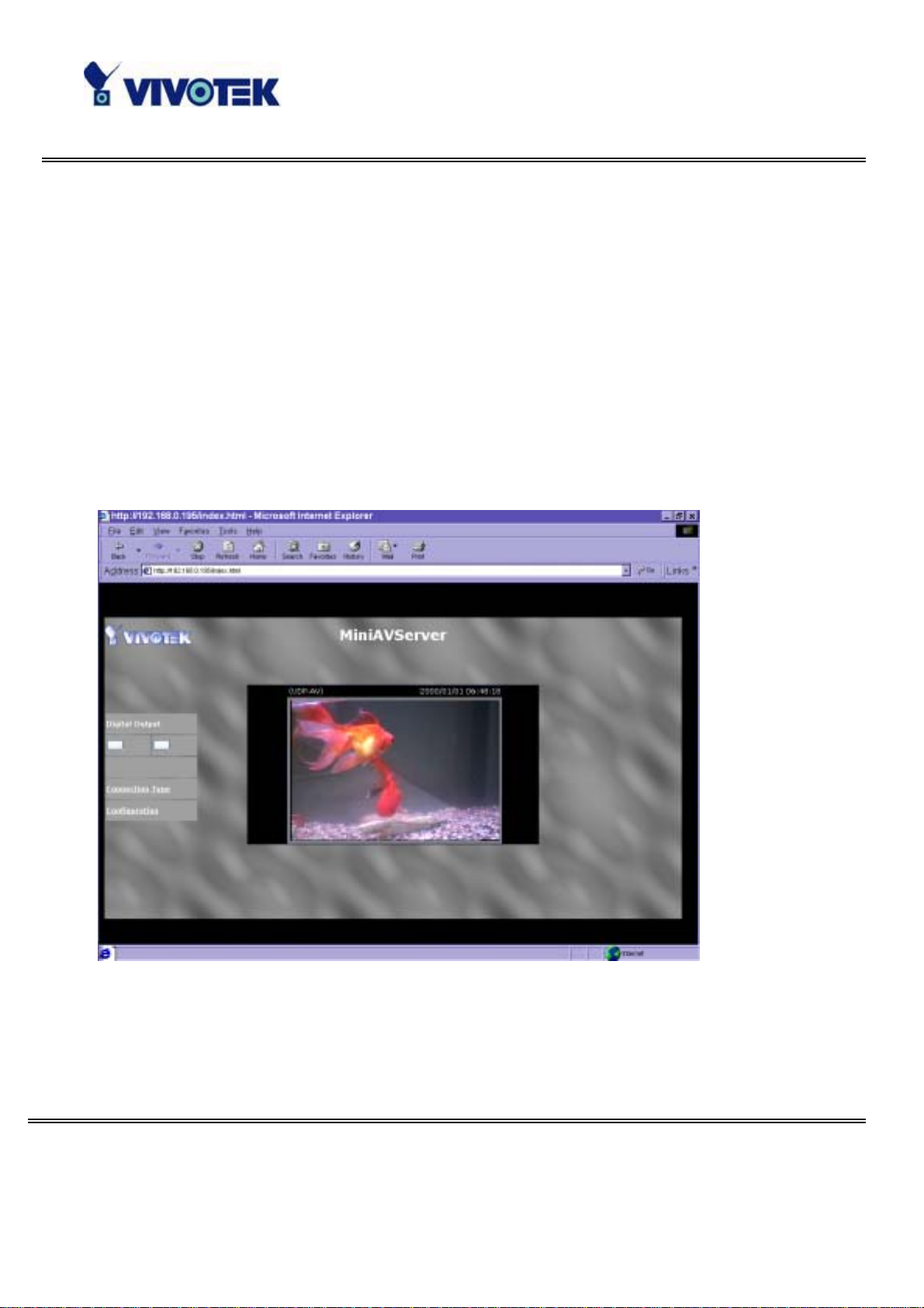
Main screen with camera view
There is a logo image shown in the upper left corner. It can link to other web sites or
resou rce s dep endi ng on th e s ett ing s in conf ig u ration . The assi gn ed c apt ion and sy st em
date/time will display in the banner above the image window. There might be some
win dows enclosed b y red l in es sh own i n t he image as s oon a s mot ion is detected in th e
re la te d w ind ows. C l ick on th e co nfi gu ra tio n l ink to the ri ght of th e im age w indo w to
enter the c onfiguration page.
- 1 6 -
www.vivotek.com
T: 886-2-22404099
F: 886-2-22404097
Page 18
C onnection type
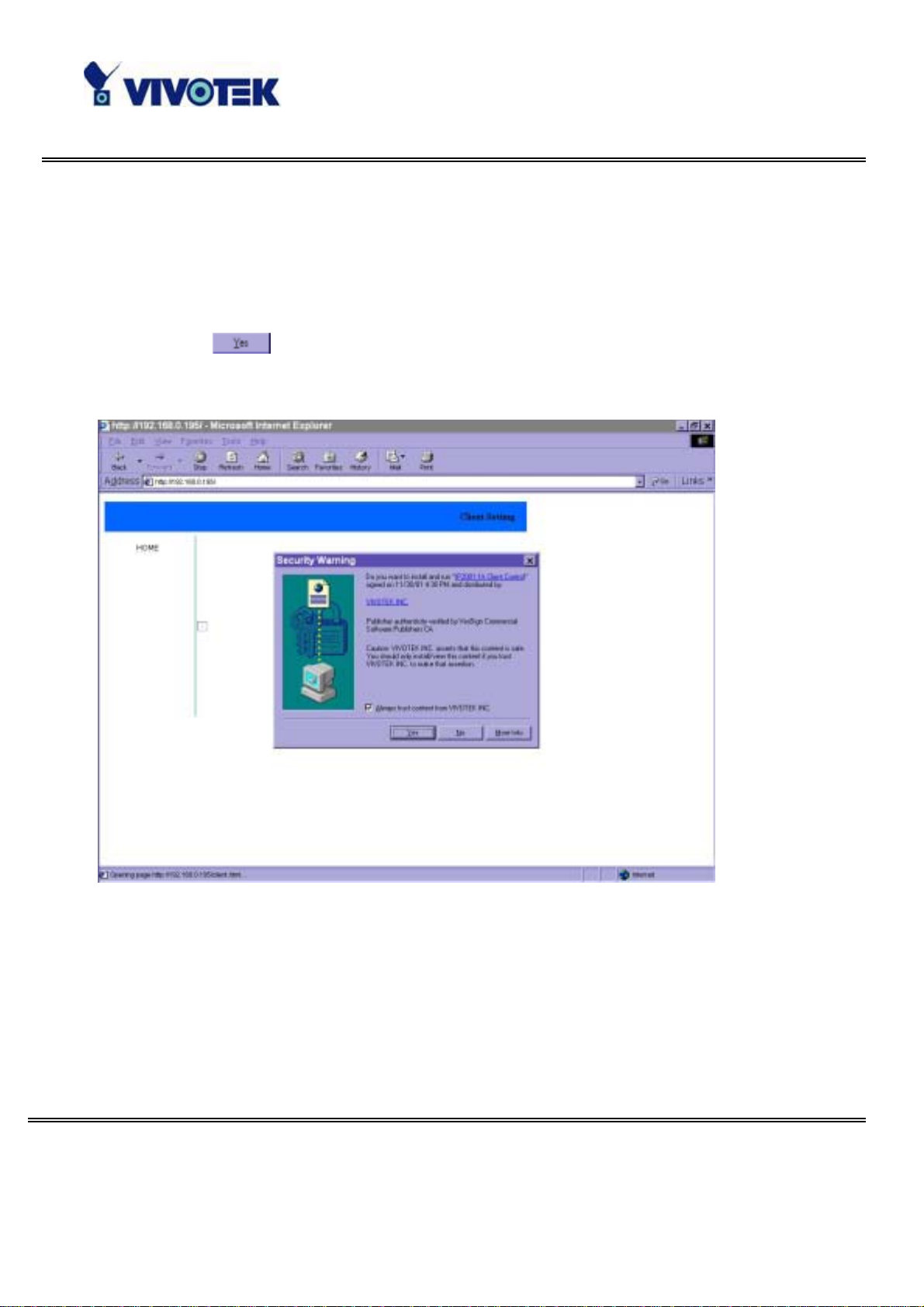
If it is t he fi rst acce ss t o “Conn ect ion type” pag e in Win dows, th e web brow ser will ask
to install a ne w plug-in that is provided by Network C amer a. This plug-in has bee n
regist e red fo r cert ificat e and is used t o change t he pa ram eters at t he clien t si de. Use rs
may click on
to install the plug-in. If the web bro wser does not allow th e user
to i ns tal l, c heck the I nte rne t secu ri ty to lo we r the sec uri ty leve l or co nta c t ne twork
supervisors.
There are two settings for the client side. One is “Me dia Option” for users to
determin e if the audio sh ould be mut ed. The oth er is “P r ot o col O pt ion” to ch oo se th e
connection protocol between client a nd server. There are three protocols to optimize
your usage - UDP, TCP an d HTTP. Wit h U DP p rot oc ol, audio and vi d eo st r ea ms can be
more real-time. But some packets may be lost due to network burst traffic and images
will be o bscure. I f TCP pro to co l is selected, p acket los s would no t occur and v ideo
- 1 7 -
www.vivotek.com
T: 886-2-22404099
F: 886-2-22404097
Page 19
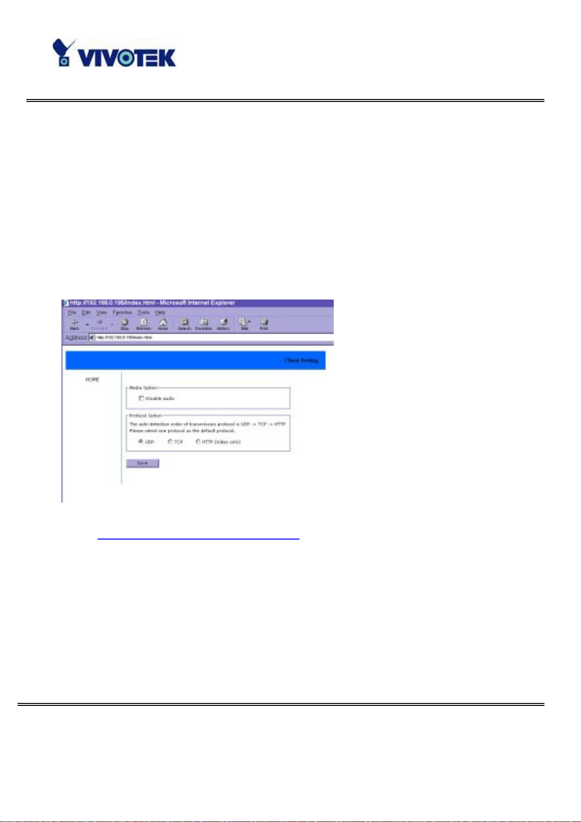
display will more accurate. But the real-time effect is worse than UDP protocol. If the
net work is p rote ct ed by a fi r ewall a nd i t op ens HTTP port (80 ) only, HTTP p rotocol mu st
be selected. In this mod e, audio will not be sent and you can see the video only . If you
have no special ne eds and no idea to choose one among them, simply choose UDP.
Generally the client will automatic ally try these protocols b y the f ollowing order, UDP →
TCP → HTTP. After the cl ient connects to th e Netw ork Camera succe ssfully, “Protocol
Option” will show the work ing protoco l. The cho se n pro tocol will be r ecorded in the
user 's PC an d used f or next con ne c ti on . If the net work en viron m en t is change d or u se rs
wa nt to le t we b br owse r de tec t a ga in, se lec t UD P ma nu al ly to sav e and the n re tur n
HOME to connect again.
<url>
http://<Network Camera>/protocol.html
<Network Camera> is the d omain name o r o rigina l IP addr ess of Network Cam era.
- 1 8 -
www.vivotek.com
T: 886-2-22404099
F: 886-2-22404097
Page 20
Administrator’s capability
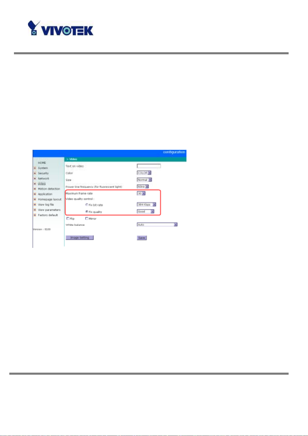
Tune the b est performance
The best performance means the image refresh ra te should be the fa stest as possible
and the vide o quality should be the best a s possible at the lowest network bandwidth
as possible. Three factors, “Maximum frame rate”, “Fix bit rate”, and “Fix
quality ” in the Video config uration p age, ar e co rrelative to the perf orm ance.
My priority is real-t ime mo tioned images
To achieve the real-time visual effect, the network bandwidth should be large enough
t o t ransmi t 20 imag e frames or m ore. If you ar e i n t h e bro ad b an d net w o rk ov er 1 Mbp s,
yo u can f ix the bit ra te to 1000Kbp s or 1200Kbps , or fix the q uality to a chieve the
ma ximum fra mes. The max imum fr am e rate is 25 in 50Hz sy stem and 30 in 60Hz
sy stem. I f your network band width is mor e than 384Kbps, you can fix the bit rate
according to your bandwidth and set the maximum frame rate to 25 or 30. If the
images vary dramatically in your environment, you may slow down the maximum
frame rat e to 20 to decrease the transmitted data for better video quality since human
coul d n ot easily tel l t h e dif fer en ce bet ween 20 and 25 or 30 f rames pe r sec on d. If y ou r
ne two rk b an dwi dth is be low 384 Kb ps , yo u s ho uld fix th e bit ra te a c cord ing to your
- 1 9 -
www.vivotek.com
T: 886-2-22404099
F: 886-2-22404097
Page 21

ban dwidth a nd try out th e best performance by tuning the maximum frame rate. The
lar ger fra me rate in s low ne twork will blur the images. Yo u ma y a lso try to cho os e
“H al f” i n s ize op t ion for bet t er i m ages o r “H al fx2” for l arge r i mage si ze. N ot e t hat ev en
yo u have well tuned th e para mete rs, the performance may still vary from pe rson to
person when multiple users view at the same time. Because the network has burst
constraint and everyone’s environment is not the same, any poor conn ection will drop
the normal performance.
My priority is clear identification for each imag e
To have the best v ideo quality, yo u should fix the quality to detailed or excellent and
tune the maximum fra me rate to suit for yo ur ne two rk bandwidth. If you get some
brok en pi ctu re s in sl ow net work, you can choose T CP p rotocol in “Conn ecti on t yp e” for
more accurate transmission but the recei ved images may have certain time delay. Note
that any slow connection in multiple us ers will dro p the prope r pe rforma n ce.
I want to compromise between real-time and clear images
If you have a broadband network, choose fix qu ality to normal or better rather than fix
bandwid th. Otherwise fix the b andwidth according to your actual network speed a nd
set the fra me rate to 30. If the ima ges look bad, se lect the lo wer frame rate above 15.
If the images are not improved, select the lower bandwidth.
- 2 0 -
www.vivotek.com
T: 886-2-22404099
F: 886-2-22404097
Page 22
Open accounts for users
Protect Network Camera by passwords
Netwo rk C amera is shipped without any pa ssword by defa ult. That me ans everyone
can access Network C amera including the configuration as lo ng as the IP address is
known. It is necessary to assign a password if Network Camera is intended to be
1
acce sse d by ot hers. T yp e a new word t wi ce in ○
t o enabl e p r otect ion . This pa sswor d i s
used to identi fy the administrator. Then add an ac count with user name and pas sw ord
2
for your friends in ○
. Network Camera can provide twenty accounts f or your valuable
customers or friends. Each account identifies the access right rather than the real
visitor. That allows multiple visitors share the same account of different level. An
opt ion t o acce ss DI/ DO is pr ovided for each a ccou nt . So me us ers m ay ne ed t o prohi bit
3
from controlling your attached dev ices . You may d elete some users fr om ○
.
4
○
More flexible options for viewers
The f ir st o pt i on al low s anyone u s es “dem o” as t h e u s er n ame to vi ew w it h out passw o rd .
A dm ini strato r s ca n a ls o dec ide if mo re v ie wer s are all ow ed to wa tch the v ideo if the
viewers exc ee d the limit. The overloaded viewers will have snaps h ot mo d e instead .
- 2 1 -
www.vivotek.com
T: 886-2-22404099
F: 886-2-22404097
Page 23

Change homepage layout
How to change the subject text of homepage
1. Click on “Configuration” on homepage,
2. Chan ge the text in “Host name”,
3. Clic k on “Save ” b u tton.
- 2 2 -
www.vivotek.com
T: 886-2-22404099
F: 886-2-22404097
Page 24

How to change t he font color
1. Click on “Configuration” on homepage,
2. Clic k on “Ho mepage layout” at the left column,
3. Find “Font color” and p u ll d own the list to ch oose a ny color you like ,
4. Clic k on “Save ” b u tton.
* The font c ol or is b etter to c on trast with the background.
How to change the background
1. Click on “Configuration” on homepage,
2. Clic k on “Ho mepage layout” at the left column,
If you want to display simple co lor without any image ,
3. Find “Background graph” and choose “bla nk”,
4. Find “Back g round colo r” and pull down the list to choose any colo r you like,
5. Clic k on “Save ” b u tton.
* The ba ckg round color is better to c on trast wi th the font.
- 2 3 -
www.vivotek.com
T: 886-2-22404099
F: 886-2-22404097
Page 25

If you wa nt to use the ima ge from a nother we b site as backgro und ,
3. Find “Background graph” and choose “Url”,
4. Type the URL of the image on the Internet in the edit box, for example,
“http://dgl.microsoft.com/thumbnails/j023/j0235217(t).gif”,
5. Clic k on “Save ” b u tton.
If yo u want to change the default backgr o und ima ge stored in Network Ca m era,
3. Find “Background graph” and choose “default”,
4. Clic k on “Save ” b u tton,
5. Prepare an image file with size less than 131000 bytes and r ename it to wallppr.jpg,
6. Open an FTP client program and c onnect to Networ k Camera. The user name and
password is as sa me a s the administrator’s.
7. Trans f er wallppr.jpg in local folder to Ne twork Camera,
8. Close the FTP program and re load the homepage of Network Ca mera .
- 2 4 -
www.vivotek.com
T: 886-2-22404099
F: 886-2-22404097
Page 26

How to change the image logo at the upper left corner of homepage
1. Click on “Configuration” on homepage,
2. Clic k on “Ho mepage layout” at the left column,
If you want to remove any logo,
3. Find “Logo graph” and choose “blank”,
4. Clic k on “Save ” b u tton.
If you wa nt to use the ima g e from another web site as logo,
3. Find “Logo graph” and choose “Url”,
4. Type the URL of the image on the Internet in the edit box, for example,
“http://dgl.microsoft.com/thumbnails/j023/j0234430(t).gif”,
5. Clic k on “Save ” b u tton.
If yo u want to change the default logo stored in Network Ca m era,
3. Find “Logo graph” and choose “de fault”,
4. Clic k on “Save ” b u tton,
- 2 5 -
www.vivotek.com
T: 886-2-22404099
F: 886-2-22404097
Page 27

5. Pr epa re an ima g e file with size less than 65000 by te s and rename it to logo.gif,
6. Open an FTP client program and c onnect to Networ k Camera. The user name and
password is as sa me a s the administrator’s.
7. Trans f er logo.g if in loca l folder to Network Camera,
8. Close the FTP program and re load the homepage of Network Ca mera .
If yo u want to add hyper link to the logo image ,
3. Find “Logo link” and type the hyperlink in the edit box, for example,
http://www.yahoo.com,
4. Clic k on “Save ” b u tton.
- 2 6 -
www.vivotek.com
T: 886-2-22404099
F: 886-2-22404097
Page 28

g
py
How to design my own homepage to replace the current one
1. Prepare your own homepage with size less than 65000 bytes and rename it to
use r.htm,
2. Insert the htm l codes o f video obj ect, the bold Italian text in the following example,
in to th e appropriate positi on in user. htm . Note that the codes of vide o object mu st be
copied exactly the same including the letter case.
****** Example homepag e be g in ******
<html>
<head>
<title>Exa mple – custom homepag e</title>
</head>
<body bac kground="/pic/wallppr.jpg">
<p>
<a href="/setup/config.html">
<im
align="le f t" width="64" height="64">
</a>
<font size="7" face="Comic Sa ns MS" color="#FF0000">
MiniAVServer Demo
</font>
</p>
<p alig n="left">
<!-- Co
MiniAVServer. This line is remark only and is hidden on homepage. //-->
<OB JECT ID=VAMCtrl></OBJECT>
</p>
</body>
</html>
****** Example homepag e e nd ******
src="http://dgl.microsoft.com/thumbnails/j023/j0234430(t).gif"
the next bold line to where you want to show the image c omi ng fr o m
- 2 7 -
www.vivotek.com
T: 886-2-22404099
F: 886-2-22404097
Page 29

ge
e
3. Open an FTP client program and c onnect to Networ k Camera. The user name and
password is as sa me a s the administrator’s.
4. Trans f er user.htm in local folder to Networ k Camera,
5. Close the FTP program and re load the homepage of Network Ca mera ,
6. Click on “Configuration” on homepage,
7. Clic k on “Ho mepage layout” at the left column,
8. Check “Use the customized homepage”.
9. Click on “Sa ve” button a nd r eturn to hom epage .
* The user.htm only provides plain text content that scripts and URL of external
resourc es c an be used to adorn th e homepage . Refer to tu torials of writin g HTML and
scripts.
If the customized homepage goes wrong and cannot display, link to the “Homepa
layout” page, “http://<IP address of MiniAVServer>/setup/layout.html”, to disabl
“Use the customized homepage”.
- 2 8 -
www.vivotek.com
T: 886-2-22404099
F: 886-2-22404097
Page 30

Build a multimedia we b attract ion s ite
Show off to my friends – mid-scale service
Network Camera can allow ten visitors on-line simultaneously. Just follow the
installation, focu s Network Camer a on any view you would like friends to shar e and tell
the m th e ad dr ess to typ e i n the we b br owse r. O f c o ur se yo u hav e to m ai nta in yo ur
friend list in the secur ity configuration page to filter unexpected strangers. No need to
have the g ee ks’ skill and e q uipme nts, no need to find suitable software.
Show my products or scenic spot for e-business – large-scale service
If t he visit or s ma y e xceed t he ac cou nt limi t, Net work Cam era can su ppl y e xt ra viewe rs
the homepage of snapshot mode that will have the JPEG still image refreshed
periodically and automatically. It needs script function s upported by the web browser.
1. Click on “Configuration” on homepage,
2. Clic k on “Se curity” at the left column,
3. Go to the page bottom and check “Allow more v ie we r s with snapshot mode”,
4. Se t the sna psho t inte rval to refresh the still image automatically. The lon ger the
snapshot interva l is, the better the snapshot mode works for more viewers.
- 2 9 -
www.vivotek.com
T: 886-2-22404099
F: 886-2-22404097
Page 31

If you want to expa nd the v iewers tre mendously, hos t a powe rful we b site that c an
handles large netwo rk tra ff ic and attr act eyeballs with the pictur e refres hed often by
Ne twork Ca mera.
If the web space has FTP service,
Se tup N etwork Camera as an FTP client to upload the pi ctures. The advan tage is the
access of Network Camera is independent of the viewers to ensure the quality.
1. Click on “Configuration” on homepage,
2. Clic k on “Network” at the le f t column,
3. Fill the FTP related settings including server , u ser nam e and password, as well as the
upload path if spe cifie d b y the web sp ace,
4. Click on save and wait for system restart,
5. Clic k on “Application” at the left column,
6. Select the weekday and daily schedule you want to upload the pictures,
7. Select “Sequential ope ration” and set the interva l,
8. Sel ect FTP with ou t date time s uffix as the u pload method a nd cl ick on save,
9. The image file uploaded to the web space is named “video.jpg”. Check if the file is
- 3 0 -
www.vivotek.com
T: 886-2-22404099
F: 886-2-22404097
Page 32

successfully uploaded to the correct fo lder,
10. Prepare a homepage with the embedded image reference to the image file
uploaded via FTP in advance.
If the web space has no FTP service,
An auto-refresh homepage c an be use d to pe riodically poll the ne west image from
N etw ork C ame ra. It is mostl y usefu l i n t h e fr ee w e b s pac e p r ovi d er as t h eir F TP se rvice
ma y be limited to use.
1. Prepare an auto-refresh homepage like the following example. The URL of image is
http://“IP address of Network Camera”/cgi-bin/video.jpg. Modify the IP address
a ccordin g to your Network Camera. Also def ine th e refres h interval according to your
network b andwidth for best effect. T o o frequ ent ref resh rate for a great deal of visito rs
may overload Network Ca me ra a nd retard the response.
- 3 1 -
www.vivotek.com
T: 886-2-22404099
F: 886-2-22404097
Page 33

g
ge
(
****** Example homepag e be g in ******
<html>
<head>
<title>Exa mple - auto refresh</title>
</head>
<body bac kground="/pic/wallppr.jpg">
<p alig n=left>
<font size="7" face="Comic Sa ns MS" color="#FF0000">
MiniAVServer Demo
</font>
</p>
<p alig n=left>
<!-- Be
in of sc ripts to auto refresh the image. Change t he I P ad dr es s in t he i m a
URL and refres hrate if necessary. //-->
<script language=java script>
var image="http://192.168.0.203/cgi-bin/video1.jpg"; //IMAGE URL
var refreshrate=5; //SECONDS BETWEEN REFRESH
var imgwidth=352; //IMAGE WIDTH
var imgheight=240; //IMAGE HEIGHT
function refresh(){
doc u ment.images["pic"].s rc=image+"?"+new Date();
se tTim eout('refresh()', refreshrate*1000);}
document.write
'<img src="'+image+'" height="'+imgheight+'"
width="'+imgwidth+'" nam e="pic">');
if(document.images)window.onload=refresh;
</script>
<!-- End of sc ripts to auto refres h the image. //-->
</p>
</body>
</html>****** Exa mple home p age end ******
- 3 2 -
www.vivotek.com
T: 886-2-22404099
F: 886-2-22404097
Page 34

Build a se curity a pplication
A dm ini strato r s c an com bine op tio ns on the a ppl ic ati on pa ge to per fo rm m any usef ul
security applications. There are
two trigger sources coming from
attached devices and/or motion
detection. There are also two
kinds of actions responding to
events including uploading
snapshots over internet and
driving attached devices. To
upload the snapshots, users can
choose wither email or FTP
according to user’s needs. Both
e-mail and FTP use the network
settings on the netw ork page. Refer to the d efinition sectio n fo r detail config ura tion.
1. Click on “Configuration” on
homepa ge,
2. Click on “Application” at t he left
column,
3. Check the weekdays as you
need and give the period of
"Snapshots begin" time and
"Snap shot s end" time to monitor
the trigger conditions every day,
4. Check the “Event operation”.
The trigger condition c an be set to
detected motion or status of the
attached device,
5. Set the delay be fore de te cting nex t eve nt to avoid continuous false alarms
- 3 3 -
www.vivotek.com
T: 886-2-22404099
F: 886-2-22404097
Page 35

following the o rigina l ev ent,
6. Set the delay to ta ke sn ap shot s after event to capture the direction of the moving
objects,
Send snapshots when motion is detect ed
If no external sensor is available, administrators can utilize the built-in motion
detec tio n to monitor any abnorma l movem ent and then send ema ils with snapshots
included for security check .
7. Clic k on “Moti on d etec ti on” at the left column,
8. Check “Enable motion detection”,
9. Click on new to have a new window to monitor vide o,
10. Type in a na m e to identify,
11 . Use mouse to d rag the wi ndow corner to resize o r th e title b ar to move,
12. T une the “Sensitivity” and “Percent age” accordin g to the local envi ronment. The
higher sensitivity, the easier motion is detected. The higher percentage, the more
difficult to dete ct small moving objects,
13. Click on save will enable the activity display. Green means the motion in the
win do w is un der th e w ater mar k se t by a dm ini strato r s a nd red me a ns it is ove r the
watermark,
14. Clic k on “A pp lic ation” at the left column,
15. Check the window name set in step 10,
16. Check “Upload snapshots while motion dete cted”,
- 3 4 -
www.vivotek.com
T: 886-2-22404099
F: 886-2-22404097
Page 36

If emails with snapshots are preferred,
17. Check “Send snapshots by email”,
18. C lick on save to validate.
If emails with snapshots are preferred,
17. Check “Send snapshots by email”,
18. C lick on save to validate.
- 3 5 -
www.vivotek.com
T: 886-2-22404099
F: 886-2-22404097
Page 37

e
t
Software revision upgrade
Customers can obtain the up-to-da te softwa re from Vivotek web site . An ea sy-to-use
Upgrade Wizard i s provided to upgrade Network Camera with some clicks. This function
is open to admi ni st rat ors only. T o up grad e th e syst em, fol low t he p rocedu res b elow .
1. Down load t he fi rmw are fi le n amed F L ASH .BIN fro m t he app ropr iat e pro duc t f old er.
2. Run the Upgrade Wizard and proceed by the prompts. Refer to the instructions o f
Upgrade Wiza r d for details.
3. The whol e pr oce ss will fini sh in couple minutes and automatically restart the sy stem.
If the power fails during th e writing pro cess of F lash m emo ry, the program in t h
memory of MiniAVServer may be destroyed permanently. If MiniAVServer canno
restart properly, ask the dealer for technical service.
- 3 6 -
www.vivotek.com
T: 886-2-22404099
F: 886-2-22404097
Page 38

Definition of Configuration
Syst em configur ati on can b e acc ess ed only by admin ist r at ors. E ach cat egor y in t he left
column will be explained in the following pages. The bold texts are those specific
phrase on the option pages. Administrators may type the URL below the figure to
directly enter the fr ame page of confi guration. If administ rator s als o want to set certain
options through the URL, rea d the reference appendix for details.
<url> http://<Network Camera>/setup/config.html
<Network Camera> is the d omain name o r o rigina l IP addr ess of Network Cam era.
- 3 7 -
www.vivotek.com
T: 886-2-22404099
F: 886-2-22404097
Page 39

System parameters
"Host name", the text will displa y as title at the top of the ma in p age.
“Turn off the LED indicator”, check thi s optio n to sh ut off the LED beside the lens .
It can preve nt others from observing the operation.
"Keep cu rrent dat e and time", click to reserve the current dat e and time of Network
Camera. An internal real-time clock maintains the date and time even when the pow er
of the system is turned off.
"Sync with comput er time", synchronize the date and time of Network Camera with
the local computer. The read-only date and time of PC is displayed as updated.
“Manual”, adjust the date and time according to what entered by administrators.
No tic e the for mat in the related fiel d whil e typing.
“Automatic”, synchronize with the NTP server over the Internet whenever Network
Camera starts up. It will fail if the ass ig ned timese rver c annot be reac hed.
“NTP server”, assign the IP address or domain name of the timese rver. Leaving the
text box blank will let Network Camera c onne ct to default timeservers.
"Time zone ", is used to adjust the hour get from time servers for local settings.
Remember to click on
to validate changes. The later click on , the less
a ccurate time s et by m anual.
- 3 8 -
www.vivotek.com
T: 886-2-22404099
F: 886-2-22404097
Page 40

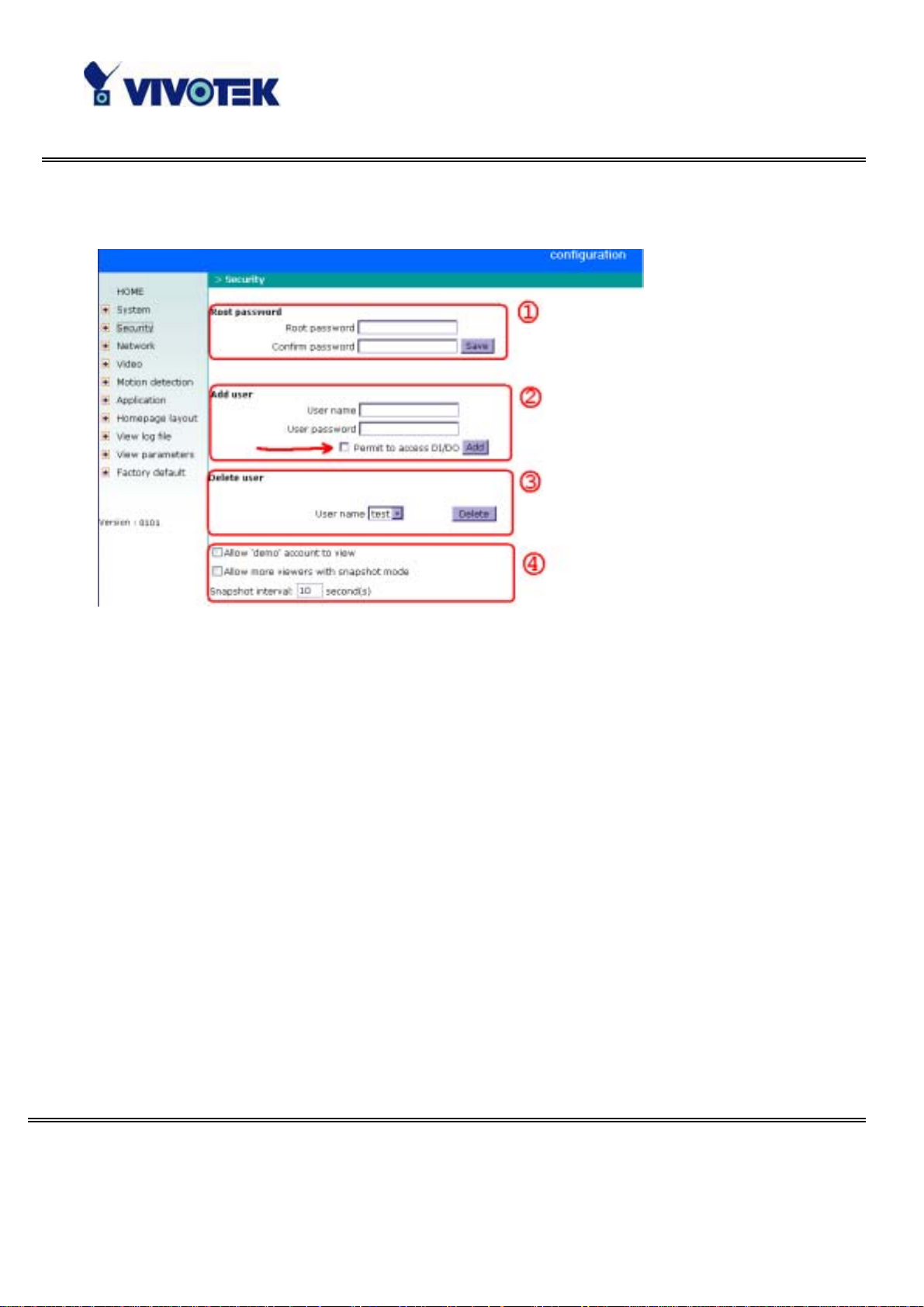
User group admi nist ration
“R oot pas sword ”, to chan g e th e ad mini strat o r’s passw ord , t yp e th e new p assw ord in
both text boxes identicall y . What is typed will be dis played as asteri sks f or the secu rity
purpose. After pre ssing
, the web brows er will ask adm inistrators for th e new
password for access.
“Ad d user ”, t ype th e n ew user's nam e and passwo rd and pr ess
to insert the new
entry. The new use r will display in the user name list for deletion. There are max imum
twenty user accounts. Each user can have privilege to “Permit to access DI/DO”.
“Delete user”, pull down the user list to find the user name and press
.
“Allow ‘demo’ account to vie w”, click to perm it who typing “demo ” a s user nam e
while authentication. No password is needed for demo account. Note that demo
account is restricted to v iew only.
“Allow more v iewers with snapshot mode” can let more viewers than limited
ac count to watch the video. However the video is a still imag e automatically r efreshed
by the interval defined below. This feature mu st be supp orted by java s cript capability
of web browsers.
“Sna pshot interval” defines the refresh ra te of the s till image in the hom epage seen
by overloaded viewers.
- 3 9 -
www.vivotek.com
T: 886-2-22404099
F: 886-2-22404097
Page 41

Network settings
Any cha nge made to this page will make the system re start to v alidate. Make sure
every fie ld is co rrectly typed be fore click ing on
"Reset IP address at next boot", the default status is checked to eliminate
incautious mistakes during installation. However it is very annoying to perform
software installation whenever Network C amera starts. Once the network settings,
especially the IP address, are correct, uncheck this option to use permanently. This
option can also be disable d using the Installer progra m . Once the optio n is disa bled,
Network Camera will skip installation at the next boot and the Install er pr ogr am will no
longer find the inst alled units. That implies that Network Cam era cann ot be acc ess ed if
no one remembers the IP address, except by restoring factory default settings.
However, with this option disabled Network Camera can automatically operate
normally a fter restarting in case of losing power.
.
General
“IP address ” , it is necess ary fo r network identification.
“Su bnet m a sk ”, it is us ed to d etermine if the d estina tion is in the s ame sub n et. The
def ault va lue is “255.255.255.0”.
“Default ro u t e r”, it is the gat ewa y used to f orward frames to destin ations in different
subnet. Invalid router setting will fail in transmission to destinations in different
subnet.
“Primary DNS”, pri ma ry do main n am e serv er wh o translates na mes t o I P addr ess es.
“Secondary DNS”, secondary domain name se rver to backup the primary one.
HTTP
“Http p ort ”, it can be ot h er t han defaul t port 80. On ce t he port is ch ang ed, user s must
be informed for successful conne ction. For instance, when the administrator changes
the HTTP po rt of Networ k Came ra who se I P add ress is 192.168.0.100 fr om 80 to 8080,
- 4 0 -
www.vivotek.com
T: 886-2-22404099
F: 886-2-22404097
Page 42

users must type in the web browser “http://192.168.0.100:8080” instead of
“http://192.168.0.100”.
Streaming
“Control cha nn e l port”, it can be o the r than default por t 5001 to cooperate with the
port opened by the firewall.
“Aud io channel po rt”, it can be o ther than d efault po rt 5002 to cooperate with the
port opened by the firewall.
“Video c hannel port”, it ca n be other than defa ult port 5003 to cooperate with the
port opened by the firewall.
“Improve audio quality in low bandwidth environment”, if Network Camera
works in versatile or low network bandwidth enviro nment, users can check this op tion
to improving audio quality by sa crificing some real-time synchro nization.
WLAN Configuration
“SSID” (Service Set Identifier), it is a name that identifies a wireless network. Access
Points a nd wireless clients attempting to connect to a specific WLAN (Wire le ss Local
A rea Netw or k ) m us t use the same S SID . T he def aul t se ttin g is default. No te: The
maximum leng th of S S ID i s 32 si ngl e-byt e ch ar act er s an d S S ID can ’t be an y of “ , < , >
and space character.
“Wireless mode”, clicking on the pull-down menu to select from the following
options:
“Infrastructure” – connecting the WLAN via an Access Point. (The default setting)
“Ad-Hoc” – connecting directly to a host equipped with a wireless adapter in a
peer-to-peer environment.
“Channel”, while in infrastructure mode, the channel is selected automatically to
match the channel setting for the selecte d Access Point. In Ad-Hoc mode, the channel
must be manually set to the same channel for each wireless adapter. The default
channel se tting depends on the installed region.
“TX rate”, to se le ct the ma x im um tr an sm is si on ra te o n the netw ork . 22M bps is the
defa ult setting.
- 4 1 -
www.vivotek.com
T: 886-2-22404099
F: 886-2-22404097
Page 43

g
s
“Preamble”, either “Long preamble” or “ Sho rt p reambl e” defines the length of the
CRC block (Cyclic Redundancy Check is a common technique for detecting data
tra ns m issio n e rro rs) f or com mun icati on be tween the A cces s Po int a nd the ro ami ng
wirel ess dev ice. Lo ng Pre amb le is the defau lt setti ng. Note : High network traffic areas
should use the shorter preamble type.
“Data encryption”, checking the box to enab le the data en cry ption . By defau lt it i s
disabled.
“A uth. Mode” , choosing one of the following modes, (Auto is the default se tting)
“Auto” – Will a u tomatically decide the authentica tion mode of the wire less clie nt.
“Sha re d” – allows communication only with other devices with identical WE P settings.
“Open” – communicates the k e y a cross the network.
“Key length”, selecting the key length among 64, 128 or 256 bits. 64bits is the
defa ult setting.
“Key format”, including h ex ade cima l or ASCII. “HEX” i s th e default settin g.
“HEX” dig its consist of the number s 0 ~9 an d the le tters A-F.
“ASCII” is a co de fo r representing English letters as numb ers f rom 0-127 exc ept “, <,
> and space characters that are reserved.
“N etwork Ke y” , enterin g a k ey i n ei t her hexa decimal o r A SCII f o rmat . When select i ng
different ke y le ng th, a cceptable input length is listed a s following:
64 bits key length: 10 Hex digits or 5 char acter s.
128 bites key leng th: 26 Hex digits or 13 cha rac ters.
256 bits key length: 58 Hex digits or 29 char acter s.
Note: Whe n 22(“), 3C(<) or 3E(>) are inp ut in ne twork key, th e key for mat can’t be
changed to ASCII forma t.
Some invalid settings may cause system failure to respond. Change the
confi
ur ation only if ne cess ary and consult with networ k supervi sor or expe ri en ced user
for corr ect settings. Once the system is lost contact, refer to Appendix A for reset and
restore procedures.
- 4 2 -
www.vivotek.com
T: 886-2-22404099
F: 886-2-22404097
Page 44

Ma il & FTP settings
SMTP
“SMTP(m ail) ser ve r 1” , th e domai n name or IP add ress of ext ernal email server.
“R eci pi ent email addres s 1”, the em ail addres s of reci pi ent s fo r sn a pshot s or log fil e.
Multiple rec ipients must be separated by s emicolon, ‘;’.
“SMTP(mail) server 2”, t he d omain nam e or IP addr ess of anot her email ser ve r on ce
the previous server is unreachable.
“Recipient email address 2”, the email address of recipients for the backup server.
“Return email address”, The return email address once the mails fail to send out.
FTP
“Local F TP s e rv e r port”, it can be other than default port 21. After changed, external
FTP client program must change the server port of connection accordingly.
“1st FTP server”, the domain name or IP address of external FTP server. The
following user settings must be correctly configure d for remote access.
“1s t FTP user name”, granted user name on the external FTP server.
“1st FTP password”, granted password on the external FTP serv er.
“1st FTP r emot e fold er”, granted folder on the external FTP serv er. The string must
co nf orm to the ex ter nal FT P ser ver. So me FT P s e rver ca nno t a cce pt p re c ed ing slas h
symbol before the path if no virtual path mapping. Refer to the instructions of external
FTP server for details. The folder priv ilege must be open fo r uploa d.
“Primary FT P passive mode” , if Network Camera is located inside the network
protected by firewall , data conn ection f or FTP ma y be prohibited. Passi ve mod e FTP can
bypass the rule and succeed to upload snapshots. If the passive mode is selected,
Network Camera can a utomatically attempt for ac tive mode if the external FTP serve r
does no t support passive mode .
“2nd F TP server”, the domain name or IP address of external FTP server.
“2nd FT P user name”, gra nted use r na m e on the backup FTP server.
- 4 3 -
www.vivotek.com
T: 886-2-22404099
F: 886-2-22404097
Page 45

“2nd FT P pass word”, granted passwor d o n the backup FTP serv er.
“2nd F T P remote fo lder” , granted folder on the backup FTP server.
“Secondary FTP passive mode”, passi ve mode set ti ng for t he backup F TP serv e r.
- 4 4 -
www.vivotek.com
T: 886-2-22404099
F: 886-2-22404097
Page 46

Vi deo codec parameters
“T ext on video ”, th e text will be d isplayed in the black bar above the video wind ow
with a times tamp. The tim estamp is c aptured from date and time of Network Camera
that is maintained by a built-in re al-time cloc k.
“Color”, select either one for color or monochrome vide o display.
"Size", there are three options for two video sizes. “Ha lf” has quarter size of
“Normal”. “Half x 2” has the same video size as “Normal” but has worse quality.
However it co nsume s less network ba nd width.
“Power line frequency (for fluorescent light)”, the fluorescent light will flash
according to the power line frequency that depends on local utility. Change the
frequ ency setting to eliminate uncomfortable flash image when the light source is onl y
fluoresc ent light.
There are three dependent parameters provided for video performance adjustment.
"Maximum frame rate", it limits the maximal refresh frame rate that can be
comb ined with the " Vide o quality co ntrol" to optimize the bandwidth u tilization and
vide o quality. I f users wa nt to f ix the ba ndwidth utilization r ega rdless of th e video
quali ty , cho ose "Fix bit rate" and sele ct t he desired b andwidt h. Th e vid eo qu ality ma y
be poor in or der to send m ax imal fram es within the limite d ba ndwidth when images
change drastically. Consequently to ensure the video detail (quantization rate)
re gardless of the network, it will utilize more ba n d wid th to send the max imal frames
when images change drastically.
"F lip " , vertically ro tate th e video.
"Mirror", horizontally rotate the video. Check both if Network Camera is installed
upside down.
“White ba l ance”, choose the suitable option for best color temperature.
, click this button to pop up another window to tune "Brightne ss",
“Contrast”, “Hue” and "Saturation" for video compensation. Each field has eleven
levels r anged from -5 to +5. The user m ay pr ess
t he i mag e i s O. K. , p r ess
to memorize the image settings. can be clicked to
to fine-tune the image. When
recall the origina l settings without changes.
- 4 5 -
www.vivotek.com
T: 886-2-22404099
F: 886-2-22404097
Page 47

- 4 6 -
www.vivotek.com
T: 886-2-22404099
F: 886-2-22404097
Page 48

Motion detection
“Enable mo tion detection”, ch eck th is option to tu rn on the mo tio n detection.
, cli ck on this butto n to add a new window. At mos t three w indows can exist at th e
same time. Use the mouse to drag the window frame to resize or the title bar to move.
C l ic ki ng on th e ‘x ’ a t the upp er r igh t co r ner o f th e w ind ow ca n del ete the wi ndow.
R emember to save to validate the chan ges .
, click on this button to save the related settings regarding to the window. A graphic
bar will rise or fa ll dep ending on the image v ariation. A green bar m eans the im age
va ria tion is und er monitor ing level a nd a red bar me ans the ima ge var iation is over
mon itoring level. When the bar goes red, th e detected window will also be outlined in
red. Whil e ba ck to th e homepage, the monitored window will hid e but t he red frame will
show when motion is dete cted.
"Window Name", the text will show at the top o f the win d ow.
“Sensitivity”, it sets the endurable difference between two sequential images.
“Percentage”, it decides the space ratio of motioned objects over the monitored
window. Higher s ensitiv ity and s mall perc entage will make motion easie r de te cted.
The f ol l ow in g f igure sho ws t he sc re en w hen
is clic ked. The monito ring window ha s
been o utlined in red and the graphic bar goes red since the goldfish is moving.
- 4 7 -
www.vivotek.com
T: 886-2-22404099
F: 886-2-22404097
Page 49

Application setup
Weekly schedule
“Sun” ~ “Sat”, select the weekdays that should perform the following operations.
“Snapshots begin at”, set the time to start operations. Setting begin time as same as
stop time will perform o p erations 24 ho u rs.
“Sna p s ho ts s to p at”, set the time to stop ope ration s.
E v ent o peration
“Delay second(s) before detecting next event”, set the time delay before
re s tarting to check the trigger cond ition whe n the current condition is trigge red.
“Take snapshots at second(s) after eve nt”, whe n a snapshot is taken upon the
con d ition is triggered, another snap shot will be ta ke n after the con f ig ured sec onds.
“Trigger condition”, there are four co ndi tio ns related to the digital input an d three
windows for motion detec tion. They can b e m ultip le selec ted. Select the a ppro pria te
digital inp ut condition according to the c har acte ristics of the external dev ice. “high”,
“low” indicate external voltage input or n ot for l evel trigger while “ rising” , “f alling” is for
edge trigger. There are three windows shown as the name for motion detection.
“undefined” will show inste ad of th e window title if motion det ection is not s etup yet. In
such cas e, cl ic kin g on t he “M ot ion det ect ion” i n t he not e can direct to t he conf igu rat ion
page o f m otion detection.
“T rig g e r act ion”, there are four options for two actions regarding to either condition.
The y can be m u ltiple selected. While choos ing trigger o utput alarm, the digital output
will shor t both pins to con nec t the circ uit of the atta ched ex ternal de vic e; o the rwis e
both pins will be ope n. While choosing to upload snap shots, the method can be either
email or FTP. The snapshot names will be “videopre.jpg”, videotrg.jpg”, and
“vi deopos.jpg” re sp ect ively for th e sn aps h ot s befor e e vent , rig ht up on event , and a ft er
e vent. Th e date a nd time s uffi x may be adde d ac cord in g to the o ptio n. Co nf ir m th e
externa l m ail or FTP ser ver settings in networ k co nfig uration.
- 4 8 -
www.vivotek.com
T: 886-2-22404099
F: 886-2-22404097
Page 50

“Res et o ut p ut”, check an d save this op tio n to rese t the external dev ice at the digital
output back to the orig inal state.
Sequen tial op eration
“Snapshot every second(s)”, Network Camera will send snapshots at the specified
interval to the external server according to the chosen method. Remember this
operation is still su b jec t to the weekly schedule .
“Send sna pshots by ema il”, any upload action specified in the options abo ve will u se
the method cho sen here. The captured snapshot named “video.jpg” will be att ached in
the email with subject “Periodic snapshots”.
“Send snapshots by FTP”, the capture d snapshots will upload to the external FTP
server with the file name depending on the next option. It ca n be used to refres h the
captured image stored in the external web server to build creative homepages.
“FTP pu t snapshot s w it h d ate an d t ime s uffix”, i f the suffi x is added, th e captur ed
date and time can be easily differentiated from the snapshot file name in either
sequential or event ope ration. For inst ance, “vi deo@ 20020102030405.jpg” means the
JPEG ima g e w as ca pt ured at 4 min ut es and 5 s econds aft e r 3 o’ cl ock, Januar y 1 st, A. D.
2002. If the suffix is omitt ed, the file na med “ video.jpg” on the external FTP s erver will
be refreshed at the specified interval.
- 4 9 -
www.vivotek.com
T: 886-2-22404099
F: 886-2-22404097
Page 51

Home page layo u t settings
“U s e the cu st o m i zed h omep age ” , check this opti on to use “use r.htm” uploaded by
administrators instead of the default one. Refer to the section “Administrator’s
ca p ability” for de tail usage. The following options re lated to the defa ult homepage will
not affect the “user.htm”.
“Logo graph”, the logo located at the upper left corner of homepage c an be hidden,
the d efaul t one that can be changed by a dmin istrators, or an y image on the Inter net
that can be located via URL. The default logo is s tor ed in memo r y and can be changed
by FTP . The ma ximal size i s 32000 byt es. Th ough the file name is fixed t o “log o.gif”, t he
image can be any file format as long as the web browser can read it. Refer to the
se ction “Administrator ’ s ca p ability” for ho w to chang e the defa u lt log o.
“Logo l ink”, when users click on the logo image, a new window will pop up to show
the homep age of the g ive n URL. Clear the URL will d isable the link func tion .
“Bac kg rou nd gr aph ”, the bac kground image ca n be hidden to show the background
colo r only, t he default one t h at can b e ch an ged by admi nistrat ors, or any im ag e on th e
Internet that can be located via URL. The default background image is stored in
memory and c an be chang ed by FTP. The ma ximal size is 131000 bytes. Though the file
name is fixe d to “wallppr.jpg”, it can be any file format as long as the web browser can
read it. Refer to the section “Administrator’s capability” for how to change the
back gr o und ima ge.
”Font color", pull down the list to select any colo r for the text in the homepage.
”Background color", pull down the list to select any color for the homepage
back gr ound. It can be see n when the background image is not displayed.
- 5 0 -
www.vivotek.com
T: 886-2-22404099
F: 886-2-22404097
Page 52

Viewing system log
Click the link on the configuration page to view the system log file. The content of the
file r ev ea ls us eful informa tion ab out configuration a nd co nnec tio n af te r the s ys te m
boots up.
Vie wing system parameters
Click th e li nk on t h e c onf igu rat ion pag e t o q ui c kl y view t he whol e system pa ramet er set .
The content is the same as C ONFIG.INI.
Re stor e factory default sett ings
C l ic k th e l ink o n the c o nfi gura tio n page to r es tore the fa c tory de fa ul t settin gs . Th is
me ans any changes made before will be lost and the sys tem will be r eset to the initial
status when shipped from the factory. A f te r c onfirmation, the system will restart and
requir e the install er progr am to setup the network.
- 5 1 -
www.vivotek.com
T: 886-2-22404099
F: 886-2-22404097
Page 53

y
s
e
Appendix
A. Troubleshooting
Status LED
Afte r the power has been turned on, Ne twork Camera will perform a self-diagnostic to
detect any hardware defects. The following table lists the LED patterns in general
con d itions. In c ase of any f atal e rro r, the LED will blink in anothe r patter n.
Condition LED color
During self-diagnostic after power on Blink in in te rcha n g ed green and red
Ethernet signal is lost Steady red till Ethernet is de te cted
Before network is s etup Steady green till I P ad d ress is confirmed
After network is setup Blink green every second
Any hardware failure Other patterns
Reset and r estore
There is a button hidden in the pinhole beside the
Ethernet socket. It is used to reset the system or
restore the factory default settings. Sometimes
re s etti ng the sy s tem can mak e the sys tem bac k to
nor mal s ta te . If the system still has pro ble ms after
reset, rest ore th e factory set ti ngs and i nst all agai n.
Restore the factor
RESET: Poke the wrench to click on the bu tton.
RESTORE: 1. Poke the wrench to press on the
button continuously.
def aults will lose any previou
settings. Reset or restore th
system after power on.
www.vivotek.com
T: 886-2-22404099
F: 886-2-22404097
2. Wait for s elf-diagnostic to run twice.
3. Withdraw the wrench as soon as the second
self-diagnostic starts.
- 5 2 -
Page 54

B. Frequently asked questions
Q What if I forge t my password?
A After the administrator's password is assigned, every access to Ne twork Camera
needs authentication. If you are one of the managed users, you have to ask the
administrator for the password. If you are the administrator , there is no w ay to recover
the root passwo rd ex cept for resto ring factory default. Refe r to Appendix A fo r the
procedures.
Q Why can I not w atch video f rom Networ k Camera after it is au thenti cated ?
A The r e are many possible sce na r io s r egarding this problem,
1. If you have just installed Network Camera and a re unable to watch the vide o, check
if the heartbeat LED is blinking or the lens cap is removed. If the heartbeat LED is dim,
perform the software installation again .
2. If Ne two rk C amera is well installed and you are accessing Network Camera f or the
first time using Intern et Explorer , adjust the securit y level of Internet Explorer to allow
installation of p lug -ins.
3. If the problem still exists after adjus ting, and the message over the image window
is showing "connecting", the network traffic may be too crowded.
Q What is the plug-in fo r ?
A The plug-i n p ro vided by N etwor k Came ra is us ed t o di spla y mot ion pictur es and au di o
in Internet Explorer. If your system does not a llow insta llation of any plug-in softwar e,
the security le vel of t he web brows er may ne ed to be lowered. It is rec ommende d t hat
you consult your network supervisors in your office regarding adjustment of the
se curity lev el. S oftware installation may be r egulated in some off ices .
Q Why is the timestamp different from the system time of my PC or notebook?
A The ti mes tamp is based on the sys tem time o f Network Camera. It is main tained by
a rea l-time clock inside and ca n be automa tically synchronized with the time server if
Network Camera is connected to the Intern et and the fun cti on is en abled . Differences
of several hours may result from the time zone setting.
- 5 3 -
www.vivotek.com
T: 886-2-22404099
F: 886-2-22404097
Page 55

Q Can I install it on ceiling?
A Yes. There are flip and mirror options in video configuration page to correct the
ima g es for upside d own installation.
Q The image is not clear enough.
A Rotate the len s to adjust the fo cu s af ter Network Camera i s i ns tal le d in the proper
position. The image settings and white balance can be fine tuned to achieve the best
visual effect. Also notice the power line frequency must match the local utility to
sy nc hronize the flor escent lights to eliminate the unco mfortab le flas hing.
Q Why does the image not refresh regularly?
A Some anti- virus progr ams will provide function s to filter the recei ved w eb content. It
will take time to perform th e da ta exam ination a nd a ffec t the stre aming application
such as N etw or k Ca me ra. H owe ve r it only affe ct s t he H TP mod e of N etw or k Camer a. If
the network allows the HTTP mode only, disable the web filtering function of the
anti-virus program temporarily. During the period, users should take the risk of
malicious netwo rk activity.
Q I hav e opene d motion detection windows but it cannot work.
A If the motion detection windows are setup and n ames are given, check if the function
is checked at the first line. While it is enabled, adjust the sensitivity and percentage to
monitor the level indica tor if the thresh ol d is appro priate.
Q I cannot hear any sound while watching.
A If there is "V_ONLY" shown above the image, click on connection type to uncheck
"Disable aud io". If there is "V" shown instead of "AV", the sound card in your PC may
not properly inst all ed. If "AV" is shown, check th e audio sou rce of Net work Camera.
Q How many us ers a re allo wed to watch N etwork Camera a t the s ame time?
A Too man y users requesting the real-time multimedia cont ent will digest the network .
To achieve the best effect, Network Camera is designed to accommodate maximum ten
user s to watc h a nd liste n to Netw ork Camera at the same ti me. It i s rec ommended to
- 5 4 -
www.vivotek.com
T: 886-2-22404099
F: 886-2-22404097
Page 56

build anoth er web server to host a larg e quan tity of users by retrieving contents from
Network Camera periodically.
Q How fast is the video rate of Network Camera?
A The MPEG4 codec engine can process 30 frames per second internally. However the
total performa nc e is su bj ect to m any coeffi ci ents as f ol lo ws:
1. Network throughput,
2. Bandwidth shar e,
3. Number of users,
4. The complicated objects and movement in view,
5. The lev el of your PC or noteboo k which is re sponsible f or displaying im age s.
I n general, the tra nsfer rate in a ge neral local netwo rk envi ronment ca n achieve ove r
200 kilobyt es p er s econd and a ppro ximately 10 to 20 pi ctures of a normal environment
per second.
Q How can I keep Network Camera as private as possible?
A Network Camera is designed for surveillance purposes and has many flexible
in ter fa ces . The user a uthe nti ca tio n a nd spe cia l co nfirm ati on in insta ll ati on ca n kee p
Network Camera from unauthorized access. You may also change the HTTP port to
non-public number. T he demo account is good to separate guests from normal users
and thus you c an easily blo ck gu ests anytim e. You can check the syst em log to e xami ne
any abnormal activities and trace the origins.
Q Why can I not access Network Camera when I setup some options in the appli cation ?
A Since Network C amera is a "network camera", any incorrect network settings will
make it unre a cha ble. Once the system is missed due to wrong configuration, re store
the factory default settings following procedures in Appendix A.
- 5 5 -
www.vivotek.com
T: 886-2-22404099
F: 886-2-22404097
Page 57

C. URL commands of Network Camera
For some customers who a lre a dy have the ir own web site or web control application,
Network Camera can be easily integrated through c onvenient URLs. This section lists
th e comm ands in URL for mat co rre spondi ng t o t he b asic fu nct ions of N etw or k Ca me ra.
Capture update Snapshot of JPEG image
/cgi-bin/video.jpg
Network Camera will r eturn the m ost up-to-date snapshot in JPEG f orm at.
Query status of the digital input
/cgi-bin/g etdi.cgi
Network Camera will return the status of d ig ita l inp u t.
Drive the digital ou tpu t
/cgi-bin/setdo.cgi?do=<state>
, wh ere st at e is H , L. H mean s NC conn ect ed wit h COM M ON and L m eans N O conne ct ed
with COMMON.
For instance, typing http://192.168.0.201/cgi-bin/setdo.cgi?do=h
the web bro wser will comman d Network C ame ra , with IP address of 192.168.0.201,
set digital ou tput to conn ect to NC with COMMO N .
in address bar of
Restore f actory defau lt settings
/setup/restore.cgi
Network Camera will automatically restart after restoring factory default
- 5 6 -
www.vivotek.com
T: 886-2-22404099
F: 886-2-22404097
Page 58

configurations.
Restart sy stem
/setup/reset.cgi
R estar t N etwork Ca mera without warning.
- 5 7 -
www.vivotek.com
T: 886-2-22404099
F: 886-2-22404097
Page 59

Page URL
The configuration page has a frame layout including an option list frame and an option
page frame . Referenc ed URLs, except for the configuration page , direct users to the
option page f rame only . Some pag es, like image qu alit y sett ing and pr eset s ett ing, are
opened in new windows for preview.
These URLs can be a ccessed only by administrators.
Homepage name Reference d UR L
conn ection ty p e pa g e /clie nt.html
config uration pa g e /setup/config.html
system option /setup/syste m.html
security option /setup/security.html
network option /setup/network.html
video option /setup/vide o.html
motion detection /se tup/motion.html
ima g e quality option /s etup/ima ge.html
app lication o ption /se tup/app.html
homepage layout option /setup/layout.html
sy stem log /se tup/logfile .html
sy stem parameters /se tup/parafile.h tml
set factory d efault /setup/fa ctor y. html
System resour ce URL
The re are some imag es used on the home page when the homepage layout is in image
mode. Administrators m ay use the f ollowing lin ks to sh ow the im ages saved in Network
Camera on another page.
Re sourc e nam e Re f ere nced UR L
sy stem logo image /pic/lo go.gif
back gr o und ima ge /pic/wallppr.jpg
- 5 8 -
www.vivotek.com
T: 886-2-22404099
F: 886-2-22404097
Page 60

y
y
General format of co mmand URL
Every configuration can be set through URL with POST method by admini stra tors on ly.
<general format>
URL[?[name=value][&name=value]……]
<method>
POST
<authoriz ed user>
root
System configuration URL
URL: /setup/system.cgi
NAME VALUE DESCRIPTION
host <text string shorter than 15
characters>
ye s turn off front LED Ledoff
no turn off front LED
method
keep keep date and time unchanged
auto use NTP server to synchronize
manu directly adjust date and time
date <yyyy/mm/dd>
time <hh:mm:ss> hour, minute and second separated
ntp <dom ain name or IP address> NTP s erver
system name
ear, month and date separated b
slash
by colo n
zone -12 ~ 12 time zo ne, 8 means GMT +8:00
- 5 9 -
www.vivotek.com
T: 886-2-22404099
F: 886-2-22404097
Page 61

Security configuration URL
URL: /setup/security.cgi
NAME VALUE DESCRIPTION
rootpass <text string shorter than 15
change root password
characters>
username<text string shorter than 15
add new user
characters>
userpass <text string shorter than 15
new user's password
characters>
deluser <text string shorter than 15
existing user name
characters>
ac tion <b lank> validate d emo use rs with “open”
yes grant for demo account open
no prohibit for de mo a c count
yes permission for DID O a cce ss dido
no prohibit for D IDO access
- 6 0 -
www.vivotek.com
T: 886-2-22404099
F: 886-2-22404097
Page 62

Network configuration URL
URL: /setup/network.cgi
NAME VALUE DESCRIPTION
yes enable installation at next boot reset
no dis able installation at ne xt boo t
ip <IP addr ess> Network Camera's I P addre s s
subnet <IP address> subnet mask
router <IP addr ess> default gateway
dns1 <IP addr ess> primary DNS se rver
dns2 <IP a ddress> secondary DNS serve r
http <number le ss than 65535> HTTP por t
cpo rt <num b er less than 65535> control Channel p ort
vport <number les s than 65535> vid eo Channel port
aport <number le ss than 65535> a ud io Channel port
ye s optimal fo r th e low bandwid th band
no keep the original way
ssid <text string shorter than 33
WLAN SSID
characters>
inf WLAN infrastructure mode wl
ad WLAN Ad Hoc mode
chan
1 ~ 11 c hannel in USA
1 ~ 11 cha nnel in Canada
1 ~ 13 cha nnel in Euro p e
10, 11 chan nel in Sp ain
10 ~ 13 channe l in France
1 ~ 14 cha nn el in Jap an (all)
tx
1 1 Mbps transmission rate
2 2 Mbps transmission rate
3 5.5 Mbps transm ission rate
4 11 Mbps transm ission rate
- 6 1 -
www.vivotek.com
T: 886-2-22404099
F: 886-2-22404097
Page 63

5 22 Mbps transm ission rate
l long preamble prea m b
s short preamble
yes enable data encryption encr
no disable data enc r yption
auth
auto auto authentication
shared shared-key authentication
open open-key authentication
klen
1 64 bits k ey length
2 128 bits key length
3 256 bits key length
h hexadecimal format of key kform
a ASCII format of key
dkey 1 ~ 4 o ne of four keys
netkey1 hexadecim al string (00 ~ FF) network k ey 1
netkey2 hexadecim al string (00 ~ FF) network k ey 2
netkey3 hexadecim al string (00 ~ FF) network k ey 3
netkey4 hexadecim al string (00 ~ FF) network k ey 4
*Hexadecimal string means the string is composed of two-digit ASCII code indicating
the hexadecim al value. For example, if the network key is “abcde fg” in ASCII format,
the hexad ecim al string will be “61626364656667”.
- 6 2 -
www.vivotek.com
T: 886-2-22404099
F: 886-2-22404097
Page 64

Mail& FTP configuration U RL
URL: /setup/mailftp.cgi
NAME VALUE DESCRIPTION
smtp1 <domain name or IP a ddress> primary SMTP server
mailto1 <string shorter than 80
mail recipient addre s s
characters>
smtp2 <domain name or IP a ddress> secondary SMTP server
mailto2 <text string shorter than 80
mail recipient addre s s
characters>
returnemail<text string shorter than 80
return email address
characters>
ftpp <number less than 65535> FTP p ort
ftp1 <domain name or IP address > primary FTP ser ver
ftpuser1 <text string shorter than 15
user na m e for primary FTP se rver
characters>
ftppass1 <text string shorter than 15
passwor d fo r primary FTP server
characters>
ftpfolder1 <text string shorter than 40
upload fo lder in p rima ry FTP server
characters>
ftp2 <domain name or IP address> se condary FTP server
ftpuser2 <text string shorter than 15
user name for secondary FTP server
characters>
ftppass2 <text string shorter than 15
password for secondary FTP se rv e r
characters>
ftpfolder2 <text string shorter than 40
upload folder in secondary FTP ser ver
characters>
- 6 3 -
www.vivotek.com
T: 886-2-22404099
F: 886-2-22404097
Page 65

Video config uration URL
URL: /setup/video.cgi
NAME VALUE DESCRIPTION
text <text string shorter than 15
characters>
size
1 half
2 ha lf x 2
3 normal
B/W monochrome color
<other than B /W> col or
fixb fix bit rate quality
<other than fi xb> fi x quantiza tio n
quan
1 lowest qua lity of vide o
2 lower q uality o f video
3 normal quality of video
4 higher quality of video
5 highest quality o f video
bitrate
64000 set bit rate to 64K bps
128000 se t bit ra te to 128K bps
enclosed caption
256000 se t bit ra te to 256K bps
384000 se t bit ra te to 384K bps
512000 se t bit ra te to 512K bps
768000 se t bit ra te to 768K bps
1000000 set bit rate to 1000K b ps
1200000 set bit rate to 1200K b ps
frame
1 set maximum frame ra te to 1 fps
2 set maximum frame ra te to 2 fps
3 set maximum frame ra te to 3 fps
5 set maximum frame ra te to 5 fps
10 set maximum frame rate to 10 fps
- 6 4 -
www.vivotek.com
T: 886-2-22404099
F: 886-2-22404097
Page 66

wb
15 set maximum frame rate to 15 fps
20 set maximum frame rate to 20 fps
25 set maximum frame rate to 25 fps
30 set maximum frame rate to 30 fps
50Hz synchronize with 50Hz utility mode
60Hz synchronize with 60Hz utility
1 a uto white bala n ce
2 fixed indoor(2800K)
3 fixed f luore scent 1(3600K )
4 fixed f luore scent 2(4000K )
5 fixed outdoor(6000K)
yes flip image flip
no normal image
yes mirror image mirror
no normal image
- 6 5 -
www.vivotek.com
T: 886-2-22404099
F: 886-2-22404097
Page 67

Ima ge qua lity configura t ion URL
URL: /setup/image.cgi
NAME VALUE DESCRIPTION
brightness<-5 ~ 5> adjust brightness of image
contrast <-5 ~ 5> adjust contrast of image
hue <-5 ~ 5> adjust hue of im age
saturation <-5 ~ 5> adjust satura tion of image
preview <not re q uired > not save the p arame te rs
re store <not required> recall the origina l settings
save <not required> sa ve the parame ters
- 6 6 -
www.vivotek.com
T: 886-2-22404099
F: 886-2-22404097
Page 68

Application c onfiguration U RL
URL: /setup/app.cgi
NAME VALUE DESCRIPTION
emode <not required> event mode application
smode <not require d> sequential mode application
ma il upload snap shots by email smethod
ftp uplo ad snapshots by FTP
suffix <not required> FTP file with date and time suffix
delay <integer> seconds delay to detect next event
int er <int eger> seconds del ay to capt ure post- event
dihigh < no t require d > set DI high as trigger c o ndition
dilow < not required > set D I low as trigger condition
dirise < not required > set DI rising as trigger condition
difa ll < not requir ed > set DI falling a s trigger condition
moti on1 < n ot required > set moti on win dow1 as trigger
condition
moti on2 < n ot required > set moti on win dow2 as trigger
condition
moti on3 < n ot required > set moti on win dow3 as trigger
condition
ioalarm < not required > trigger DO when DI condition
matched
mdalarm < no t required > tri gg er DO when mo tio n detected
ioupload < not required > upload snapshot when DI condition
matched
mdupload < not required > upload snapshot when motion
detected
sinter <integer> seconds interval for seque ntial mode
sbegin <hh:mm:ss> time to start sequential mode
send <hh:mm:ss> time to stop sequential mode
- 6 7 -
www.vivotek.com
T: 886-2-22404099
F: 886-2-22404097
Page 69

Homepage layout configuration URL
URL: /setup/layout.cgi
NAME VALUE DESCRIPTION
cuslogo
blank hide logo
def use default logo
url use image from URL
logourl <text string shorter than 80
URL of ima g e fo r logo
characters>
linkurl <text string shorter than 80
URL to link when clicking on logo
characters>
cusback
blank hide backgro und image
def use default background
url use image from URL
backurl <text string shorter than 80
URL of image fo r background
characters>
fcolor <0 ~ 15> co lor inde x for font
bcolor <0 ~ 15> color index for backgro und
- 6 8 -
www.vivotek.com
T: 886-2-22404099
F: 886-2-22404097
Page 70

D. Technical specifications
- Networ kin g
Protocol
TCP/ IP, HTTP, SMTP, FTP, Telnet, NTP, DNS and
DHC P
Ethernet
10BaseT o r 100BaseT Fa st Ethern et
WLAN
2.4GHz 802.11b+ DSSS CSMA/ CA
22/11/5.5/2/1M bps
Covera ge : 100M/ 22Mbps, 150M/11Mbps,
250M/5.5Mbps, 300M/2Mbps, 350M/1Mbps
- Vi deo
Algorithm supported
MPEG4(short header mode)
Features
Adjustable image size, quality and bit-rate
Timestamp an d t ext overlay
Intelligent motion detection windows
Resolu tion
Up to 30 fr ames at 160x120
Up to 30 fr ames at 320x240
- Camera specificat io n
1/3 inch color CMOS sensor
640x480
2.5Lux/F1.4
AGC/AWB
Electronic shutter: 1/60 ~ 1/15000 second
- Lens
Standard CS mount type lens, 6mm, F1.8
- Audio
24Kbps
- Microphone
Omni -directional, SNR > 60dB
Freque ncy 50-16000Hz
- 6 9 -
www.vivotek.com
T: 886-2-22404099
F: 886-2-22404097
- General I/O
1 opto-isolated sensor input(max. 12VDC
50mA )
1 r ela y out put(m a x. 24VDC 1A, 125 VA C 0. 5A)
- Security
Administr ator and user group pr otected
Password authentication
- LED indicator
Dual color system status indicat or
- Powe r
Input 100-240VAC, 50/60Hz, 0.4A,
Outp ut 12VDC 1.5A
Consumption near 8.4W
- Operat ing Environ ment
T emperature 0-50°C(32-122°F)
Hum id ity 95% R H
- Weight
NET . 315g
- Dimension
143.5mm(L)x88.9mm(W)x57.2mm(H)
- Viewing system requirement
Protocol
Standard Internet TCP/IP suite
Operating system
Microsoft Windows
Browser
Inter net Explorer 5.x or above
Page 71

s
Ele ct romagnetic Compatibility (E MC)
USA - Th is equipment ha s been tested and found to comp ly with th e limits for a Class B digita l d evice,
pursuan t to Part 15 o f the FCC Rules. These limits are d esigned to prov id e reasonab le prote c tio n aga inst
harm ful inte rference in a re sid entia l installatio n. This e q u ip men t g enera tes, uses an d can radiate radio
freq u ency ene rgy and , if not installe d and used in accorda nce with the instruction s, may cause ha rm ful
interf erence to radio comm u n ications. H owever, there is no g u arantee tha t int erfere n ce will not occur in
a partial insta llation. If this e quipm ent do es cau se harm ful inte rf erence to rad io or television rece p t io n ,
which can be determined by turning the equipment off and on, the user is encouraged to try to correct the
interference by one or more of the following measures:
-- Reo rie n t or reloca te the re ceivin g anten n a.
-- Increase the seperation between the equipment and receiver.
-- Connect the equipment into an outlet on a circuit different from that to which the receiver is connected.
-- Co nsult the de a le r or an e x p e rienced radio/TV technician for help.
Shielded inte rf ace cable s must be u sed in o rder to comply with emission limits.
Europe - This d ig ital eq uip men t fulfills th e requ ire ment for radiated emission according to limit
B of EN55022/1998, and the requirem e nt f or immunity according to EN50082-1/ 1992.
Liability
Vivotek Inc. cannot be held responsible for any technical o r typographical errors and reserves the right to
ma ke change s to the prod u ct a n d manuals w ithout prior notice . Viv o tek Inc. makes no warranty of a n y
kind with regard to the material contained within this document, including, but not limited to, the implied
warranties of mercha nt ability and f itn ess fo r a p articular purpo se.
Vivotek Inc.
Web s ite: www.vivotek.c om
Email: technical@vivotek.com
sales@vivotek.com
Rev. 2.01 Made in Taiwan. ©Copyright 2002. All right
 Loading...