

Page 1
VIVOTEK Mounting Accessories
Installation
II
AM-713 Junction Box
Installation Guide
Revison History:
Rev. 1.1: Added info. for EPoC application.
Rev. 1.2: Added surge protection connection.
Compatible cameras/brackets
FD836B-HTV, FD836B-EHTV, FD836B-HVF2, FD836B-EHVF2, FD8382-TV, FD8382-ETV, FD8382-VF2, FD8382-EVF2, FD9381-HTV,
FD9381-EHTV, FD9371-HTV, FD9371-EHTV
Mounting Dimensions
Rev. 1.0: Initial release
Compatible VIVOTEK Cameras
I
51.00 51.00
5.20
Part no.: 625031302G
Accessory Ordering part no.: 100138700G, AM-713_V01
EPoC junction box part no.: 100201400G
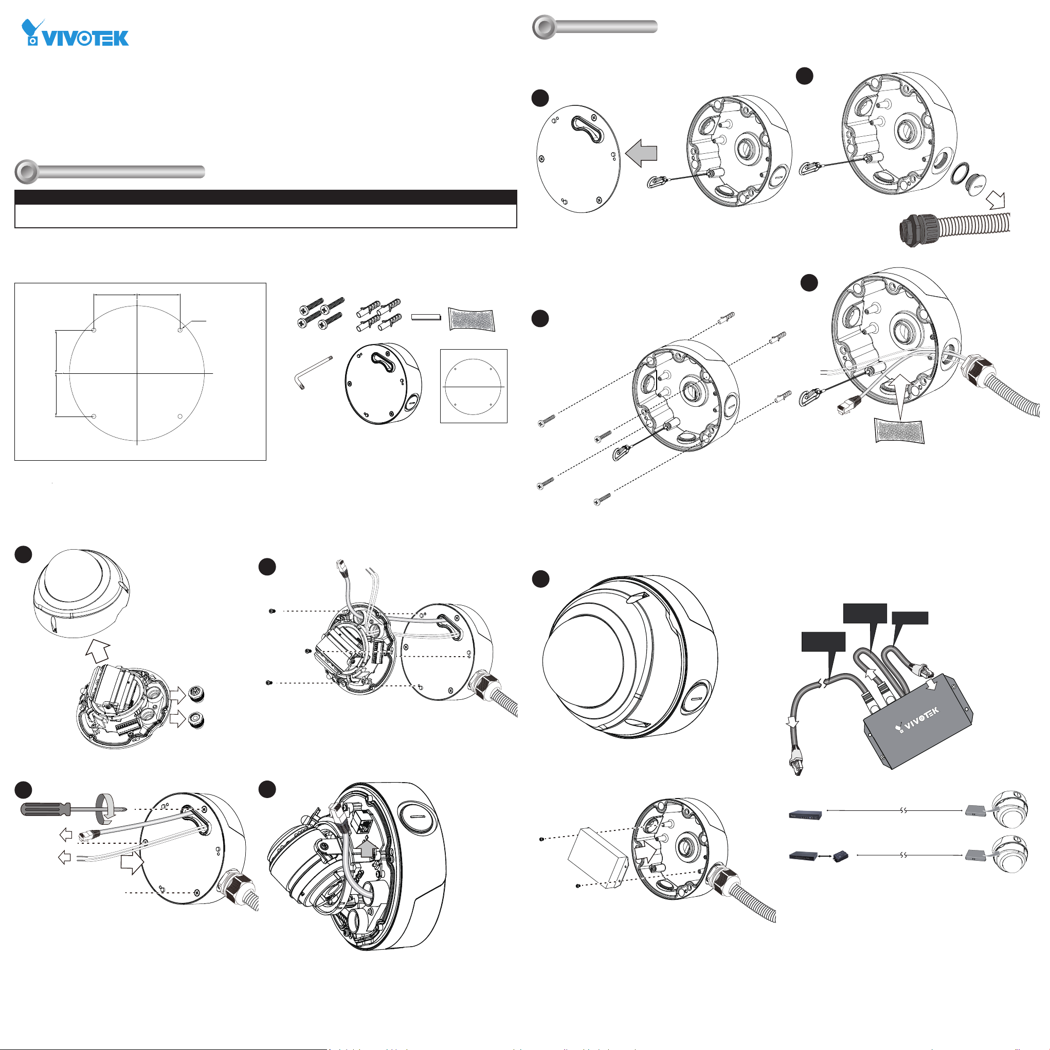
Package Contents
Remove the top cover and unhook the tether wire.
NOTE: If you have a POE extender or EPoC device, install them now.
Refer to the later section for details.
1
Attach the included alignment sticker to a preferred position. Drill holes
on the wall and install the junction box. If space behind the wall allows,
you may also pass cables through the wall.
2
A 3/4" conduit is required for routing the cables with waterproof
connection.
3
Install the cable gland and pass cables through it.
4
51.0051.00
Remove the dome cover and waterproof connectors.
5
Pass cables through the routing holes and install the camera to box by
driving screws.
7
Open a live view console and adjust the shooting direction. Refer to the
camera's QIG for more information.
Secure the camera top cover.
Connect the PoE IN and PoE OUT cables.
9
Put tags on the cables marking their intended use.
Attach a desiccant bag to the inside of the box. Note that the
installation should be completed within 30 minutes so that
desiccant remains effective.
PoE OUT
PoE OUT
to camera
to another conduit
box
PoE IN
Pass cables through the center hole on the top cover. Secure the
top cover by driving screws.
6
Connect cables to the Ethernet port and terminal block.
8
Optional Installation-1
You can also install a PoE extender (AP-FXC-0200) to the box.
AW-FCT-050A-250
PoE Switch
Indoor EPoC
RG6 1.2km
RG6 1.2km
AP-FEX-0106-T
EPoC Tx Module
AP-FEX-0106-T
EPoC Tx Module
Page 2
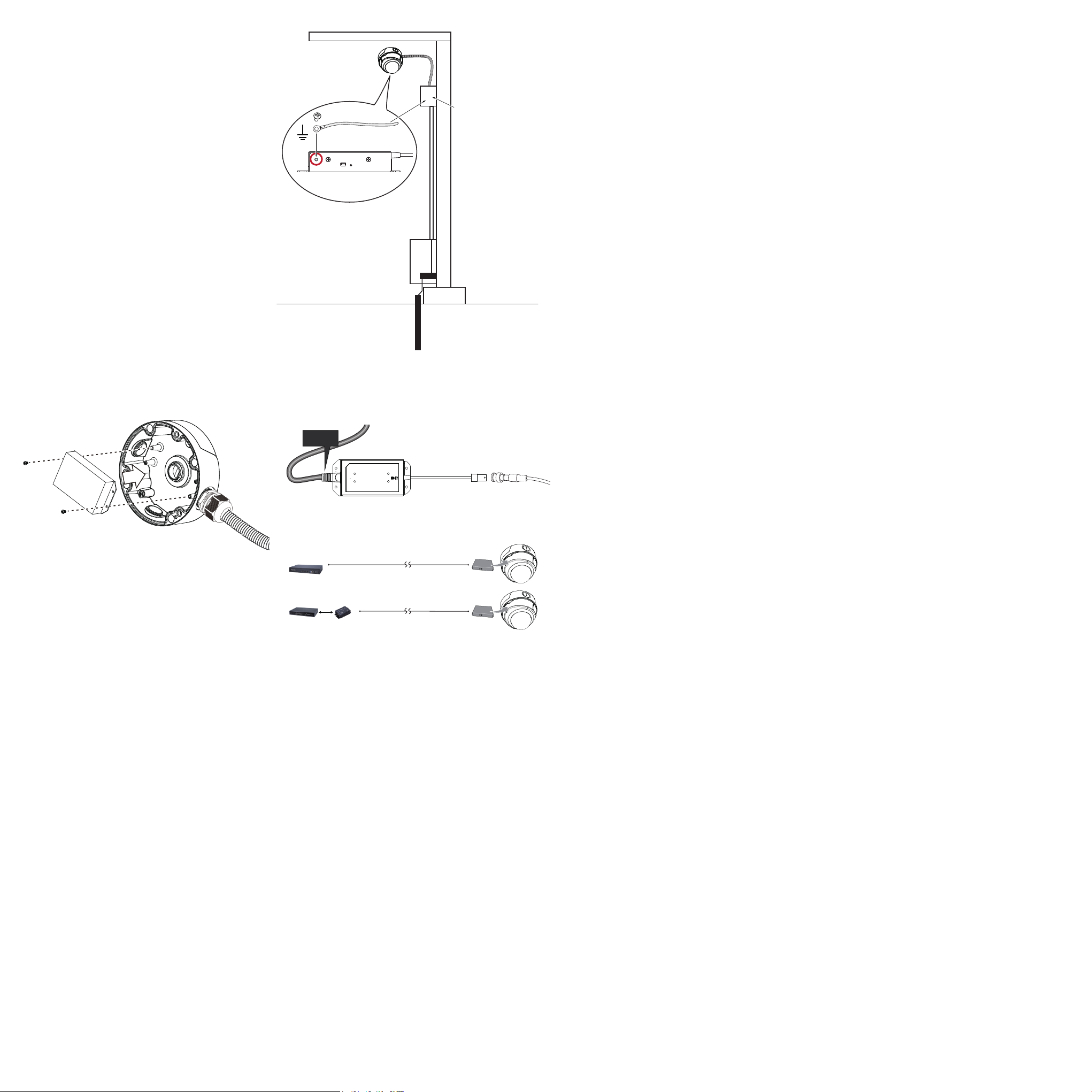
Surge Protection
Connect a ground wire to a surge protection device using the
grounding hole on the EPoC Tx module so that the device is
protected.
Surge protection
≧20AWG
AP-FEX-0106-T
Equipment enclosure
Equipment grounding
Optional Installation-2
You can also install an EPoC Tx module (AP-FEX-0106-T) to the
box.
Connect the PoE OUT cable to the camera.
Connect an RG6 coaxial cable to the BNC connector on the module.
PoE OUT
to camera
AW-FCT-050A-250
PoE Switch
Indoor EPoC
RG6 1.2km
RG6 1.2km
AP-FEX-0106-T
EPoC Tx Module
AP-FEX-0106-T
EPoC Tx Module
 Loading...