

Page 1

ACTIVE SPEAKER SYSTEM 5.1
MODEL VT-4029 SR
INSTRUCTION MANUAL
3
7
11
15
19
www.vitek-aus.com
4029.indd 14029.indd 1 07.04.2006 15:52:5807.04.2006 15:52:58
Page 2

4029.indd 24029.indd 2 07.04.2006 15:53:2907.04.2006 15:53:29
Page 3

ENGLISH
SOUND ACOUSTICAL SYSTEM VT-4029
SYSTEM BLOCK (FRONT VIEW)
1. Display
2. Volume regulator knob
3. SPEAKER SETUP button
4. Speaker indicators (FRONT L, CENTER, FRONT R, REAR L,
SUBWOOFER, REAR R)
5. SURROUND MODE indicators (MOVIE, CLASSIC, PANORAMA)
6. CENTER MODE indicators (PHANTOM, NORMAL, WIDE)
7. SURROUND MODE indicators (PROLOGIC, 3 STEREO, STEREO)
8. TEST TONE button
9. INPUT button
10. STANDBY button
11. POWER ON/OFF button
12. STANDBY indicator
1. STANDBY button
2. INPUT button
3. VOLUME UP/DOWN button
4. SURROUND MODE button (PROLOGIC, 3 STEREO, STEREO)
5. TEST TONE button
6. PRESET EQUALIZER button (FLAT, CLASSIC, ROCK, POP, JAZZ)
7. CENTER MODE button (PHANTOM, NORMAL, WIDE)
8. SPEAKER SETUP button (FRONT L, CENTER, FRONT R, REAR L,
SUBWOOFER, REAR R)
9. SURROUND DELAY button
10. CENTER DELAY button
11. EFFECT button (MOVIE, CLASSICAL, PANORAMA)
12. MUTE button
The remote control unit operates on two “AA” or “R6” batteries.
VENTILATION
The device should be well ventilated in order to avoid overheating.
Do not enclose the device’s housing and do not install it in places with limited ventilation. Make sure that there is enough free space on both sides
of the device and that there is at least 20 cm of free space above.
TURNING ON THE SYSTEM
Switch the POWER ON/OFF (11) button to the “ON” position; the device
will enter standby mode. Press the STANDBY (10) standby button to turn
on the system.
SPEAKER PLACEMENT
This acoustical system has six sound channels. The subwoofer is located
in the device itself.
Place the speakers as illustrated below.
a. Front speakers
b. Main unit with subwoofer
c. Center speaker
d. Rear speakers
e. Location of viewer/listener
REMOTE CONTROL UNIT
Place the center speaker between the two front speakers. The center
speaker can be placed on the television, as it is equipped with a protective magnetic shielding.
The rear speakers do not have magnetic field shielding.
Do not place them near a television or computer display, as this can damage the image projection.
Do not place cassette tapes on the speakers.
If you place the main unit too close to your television, it may cause image
distortion.
All connections should be made with the main power off.
3
4029.indd 34029.indd 3 07.04.2006 15:53:2907.04.2006 15:53:29
Page 4

ENGLISH
CONNECTING THE SPEAKERS
Connect the speaker cables to the corresponding jacks on the rear panel
of the amplifier, according to the indicated color code and polarity. Press
down on the corresponding clamp. Without releasing the clamp, insert
the end of the corresponding wire into the terminal (round hole), and then
release the clamp. The wire is now firmly attached. Connect the center
speaker remote control transceiver cable to the transceiver input jack located on the rear panel of the device.
All connections should be made with the main power off.
POWER
1. Insert the power plug into an electrical outlet.
2. Switch the POWER ON/OFF (11) button to the “ON” position. The red
STANDBY (12) indicator will light on the front panel of the device.
3. Press the STANDBY (12) button on the main unit or (1) on the remote
control unit to turn on the system. The display on the front panel of the
device will show the volume level.
4. In order to completely turn the system off, switch the POWER ON/OFF
button (11) to the OFF position.
CONNECTING TO A SOURCE SIGNAL
In order to playback 5.1 channel sound, use RCA cables or a digital cable
to connect the audio output you’re your DVD player to the corresponding
audio input on the system.
Use an RCA cable to connect the audio output from a DVD or CD player to
the corresponding left (white) and right (red) CD (AUX 1) or AUX 2 input.
4
4029.indd 44029.indd 4 07.04.2006 15:53:2907.04.2006 15:53:29
Page 5

ENGLISH
OPERATING THE DEVICE
Choose the signal source and sound format.
1. Digital source
In order to use a digital input signal, press the INPUT (9) (2) button and
choose the OP or (Optical) or CO (Coaxial) input.
During MP3 or CD playback on a DVD player, the sound will be reproduced in the two-channel PCM format.
2. AUX1 / AUX2 source
To reproduce sound from a CD or DVD player (when connected using an
RCA cable), press the INPUT button and choose the AU (AUX2) or CD
(AUX1) source.
Note:
This system has built-in Dolby Digital (AC3)/Dolby Prologic.
SOUND EFFECTS:
In order to choose one of these sound effects (Dolby Pro Logic, 3 STEREO
or STEREO), press the SURROUND MODE (7) (4) button.
In Dolby Pro Logic mode you can choose the center speaker’s sound
mode.
Normal:
(all six speakers and their indicator are active).
This mode should be used when a compact speaker, which cannot produce bass sounds lower than 100 Hertz, is used as the center speaker.
Low-frequency signals will be distributed to the front left and right speakers.
Wide:
(all six speakers and their indicator are active).
This mode should be used if the center speaker is the same size as the
front left and right speakers and can reproduce sound frequencies lower
then 100 Hertz.
Phantom:
(five speaker indicators are active, the center speaker is turned off).
This mode should be chosen if the center speaker is no being used.
The center channel will be split between the front left and right speakers.
If the 3 Stereo mode is chosen, the front left and front right speakers, the
subwoofer, and the corresponding indicators should be active.
In Stereo mode, the front left and front right speakers are active, as well
as the subwoofer and the corresponding indicators.
The Dolby Pro Logic mode excludes the use of the NORMAL, WIDE, and
PHANTOM center channel modes.
Each of these modes stipulates a set of parameters to be used for the
center channel (echo).
Each of these modes has its own signal delay (or echo).
- NORMAL provides true Dolby Pro Logic sound.
- WIDE allows you to achieve different acoustical divisions of the center
channel.
- PHANTOM turns off the center channel.
- The front right and left channels can imitate the sound of the center
channel.
- The center speaker is not used.
Pressing the EFFECT button on the remote control unit allows you to
choose from the following sound effects: Movie, Classical, Panorama or
2.1.
VOLUME LEVEL
1. In order to change the volume level, use the volume regulator knob (2)
located on the front panel of the device or the VOLUME UP/DOWN (2)
buttons located on the remote control unit. The volume level will be
shown on the display screen (0–22).
2. The volume of each of the six speakers can be set independently by
pressing the SPEAKER SETUP button (3). After the indicator for the
corresponding speaker begins to blink, set the desired volume level
using the volume regulator knob (1) within the bandwidth of +/-6 dB.
3. In order to verify that all five speakers and the subwoofer are correctly
connected, press the TEST TONE (8) (5) button. A test signal will be
sent to each speaker in the following order: front left, center, front
right, rear left, rear right, subwoofer.
While the corresponding indicator is blinking, you can set the volume
level of the test signal. Press the TEST TONE button (8) (5) repeatedly
to stop the test signal.
4. To delay the sound from 0–15 ms, press the SURROUND DELAY button (delays rear channels) (9) and CENTER DELAY (delays the center
channel) (10).
MUTE FEATURE
Press the MUTE button (12) to turn off the sound temporarily; the
STANDBY (12) indicator will begin to blink. Press the MUTE (12) button
again to restore the sound.
EQUALIZER PRESETS
In order to select an appropriate sound tone, press the PRESET EQUALIZER
button on the front panel of the device consecutively. The presets can be
selected in the following order: Flat, Classic, Pop, and Rock.
OPERATIONAL SAFETY
The main unit, speakers and remote control unit must not be exposed to
moisture, and it is also not recommended to place vases or other contains
full of water on these components.
The device is only completely disconnected from the electrical network
when the power plug is removed from the electrical outlet.
Do not obstruct access to the power plug, which should be accessible at
all times while the device is in operation.
Moisture
Do not expose the device to rain, moisture or dust. Any liquid, if poured
onto the main unit, its buttons or the remote control unit, may cause electrical burns or cause the device to malfunction. If you accidentally spill
liquid on the device, immediately disconnect the power cord from the
electrical outlet, and then contact and authorized service center.
Housing components
Do not remove and component attached to the housing of the device, as
this may lead to electric shock.
Standby mode
The STANDBY ON/OFF button (10) (1) on the remote control unit disconnects the amplifier completely from power, and then continues to use
electricity. In the interests of safety and to avoid excessive electricity
costs, do not leave the device in standby mode if you will be gone for a
long period of time. Disconnect the power cord from the electrical outlet.
Open flame
Do not place open flames, like candles, on or near the device.
Power cord
Make sure that the device is not sitting on the cord, because it can get
damaged and become a threat to the safety of others.
Packaging
Save the factory packing materials is possible in case you need to transport the device. Try to transport the system only in its factory packaging.
Wiring
Make sure that all electrical connections (including the power plug, extension cord and other electrical connections of separate devices) are
made carefully and in accordance with the manufacturers requirements.
Ventilation
Do not allow the ventilation openings to become blocked. Overheating
can cause damage to the device and negatively affect the system’s operating abilities.
Care and Cleaning
The device should be disconnected from power before cleaning. Use a
lightly damp napkin and never use aerosols or abrasive cleaners.
Safety
Under no circumstances should you allow anybody, especially children,
to insert anything into the jacks, grooves or other openings in the device’s
housing as this can lead to electric shock and device malfunction.
Never continue to use the device if you are even the slightest bit in doubt
regarding its operability, or if it is damaged – turn it off, remove the power
plug from the electrical outlet and contact a service center.
5
4029.indd 54029.indd 5 07.04.2006 15:53:2907.04.2006 15:53:29
Page 6

ENGLISH
TECHNICAL CHARACTERISTICS
Operating voltage: 230 V, ~ 50 Hz
Power rating: 150 Watts
Maximum power output:
Left and right channels: 15 Watts + 15 Watts
Center channel: 15 Watts
Rear channels: 15 Watts + 15 Watts
Subwoofer: 25 Watts
Operational frequency range: 40 - 20,000 Hz
Non-linear distortion coefficient: 1%
Signal / noise ratio at 1 KHz: 60 dB
The manufacturer reserves the right to make changes to the characteristics of the device without prior notice.
The service life of the device is no less than five years.
Guarantee
Details regarding guarantee conditions can be obtained from the dealer
from whom the appliance was purchased. The bill of sale or receipt must
be produced when making any claim under the terms of this guarantee.
This product conforms to the EMC-Requirements as laid down
by the Council Directive 89/336/EEC and to the Low Voltage
Regulation (23/73 EEC)
6
4029.indd 64029.indd 6 07.04.2006 15:53:2907.04.2006 15:53:29
Page 7

AKUSTIKSYSTEM VT-4029
SYTEMEINHEIT (FRONTALANSICHT)
DEUTSCH
1. Display
2. Lautstärkenregler
3. Taste SPEAKER SETUP (Lautsprechereinstellung)
4. Lautsprecherindikatoren (FRONT L (Frontal L), CENTER (Zentral),
FRONT R (Frontal R), REAR L (Hinten L), SUBWOOFER (Subwoofer),
REAR R (Hinten R))
5. Indikatoren für Raumklangbetrieb SURROUND MODE (MOVIE (Film),
CLASSIC (Klassisch), PANORAMA (Panorama))
6. Indikatoren für den Zentralkanalbetrieb CENTER MODE (PHANTOM
(Phantom), NORMAL (Normal), WIDE (Panorama))
7. Indikatoren für Raumklangbetrieb SURROUND MODE (PROLOGIC, 3
STEREO, STEREO)
8. Taste TEST TONE (Testsignal)
9. Taste INPUT (Signalquelle)
10. Taste STANDBY (Wartezustand)
11. Schalter POWER ON/OFF (Netzschalter)
12. Indikator STANDBY (Wartezustand)
FERNBEDIENUNGSPULT
1. Taste STANDBY (Wartezustand)
2. Taste INPUT (Signalquelle)
3. Lautstärkenreglertasten VOLUME UP/DOWN
4. Taste für die Raumklangbetriebe SURROUND MODE (PROLOGIC, 3
STEREO, STEREO)
5. Taste TEST TONE (Testsignal)
6. Tasten PRESET EQUALIZER (Equalizer) (FLAT (Gleichmäßig),
CLASSIC (Klassisch), ROCK (Rock), POP (Pop), JAZZ (Jazz))
7. Tasten für den Zentralkanalbetrieb CENTER MODE (PHANTOM
(Phantom), NORMAL (Normal), WIDE (Panorama))
8. Tasten SPEAKER SETUP (Lautsprechereinstellung) (FRONT L
(Frontal L), CENTER (Zentral), FRONT R (Frontal R), REAR L (Hinten
L), SUBWOOFER (Subwoofer), REAR R (Hinten R))
9. Tasten SURROUND DELAY (Verzögerung der Hinterkanäle)
10. Taste CENTER DELAY (Zentralkanalverzögerung)
11. Taste EFFECT (Effekt) (MOVIE (Film), CLASSICAL (Klassisch),
PANORAMA (Panorama))
12. Taste MUTE (Stummschaltung)
LÜFTUNG
Um einer Überhitzung zu vermeiden, muss das Gerät gut gelüftet werden.
Decken Sie das Gehäuse des Gerätes nicht zu und stellen Sie es nicht an
Orten mit unausreichender Lüftung auf. Überzeugen Sie sich davon, dass
sich an beiden Seiten des Gehäuses, sowie über ihm ein Freiraum von
mindestens 20 cm befindet.
SYSTEM EINSCHALTEN
Stellen Sie den Schalter POWER ON/OFF (11) in die Position “ON”,
das Gerät schaltet sich in den Wartezustand um. Zum Einschalten des
Systems pressen Sie die Taste STANDBY (10) (Wartezustand).
AUFSTELLEN DER LAUTSPRECHER
Dieses Akustiksystem hat sechs Klangkanäle. Der Subwooferlautsprecher
befindet sich im Gerät selbst.
Stellen Sie die Lautsprecher so auf, wie es auf dem unten angegebenen
Schema gezeigt ist.
a. Frontallautsprecher
b. Hauptgerät mit Subwoofer
c. Zentrallautsprecher
d. Hinterlautsprecher
e. Platz für den Zuschauer/Zuhörer
Die Fernbedienung funktioniert von zwei Batterien Typ “AA” oder “R6”.
Stellen Sie den Zentrallautsprecher zwischen den Frontallautsprechern
auf. Der Zentrallautsprecher kann auf das Gehäuse des Fernsehers aufgestellt werden, das er über einen Magnetschutzschirm verfügt.
7
4029.indd 74029.indd 7 07.04.2006 15:53:2907.04.2006 15:53:29
Page 8

DEUTSCH
Die Hinterlautsprecher haben keinen Magnetschutzschirm.
Stellen Sie sie nicht neben dem Fernseher oder neben einem
Computerdisplay auf, da das zu Störungen in der Farbübertragung führen kann.
Legen Sie keine Tonbandkassetten auf die Lautsprecher.
Wenn das Hauptgerät in unmittelbarer nähe zum Fernseher aufgestellt
wird, kann das Bildverzerrungen hervorrufen.
Alle Anschlüsse sollten bei abgestellter Netzspeisung erfolgen.
LAUTSPRECHERANSCHLUSS
Schließen Sie die Lautsprecherkabel an die entsprechenden Klemmen auf
der Hintertafel des Verstärkers an, beachten Sie dabei den Farbkode und
die Polarität. Pressen Sie dazu auf die entsprechenden Klemmen. Ohne die
Halterung loszulassen, stecken Sie das Ende des entsprechenden Kabels
in die Klemme (runde Öffnung) und lassen Sie die Halterung los. Das
Kabel wird fixiert. Schließen Sie das Kabel des Fernbedienungssensors
des Zentrallautsprechers an die Eingangsbüchse des Sensors an, die
sich auf der Hintertafel des Gerätes befindet.
Um die Möglichkeit zu erhalten einen 5.1 Kanal-Klang wiederzugeben, verbinden Sie mittels RCA Kabel oder einem Digitalkabel den Audioausgang
des DVD Spielers mit dem entsprechenden Audioeingang des Systems.
Das RCA Kabel erlaubt es den Audioausgang des DVD Spielers oder des
CD Spielers an den entsprechenden linken (weiß) oder rechten (rot) CD
(AUX 1) Eingang oder AUX 2 Eingang anzuschließen.
SPEISUNG
1. Stecken Sie die Steckgabel in eine Steckdose.
2. Stellen Sie den Schalter POWER ON/OFF (Netzschalter) (11) in die
Position “ON” (An). Auf der Fronttafel des Gerätes leuchtet der rote
Indikator STANDBY (Wartezustand) (12) auf.
3. Um das System einzuschalten, pressen Sie die Taste STANDBY
(Wartezustand) (12) (1) auf dem Hauptgerät oder auf dem
Fernbedienungspult. Auf dem Display der Fronttafel des Gerätes wird
die Lautstärkenstufe angezeigt.
4. Um das System vollständig abzuschalten, stellen Sie den Schalter
POWER ON/OFF (Netzschalter) (11) in die Position OFF (Aus).
Alle Anschlüsse sollten bei abgestellter Netzspeisung erfolgen.
ANSCHLUSS AN DIE SIGNALQUELLE
8
4029.indd 84029.indd 8 07.04.2006 15:53:2907.04.2006 15:53:29
Page 9

DEUTSCH
BEDIENUNG
Wählen Sie die Signalquelle und das Klangformat.
1. Digitalquelle
Für die Wiedergabe des Digitalsignals pressen Sie die Taste INPUT
(Quelle) (9) (2) und wählen Sie den Eingang OP (optisch) oder CO (koaxial).
Bei der Wiedergabe von MP3 oder CD über den DVD Spieler wird der
Klang im Zweikanalformat PCM wiedergegeben.
2. Quelle AUX1 / AUX2
Für die Klangwiedergabe von einem CD oder DVD Spieler (beim Anschluss
über das RCA Kabel) pressen Sie die Taste INPUT (Quelle) und wählen Sie
AU (AUX2) oder CD (AUX1).
Anmerkung:
Dieses System verfügt über eingebaute Dolby Digital (AC3)/Dolby
Prologic.
KLANGEFFEKTE:
Um einen der Klangeffekte zu wählen (Dolby Pro Logic, 3 STEREO oder
STEREO), pressen Sie die Taste SURROUND MODE (7) (4).
Im Betrieb Dolby Pro Logic kann der Klangbetrieb des Zentrallautsprechers
gewählt werden:
Normal:
(alle sechs Lautsprecher und ihre Indikatoren sind aktiviert).
Dieser Betrieb sollte dann benutzt werden, wenn die Rolle des
Zentrallautsprechers von einem Kompaktlautsprecher ausgeführt wird,
der keine Bassklänge mit einer Frequenz unter 100 Hertz wiedergeben
kann. Das Tieffrequenzsignal wird sich unter dem rechten und dem linken
Frontallautsprecher verteilen.
Wide:
(alle sechs Lautsprecher und ihre Indikatoren sind aktiviert).
Dieser Betrieb sollte dann gewählt werden, wenn der Zentrallautsprecher
dem linken und dem rechten Lautsprechern entspricht und Frequenzen
unter 100 Hertz wiedergeben kann.
Phantom:
(es sind fünf Lautsprecherindikatoren aktiviert, der Zentrallautsprecher
ist ausgeschaltet).
Dieser Betrieb sollte dann gewählt werden, wenn der Zentrallautsprecher
nicht benutzt wird.
Der Klang des Zentralkanals wird zwischen dem linken und dem rechten
Frontallautsprecher verteilt.
Wenn der Betrieb 3 Stereo benutzt wird, aktivieren sich der linke Frontallautsprecher, der Zentrallautsprecher, der rechte
Frontallautsprecher, der Subwoofer und die entsprechenden
Indikatoren.
Wenn der Betrieb Stereo benutzt wird, aktivieren sich der linke
Frontallautsprecher, der rechte Frontallautsprecher, der Subwoofer und
die entsprechenden Indikatoren.
Die Anwendung der Funktion Dolby Pro Logic lässt die Anwendung der
Betriebe NORMAL, WIDE und PHANTOM auf dem Zentralkanal zu.
Jeder dieser Betriebe sieht die für den Zentralkanal verwendeten
Kenndaten vor, die das Klangvolumen (oder die Signalverzögerung) bestimmen.
Jeder dieser Betriebe hat seinen eigenen Signalverzögerungseffekt
(oder Echo).
- NORMAL gewährt der Realklang Dolby Pro Logic.
- WIDE erlaubt es eine zusätzliche akustische Einteilung des
Zentrallautsprechers zu erhalten.
- PHANTOM schaltet den Klang am Zentrallautsprecher ab.
- Der linke und der rechte Frontallautsprecher imitieren den
Zentralkanalklang.
- Der Zentrallautsprecher wird nicht benutzt.
2. Die Lautstärke von jedem der sechs Lautsprecher kann eingestellt werden, indem die Taste SPEAKER SETUP (Lautsprechereins
tellung) (3) gepresst wird. Nachdem der Indikator des entsprechenden Lautsprechers zu blinken beginnt, stellen Sie die gewünschte
Lautstärke mit dem Lautstärkenreglergriff (1) im Bereich +/-6 dB ein.
3. Um zu prüfen, ob alle fünf Lautsprecher und der Subwoofer korrekt
angeschlossen sind, pressen Sie die Taste TEST TONE (Testsignal)
(8) (5). Das Testsignal wird in der folgenden Reihenfolge wiedergegeben: frontal links, zentral, frontal rechts, hinten links, hinten rechts,
Subwoofer.
Solange der entsprechende Indikator blinkt, kann die Lautstärke des
Testsignals eingestellt werden. Ein wiederholtes Pressen der Taste
TEST TONE (Testsignal) (8) (5) stellt die Wiedergabe des Testsignals
ab.
4. Um eine Klangverzögerung im Bereich 0–15 ms einzustellen, pressen
Sie die Taste SURROUND DELAY (Verzögerung der Hinterkanäle) (9)
und CENTER DELAY (Verzögerung des Zentralkanals) (10).
STUMMSCHALTEN (MUTE)
Um den Ton abzuschalten, pressen Sie die Taste MUTE (Stummschaltung)
(12), dabei beginnt der Indikator STANDBY (Wartezustand) (12) zu
blinken. Um den Ton einzuschalten, pressen Sie die Taste MUTE
(Stummschaltung) (12).
VOREINSTELLUNGEN DES EQUALIZERS
Um die gewünschte Klangfarbe zu wählen, pressen Sie nacheinander die
Taste PRESET EQUALIZER (Voreinstellungen des Equalizers) auf dem
Gehäuse der Systemeinheit. Die Voreinstellungen werden in der folgenden Reihenfolge angewendet: Flat (Gleichmäßig), Classic (Klassisch),
Pop (Pop), Rock (Rock).
ANWENDUNGSSICHERHEIT
Das Hauptgerät, die Lautsprecher und die Fernbedienung dürfen nicht
der Einwirkung von Feuchtigkeit ausgesetzt werden, es wird auch nicht
empfohlen Vasen oder andere Wasserbehälter darauf aufzustellen.
Ein vollständiges Abschalten vom Wechselstromnetz kann nur durch das
Entfernen der Steckgabel des Gerätes aus der Steckdose gewährt werden.
Der freie Zugang zu der Steckgabel des Gerätes sollte nicht behindert
werden, sie muss während der Arbeit des Systems zugänglich sein.
Feuchtigkeit
Das Gerät darf nicht der Einwirkung von Regen, Feuchtigkeit oder
Staub ausgesetzt werden. Jede Flüssigkeit, die auf das Hauptgerät, einen Lautsprecher oder die Fernbedienung ausgegossen wird, kann zu
Stromschlag oder zu einer Beschädigung des Gerätes führen. Wenn Sie
zufällig Flüssigkeit auf das Gerät ausgegossen haben, trennen Sie die
Netzschnur sofort von der Steckdose, wenden Sie sich danach an ein autorisiertes Servicecenter.
Gehäuseteile
Die befestigten Teile des Gehäuses sollten nicht entfernt werden, da das
zu Stromschlag führen kann.
Wartezustand
Die Taste STANDBY ON/OFF (Wartezustand) (10) (1) auf der
Fernbedienung schaltet den Verstärker nicht vollständig vom Stromnetz
ab, es wird weiterhin Strom verbraucht. Deshalb sollte zu Sicherheit und
Zum Vermeiden von einem überschüssigen Stromverbrauch das System
nicht in diesem Betrieb gelassen werden, wenn Sie ihr Haus für einen längeren Zeitraum verlassen. Trennen Sie die Steckgabel des Gerätes von
der Steckdose ab.
Offenes Feuer
Offene Feuerquellen, wie etwa Kerzen, sollten nicht auf dem gerät oder
daneben aufgestellt werden.
Das Pressen der Taste EFFECT (Klangeffekt) auf der Fernbedienung
erlaubt es die folgenden Klangeffekte zu wählen: Movie, Classical,
Panorama oder 2.1.
LAUTSTÄRKENSTUFE
1. Um den Lautstärkenpegel zu ändern, benutzen Sie den
Lautstärkenreglergriff (2), der sich auf der Fronttafel des Gerätes
befindet, oder die Tasten VOLUME UP/DOWN (2), die sich auf der
Fernbedienung befinden. Der Lautstärkenpegel wird auf dem Display
des Gerätes angezeigt (0–22).
Netzschnur
Kümmern Sie sich darum, dass das Gerät nicht auf der Netzschnur aufgestellt wird, da dadurch die Netzschnur beschädigt werden kann und
Ihre Sicherheit gefährden kann.
Verpackung
Bewahren Sie, wenn möglich, die Fabrikverpackung auf, falls Sie das
Gerät nachfolgend transportieren sollten. Das System sollte in seiner
Fabrikverpackung transportiert werden.
9
4029.indd 94029.indd 9 07.04.2006 15:53:3007.04.2006 15:53:30
Page 10

DEUTSCH
Elektrische Leitung
Kümmern Sie sich darum, dass alle Bestandteile der Stromspeisequelle
(einschließlich Steckgabel, Verlängerungskabel und sonstige elektrische Verbindungen einzelner Geräte) vorsichtig und entsprechend den
Forderungen des Herstellers verbunden werden.
Lüftung
Vermeiden Sie ein Blockieren der Lüftungsöffnungen des Gerätes. Eine
Überhitzung kann zur Ursache einer Beschädigung des Gerätes werden
und sich negativ auf die Leistungsfähigkeit des Systems auswirken.
Pflege und Reinigung
Schalten Sie das Gerät vor der Pflege und der Reinigung von der
Steckdose ab. Benutzen Sie ein leicht befeuchtetes Tuch und verwenden
Sie niemals Sprüh- oder Schleifmittel für die Reinigung.
Sicherheit
Lassen Sie niemanden, besonders Kinder, keine Gegenstände in die
Büchsen, Spalte oder andere Öffnungen im Gehäuse des Gerätes stekken, da dies zu Stromschlag oder zu einer Beschädigung des Gerätes
führen kann.
Sie sollten das Gerät auf keinen Fall weiter benutzen, wenn Sie auch nur
die leisesten Zweifel über seine Betriebsfähigkeit haben, oder wenn es
beschädigt ist – schalten Sie es ab, entfernen Sie die Steckgabel des
Gerätes aus der Steckdose und wenden Sie sich an ein autorisiertes
Servicecenter.
TECHNISCHE KENNDATEN
Betriebsspannung: 230 V, ~ 50 Hz
Aufgenommene Leistung: 150 W
Maximale Ausgangsleistung:
Linker und rechter Kanal: 15 W + 15 W
Zentralkanal: 15 W
Hinterkanäle: 15 W + 15 W
Subwoofer: 25 W
Widergabefrequenzband: 40 - 20000 Hz
Koeffizient der unlinearen Verzerrungen: 1%
Signal/Rausch-Verhältnis bei 1 KHz: 60 dB
Der Hersteller behält sich das Recht vor die technischen Charakteristiken
des Gerätes ohne Vorbescheid an den Kunden zu ändern.
DIE LEBENSDAUER DES GERÄTES BETRÄGT NICHT WENIGER ALS
5 JAHRE
Gewährleistung
Ausführliche Bedingungen der Gewährleistung kann man beim Dealer,
der diese Geräte verkauft hat, bekommen. Bei beliebiger Anspruchserhebung soll man während der Laufzeit der vorliegenden Gewährleistung
den Check oder die Quittung über den Ankauf vorzulegen.
Das vorliegende Produkt entspricht den Forderungen der elektromagnetischen Verträglichkeit, die in 89/336/EWG -Richtlinie
des Rates und den Vorschriften 23/73/EWG über die Niederspannungsgeräte vorgesehen sind.
10
4029.indd 104029.indd 10 07.04.2006 15:53:3007.04.2006 15:53:30
Page 11

АКУСТИЧЕСКАЯ СИСТЕМА VT-4029
СИСТЕМНЫЙ БЛОК (ВИД СПЕРЕДИ)
РУССКИЙ
1. Дисплей
2. Ручка регулировки уровня громкости
3. Кнопка SPEAKER SETUP (Настройка колонок)
4. Индикаторы колонок (FRONT L (Передняя Л), CENTER
(Центральная), FRONT R (Передняя П), REAR L (Задняя Л),
SUBWOOFER (Сабвуфер), REAR R (Задняя П))
5. Индикаторы режимов объёмного звучания SURROUND
MODE (MOVIE (Фильм), CLASSIC (Классический), PANORAMA
(Панорамный))
6. Индикаторы режима центрального канала CENTER MODE
(PHANTOM (Фантом), NORMAL (Нормальный), WIDE
(Панорамный))
7. Индикаторы режимов объёмного звучания SURROUND MODE
(PROLOGIC, 3 STEREO, STEREO)
8. Кнопка TEST TONE (Тестовый сигнал)
9. Кнопка INPUT (Источник сигнала)
10. Кнопка STANDBY (Режим ожидания)
11. Переключатель POWER ON/OFF (Сетевой выключатель)
12. Индикатор STANDBY (Режим ожидания)
ПУЛЬТ ДУ
1. Кнопка STANDBY (Режим ожидания)
2. Кнопка INPUT (Источник сигнала)
3. Кнопки регулировки уровня громкости VOLUME UP/DOWN
4. Кнопки режимов объёмного звучания SURROUND MODE
(PROLOGIC, 3 STEREO, STEREO)
5. Кнопка TEST TONE (Тестовый сигнал)
6. Кнопки PRESET EQUALIZER (Эквалайзер) (FLAT (Ровный),
CLASSIC (Классический), ROCK (Рок), POP (Поп), JAZZ (Джаз))
7. Кнопки режима центрального канала CENTER MODE (PHANTOM
(Фантом), NORMAL (Нормальный), WIDE (Панорамный))
8. Кнопки SPEAKER SETUP (Настройки колонок) (FRONT L
(Передняя Л), CENTER (Центральная), FRONT R (Передняя П),
REAR L (Задняя Л), SUBWOOFER (Сабвуфер), REAR R (Задняя П))
9. Кнопки SURROUND DELAY (Задержка задних каналов)
10. Кнопка CENTER DELAY (Задержка центрального канала)
11. Кнопка EFFECT (Эффект) (MOVIE (Фильм), CLASSICAL
(Классический), PANORAMA (Панорама))
12. Кнопка MUTE (Выключение звука)
Пульт работает от двух батареек типа “AA” или “R6”.
ВЕНТИЛЯЦИЯ
Во избежание перегрева устройство должно хорошо
вентилироваться.
Не накрывайте корпус устройства и не устанавливайте его в места
с ограниченной вентиляцией. Убедитесь в том, что по обеим
сторонам корпуса и над ним существует свободное пространство
не менее 20 см.
ВКЛЮЧЕНИЕ СИСТЕМЫ
Установите переключатель POWER ON/OFF (11) в положение “ON”,
устройство перейдет в режим ожидания. Для включения системы
нажмите кнопку STANDBY (10) (Режим ожидания).
РАСПОЛОЖЕНИЕ КОЛОНОК
Эта акустическая система имеет шесть звуковых каналов. Динамик
сабвуфера находится в самом устройстве.
Установите колонки как это изображено на приведенной ниже
схеме.
а. Передние колонки
б. Основное устройство с сабвуфером
в. Центральная колонка
г. Задние колонки
д. Место для зрителя/слушателя
Расположите центральную колонку между передними колонками.
Возможна установка центральной колонки на корпус телевизора т.к.
она имеет защитный магнитный экран.
11
4029.indd 114029.indd 11 07.04.2006 15:53:3007.04.2006 15:53:30
Page 12

РУССКИЙ
У задних колонок нет экранировки магнитного поля.
Не располагайте их рядом с телевизором или компьютерным
дисплеем, поскольку это может привести к нарушению
цветопередачи изображения.
Не устанавливайте на колонки магнитофонные кассеты.
Если расположить основное устройство в непосредственной
близости от телевизора, то это может вызвать появление
искажений изображения.
Все подключения следует осуществлять при отключенном сетевом
питании.
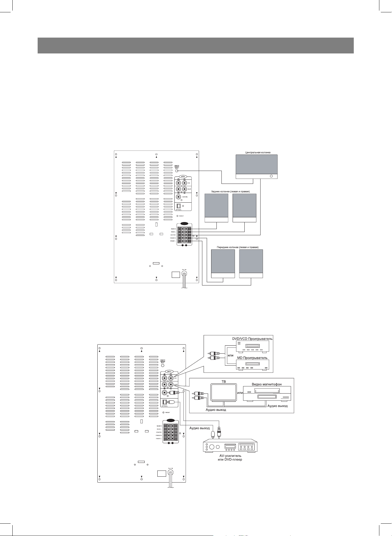
ПОДКЛЮЧЕНИЕ КОЛОНОК
Подключите кабель колонок к соответствующим клеммам на
задней панели усилителя, соблюдая цветовую кодировку и
полярность. Для этого нажмите на соответствующие зажимы.
Не отпуская зажим, вставьте конец соответствующего провода
в клемму (круглое отверстие) и отпустите зажим. Провод будет
зафиксирован. Подключите кабель датчика пульта дистанционного
управления центральной колонки ко входному разъёму датчика,
расположенному на задней панели устройства.
Чтобы получить возможность воспроизводить звук 5.1 каналов, при
помощи кабеля RCA или цифрового кабеля соедините аудио выход
DVD плеера с соответствующим аудио входом системы.
Кабель RCA позволяют подключить аудиовыход DVD плеера или CD
плеера к соответствующему левому (белый) и правому (красный)
CD (AUX 1) входу или входу AUX 2.
ПИТАНИЕ
1. Вставьте сетевую вилку в сетевую розетку.
2. Установите переключатель POWER ON/OFF (Сетевой
выключатель) (11) в положение “ON” (Вкл.). На передней панели
устройства загорится красный индикатор STANDBY (Режим
ожидания) (12).
3. Чтобы включить систему, нажмите кнопку STANDBY (Режим
ожидания) (12) (1) на основном устройстве или на пульте
дистанционного управления. На дисплей передней панели
устройства отобразится уровень громкости.
4. Чтобы полностью выключить систему, установите переключатель
POWER ON/OFF (Сетевой выключатель) (11) в положение OFF
(Выкл.).
Все подключения следует осуществлять при отключенном сетевом питании.
ПОДКЛЮЧЕНИЕ К ИСТОЧНИКУ СИГНАЛА
12
4029.indd 124029.indd 12 07.04.2006 15:53:3007.04.2006 15:53:30
Page 13

РУССКИЙ
ЭКСПЛУАТАЦИЯ
Выберите источник сигнала и звуковой формат.
1. Цифровой источник
Для воспроизведения цифрового сигнала нажмите кнопку INPUT
(Источник) (9) (2) и выберите вход OP (Оптический) или CO
(Коаксиальный).
При воспроизведении MP3 или CD через DVD плеер звук будет
воспроизводиться в двухканальном формате PCM.
2. Источник AUX1 / AUX2
Для воспроизведения звука с CD или DVD плеера (при подключении
с помощью кабеля RCA) нажмите кнопку INPUT (Источник) и
выберите AU (AUX2) или CD (AUX1).
Примечание:
Эта система имеет встроенные декодеры Dolby Digital (AC3)/ Dolby
Prologic.
ЗВУКОВЫЕ ЭФФЕКТЫ:
Чтобы выбрать один из эффектов звучания (Dolby Pro Logic, 3
STEREO или STEREO) нажмите кнопку SURROUND MODE (7) (4).
В режиме Dolby Pro Logic возможен выбор режима звучания
центральной колонки:
Normal:
(активированы все шесть колонок и их индикаторы).
Этот режим следует использовать, когда роль центральной
выполняет компактная колонка, которая не может воспроизводить
басы с частотой ниже 100 Герц. Низкочастотный сигнал
распределится между передней левой и передней правой
колонками.
Wide:
(активированы все шесть колонок и их индикаторы).
Этот режим следует выбрать, если центральная колонка
соответствует левой и правой колонкам и может воспроизводить
частоты ниже 100 Герц.
3. Чтобы проверить правильность подключения всех пяти колонок и
сабвуфера, нажмите кнопку TEST TONE (Тестовый сигнал) (8) (5).
Тестовый сигнал будет воспроизводить в следующем порядке:
передняя левая, центральная, передняя правая, задняя левая,
задняя правая, сабвуфер.
Пока мигает соответствующий индикатор, можно установить
уровень громкости тестового сигнала. Повторное нажатие
на кнопку TEST TONE (Тестовый сигнал) (8) (5) прекращает
воспроизведение тестового сигнала.
4. Чтобы задержку звука в диапазоне 0–15 мс, нажмите кнопку
SURROUND DELAY (Задержка задних каналов) (9) и CENTER
DELAY (Задержка центрального канала) (10).
ВЫКЛЮЧЕНИЕ ЗВУКА (MUTE)
Чтобы отключить звук, нажмите на кнопку MUTE (Выключение звука)
(12), при этом начнет мигать индикатор STANDBY (Режим ожидания)
(12). Для включения звука нажмите кнопку MUTE (Выключение
звука) (12).
ПРЕДУСТАНОВКИ ЭКВАЛАЙЗЕРА
Чтобы подобрать подходящий оттенок звучания, последовательно
нажимайте кнопку PRESET EQUALIZER (Предустановки эквалайзера)
на корпусе системного блока. Предустановки будут применяться
в следующем порядке: Flat (Ровный), Classic (Классический), Pop
(Поп), Rock (Рок).
БЕЗОПАСНОСТЬ ЭКСПЛУАТАЦИИ
Основное устройство, колонки и пульт ДУ нельзя подвергать
воздействию влаги, а также не рекомендуется ставить на них вазы и
прочие ёмкости, содержащие жидкость.
Полное отключение от сети переменного напряжения можно
обеспечить только извлечением сетевой вилки устройства из
сетевой розетки.
Не следует преграждать свободный доступ к сетевой вилке
устройства, которая на время работы с системой должна быть
доступна.
Phantom:
(активировано пять индикаторов колонок, центральная колонка
выключена).
Этот режим следует выбрать, если центральная колонка не
используется.
Звук центрального канала распределяется между передней левой и
передней правой колонками.
Если используется режим 3 Stereo, активируются передняя левая,
центральная, передняя правая, сабвуфер и соответствующие
индикаторы.
Если используется режим Stereo, активируются передняя левая,
передняя правая, сабвуфер и их индикаторы.
Использование функции Dolby Pro Logic допускает применение
режимов NORMAL, WIDE и PHANTOM центральному каналу.
Каждый из этих режимов предусматривает используемый для
центрального канала набор параметров, определяющий объём (или
задержку сигнала).
У каждого из режимов свой эффект задержки сигнала (или эхо).
- NORMAL обеспечивает реальный звук Dolby Pro Logic.
- WIDE позволяет добиться дополнительного акустического
разделения центральной колонки.
- PHANTOM выключает звук центрального канала.
- Передняя левая и правая колонки имитируют звучание
центрального канала.
- Центральная колонка не используется.
Нажатие кнопки EFFECT (Эффект звучания) на пульте
дистанционного управления позволяет выбрать следующие
эффекты звучания: Movie, Classical, Panorama или 2.1.
УРОВЕНЬ ГРОМКОСТИ
1. Чтобы менять уровень громкости, пользуйтесь ручкой
регулировки уровня громкости (2), расположенной на передней
панели устройства или кнопками VOLUME UP/DOWN (2),
расположенными на пульте ДУ. Уровень громкости будет
отображаться на дисплее устройства (0–22).
2. Громкость каждой из шести колонок можно установить, нажав на
кнопку SPEAKER SETUP (Настройки колонок) (3). После того, как
индикатор соответствующей колонки начнёт мигать, установите
нужный уровень громкости с помощью ручки регулировки уровня
громкости (1) кнопки в диапазоне +/-6 дБ.
Влага
Устройство нельзя подвергать действию дождя, влаги и пыли.
Любая жидкость, пролитая на основное устройство, колонку или
пульт ДУ, может послужить причиной поражения пользователя
электрическим током или выхода устройств из строя. Если
вы случайно пролили на устройство жидкость, немедленно
отсоедините сетевой шнур устройства от сетевой розетки, после
чего обратитесь в авторизованный сервисный центр.
Детали корпуса
Не следует снимать закрепленные детали корпуса устройства,
поскольку это может привести к поражению электрическим током.
Режим ожидания
Кнопка STANDBY ON/OFF (Режим ожидания) (10) (1) на пульте
ДУ не отключает усилитель от сети полностью, а потому он
продолжает потреблять электроэнергию. В этой связи из
соображений безопасности и во избежание избыточного расхода
электроэнергии, покидая дом на длительное время, не оставляйте
систему в этом режиме. Отсоедините сетевую вилку устройства от
сетевой розетки.
Открытый огонь
Источники открытого огня, такие как свечи, не следует ставить на
корпуса устройств или рядом с ним.
Сетевой шнур
Позаботьтесь о том, чтобы устройство не стояло на сетевом
шнуре, поскольку шнур может быть повреждён, и стать угрозой для
безопасности окружающих.
Упаковка
По возможности сохраните заводскую упаковку на случай
необходимости транспортировки устройства. Старайтесь
транспортировать систему в ее заводской упаковке.
Электропроводка
Позаботьтесь о том, чтобы все составляющие источника сетевого
питания (включая сетевую вилку, удлинители и иные электрические
соединения отдельных устройств) были выполнены аккуратно и в
соответствии с требованиями изготовителя.
13
4029.indd 134029.indd 13 07.04.2006 15:53:3007.04.2006 15:53:30
Page 14

РУССКИЙ
Вентиляция
Не допускайте блокировки вентиляционных отверстий устройства.
Перегрев может стать причиной повреждения устройства и
отрицательно сказаться на работоспособности системы.
Уход и чистка
Прежде, чем приняться за уход и чистку устройства отключите его
от сетевой розетки. Пользуйтесь слегка увлажнённой салфеткой
и никогда не пользуйтесь аэрозольными или абразивными
чистящими средствами.
Безопасность
Ни в коем случае не позволяйте никому, особенно детям, помещать
какие-либо предметы в разъемы, щели и любые другие отверстия
в корпусе устройства, поскольку это может привести к поражению
электрическим током и повреждению устройства.
Ни в коем случае не продолжайте использовать оборудование, если
у вас возникли даже малейшие сомнения в его исправности, или
если оно повреждено – отключите его, извлеките сетевую вилку
устройства из сетевой розетки и обратитесь в авторизованный
сервисный центр.
ТЕХНИЧЕСКИЕ ХАРАКТЕРИСТИКИ
Рабочее напряжение: 230 В, ~ 50 Гц
Потребляемая мощность: 150 Вт
Максимальная выходная мощность:
Левый и правый каналы: 15 Вт. + 15 Вт
Центральный канал: 15 Вт
Задние каналы: 15 Вт. + 15 Вт
Сабвуфер: 25 Вт
Полоса воспроизводимых частот: 40 - 20000 Гц
Коэффициент нелинейных искажений: 1%
Соотношение сигнал / шум при 1 КГц: 60 дБ
Производитель оставляет за собой право изменять характеристики
прибора без предварительного уведомления.
Срок службы прибора не менее 5-ти лет
Данное изделие соответствует всем требуемым
европейским и российским стандартам безопасности и
гигиены.
Производитель: АНДЕР ПРОДАКТС ГмбХ, Австрия
Нойбаугюртель, 38/7А 1070, Вена, Австрия
14
4029.indd 144029.indd 14 07.04.2006 15:53:3107.04.2006 15:53:31
Page 15

АКУСТИЧНА СИСТЕМА VT-4029
СИСТЕМНИЙ БЛОК (ВИГЛЯД СПЕРЕДУ)
УКРАЇНЬСКИЙ
1. Дисплей
2. Ручка регулювання рівня голосності
3. Кнопка SPEAKER SETUP (Настроювання колонок)
4. Індикатори колонок (FRONT L (Передня Л), CENTER (Центральна),
FRONT R (Передня П), REAR L (Задня Л), SUBWOOFER (Сабвуфер),
REAR R (Задня П))
5. Індикатори режимів об’ємного звучання SURROUND MODE (MOVIE
(Фільм), CLASSIC (Класичний), PANORAMA (Панорамний))
6. Індикатори режиму центрального каналу CENTER MODE (PHANTOM
(Фантом), NORMAL (Нормальний), WІDE (Панорамний))
7. Індикатори режимів об’ємного звучання SURROUND MODE
(PROLOGІC, 3 STEREO, STEREO)
8. Кнопка TEST TONE (Тестовий сигнал)
9. Кнопка ІNPUT (Джерело сигналу)
10. Кнопка STANDBY (Режим чекання)
11. Перемикач POWER ON/OFF (Мережний вимикач)
12. Індикатор STANDBY (Режим чекання)
ПУЛЬТ ДК
1. Кнопка STANDBY (Режим чекання)
2. Кнопка ІNPUT (Джерело сигналу)
3. Кнопки регулювання рівня голосності VOLUME UP/DOWN
4. Кнопки режимів об’ємного звучання SURROUND MODE
(PROLOGІC, 3 STEREO, STEREO)
5. Кнопка TEST TONE (Тестовий сигнал)
6. Кнопки PRESET EQUALІZER (Эквалайзер) (FLAT (Рівний), CLASSІC
(Класичний), ROCK (Рок), POP (Поп), JAZZ (Джаз))
7. Кнопки режиму центрального каналу CENTER MODE (PHANTOM
(Фантом), NORMAL (Нормальний), WІDE (Панорамний))
8. Кнопки SPEAKER SETUP (Настроювання колонок) (FRONT L
(Передня Л), CENTER (Центральна), FRONT R (Передня П), REAR
L (Задня Л), SUBWOOFER (Сабвуфер), REAR R (Задня П))
9. Кнопки SURROUND DELAY (Затримка задніх каналів)
10. Кнопка CENTER DELAY (Затримка центрального каналу)
11. Кнопка EFFECT (Ефект) (MOVІE (Фільм), CLASSІCAL (Класичний),
PANORAMA (Панорама))
12. Кнопка MUTE (Вимикання звуку)
ВЕНТИЛЯЦІЯ
Щоб уникнути перегріву, пристрій повинен добре вентилюватися.
Не накривайте корпус пристрою і не встановлюйте його в місця з обмеженою вентиляцією. Переконайтеся в тому, що по обидва боки
корпуса і над ним є вільний простір не менш 20 см.
ВКЛЮЧЕННЯ СИСТЕМИ
Установіть перемикач POWER ON/OFF (11) у положення “ON”, пристрій перейде в режим чекання. Для включення системи натисніть
кнопку STANDBY (10) (Режим чекання).
РОЗТАШУВАННЯ КОЛОНОК
Ця акустична система має шість звукових каналів. Динамік сабвуфера знаходиться в самому пристрої.
Установіть колонки як це зображено на приведеній нижче схемі.
а. Передні колонки
б. Основний пристрій з сабвуфером
в. Центральна колонка
м. Задні колонки
д. Місце для глядача/слухача
Пульт працює від двох батарейок типу “AA” або “R6”.
Розташуйте центральну колонку між передніми колонками. Можлива
установка центральної колонки на корпус телевізора, тому що вона
має захисний магнітний екран. У задніх колонок немає екранировки
магнітного поля. Не розташовуйте їх поруч з телевізором або комп’ютерним дисплеєм, оскільки це може привести до порушення переда-
15
4029.indd 154029.indd 15 07.04.2006 15:53:3107.04.2006 15:53:31
Page 16
УКРАЇНЬСКИЙ
чі кольору зображення. Не ставте на колонки магнітофонні касети.
Якщо розташувати основний пристрій у безпосередній близькості від
телевізора, це може викликати появу перекручувань зображення.
Усі підключення здійснюйте при відключеному мережному живленні.
ПІДКЛЮЧЕННЯ КОЛОНОК
Підключіть кабель колонок до відповідних клем на задній панелі підсилювача, дотримуючи колірного кодування і полярності. Для цього
натисніть на відповідні затиски. Не відпускаючи затиск, вставте кінець відповідного проводу в клему (круглий отвір) і відпустіть затиск.
Провід буде зафіксований. Підключіть кабель датчика пульта дистанційного керування центральної колонки до вхідного рознімання датчика, розташованого на задній панелі пристрою.
Усі підключення здійснюйте при відключеному мережному живленні.
Кабель RCA дозволяє підключити аудіо вихід DVD програвача або CD
програвача до відповідного лівого (білий) і правого (червоний) CD
(AUX 1) входу або входу AUX 2.
ЖИВЛЕННЯ
1. Вставте мережну вилку в мережну розетку.
2. Установіть перемикач POWER ON/OFF (Мережний вимикач) (11) у
положення “ON” (Вкл.). На передній панелі пристрою загориться
червоний індикатор STANDBY (Режим чекання) (12).
3. Щоб включити систему, натисніть кнопку STANDBY (Режим чекання) (12) (1) на основному пристрої або на пульті дистанційного
керування. На дисплеї передньої панелі пристрою відобразиться
рівень голосності.
4. Щоб цілком виключити систему, установіть перемикач POWER
ON/OFF (Мережний вимикач) (11) у положення OFF (Викл.).
ПІДКЛЮЧЕННЯ ДО ДЖЕРЕЛА СИГНАЛУ
Щоб одержати можливість відтворювати звук 5.1 каналів, за допомогою кабелю RCA або цифрового кабелю з’єднайте аудіо вихід DVD
програвача з відповідним аудіо входом системи.
16
4029.indd 164029.indd 16 07.04.2006 15:53:3107.04.2006 15:53:31
Page 17

УКРАЇНЬСКИЙ
ЕКСПЛУАТАЦІЯ
Виберіть джерело сигналу і звуковий формат.
1. Цифрове джерело
Для відтворення цифрового сигналу натисніть кнопку ІNPUT (Джерело)
(9) (2) і виберіть вхід OP (Оптичний) або CO (Коаксіальний).
При відтворенні MP3 або CD через DVD програвач звук буде відтворюватися в двоканальному форматі PCM.
2. Джерело AUX1/AUX2
Для відтворення звуку з CD або DVD програвача (при підключенні за
допомогою кабелю RCA) натисніть кнопку ІNPUT (Джерело) і виберіть
AU (AUX2) або CD (AUX1).
Примітка:
Ця система має убудовані декодери Dolby Dіgіtal (AC3)/Dolby
Prologic.
ЗВУКОВІ ЕФЕКТИ
Щоб вибрати один з ефектів звучання (Dolby Pro Logіc, 3 STEREO або
STEREO), натисніть кнопку SURROUND MODE (7) (4).
У режимі Dolby Pro Logіc можливий вибір режиму звучання центральної колонки:
Normal:
(активовані всі шість колонок і їх індикатори).
Використовуйте цей режим, коли роль центральної виконує компактна колонка, що не може відтворювати баси з частотою нижче 100 Гц.
Низькочастотний сигнал розподілиться між передніми лівими і передньою правою колонками.
Wide:
(активовані всі шість колонок і їх індикатори).
Використовуйте цей режим, якщо центральна колонка відповідає лівій і правій колонкам і може відтворювати частоти нижче 100 Гц.
Phantom:
(активовано п’ять індикаторів колонок, центральна колонка виключена).
Вибирайте цей режим, якщо центральна колонка не використовується.
Звук центрального каналу розподіляється між передньою лівою і передньою правою колонками.
Якщо використовується режим 3 Stereo, активуються передня ліва,
центральна, передня права, сабвуфер і відповідні індикатори.
Якщо використовується режим Stereo, активуються передня ліва, передня права, сабвуфер і їх індикатори.
Використання функції Dolby Pro Logіc допускає застосування режимів NORMAL, WІDE і PHANTOM центральному каналу.
Кожен з цих режимів передбачає використовуваний для центрального каналу набір параметрів, що визначає об’єм (або затримку сигналу).
У кожного з режимів свій ефект затримки сигналу (або луна).
- NORMAL забезпечує реальний звук Dolby Pro Logіc.
- WІDE дозволяє домогтися додаткового акустичного поділу центральної колонки.
- PHANTOM виключає звук центрального каналу.
- Передня ліва і права колонки імітують звучання центрального каналу.
- Центральна колонка не використовується.
Натискання кнопки EFFECT (Ефект звучання) на пульті дистанційного керування дозволяє вибрати наступні ефекти звучання: Movіe,
Classіcal, Panorama або 2.1.
РІВЕНЬ ГОЛОСНОСТІ
1. Щоб змінювати рівень голосності, користуйтеся ручкою регулю-
вання рівня голосності (2), розташованою на передній панелі пристрою або кнопками VOLUME UP/DOWN (2), розташованими на
пульті ДК. Рівень голосності буде відображатися на дисплеї пристрою (0-22).
2. Голосність кожної із шести колонок можна встановити, натиснув-
ши на кнопку SPEAKER SETUP (Настроювання колонок) (3). Після
того, як індикатор відповідної колонки почне мигати, установіть
потрібний рівень голосності за допомогою ручки регулювання рівня голосності (1) кнопки в діапазоні +/-6 дБ.
3. Щоб перевірити правильність підключення всіх п’яти колонок і
сабвуфера, натисніть кнопку TEST TONE (Тестовий сигнал) (8) (5).
Тестовий сигнал буде відтворювати в наступному порядку: пе-
редня ліва, центральна, передня права, задня ліва, задня права,
сабвуфер.
Поки мигає відповідний індикатор, можна установити рівень го-
лосності тестового сигналу. Повторне натискання на кнопку TEST
TONE (Тестовий сигнал) (8) (5) припиняє відтворення тестового
сигналу.
4. Щоб установити затримку звуку в діапазоні 0-15 мс., натисніть
кнопку SURROUND DELAY (Затримка задніх каналів) (9) і CENTER
DELAY (Затримка центрального каналу) (10).
ВІДКЛЮЧЕННЯ ЗВУКУ (MUTE)
Щоб відключити звук, натисніть на кнопку MUTE (Відключення звуку)
(12), при цьому почне мигати індикатор STANDBY (Режим чекання)
(12). Для включення звуку натисніть кнопку MUTE (Відключення звуку) (12).
ПОПЕРЕДНІ УСТАНОВКИ ЕКВАЛАЙЗЕРА
Щоб підібрати бажаний відтінок звучання, послідовно натискайте
кнопку PRESET EQUALІZER (Попередні установки еквалайзера) на
корпусі системного блоку. Попередні установки будуть застосовуватися в наступному порядку: Flat (Рівний), Classіc (Класичний), Pop
(Поп), Rock (Рок).
БЕЗПЕКА ЕКСПЛУАТАЦІЇ
Основний пристрій, колонки і пульт ДК не можна піддавати впливу
вологи, а також не рекомендується ставити на них вази та інші ємності, що містять рідину.
Повне відключення від мережі перемінної напруги можна забезпечити тільки витягом мережної вилки пристрою з мережної розетки.
Не слід перепиняти вільний доступ до мережної вилки пристрою, що
на час роботи з системою повинна бути доступна.
Волога
Пристрій не можна піддавати впливу дощу, вологи і пилу. Будь-яка
рідина, пролита на основний пристрій, колонку або пульт ДК, може
бути причиною поразки користувача електричним током або виходу
пристроїв з ладу. Якщо ви випадково пролили на пристрій рідину, негайно від’єднайте мережний шнур пристрою від мережної розетки,
після чого зверніться в авторизований сервісний центр.
Деталі корпуса
Не слід знімати закріплені деталі корпуса пристрою, оскільки це може
призвести до поразки електричним током.
Режим чекання
Кнопка STANDBY ON/OFF (Режим чекання) (10) (1) на пульті ДК не
відключає підсилювач від мережі цілком, а тому він продовжує споживати електроенергію. У цьому зв’язку з розумінь безпеки і щоб
уникнути надлишкової витрати електроенергії, залишаючи будинок
на тривалий час, не залишайте систему в цьому режимі. Від’єднайте
мережну вилку пристрою від мережної розетки.
Відкритий вогонь
Джерела відкритого вогню, такі як свічі, не слід ставити на корпуси
пристроїв або поруч з ним.
Мережний шнур
Подбайте про те, щоб пристрій не стояв на мережному шнурі, оскільки шнур може бути ушкоджений і стати погрозою для безпеки.
Упакування
По можливості збережіть заводське упакування на випадок необхідності транспортування пристрою. Намагайтеся транспортувати систему в її заводському упакуванні.
Електропроводка
Подбайте про те, щоб усі складові джерела мережного живлення
(включаючи мережну вилку, подовжувачі та інші електричні з’єднання окремих пристроїв) були виконані акуратно і відповідно до вимог
виготовлювача.
Вентиляція
Не допускайте блокування вентиляційних отворів пристрою. Перегрів
може стати причиною ушкодження пристрою і негативно позначитися на працездатності системи.
Догляд і чищення
Перш ніж прийнятися за чищення пристрою, відключіть його від ме-
17
4029.indd 174029.indd 17 07.04.2006 15:53:3107.04.2006 15:53:31
Page 18

УКРАЇНЬСКИЙ
режної розетки. Користуйтеся злегка зволоженою серветкою і ніколи
не користуйтеся аерозольними або абразивними засобами, що чистять.
Безпека
Ні в якому разі не дозволяйте нікому, особливо дітям, поміщати якінебудь предмети в рознімання, щілини і будь-які інші отвори в корпусі пристрою, оскільки це може призвести до поразки електричним
током і ушкодженню пристрою.
Ні в якому разі не продовжуйте використовувати устаткування, якщо
у вас виникли навіть найменші сумніви в його справності, або якщо
воно ушкоджено - відключіть його, витягніть мережну вилку пристрою
з мережної розетки і зверніться в авторизований сервісний центр.
ТЕХНІЧНІ ХАРАКТЕРИСТИКИ
Робоча напруга: 230 В, ~ 50 Гц
Споживана потужність: 150 Вт
Максимальна вихідна потужність:
Лівий і правий канали: 15 Вт + 15 Вт
Центральний канал: 15 Вт
Задні канали: 15 Вт + 15 Вт
Сабвуфер: 25 Вт
Смуга відтворених частот: 40 - 20000 Гц
Коефіцієнт нелінійних перекручувань: 1%
Співвідношення сигнал / шум при 1 КГц: 60 дБ
Виробник залишає за собою право змінювати характеристики приладу без попереднього повідомлення.
Строк служби приладу не менше 5-ти років.
Гарантія
Докладні умови гарантії можна отримати в дилера, що продав дану
апаратуру. При пред’явленні будь-якої претензії протягом терміну дії
даної гарантії варто пред’явити чек або квитанцію про покупку.
Даний виріб відповідає вимогам до електромагнітної сумісності, що пред’являються директивою 89/336/ЄЕС Ради
Європи й розпорядженням 23/73 ЄЕС по низьковольтних
апаратурах.
18
4029.indd 184029.indd 18 07.04.2006 15:53:3107.04.2006 15:53:31
Page 19

АКУСТИКАЛЫҚ СИСТЕМАСЫ VT-4029
ЖҮЙЕЛІ БЛОК (АЛДЫНАН РЕҢІ)
ҚАЗАҚ
1. Дисплей
2. Дауыс дəреженің реттеу тұтқа
3. SPEAKER SETUP түймесі (Колонкалардың икемдеуі)
4. Колонкалардың индикаторлары (FRONT L (Алдынғы Л), CENTER
(Орталық), FRONT R (Алдынғы П), REAR L (Артқы Л), SUBWOOFER
(Сабвуфер), REAR R (Артқы П))
5. Мөлшер дыбыс шығару тəртіптердің индикаторлары SURROUND
MODE (MOVIE (Фильм), CLASSIC (Классикалық), PANORAMA
(Панорамалық))
6. Орталық канал тəртіптің индикаторлары CENTER MODE (PHANTOM
(Фантом), NORMAL (Нормалы), WIDE (Панорамалық))
7. Мөлшер дыбыс шығару тəртіптердің индикаторлары SURROUND
MODE (PROLOGIC, 3 STEREO, STEREO)
8. TEST TONE түймесі (Сынамақты белгі)
9. INPUT түймесі (Белгінің негізі)
10. STANDBY түймесі (Аялдау тəртібі)
11. POWER ON/OFF айырып-қосқыш (Сетьтегі айырғыш)
12 STANDBY Индикаторы (Аялдау тəртібі)
АРАҚАТЫСТЫҚ БАСҚАРУ ПУЛЬТІ
1. STANDBY түймесі (Аялдау тəртібі)
2. INPUT түймесі (Белгінің негізі)
3. VOLUME UP/DOWN Дауыс дəреженің реттеу түймелер
4. SURROUND MODE (PROLOGIC, 3 STEREO, STEREO) Мөлшер
дыбыс шығару тəртіптердің түймелері
5. TEST TONE түймесі (Сынамақты белгі)
6. PRESET EQUALIZER түймелер (Эквалайзер) (FLAT (Тегіс),
CLASSIC (Классикалық), ROCK (Рок), POP (Поп), JAZZ (Джаз))
7. Орталық канал тəртіптің түймелері CENTER MODE (PHANTOM
(Фантом), NORMAL (Нормалы), WIDE (Панорамалық))
8. SPEAKER SETUP түймелер (Колонкалардың икемдеуі) (FRONT L
(Алдынғы Л), CENTER (Орталық), FRONT R (Алдынғы П), REAR L
(Артқы Л), SUBWOOFER (Сабвуфер), REAR R (Артқы П))
9. SURROUND DELAY түймелер (Артқы каналдардың тоқтата тұруы)
10. CENTER DELAY түймесі (Орталық каналдың тоқтата тұруы)
11. EFFECT түймесі (Эффект) (MOVIE (Фильм), CLASSICAL
(Классикалық), PANORAMA (Панорама))
12. MUTE түймесі (Дыбысты сөндіру)
“AA” немесе “R6” түріндегі екі батареядан пульт жұмыс істейді..
19
ВЕНТИЛЯЦИЯ
Жабдық қызып кетпеу ұшін ол жақсы желдету керек.
Жабдықтың корпусын ішнəрсемен жаймаңыз жəне оны шағын
вентиляция бар жерлерде орнатпаңыз. Тексеріңіз, корпустың екі
жағынан жəне оның үстінде бос кеңістік 20 см кем еместей бар екенін.
СИСТЕМАНЫ ҚОСУ
POWER ON/OFF (11) айырып-қосқышты “ON” жайға орнатыңыз,
жабдық аялдау тəртібіне өтеді. Системаны қосу ұшін STANDBY (10)
(Аялдау тəртібі) түймені басыңыз.
КОЛОНКАЛАРДЫҢ ЖАЙҒАСТЫРУЫ
Осы акустикалық системада алты дыбыс каналдар бар. Сабвуфердің
динамикасы жабдықтың ішінде орнатылған.
Колонкаларды төмендегі көрсетілген схема бойынша орнатыңыз.
а. Алдынғы колонкалар
б. Негізгі жабдық сабвуфермен
в. Орталық колонка
г. Артқы колонкалар
д. Көрерменге/ тыңдаушыға арналған орын
Орталық колонканы алдынғы колонкалардың арасында жайғастырыңыз.
Теледидар корпустың үстіне орталық колонканы орнатуға мүмкіндік
бар, себебі ода қорғану магнит экраны бар.
Артқы колонкаларда магнит өрістің экранировкасы жоқ.
4029.indd 194029.indd 19 07.04.2006 15:53:3207.04.2006 15:53:32
Page 20

ҚАЗАҚ
Оларды теледидармен немесе компьютер дисплеймен жақын
жайғастырмаңыз, сондықтан ол бейнелеудің түс алып беруін
бұзылуына келтіреді.
Колонкалардың үстіне магнитофондық кассеталарды орнатпаңыз.
Егер негізгі жабдықты теледидарға жақын жайғастырса, онда ол
бейнелеудің бұрмалауын келтіреді.
Бəрі қосуларды өшірілген электр токта жасау керек.
КОЛОНКАЛАРДЫ ҚОСУ
Колонкалардың кабель күшейткіштің артқы панельдегі сəйкес
клеммаларға қосыңыз, түсті кодировканы жəне өрістерін сақтаңыз.
Соол ұшін сəйкес қысымдарға басыңыз. Қысымды жибермей, сəйкес
сымның соңын клеммаға кіргізіңіз (домалақ тесік) жəне қысымды
жиберіңіз. Сым бекітіледі. Орталық колонканың арақатыстық басқару
пульт датчик кабелін датчиктін кіру айырғышына қосыңыз, ол жабдықтың
артқы панельде орнатылған.
Бəрі қосуларды өшірілген электр токта жасау керек.
5.1 каналдардың дыбысты қайташығармау мүмкіндік алу ұшін, RCA
кабель немесе сандық кабель арқылы, DVD плеердің аудио шығуын
системаның сəйкес аудио кіруіне кіргізіңіз.
RCA кабелі DVD плеердің немесе CD плеердің аудиошығуын сəйкес
сол (ақ) жəне оң (қызыл) CD (AUX 1) кіруімен немесе AUX 2 кіруімен
қосуын береді.
ҚУАТ АЛУЫ
1. Электр айырғыны электр розеткаға тығыңыз.
2. POWER ON/OFF (Электр айырғыш) (11) айырып-қосқышты “ON”
(Вкл.) жайға орнатыңыз. Жабдықтың алдынғы панельде қызыл
индикатор STANDBY (Аялдау тəртібі) (12) жанады.
3. Системаны қосу ұшін, негізгі жабдықта немесе арақатыстық басқару
пультегі STANDBY (Аялдау тəртібі) (12) түймені басыңыз.Жабдықтың
алдынғы панельде дауыстың дəрежесі көрсетіледі.
4. Системаны толық қосу ұшін, POWER ON/OFF (Электр айырғыш)
(11) айырып-қосқышты OFF (Выкл.) жайға орнатыңыз.
БЕЛГІНІҢ НЕГІЗІНЕ ҚОСУЫ
20
4029.indd 204029.indd 20 07.04.2006 15:53:3207.04.2006 15:53:32
Page 21

ҚАЗАҚ
ПАЙДАЛАНУ
Белгінің негізін жəне дыбыстың форматын таңдаңыз.
1. Сандық негізі
Сандық белгіні қайта шығару ұшін INPUT (Негізі) (9) (2) түймені басыңыз
жəне OP (Оптикалық) немесе CO (Коаксиальді) кіруді таңдаңыз.
DVD плеер арқылы MP3 немесе CD қайта шығармада дыбыс PCM екіканальді форматта қайта шығарылады.
2. AUX1 / AUX2 Негізі
CD немесе DVD плеерден дыбысты қайта шығару ұшін (RCA кабель
арқылы қосылғанда) INPUT (Негізі) түймені басыңыз жəне AU (AUX2)
немесе CD (AUX1) таңдаңыз.
Ескерту:
Осы системада ішіне құрылған Dolby Digital (AC3)/ Dolby Prologic.
ДЫБЫС НƏТИЖЕЛЕРІ:
Дыбыс шығару нəтижелердің біреуін таңдау ұшін (Dolby Pro Logic,
3 STEREO немесе STEREO) SURROUND MODE (7) (4) түймені
басыңыз.
Dolby Pro Logic тəртіпте орталық колонканың дыбыс шығару тəртібін
таңдау мүмкіндігі бар:
Normal:
(бəрі алты колонкалар жəне олардың индикаторлары активті).
Осы тəртіпті қолдануға болады, егер орталықтың қызметін компакті колонка жасағанды, ол бастарды 100 Герц төмен жиілікпен қайта
шығарамайды. Төменжиілікті белгі таратылады алдынғы сол жəне
алдынғы оң колонкалар арасында.
Wide:
(бəрі алты колонкалар жəне олардың индикаторлары активті).
Осы тəртіпті таңдау керек, егер орталық колонкасы сол жəне оң
колонкаларға сəйкес болса жəне ол 100 Герц төмен жиілікпен қайта
шығарады.
Phantom:
(колонкалардың бес ииндикаторлары активті, орталық колонка
сөндірілген).
Осы тəртіпті таңдау керек, егер орталық колонкасы пайдаланбаса.
Орталық каналдың дыбыс алдынғы сол жəне алдынғы оң
колонкалардың арасында таратылады.
Егер 3 Stereo тəртіп пайдаланса, алдынғы сол, орталық, алдынғы оң,
сабвуфер жəне сəйкес индикаторлар активті болады.
Егер Stereo тəртіп пайдаланса, алдынғы сол, алдынғы оң, сабвуфер
жəне сəйкес индикаторлар активті болады.
Dolby Pro Logic функцияларды қолдануы орталық каналға NORMAL,
WIDE жəне PHANTOM тəртіптерді пайдалануға жибереді.
Əрбір осы тəртіптерден орталық каналға ұшін пайдалану
параметрлардың терімін қамытады, мөлшерді (немесе белгінің аялдауын) айқындаушы.
Эр тəртіптердің өз белгі аялдау нəтижесі (немесе думпу) бар
- NORMAL Dolby Pro Logic нақты дыбысты жеткізеді.
- WIDE орталық колонканың қосымша акустикалық бөлуін білек береді.
- PHANTOM орталық колонканың дыбыс сөндіреді.
- Алдынғы сол жəне оң колонкалар орталық колонканың дыбыс
шығаруын илектейді.
- Орталық колонка қолданбайды.
Сынамақты белгі келесі ретте қайта шығарылады:алдынғы сол,
орталық, алдынғы оң, артқы сол, артқы оң, сабвуфер.
Сəйкес индикатор жыпылықтап тұрғанда, сынамақты белгі дауыс
дəрежесін орнатуға болады. Қайта TEST TONE (Сынамақты белгі)
(8) (5) түйме басуы сынамақты белгінің қайта шығаруын тоқтатады.
4. 0–15 мс диапазонда дыбысты аялдау ұшін, SURROUND DELAY
(артқы каналдарды аялдауы) (9) жəне CENTER DELAY (Орталық
каналды аялдауы) (10) түймені басыңыз.
ДЫБЫСТЫ СӨНДІРУ (MUTE)
Дыбысты сөндіру ұшін MUTE (Дыбыс сөндіру) (12) түймені басыңыз,
сонда STANDBY (Аялдау тəртібі) (12) индикаторы жыпылықтайды.
Дыбысты қосу ұшін MUTE (Дыбыс сөндіру) (12) түймені басыңыз.
ЭКВАЛАЙЗЕРДІҢ АЛДЫНА ОРНАТУЛАРЫ
Жарайтын дыбыс шығару реңің жидыру ұшін, дəйекті түрде PRESET
EQUALIZER (Эквалайзердің алдына орнатулары) түймені басыңыз системдік блоктың корпусында орнатылған. Алдына орнатулары келесі
ретте пайдаланады: Flat (Тегіс), Classic (Классикалық), Pop (Поп), Rock
(Рок).
ПАЙДАЛАНУДЫҢ ҚАУЫПСІЗДІГІ
Негізгі жабдықты, колонкаларды жəне АБ пультті дымқыл əсеріне
жеткізуге болмайды, тағы да олардың үстіне вазаны жəне басқа
сиымдылықтарды, ішінде сұйықтықтар болса, қоюға ұсынылмайды.
Жабдықтың электр сымын электр розеткадан суырып алынғанда, сонда тек қана толық сөндіруін қамтамасыз етуге болады.
Жабдықтың электр айырғына бос мүмкіндігін бөгет жасауға болмайды,
системамен жұмыс істеп тұрғанда ол жетімді болу керек.
Дымқыл
Жабдыққа жамбыр, дымқыл жəне шаң тигізуге болмайды. Əртүрлі
сұйықтық, негізгі жабдыққа, колонкаға немесе АБ пультке құюылған,
пайдаланушыны электр токпен ұруының себебі болу мүмкін немесе жабдықтардың бұзылуы мүмкін. Егер Сіз əлдеқалай жабдыққа
сұйықтықты құйсаңыз, дереу жабдықтың электр айырғыны электр
розеткадан суырып алыңыз, содан кейін авторизациялық өкіліңізге
хабарлаңыз.
Корпустың бөлшектері
Жабдық корпустың бекіткен бөлшектерді шешуге болмайды, сондықтан
ол электр токапен қруына келтіреді.
Аялдау тəртібі
АБ пультегі (1) STANDBY ON/OFF (Аялдау тəртібі) (10) түймесі
күшейткішті электр токтан толық сөндірмейді, сондықтан ол электрэнергияны пайдаланы береді. Осы жағдайда қауыпсыздық пікірден жəне артық электроэнергияны жұмсамау ұшін, ұй жайыңызды
ұзақ уақытқа тастап кетіп баражатырсаңыз, системаны осы тəртіпте
қалдырмаңыз. Жабдықтың электр айырғынын электр розеткадан суырып алыңыз.
Ашық от
Ашық оттын деректері, бағаналар, жабдықтардың корпусына немесе
олардың қасына қоюға болмайды.
Электр шнур
Қамданыңыз, жабдық электр шнурдың үстінде тұрмасын, себебі шнур
зақым болу мүмкін, жəне ол айналардың қауіпсыздығына əсер беру
мүмкін.
Арақатыстық басқару пульттегі EFFECT (дыбыс шығару нəтижесі)
түймелер басуы келесі дыбыс шығару нəтижелерді: Movie, Classical,
Panorama немесе 2.1. таңдауды береді.
ДАУЫСТЫҢ ДƏРЕЖЕСІ
1. Даустың дəрежесін ауыстыру ұшін, дауыс дəреже реттеу тұтқамен(2)
пайдаланыңыз, ол жабдықтың алдынғы панельде орнатылған
немесе VOLUME UP/DOWN (2) түймелермен пайдаланыңыз, олар
АБ пультте орнатылған. Жаюдықтың дисплейінде (0–22) дайыстың
дəрежесі көрсетіледі.
2. Əр дауысты алты колонкалардың икемдеуге болады, SPEAKER
SETUP (Колонкалардың икемдеуі) (3) түймені басып. Сəйкес
колонканың индикаторы жыпылықтату бастағаннан кейін, дауыстың
керек дəрежесін орнатыңыз дауыс дəреже реттеу тұтқа арқылы (1)
түйменің +/-6 дБ диапазонда.
3. Бəрі бес колонкалардың жəне сабвуфердің қосу дүрыстығын тексеру ұшін, TEST TONE (Сынамақты белгі) (8) (5)түймені басыңыз.
Орама
Мүмкіндігіне қарай зауыттық орамасын сақтыңыз егерде жабдықты
тасу керек жағдай болса. Системаны өзінің зауыт орамасында тасуға
тырысыңыз.
Электр жүргізу
Қамданыңыз, электр ток негізінің бəрі жасаушылары (соның ішінде
электр айырғы, ұзартқыш жəне бөлек жабдықтардың басқа электр
қосылыстары) ұқыпты орындалған болсын жəне өндірушінің талапана
сəйкес.
Вентиляция
Жабдықтың желдеткіш тесіктері шектеуін келтірмеңіз. Қызып кету
жабдықтың бұзулуының себебі болу мүмкін жəне ол системаның
жұмысшылығына жаман əсер береді.
21
4029.indd 214029.indd 21 07.04.2006 15:53:3207.04.2006 15:53:32
Page 22

ҚАЗАҚ
Күту жəне тазалау
Жабдықтың күтімін жəне тазалауын бастау ұшін алдында электр розеткадан суырып алыңыз. Жай ғана суланған матамен қолданыңыз
жəне еш қашан аэрозольді немесе абразивтік тазалайтын құралдармен
қолданбаңыз.
Қауіпсіздік
Еш уақытта ішкімге, əсіресе балаларға, жабдықтың корпусындағы
айырғыштардың, тесіктердің жəне басқа тесіктердің ішіне əртүрлы заттарды салуға, рұқсат етпеңіз, сондықтан ол электр токпен ұруына жəне
жабдықтың бұзылуына келтіреді. Еш уақытта жабдықпен қолданбаңыз,
егерде Сізде оның жөнділігінде кішкентай күмəн болса, немесе егер ол
бұзылған болса – оны сөндіріңіз, жабдықтың электр сымын розеткадан
суырып алыңыз жəне авторизациялық өкіліңізге хабарлаңыз.
ТЕХНИКАЛЫҚ СИПАТАМАЛАР
Жұмыс кернеуі: 230 В, ~ 50 Гц
Пайдалану қуаттылығы: 150 Вт
Ен барынша шығу қуаттылығы:
Сол жəне оң каналдар: 15 Вт. + 15 Вт
Орталық канал: 15 Вт
Артқы каналдар: 15 Вт. + 15 Вт
Сабвуфер: 25 Вт
Қайташығармалы жиіліктердің алқапы: 40 - 20000 Гц
Сызықтық емес бұрмалаудың коэффициенті: 1%
Белгі / шуыл 1 КГц-те ара қатынасы: 60 дБ
Өндіруші өз артынан құқықты қалдырады аспаптың сипаттмаларды өзгертуге алдына ескертпесіз.
Аспаптың жұмыс мерзімі 5 жылдан кем емес.
Гарантиялық мiндеттiлiгi
Гарантиялық жағдайдағы қаралып жатқан бөлшектер дилерден тек
сатып алынған адамға ғана берiледi. Осы гарантиялық мiндеттiлiгiндегi шағымдалған жағдайда төлеген чек немесе квитанциясын көрсетуi
қажет.
Бұл тауар ЕМС – жағдайларға сəйкес келедi негiзгi Мiндеттемелер 89/336/EEC Дерективаның ережелерiне енгiзiлген
Төменгi Ережелердiң Реттелуi (73/23 EEC)
22
4029.indd 224029.indd 22 07.04.2006 15:53:3207.04.2006 15:53:32
Page 23

4029.indd 234029.indd 23 07.04.2006 15:53:3207.04.2006 15:53:32
Page 24

4029.indd 244029.indd 24 07.04.2006 15:53:3207.04.2006 15:53:32
 Loading...